EP1147328B1 - Compact actuator - Google Patents
Compact actuator Download PDFInfo
- Publication number
- EP1147328B1 EP1147328B1 EP00903041A EP00903041A EP1147328B1 EP 1147328 B1 EP1147328 B1 EP 1147328B1 EP 00903041 A EP00903041 A EP 00903041A EP 00903041 A EP00903041 A EP 00903041A EP 1147328 B1 EP1147328 B1 EP 1147328B1
- Authority
- EP
- European Patent Office
- Prior art keywords
- screw
- actuator according
- support bearing
- housing
- outer ring
- Prior art date
- Legal status (The legal status is an assumption and is not a legal conclusion. Google has not performed a legal analysis and makes no representation as to the accuracy of the status listed.)
- Expired - Lifetime
Links
- 230000007246 mechanism Effects 0.000 claims abstract description 33
- 210000000078 claw Anatomy 0.000 claims description 7
- 230000008878 coupling Effects 0.000 claims description 4
- 238000010168 coupling process Methods 0.000 claims description 4
- 238000005859 coupling reaction Methods 0.000 claims description 4
- 239000011248 coating agent Substances 0.000 claims 2
- 238000000576 coating method Methods 0.000 claims 2
- OKTJSMMVPCPJKN-UHFFFAOYSA-N Carbon Chemical compound [C] OKTJSMMVPCPJKN-UHFFFAOYSA-N 0.000 claims 1
- 229910052799 carbon Inorganic materials 0.000 claims 1
- 239000004519 grease Substances 0.000 claims 1
- 238000005096 rolling process Methods 0.000 claims 1
- 238000005452 bending Methods 0.000 description 13
- 230000005489 elastic deformation Effects 0.000 description 1
- 238000011068 loading method Methods 0.000 description 1
- 238000004804 winding Methods 0.000 description 1
Images


Classifications
-
- F—MECHANICAL ENGINEERING; LIGHTING; HEATING; WEAPONS; BLASTING
- F16—ENGINEERING ELEMENTS AND UNITS; GENERAL MEASURES FOR PRODUCING AND MAINTAINING EFFECTIVE FUNCTIONING OF MACHINES OR INSTALLATIONS; THERMAL INSULATION IN GENERAL
- F16H—GEARING
- F16H25/00—Gearings comprising primarily only cams, cam-followers and screw-and-nut mechanisms
- F16H25/18—Gearings comprising primarily only cams, cam-followers and screw-and-nut mechanisms for conveying or interconverting oscillating or reciprocating motions
- F16H25/20—Screw mechanisms
- F16H25/22—Screw mechanisms with balls, rollers, or similar members between the co-operating parts; Elements essential to the use of such members
-
- F—MECHANICAL ENGINEERING; LIGHTING; HEATING; WEAPONS; BLASTING
- F16—ENGINEERING ELEMENTS AND UNITS; GENERAL MEASURES FOR PRODUCING AND MAINTAINING EFFECTIVE FUNCTIONING OF MACHINES OR INSTALLATIONS; THERMAL INSULATION IN GENERAL
- F16D—COUPLINGS FOR TRANSMITTING ROTATION; CLUTCHES; BRAKES
- F16D65/00—Parts or details
- F16D65/14—Actuating mechanisms for brakes; Means for initiating operation at a predetermined position
- F16D65/16—Actuating mechanisms for brakes; Means for initiating operation at a predetermined position arranged in or on the brake
- F16D65/18—Actuating mechanisms for brakes; Means for initiating operation at a predetermined position arranged in or on the brake adapted for drawing members together, e.g. for disc brakes
-
- H—ELECTRICITY
- H02—GENERATION; CONVERSION OR DISTRIBUTION OF ELECTRIC POWER
- H02K—DYNAMO-ELECTRIC MACHINES
- H02K7/00—Arrangements for handling mechanical energy structurally associated with dynamo-electric machines, e.g. structural association with mechanical driving motors or auxiliary dynamo-electric machines
- H02K7/06—Means for converting reciprocating motion into rotary motion or vice versa
-
- F—MECHANICAL ENGINEERING; LIGHTING; HEATING; WEAPONS; BLASTING
- F16—ENGINEERING ELEMENTS AND UNITS; GENERAL MEASURES FOR PRODUCING AND MAINTAINING EFFECTIVE FUNCTIONING OF MACHINES OR INSTALLATIONS; THERMAL INSULATION IN GENERAL
- F16D—COUPLINGS FOR TRANSMITTING ROTATION; CLUTCHES; BRAKES
- F16D66/00—Arrangements for monitoring working conditions, e.g. wear, temperature
- F16D2066/003—Position, angle or speed
-
- F—MECHANICAL ENGINEERING; LIGHTING; HEATING; WEAPONS; BLASTING
- F16—ENGINEERING ELEMENTS AND UNITS; GENERAL MEASURES FOR PRODUCING AND MAINTAINING EFFECTIVE FUNCTIONING OF MACHINES OR INSTALLATIONS; THERMAL INSULATION IN GENERAL
- F16D—COUPLINGS FOR TRANSMITTING ROTATION; CLUTCHES; BRAKES
- F16D2121/00—Type of actuator operation force
- F16D2121/18—Electric or magnetic
- F16D2121/24—Electric or magnetic using motors
-
- F—MECHANICAL ENGINEERING; LIGHTING; HEATING; WEAPONS; BLASTING
- F16—ENGINEERING ELEMENTS AND UNITS; GENERAL MEASURES FOR PRODUCING AND MAINTAINING EFFECTIVE FUNCTIONING OF MACHINES OR INSTALLATIONS; THERMAL INSULATION IN GENERAL
- F16D—COUPLINGS FOR TRANSMITTING ROTATION; CLUTCHES; BRAKES
- F16D2125/00—Components of actuators
- F16D2125/18—Mechanical mechanisms
- F16D2125/20—Mechanical mechanisms converting rotation to linear movement or vice versa
- F16D2125/34—Mechanical mechanisms converting rotation to linear movement or vice versa acting in the direction of the axis of rotation
- F16D2125/40—Screw-and-nut
-
- F—MECHANICAL ENGINEERING; LIGHTING; HEATING; WEAPONS; BLASTING
- F16—ENGINEERING ELEMENTS AND UNITS; GENERAL MEASURES FOR PRODUCING AND MAINTAINING EFFECTIVE FUNCTIONING OF MACHINES OR INSTALLATIONS; THERMAL INSULATION IN GENERAL
- F16D—COUPLINGS FOR TRANSMITTING ROTATION; CLUTCHES; BRAKES
- F16D2125/00—Components of actuators
- F16D2125/18—Mechanical mechanisms
- F16D2125/44—Mechanical mechanisms transmitting rotation
- F16D2125/46—Rotating members in mutual engagement
- F16D2125/50—Rotating members in mutual engagement with parallel non-stationary axes, e.g. planetary gearing
-
- F—MECHANICAL ENGINEERING; LIGHTING; HEATING; WEAPONS; BLASTING
- F16—ENGINEERING ELEMENTS AND UNITS; GENERAL MEASURES FOR PRODUCING AND MAINTAINING EFFECTIVE FUNCTIONING OF MACHINES OR INSTALLATIONS; THERMAL INSULATION IN GENERAL
- F16D—COUPLINGS FOR TRANSMITTING ROTATION; CLUTCHES; BRAKES
- F16D2125/00—Components of actuators
- F16D2125/18—Mechanical mechanisms
- F16D2125/58—Mechanical mechanisms transmitting linear movement
- F16D2125/587—Articulation, e.g. ball-socket
Definitions
- the invention is related to an actuator, comprising a housing which contains a screw mechanism and a motor, said screw mechanism comprising a nut and a screw, one of which is rotatably supported with respect to the housing, such that upon relative rotation of the nut and the screw a linear movement of one of said nut and screw is obtained as known e.g. from document DE-A-196 52 230.
- a compact layout may be obtained in that at least a rotatable component of the drive, e.g. the rotor of the motor, is rotatably supported on the screw which is rotatably supported with respect to the housing.
- the screw in case the screw is rotatably supported with respect to the housing by means of a support bearing, the screw may be integrated with the outer ring of the support bearing, such that the rotor of the motor, by means of an auxiliary bearing, is rotatably supported on the outer ring of the support bearing.
- the support bearing is preferably accommodated with the auxiliary baring.
- a compact and stuff support for the rotor and screw is obtained.
- the linear movement provided by the actuator usually generates a force, e.g. in the case of a disc brake for clamping the brake pads onto the brake disc.
- the eccentricity is to be attributed to the asymmetric shape of the brake calliper, in particular of the claw piece thereof which carries the brake pads and which accommodates the brake disc sideways.
- the claw piece Upon pressing the brake pads onto the brake disc, the claw piece is loaded in bending, which bending action is also transferred onto the housing of the actuator. As the screw mechanism is supported within the housing, said mechanism may become exposed to bending as well.
- the screw mechanism is however rather vulnerable with respect to misaligned forces, in such a way that the proper function may be hampered and that damage may occur.
- the object of the invention is therefore to provide an actuator of the type described before, which is less vulnerable with respect to misaligned forces.
- This object is achieved in that the screw mechanism is supported with respect to the housing by means of a joint which allows rotations about at least one axis transverse with respect to said linear movement.
- one of the nut and screw is rotatably supported both according to an axis parallel with respect to said linear movement, and according to at least one axis transverse with respect to said linear movement. Said transverse rotation may be obtained by means of a ball joint.
- Said ball joint may be situated at one end of a central support shaft, the other end of which is connected to the housing.
- said ball joint may be connected to a support bearing supporting one of the nut and the screw, said one of the nut and the screw being drivably connected to the rotor of the motor.
- the motor preferably an electric motor
- said motor may engage the screw mechanism in several different ways.
- said motor is also connected to the housing, which means that the connection between the motor and the screw mechanism is also exposed to the elastic bending action of the housing under brake load.
- Said coupling may comprise an internally toothed member as well as an externally toothed member having equal number of teeth.
- the bending action of the housing can be accommodated in particular in case the teeth of the externally toothed member are convexly curved in a cross-section parallel to the linear movement, and in case the teeth of the externally toothed member are centred with respect to the ball joint.
- a compact embodiment is obtained in case the outer ring of the bearing is integrated with an internally toothed member.
- the screw and the internally toothed member are at axially opposite ends of the outer ring.
- the rotor of the motor is rotatably supported on the outer ring of the support bearing.
- the rotor engages an externally toothed member through a reduction gear mechanism.
- the support bearing is supported on one end of a support shaft, the other end of which is connected to the housing, the externally toothed member being rotatably supported on said support shaft.
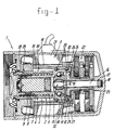
- the actuator shown in figures 1 and 2 comprises a housing 1 containing a screw mechanism 2 and a motor 3.
- Said screw mechanism 2 comprises a nut 4 and a screw 5, provided with screw threads 6, 7 and which engage each other by means of a number of balls 8. At the location of the inserts 9, the balls are transferred between adjacent windings of the screw threads 6, 7.
- the screw is integrated with the outer ring 10 of support bearing 11.
- the outer ring 10 has a larger diameter than the screw 5, for reasons of compactness of the actuator.
- the inner ring 12 of the support bearing 11 is integrated with a ball joint 13.
- the inner ring has a spherical inner surface 14, which engages a ball 15 connected to the central support shaft 16.
- the ball 15 is depicted as a separate part, it may also be carried out in one piece with the central support shaft 16.
- the central support shaft 16 is connected to the housing through the clip ring arrangement 17, and load cell 18 for measuring axial forces.
- the rotor 19 of the motor 3 is supported with respect to the outer ring of the support bearing 11 by means of a sleeve 31 having integrated bearings 20. Said sleeve 31 is fixed to the stator 21.
- the stator 21 of the motor 3 is fixably connected to the housing 1. Furthermore, the sleeve 31 is fixed to sleeve 32 of a reduction gear wheel mechanism 22.
- the motor 3 drives the sleeve 23, which carries an outwardly toothed member.
- This outwardly tooth member has teeth 25, which have a curved shape.
- the outer ring 10 of the support bearing 11 carries an inwardly toothed member 26, which carries inwardly directed teeth with a correspondingly curved shape.
- outwardly directed teeth 25 and inwardly directed teeth 27 are equal. These teeth engage each other so as to transfer the driving action from the sleeve 23 onto the screw 5.
- the nut 4 is carried out as a piston which is slidably held in a cylindrical space 28 in the housing 1.
- said cylinder is held axially movable, but non-rotatable within the cylinder space 28.
- the nut Upon actuating the screw 5, the nut is therefore driven linearly and in axial direction with respect to the housing 1, e.g. for driving the brake pads of a brake calliper (not shown) towards and from each other.
- FIG. 3 shows a brake calliper 40, comprising a housing 1 connected to claw piece 41 by means of screw thread. At its side facing the actuator 1, the claw piece 41 has a cavity 43 in which part of the stator 21 of motor 3 has been accommodated. Thereby, a very compact brake calliper 40 is obtained.
- the claw piece 41 has a fixed brake pad 44 as well as a movable brake pad 45 which is connected to the nut 5 of the screw mechanism 2, in particular to the head 46 thereof.
- the support shaft 16 supports the support bearing 11, the inner ring 12 thereof being fixedly connected by means of e.g. a clip ring 48.
- the inner ring 12 of support bearing 11 has a closed head 49, such that a load cell 50 can be accommodated between said closed head 49 and the facing end of support shaft 16.
- the external teeth 25 of the externally toothed member 24 are rounded off in longitudinal cross-section, so as to better allow bending deformations of the housing, without however transferring the bending action onto the screw mechanism 2.
- a grease-dosing unit 53 is accommodated in the base of the screw 5.
Landscapes
- Engineering & Computer Science (AREA)
- General Engineering & Computer Science (AREA)
- Mechanical Engineering (AREA)
- Power Engineering (AREA)
- Transmission Devices (AREA)
- Connection Of Motors, Electrical Generators, Mechanical Devices, And The Like (AREA)
- Braking Arrangements (AREA)
Abstract
Description
Claims (33)
- Actuator, comprising a housing (1) accommodating a screw mechanism (2) and a drive comprising a motor (3), said screw mechanism (2) comprising a nut (4) and a screw (5) one of which is rotatably supported with respect to the housing (1), such that upon relative rotation of the nut (4) and the screw (5) a linear movement of one of said nut (4) and screw (5) is obtained, characterised in that at least a rotatable component of the drive, e.g. the rotor (19) of the motor (3), is rotatably supported on the screw (5) which is rotatably supported with respect to the housing.
- Actuator according to claim 1, wherein the screw (5) is rotatably supported with respect to the housing (1) by means of a support bearing (11).
- Actuator according to claim 2, wherein the rotatable component of the drive, e.g. the rotor (19) of the motor (3) is rotatably supported on the screw (5) by means of an auxiliary bearing (52).
- Actuator according to claim 3, wherein the support bearing (11) is accommodated within the auxiliary bearing (52).
- Actuator according to claim 2, 3 or 4, wherein the screw (5) is integrated with the outer ring (10) of the support bearing (11).
- Actuator according to claim 5, wherein the outer diameter of the outer ring (10) of the support bearing (11) is larger than the outer diameter of the screw (5).
- Actuator according to any of claims 2 - 6, wherein the outer ring (10) of the bearing (11) supports a rotatable sleeve (31) which is in connection with the rotatable component (19) of the drive.
- Actuator according to claim 7, wherein the sleeve (31) comprises, or is connected to, the integrated outer ring of an auxiliary bearing, the inner ring of which is integrated with the outer ring (10) of the support bearing (11).
- Actuator according to claim 8, wherein the sleeve (31) comprises two axially spaced raceways, each of said raceways engaging a number of rolling elements (20) which each engage a raceway on the outer surface of the outer ring (10) of the support bearing (11).
- Actuator according to claim 7, 8 or 9, wherein the sleeve (31) is connected to the rotor (19) of the motor (3).
- Actuator according to any of the preceding claims, wherein one of the nut (4) and screw (5) is rotatably supported both according to an axis parallel with respect to said linear movement, and according to at least one axis transverse with respect to said linear movement.
- Actuator according to claim 11, wherein one of the nut (4) and screw (5) is supported with respect to the housing by means of a ball joint (13).
- Actuator according to claim 12, wherein the ball joint (13) is at one end of a central support shaft (16), the other end of which is connected to the housing (1).
- Actuator according to claim 13, wherein the ball joint (12) is connected to a support bearing (11), said support bearing (11) supporting the screw (5), said one of the nut (4) and the screw (5) being drivably connected to the rotor (19) of the motor (3).
- Actuator according to claim 14, wherein said one of the nut (4) and the screw (5) engages the rotor (19) through a coupling (25, 27) which allows rotations about at least one axis transverse with relation to the linear movement.
- Actuator according to claim 15, wherein the coupling comprises an internally toothed member (26) as well as an externally toothed member (24) having equal number of teeth (25, 27).
- Actuator according to claim 16, wherein the teeth (25) of the externally toothed member (24) are convexly curved in a cross-section parallel to the linear movement.
- Actuator according to claim 16 or 17, wherein the teeth of the externally toothed member (24) are centred with respect to the ball joint (13).
- Actuator according to any of claims 14-18, wherein the screw (5) is integrated with the outer ring (10) of the support bearing (11).
- Actuator according to claim 19, wherein the outer diameter of the outer ring (10) of the support bearing (11) is larger than the outer diameter of the screw (5).
- Actuator according to claim 19 or 20, wherein the outer ring (10) of the support bearing (11) is integrated with an internally toothed member (26).
- Actuator according to claim 20, wherein the screw (5) and the internally toothed member (26) are at axially opposite ends of the outer ring (10) of the support bearing (11).
- Actuator according to any of claims 19-22, wherein the rotor (19) of the motor (3) is rotatably supported on the outer ring of the support bearing (11).
- Actuator according to claim 23, wherein the rotor (19) engages an externally toothed member (24) through a reduction gear mechanism (22).
- Actuator according to claim 24, wherein the support bearing (11) is supported on one end of a support shaft (16), the other end of which is connected to the housing (1), the externally toothed member (24) being rotatably supported on said support shaft (16).
- Actuator according to claim 19 or 20, wherein the rotor (19) of the motor (3) directly engages the outer ring (10) of the support bearing (11).
- Actuator according to claim 26, wherein the rotor (19) is integrated with an internally toothed member, and the outer ring (10) of the support bearing (11) is integrated with an externally toothed member, said members engaging each other.
- Actuator according to claims 13-27, wherein the screw (5) and the support shaft (16) each have a throughgoing bore, said bores being aligned with respect to each other.
- Actuator according to any of claims 1-28, wherein the screw (5) comprises a bore, said bore containing a grease dosing unit (53).
- Actuator according to any of the preceding claims, wherein at least one of the components of the screw mechanism (2), support bearing (11), auxiliary bearing (52) and reduction gear mechanism (22) comprises a surface obtained by hard turning.
- Actuator according to any of the preceding claims, wherein at least one of the components of the screw mechanism (2), support bearing (11), auxiliary bearing (52) and reduction gear mechanism (22) comprises a coating, e.g. a diamond-like carbon coating.
- Actuator according to any of the preceding claims, wherein an encoder is provided for measuring a relative rotation.
- Brake calliper for a disc brake, comprising a claw piece (41) carrying at least two opposite brake pads (44, 45) which enclose a gap for accommodating a brake disc (47), and an actuator according to any of the preceding claims, said actuator having a housing (1) accommodating a screw mechanism (2) and a drive comprising a motor (3), said screw mechanism (2) comprising a nut (4) and a screw (5) one of which is rotatably supported with respect to the housing (1), such that upon relative rotation of the nut (4) and the screw (5) a linear movement of one of said nut (4) and screw (5) is obtained, said housing (1) being connected to the claw piece (41), characterised in that at least a rotatable component of the drive, e.g. the rotor (19) of the motor (3), is rotatably supported on the screw (5) which is rotatably supported with respect to the housing.
Applications Claiming Priority (3)
| Application Number | Priority Date | Filing Date | Title |
|---|---|---|---|
| NL1011142 | 1999-01-27 | ||
| NL1011142A NL1011142C2 (en) | 1999-01-27 | 1999-01-27 | Compact actuator. |
| PCT/NL2000/000053 WO2000045064A1 (en) | 1999-01-27 | 2000-01-27 | Compact actuator |
Publications (2)
| Publication Number | Publication Date |
|---|---|
| EP1147328A1 EP1147328A1 (en) | 2001-10-24 |
| EP1147328B1 true EP1147328B1 (en) | 2003-07-16 |
Family
ID=19768551
Family Applications (1)
| Application Number | Title | Priority Date | Filing Date |
|---|---|---|---|
| EP00903041A Expired - Lifetime EP1147328B1 (en) | 1999-01-27 | 2000-01-27 | Compact actuator |
Country Status (9)
| Country | Link |
|---|---|
| US (1) | US6907967B1 (en) |
| EP (1) | EP1147328B1 (en) |
| JP (1) | JP2002535581A (en) |
| KR (1) | KR20010093284A (en) |
| CN (1) | CN1191436C (en) |
| AU (1) | AU2467600A (en) |
| DE (1) | DE60003887T2 (en) |
| NL (1) | NL1011142C2 (en) |
| WO (1) | WO2000045064A1 (en) |
Cited By (2)
| Publication number | Priority date | Publication date | Assignee | Title |
|---|---|---|---|---|
| DE102005054912A1 (en) * | 2005-11-17 | 2007-05-24 | Minebea Co., Ltd. | Linear actuator for use in automotive applications, has rotor with permanent magnets, where rotary movement of rotor is converted into linear movement of positioning rod, and stator coils are arranged coaxial to magnets in axial direction |
| DE102021119258A1 (en) | 2021-07-26 | 2023-01-26 | Schaeffler Technologies AG & Co. KG | Linear actuator with force sensors |
Families Citing this family (37)
| Publication number | Priority date | Publication date | Assignee | Title |
|---|---|---|---|---|
| US6767305B2 (en) | 2000-03-27 | 2004-07-27 | Continental Teves Ag & Co., Ohg | Actuating unit |
| DE10114471A1 (en) * | 2001-03-24 | 2002-09-26 | Bosch Gmbh Robert | Coupling transferring rotary motion for brake actuating device in vehicle has free rotation angle in at least one direction of rotation and rotary stop that limits free rotation angle |
| GB0116674D0 (en) * | 2001-07-07 | 2001-08-29 | Lucas Industries Ltd | Screw actuator |
| ITTO20011163A1 (en) * | 2001-12-13 | 2003-06-13 | Skf Ind Spa | SCREW ACTUATOR WITH FIXED MOTOR SCREW. |
| ITTO20021104A1 (en) * | 2002-12-20 | 2004-06-21 | Skf Ind Spa | ELECTROMECHANICAL SCREW ACTUATOR GROUP |
| US20050247529A1 (en) * | 2004-05-07 | 2005-11-10 | Gaines Louie T | Aircraft brake acuation system including an internally threaded ballscrew actuator assembly |
| JP4602190B2 (en) * | 2005-08-04 | 2010-12-22 | 日信工業株式会社 | Vehicle disc brake |
| DE102006037660A1 (en) * | 2005-11-04 | 2007-07-19 | Continental Teves Ag & Co. Ohg | Hydraulic vehicle brake with integrated electric motor-operated parking brake |
| JP4826942B2 (en) * | 2006-03-31 | 2011-11-30 | 日立オートモティブシステムズ株式会社 | Electric disc brake and electric disc brake assembly method |
| DE102009010085B3 (en) * | 2009-02-24 | 2010-07-01 | Saia-Burgess Dresden Gmbh | A linear actuator |
| KR20110124818A (en) * | 2010-05-12 | 2011-11-18 | 주식회사 만도 | Electric disc brake |
| DE102011050448A1 (en) * | 2011-05-18 | 2012-11-22 | Zf Lenksysteme Gmbh | Ball Screw, particularly for steering of motor vehicle, has ball screw spindle, ball screw nut, bearing for ball screw spindle and bearing for ball screw nut |
| US9638300B2 (en) * | 2013-10-31 | 2017-05-02 | Goodrich Corporation | Electromechanical actuator proximal position stopping assembly |
| EP3173665B1 (en) * | 2014-07-17 | 2019-03-13 | SMC Corporation | Electric actuator |
| EP3193031B1 (en) * | 2014-09-11 | 2019-07-10 | SMC Corporation | Linear guide device and actuator |
| JP6478571B2 (en) * | 2014-11-12 | 2019-03-06 | Ntn株式会社 | Electric linear actuator and electric brake device |
| DE102015206735B3 (en) * | 2015-04-15 | 2016-05-19 | Schaeffler Technologies AG & Co. KG | Actuator with planetary roller screw drive |
| US20170045105A1 (en) * | 2015-08-04 | 2017-02-16 | Persimmon Technologies, Corp. | Electric Brake Caliper |
| GB201515843D0 (en) * | 2015-09-07 | 2015-10-21 | Trw Ltd | An electromechanical actuator |
| GB201515845D0 (en) * | 2015-09-07 | 2015-10-21 | Trw Ltd | An electromechanical actuator |
| JP6765193B2 (en) * | 2016-01-27 | 2020-10-07 | Ntn株式会社 | Electric actuator |
| JP6678039B2 (en) * | 2016-02-10 | 2020-04-08 | Ntn株式会社 | Electric brake device |
| JP6671209B2 (en) * | 2016-03-28 | 2020-03-25 | Ntn株式会社 | Electric actuator |
| DE102016207634B4 (en) * | 2016-05-03 | 2025-11-06 | Valeo Eautomotive Germany Gmbh | Rotating electric machine |
| US20190203825A1 (en) * | 2016-05-27 | 2019-07-04 | Nidec Corporation | Actuator |
| JP6838935B2 (en) * | 2016-10-31 | 2021-03-03 | Ntn株式会社 | Electric actuator |
| CN108667210B (en) * | 2018-06-29 | 2024-08-27 | 无锡新宏泰电器科技股份有限公司 | Braking type motor |
| DE102018123039A1 (en) * | 2018-09-19 | 2020-03-19 | Fte Automotive Gmbh | Electrical clutch actuator with a one-piece housing |
| DE102018123045A1 (en) * | 2018-09-19 | 2020-03-19 | Fte Automotive Gmbh | Electric clutch actuator with gearbox bearing plate |
| JP7131329B2 (en) * | 2018-11-21 | 2022-09-06 | トヨタ自動車株式会社 | brake actuator |
| CN110775786B (en) * | 2019-11-21 | 2020-12-01 | 江西特种电机股份有限公司 | Novel inner rotor traction machine structure |
| KR20230065511A (en) * | 2021-11-05 | 2023-05-12 | 현대모비스 주식회사 | Brake apparatus for vehicle |
| DE102022119395A1 (en) | 2021-11-17 | 2023-05-17 | Zf Active Safety Gmbh | Brake actuator unit and electromechanical brake |
| JP7338810B1 (en) * | 2022-01-05 | 2023-09-05 | 日本精工株式会社 | BALL SCREW DEVICE AND SCREW SHAFT MANUFACTURING METHOD |
| CN117469327A (en) * | 2022-07-22 | 2024-01-30 | 本田技研工业株式会社 | Electric braking device and manufacturing method thereof |
| KR20240087067A (en) * | 2022-12-12 | 2024-06-19 | 현대모비스 주식회사 | Brake device |
| DE102024209664A1 (en) | 2024-10-02 | 2026-04-02 | Robert Bosch Gesellschaft mit beschränkter Haftung | Electromechanical brake with anti-rotation device |
Family Cites Families (16)
| Publication number | Priority date | Publication date | Assignee | Title |
|---|---|---|---|---|
| US4180146A (en) * | 1978-03-13 | 1979-12-25 | Hurst Performance, Inc. | Brake assembly with dual compensation adjustment |
| FR2610053B1 (en) * | 1987-01-22 | 1989-03-31 | Bendix France | METHOD AND DEVICE FOR ACTUATING A BRAKING MECHANISM BY A ROTARY ELECTRIC MOTOR |
| DE3836255A1 (en) * | 1988-10-25 | 1990-04-26 | Opel Adam Ag | ELECTRIC MOTOR ACTUATOR |
| FR2675450B1 (en) * | 1991-04-19 | 1993-08-06 | Aerospatiale | MULTIPLE DISC BRAKING DEVICE. |
| US5348123A (en) * | 1991-09-02 | 1994-09-20 | Akebono Brake Industry Co., Ltd. | Brake actuating apparatus for a vehicle |
| ES2151976T3 (en) * | 1995-05-19 | 2001-01-16 | Continental Ag | BRAKE ACTUATOR FOR A VEHICLE ELECTRIC DRIVE BRAKE. |
| DE19781587T1 (en) * | 1996-02-15 | 1999-04-15 | Kelsey Hayes Co | Electric disc brake actuation mechanism |
| DE19652230A1 (en) * | 1996-12-16 | 1998-06-18 | Teves Gmbh Alfred | Electromechanically actuated disc brake |
| NL1006540C2 (en) * | 1997-07-10 | 1999-01-15 | Skf Ind Trading & Dev | Electric actuator with control sensor, as well as disc brake comprising such an actuator. |
| JPH11147465A (en) * | 1997-11-17 | 1999-06-02 | Akebono Brake Ind Co Ltd | Hydraulic pressure control device and brake device using it |
| US6367592B1 (en) * | 1998-01-20 | 2002-04-09 | Skf Engineering And Research Centre B.V. | Modular actuator, and brake caliper comprising such actuator |
| DE19807328C2 (en) * | 1998-02-20 | 2003-08-28 | Lucas Ind Plc | Electromechanically actuated disc brake |
| US6325182B1 (en) * | 1998-03-27 | 2001-12-04 | Tokico, Ltd. | Motor-driven brake system |
| JP3911656B2 (en) * | 1998-03-30 | 2007-05-09 | 株式会社日立製作所 | Disc brake |
| US6139460A (en) * | 1999-05-24 | 2000-10-31 | Delphi Technologies, Inc. | Electric caliper |
| US6367593B1 (en) * | 2001-08-22 | 2002-04-09 | Delphi Technologies, Inc. | Electric caliper having splined ball screw |
-
1999
- 1999-01-27 NL NL1011142A patent/NL1011142C2/en not_active IP Right Cessation
-
2000
- 2000-01-27 DE DE60003887T patent/DE60003887T2/en not_active Expired - Fee Related
- 2000-01-27 KR KR1020017009463A patent/KR20010093284A/en not_active Abandoned
- 2000-01-27 AU AU24676/00A patent/AU2467600A/en not_active Abandoned
- 2000-01-27 JP JP2000596283A patent/JP2002535581A/en active Pending
- 2000-01-27 WO PCT/NL2000/000053 patent/WO2000045064A1/en not_active Ceased
- 2000-01-27 US US09/889,932 patent/US6907967B1/en not_active Expired - Fee Related
- 2000-01-27 EP EP00903041A patent/EP1147328B1/en not_active Expired - Lifetime
- 2000-01-27 CN CNB008032491A patent/CN1191436C/en not_active Expired - Fee Related
Cited By (3)
| Publication number | Priority date | Publication date | Assignee | Title |
|---|---|---|---|---|
| DE102005054912A1 (en) * | 2005-11-17 | 2007-05-24 | Minebea Co., Ltd. | Linear actuator for use in automotive applications, has rotor with permanent magnets, where rotary movement of rotor is converted into linear movement of positioning rod, and stator coils are arranged coaxial to magnets in axial direction |
| DE102005054912B4 (en) * | 2005-11-17 | 2009-01-08 | Minebea Co., Ltd. | Linear Actuator |
| DE102021119258A1 (en) | 2021-07-26 | 2023-01-26 | Schaeffler Technologies AG & Co. KG | Linear actuator with force sensors |
Also Published As
| Publication number | Publication date |
|---|---|
| US6907967B1 (en) | 2005-06-21 |
| CN1191436C (en) | 2005-03-02 |
| DE60003887D1 (en) | 2003-08-21 |
| CN1339092A (en) | 2002-03-06 |
| AU2467600A (en) | 2000-08-18 |
| JP2002535581A (en) | 2002-10-22 |
| DE60003887T2 (en) | 2004-01-22 |
| NL1011142C2 (en) | 2000-07-31 |
| EP1147328A1 (en) | 2001-10-24 |
| WO2000045064A1 (en) | 2000-08-03 |
| KR20010093284A (en) | 2001-10-27 |
Similar Documents
| Publication | Publication Date | Title |
|---|---|---|
| US6907967B1 (en) | Compact actuator | |
| EP1232347B1 (en) | Actuator with misalignment compensation | |
| US6767305B2 (en) | Actuating unit | |
| US6763918B1 (en) | Actuator having compact gear reduction | |
| KR100544081B1 (en) | Electric actuators and caliper brakes with such actuators | |
| EP1080318B1 (en) | Screw actuator, and brake calliper comprising such actuator | |
| EP1230493B1 (en) | Actuator having a central support, and brake calliper comprising such actuator | |
| US20100320043A1 (en) | Electric linear motion actuator and electric brake assembly | |
| PL177962B1 (en) | Bowden cable coupler | |
| KR20060122808A (en) | Actuator and Brake Assembly | |
| CN103348163A (en) | Electric linear actuator and electric disc brake device | |
| KR100566367B1 (en) | An actuator comprising a flexible element and a brake caliper comprising such an actuator | |
| US7007775B2 (en) | Screw actuator with a fixed nut | |
| KR20020059680A (en) | Actuator comprising a sleeve support | |
| US6527448B1 (en) | Asymmetric angular contact bearing | |
| EP1461543B1 (en) | Screw actuator module | |
| JP5440923B2 (en) | Electric linear actuator and electric brake device | |
| JP7768264B2 (en) | Ball screw device | |
| US20250115227A1 (en) | Actuator assembly | |
| CN121443494A (en) | Ball screw nuts with a central flange for caliper brakes |
Legal Events
| Date | Code | Title | Description |
|---|---|---|---|
| PUAI | Public reference made under article 153(3) epc to a published international application that has entered the european phase |
Free format text: ORIGINAL CODE: 0009012 |
|
| 17P | Request for examination filed |
Effective date: 20010727 |
|
| AK | Designated contracting states |
Kind code of ref document: A1 Designated state(s): AT BE CH CY DE DK ES FI FR GB GR IE IT LI LU MC NL PT SE |
|
| GRAH | Despatch of communication of intention to grant a patent |
Free format text: ORIGINAL CODE: EPIDOS IGRA |
|
| GRAH | Despatch of communication of intention to grant a patent |
Free format text: ORIGINAL CODE: EPIDOS IGRA |
|
| GRAA | (expected) grant |
Free format text: ORIGINAL CODE: 0009210 |
|
| AK | Designated contracting states |
Designated state(s): DE ES FR GB IT |
|
| REG | Reference to a national code |
Ref country code: GB Ref legal event code: FG4D |
|
| RIN1 | Information on inventor provided before grant (corrected) |
Inventor name: KAPAAN, HENDRIKUS, JAN Inventor name: FUCKS, THOMAS, WILHELM Inventor name: VAN WINDEN, JOHANNES, ALBERTUS Inventor name: ZWARTS, JACOBUS |
|
| REG | Reference to a national code |
Ref country code: IE Ref legal event code: FG4D |
|
| REF | Corresponds to: |
Ref document number: 60003887 Country of ref document: DE Date of ref document: 20030821 Kind code of ref document: P |
|
| PG25 | Lapsed in a contracting state [announced via postgrant information from national office to epo] |
Ref country code: ES Free format text: LAPSE BECAUSE OF FAILURE TO SUBMIT A TRANSLATION OF THE DESCRIPTION OR TO PAY THE FEE WITHIN THE PRESCRIBED TIME-LIMIT Effective date: 20031027 |
|
| ET | Fr: translation filed | ||
| PLBE | No opposition filed within time limit |
Free format text: ORIGINAL CODE: 0009261 |
|
| STAA | Information on the status of an ep patent application or granted ep patent |
Free format text: STATUS: NO OPPOSITION FILED WITHIN TIME LIMIT |
|
| 26N | No opposition filed |
Effective date: 20040419 |
|
| REG | Reference to a national code |
Ref country code: IE Ref legal event code: MM4A |
|
| PGFP | Annual fee paid to national office [announced via postgrant information from national office to epo] |
Ref country code: FR Payment date: 20060117 Year of fee payment: 7 |
|
| PGFP | Annual fee paid to national office [announced via postgrant information from national office to epo] |
Ref country code: DE Payment date: 20060228 Year of fee payment: 7 |
|
| PG25 | Lapsed in a contracting state [announced via postgrant information from national office to epo] |
Ref country code: DE Free format text: LAPSE BECAUSE OF NON-PAYMENT OF DUE FEES Effective date: 20070801 |
|
| GBPC | Gb: european patent ceased through non-payment of renewal fee |
Effective date: 20070127 |
|
| REG | Reference to a national code |
Ref country code: FR Ref legal event code: ST Effective date: 20070930 |
|
| PG25 | Lapsed in a contracting state [announced via postgrant information from national office to epo] |
Ref country code: GB Free format text: LAPSE BECAUSE OF NON-PAYMENT OF DUE FEES Effective date: 20070127 |
|
| PGFP | Annual fee paid to national office [announced via postgrant information from national office to epo] |
Ref country code: IT Payment date: 20070518 Year of fee payment: 8 |
|
| PG25 | Lapsed in a contracting state [announced via postgrant information from national office to epo] |
Ref country code: FR Free format text: LAPSE BECAUSE OF NON-PAYMENT OF DUE FEES Effective date: 20070131 |
|
| PGFP | Annual fee paid to national office [announced via postgrant information from national office to epo] |
Ref country code: GB Payment date: 20060119 Year of fee payment: 7 |
|
| PG25 | Lapsed in a contracting state [announced via postgrant information from national office to epo] |
Ref country code: IT Free format text: LAPSE BECAUSE OF NON-PAYMENT OF DUE FEES Effective date: 20080127 |