EP1146503A2 - Active noise cancellation optimized air gaps - Google Patents
Active noise cancellation optimized air gaps Download PDFInfo
- Publication number
- EP1146503A2 EP1146503A2 EP01201079A EP01201079A EP1146503A2 EP 1146503 A2 EP1146503 A2 EP 1146503A2 EP 01201079 A EP01201079 A EP 01201079A EP 01201079 A EP01201079 A EP 01201079A EP 1146503 A2 EP1146503 A2 EP 1146503A2
- Authority
- EP
- European Patent Office
- Prior art keywords
- speaker
- mouth
- sound
- louder
- air induction
- Prior art date
- Legal status (The legal status is an assumption and is not a legal conclusion. Google has not performed a legal analysis and makes no representation as to the accuracy of the status listed.)
- Granted
Links
Images

Classifications
-
- F—MECHANICAL ENGINEERING; LIGHTING; HEATING; WEAPONS; BLASTING
- F02—COMBUSTION ENGINES; HOT-GAS OR COMBUSTION-PRODUCT ENGINE PLANTS
- F02M—SUPPLYING COMBUSTION ENGINES IN GENERAL WITH COMBUSTIBLE MIXTURES OR CONSTITUENTS THEREOF
- F02M35/00—Combustion-air cleaners, air intakes, intake silencers, or induction systems specially adapted for, or arranged on, internal-combustion engines
- F02M35/12—Intake silencers ; Sound modulation, transmission or amplification
- F02M35/1244—Intake silencers ; Sound modulation, transmission or amplification using interference; Masking or reflecting sound
- F02M35/125—Intake silencers ; Sound modulation, transmission or amplification using interference; Masking or reflecting sound by using active elements, e.g. speakers
-
- G—PHYSICS
- G10—MUSICAL INSTRUMENTS; ACOUSTICS
- G10K—SOUND-PRODUCING DEVICES; METHODS OR DEVICES FOR PROTECTING AGAINST, OR FOR DAMPING, NOISE OR OTHER ACOUSTIC WAVES IN GENERAL; ACOUSTICS NOT OTHERWISE PROVIDED FOR
- G10K11/00—Methods or devices for transmitting, conducting or directing sound in general; Methods or devices for protecting against, or for damping, noise or other acoustic waves in general
- G10K11/16—Methods or devices for protecting against, or for damping, noise or other acoustic waves in general
- G10K11/175—Methods or devices for protecting against, or for damping, noise or other acoustic waves in general using interference effects; Masking sound
- G10K11/178—Methods or devices for protecting against, or for damping, noise or other acoustic waves in general using interference effects; Masking sound by electro-acoustically regenerating the original acoustic waves in anti-phase
- G10K11/1785—Methods, e.g. algorithms; Devices
- G10K11/17857—Geometric disposition, e.g. placement of microphones
-
- G—PHYSICS
- G10—MUSICAL INSTRUMENTS; ACOUSTICS
- G10K—SOUND-PRODUCING DEVICES; METHODS OR DEVICES FOR PROTECTING AGAINST, OR FOR DAMPING, NOISE OR OTHER ACOUSTIC WAVES IN GENERAL; ACOUSTICS NOT OTHERWISE PROVIDED FOR
- G10K11/00—Methods or devices for transmitting, conducting or directing sound in general; Methods or devices for protecting against, or for damping, noise or other acoustic waves in general
- G10K11/16—Methods or devices for protecting against, or for damping, noise or other acoustic waves in general
- G10K11/175—Methods or devices for protecting against, or for damping, noise or other acoustic waves in general using interference effects; Masking sound
- G10K11/178—Methods or devices for protecting against, or for damping, noise or other acoustic waves in general using interference effects; Masking sound by electro-acoustically regenerating the original acoustic waves in anti-phase
- G10K11/1787—General system configurations
-
- G—PHYSICS
- G10—MUSICAL INSTRUMENTS; ACOUSTICS
- G10K—SOUND-PRODUCING DEVICES; METHODS OR DEVICES FOR PROTECTING AGAINST, OR FOR DAMPING, NOISE OR OTHER ACOUSTIC WAVES IN GENERAL; ACOUSTICS NOT OTHERWISE PROVIDED FOR
- G10K2210/00—Details of active noise control [ANC] covered by G10K11/178 but not provided for in any of its subgroups
- G10K2210/10—Applications
- G10K2210/128—Vehicles
- G10K2210/1282—Automobiles
-
- G—PHYSICS
- G10—MUSICAL INSTRUMENTS; ACOUSTICS
- G10K—SOUND-PRODUCING DEVICES; METHODS OR DEVICES FOR PROTECTING AGAINST, OR FOR DAMPING, NOISE OR OTHER ACOUSTIC WAVES IN GENERAL; ACOUSTICS NOT OTHERWISE PROVIDED FOR
- G10K2210/00—Details of active noise control [ANC] covered by G10K11/178 but not provided for in any of its subgroups
- G10K2210/30—Means
- G10K2210/321—Physical
- G10K2210/3214—Architectures, e.g. special constructional features or arrangements of features
-
- G—PHYSICS
- G10—MUSICAL INSTRUMENTS; ACOUSTICS
- G10K—SOUND-PRODUCING DEVICES; METHODS OR DEVICES FOR PROTECTING AGAINST, OR FOR DAMPING, NOISE OR OTHER ACOUSTIC WAVES IN GENERAL; ACOUSTICS NOT OTHERWISE PROVIDED FOR
- G10K2210/00—Details of active noise control [ANC] covered by G10K11/178 but not provided for in any of its subgroups
- G10K2210/30—Means
- G10K2210/321—Physical
- G10K2210/3219—Geometry of the configuration
Definitions
- This invention relates to an active control of automotive induction noise.
- Active systems use a speaker to create a sound that attenuates engine noise.
- the sound created is out of phase with the engine noise and combines with the engine noise to result in its reduction.
- this sound is generated in proximity to the air induction system.
- the speaker is placed in the mouth of air intake duct.
- Air ducts frequently have a non-round mouth such as an ellipse shape.
- the speakers used in such systems may also have a non-round shape to conform to the shape of the mouth of the air duct.
- Non-round speakers have varying levels of sound generation quality due to their shape. That is, a non-round speaker will create a louder sound in some portions of the speaker than in other portions because of its dimensions. For example, a speaker in the shape of an ellipse will radiate sound louder at the points of the ellipse than on the sides of the ellipse. Due to this uneven sound production, the use of a non-round speak may result in a less than optimal attenuation of engine noise emanating from the mouth of the air induction system.
- the acoustic system comprises a mouth of an air induction body of an air induction system and a speaker disposed about the mouth.
- the mouth emanates a noise to be cancelled by a sound from the speaker.
- the mouth has at least a first mouth portion and at least a second mouth portion.
- the noise is louder at the first mouth portion than at the second mouth portion.
- the speaker generates a canceling sound and has at least a first speaker portion and at least a second speaker portion. The canceling sound is louder at the first speaker portion than at the second speaker portion.
- the speaker is arranged about the mouth so that the first speaker portion, the louder speaker portion, is associated with the first mouth portion, the louder mouth portion.
- the speaker is also arranged so that the second speaker portion is associated with the second mouth portion.
- the canceling sound is preferably out of phase with the engine noise to promote noise attenuation. In this arrangement, the more effective portion of the speaker is associated with the louder portion of the mouth to thereby improve engine noise attenuation.
- the mouth and speaker are elliptical in shape, the mouth is widened at portions closest to the louder portions of the speaker and narrowed at portions closest to the quieter portions of the speaker.
- Such a design also permits greater airflow through the air induction body than if the mouth and speaker had a uniform shape.
- other non-round speaker shapes can be optimized with an air duct mouth.
- the invention may serve to amplify sound from a source. In such an arrangement, the sound from the speaker is in phase with the sound from the mouth and the louder portions of the speaker are associated with the louder portions of the mouth.
- a first sound emanates from a mouth with at least a first mouth portion and at least a second mouth portion wherein the first sound is louder at the first mouth portion than at the second mouth portion.
- a second sound is generated from a speaker disposed about the mouth and has at least a first speaker portion and at least a second speaker portion wherein the second sound is louder at the first speaker portion than at the second speaker portion. The synchronization of the phase of sounds will determine whether the sounds are amplified or attenuated.
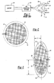
- Figure 1 shows a side view of a speaker in the mouth of an air induction system as known in the art.
- Figure 2 shows a front view of Figure 1, including the speaker and the mouth of the air induction system, as known.
- Figure 3 shows a front view of an embodiment of the invention, including elliptical speaker and an elliptical mouth of the air induction system.
- Figure 4 shows another view of the embodiment of Figure 3.
- Figure 5 shows another embodiment of the invention, including another non-round speaker and non-round mouth.
- Figure 1 illustrates a noise attenuation system known in the art. Shown are speaker 10, mouth 14, air induction body 18, air induction system 22 and engine 26. As known, air 18 travels through mouth 14, air induction body 18, and air induction system 22 to engine 26 to provide air for the engine's cylinders. Conversely, engine noise 34 travels from engine 26 through air induction system 22, air induction body 18, and out of mouth 14. Speaker 10 creates canceling sound 38, which is a sound wave that is out of phase with engine noise 34. It is known in the prior art that the face of speaker 10 is preferably in the same plane as mouth 14.
- Figure 2 represents a front view of speaker 10 and mouth 14 of Figure 1.
- speaker effectiveness is uniform around edge 46 of speaker 10.
- gap 42 between speaker 10 and mouth 14 is therefore of uniform width W.
- FIG 3 illustrates an embodiment of the invention.
- Speaker 48 an ellipse
- Mouth 52 is operatively connected to an air induction system as shown in Figure 1 and as known in the art. Because length L2 of speaker 48 is longer than L1, more air is compressed and sound generated at first speaker portion 60 along length L2 than at second speaker portion 64 along length L1. Thus, speaker 48 has a higher sound level at first speaker portion 60 than at second speaker portion 64.
- gap 56 between mouth 52 and speaker 48 is of non-uniform width as illustrated at X and Y, where width at X is greater than width at Y. Accordingly, first mouth portion 68 and second mouth portion 72 comprise gaps of differing widths as measured between speaker 48 and mouth 52. This arrangement permits more engine noise to emanate from mouth 56 at first mouth portion 68 than at second mouth portion 72.
- first speaker portion 60 is associated with first mouth portion 68 and second speaker portion 64 is associated with second mouth portion 72.
- the louder portions of speaker 48 are associated with the louder portions of mouth 52 while the quieter portions of speaker 48 are associated with the quieter portions of mouth 52.
- the more effective portions of speaker 48 are placed by the louder portions of mouth 52 while engine noise is minimized around the quieter portions of speaker 48.
- the sound from speaker 48 is preferably 180 degrees out of phase with engine noise to ensure destructive interference between the two sounds.
- the two sounds are thereby amplified rather than attenuated.
- Figure 4 illustrates a way to determine optimal spacing of gap 56 between speaker 48 and mouth 52. If area 76, a mouth portion, is delineated by points A, B, A1, and B1 and area 78, a speaker portion, is delineated by points B, C, B1, then the division of area 76 by area 78 creates a constant k. Constant k permits determination of the relationship between area 80 as delineated by points A1, B1, B2 and A2 and area 82 as delineated by points B1, C, and B2. This relationship is as follows:
- Constant k will relate areas 88 and 90 and 92 to 94 in the same way.
- k once known allows ideal determination of the spacing around the speaker.
- constant k may be multiplied by a factor related to wavelength of sound and width of gap to compensate for attenuation of sound due to small gap effects.
- Figure 5 illustrates another embodiment of the invention using a non-round speaker 98 with a non-round mouth 102. Again, gap 104 between speaker 98 and mouth 102 is of non-uniform width, permitting more noise to emanate around the more effective portions of speaker 98.
- a first sound emanates from a mouth with at least a first mouth portion and at least a second mouth portion wherein the first sound is louder at the first mouth portion than at the second mouth portion.
- a second sound also emanates from a speaker disposed about the mouth and has at least a first speaker portion and at least a second speaker portion wherein the second sound is louder at the first speaker portion than at the second speaker portion.
Landscapes
- Engineering & Computer Science (AREA)
- Physics & Mathematics (AREA)
- Acoustics & Sound (AREA)
- Multimedia (AREA)
- Chemical & Material Sciences (AREA)
- Combustion & Propulsion (AREA)
- Mechanical Engineering (AREA)
- General Engineering & Computer Science (AREA)
- Soundproofing, Sound Blocking, And Sound Damping (AREA)
Abstract
Description
Similarly,
Claims (16)
- An acoustic system comprising:a mouth (14) operable to create a first sound and with at least a first mouth portion (68) and at least a second mouth portion (72) wherein said first sound is louder at said at least first mouth portion (68) than at said at least second mouth portion(72); anda speaker (10) operable to create a second sound disposed about said mouth (14) and with at least a first speaker portion and at least a second speaker portion (64) wherein said second sound is louder at said at least first speaker portion (60) than at said at least second speaker portion(64).
- The acoustic system of claim 1 wherein said speaker (10) is arranged so that said at least first speaker portion (60) is associated with said at least first mouth portion (68).
- The acoustic system of claim 1 or 2 wherein said speaker (10) is arranged so that said at least second speaker portion (64) is associated with said at least second mouth portion (72).
- The acoustic system of one of the claims 1 to 3 wherein said first mouth portion (68) has a width between said speaker (10) and said mouth (14) different from a width between said speaker (10) and said mouth (14) of said second mouth portion(72).
- The acoustic system of one of the claims 1 to 4 wherein an area of said first mouth portion (68) is related to an area of said first speaker portion (60) so as to define a constant, said constant being used to relate said second mouth position to said second speaker position.
- The acoustic system of one of the claims 1 to 5 wherein said second sound is out of phase with said first sound to attenuate said first sound and said second sound.
- The acoustic system of one of the claims 1 to 6 wherein said second sound is in phase with said first sound to amplify said first sound and said second sound.
- The acoustic system of one of the claims 1 to 7 wherein said mouth (14) is operatively connected to an air induction system (22).
- An air induction system (22) comprising:an air induction body (18) having a mouth (14) operable to create a first sound and with at least a first mouth portion (68) and at least a second mouth portion (72) wherein said at least first sound is louder at said at least first mouth portion (68) than at said at least second mouth portion (72); anda speaker (10) operable to create a second sound disposed about said mouth (14) and with at least a first speaker portion (60) and at least a second speaker portion (64) wherein said second sound is louder at said at least first speaker portion (60) than at said at least second speaker portion (64) and wherein said second sound is out of phase with said first sound.
- The air induction system (22) of claim 9 wherein said speaker (10) is arranged so that said at least first speaker portion (60) is associated with said at least first mouth portion (68).
- The air induction system (22) of claim 9 or 10 wherein said speaker (10) is arranged so that said at least second speaker portion (64) is associated with said at least second mouth portion (72).
- The air induction system (22) of one of the claims 9 to 11 wherein said first mouth portion (68) has a width between said speaker (10) and said mouth (14) different from a width between said speaker (10) and said mouth (14) of said second mouth portion (72).
- The air induction system (22) of one of the claims 9 to 12 wherein said first mouth portion (68) is related to an area of said first speaker portion (60) so as to define a constant, said constant being used to relate said second mouth position to said second speaker position.
- A method of attenuating sound comprising the steps of:emanating a first sound from a mouth (14) of an air induction body (18) with at least a first mouth portion (68) and at least a second mouth portion (72) wherein the first sound is louder at the at least first mouth portion (68) than at the at least second mouth portion (72); andemanating a second sound from a speaker (10) disposed about the mouth (14) and with at least a first speaker portion (60) and at least a second speaker portion (64) wherein the said second sound is louder at the at least first speaker portion (60) than at the at least second speaker portion (64) and wherein the second sound is out of phase with the first sound.
- The method of claim 14 further wherein the speaker (10) is arranged so that the at least first speaker portion (60) is associated with the at least first mouth portion (68).
- The method of claim 14 or 15 wherein the speaker (10) is arranged so that the at least second speaker portion (64) is associated with the at least second mouth portion (72).
Applications Claiming Priority (5)
| Application Number | Priority Date | Filing Date | Title |
|---|---|---|---|
| US19713800P | 2000-04-14 | 2000-04-14 | |
| US197138P | 2000-04-14 | ||
| 2001-02-02 | |||
| US09/798,220 US20010046302A1 (en) | 2000-04-14 | 2001-03-02 | Active noise cancellation optimized air gaps |
| US798220P | 2001-03-02 |
Publications (3)
| Publication Number | Publication Date |
|---|---|
| EP1146503A2 true EP1146503A2 (en) | 2001-10-17 |
| EP1146503A3 EP1146503A3 (en) | 2004-11-03 |
| EP1146503B1 EP1146503B1 (en) | 2012-03-07 |
Family
ID=26892586
Family Applications (1)
| Application Number | Title | Priority Date | Filing Date |
|---|---|---|---|
| EP01201079A Expired - Lifetime EP1146503B1 (en) | 2000-04-14 | 2001-03-23 | Active noise cancellation optimized air gaps |
Country Status (2)
| Country | Link |
|---|---|
| US (1) | US20010046302A1 (en) |
| EP (1) | EP1146503B1 (en) |
Family Cites Families (31)
| Publication number | Priority date | Publication date | Assignee | Title |
|---|---|---|---|---|
| GB788327A (en) * | 1955-06-21 | 1957-12-23 | Gen Motors Ltd | Improvements in silencers for the air intakes of carburetters for internal combustion engines |
| US2890760A (en) * | 1956-08-16 | 1959-06-16 | Philco Corp | Transducers |
| US3936606A (en) * | 1971-12-07 | 1976-02-03 | Wanke Ronald L | Acoustic abatement method and apparatus |
| AU2342177A (en) * | 1976-03-22 | 1978-09-21 | Babbco Ltd | Loudspeaker. ribbed cone and bearing supported voice coil |
| GB2076049B (en) * | 1980-05-17 | 1983-10-26 | Rolls Royce | Variable acoustic impedance lining |
| US4665549A (en) * | 1985-12-18 | 1987-05-12 | Nelson Industries Inc. | Hybrid active silencer |
| GB8603678D0 (en) * | 1986-02-14 | 1986-03-19 | Gen Electric Co Plc | Active noise control |
| JP2945983B2 (en) * | 1987-03-25 | 1999-09-06 | 久次 中村 | Speaker device |
| JPH01245795A (en) * | 1988-03-28 | 1989-09-29 | Daikin Ind Ltd | electronic silencer |
| US5446790A (en) * | 1989-11-24 | 1995-08-29 | Nippondenso Co., Ltd. | Intake sound control apparatus |
| US5457749A (en) * | 1990-04-09 | 1995-10-10 | Noise Cancellation Technologies, Inc. | Electronic muffler |
| US5319165A (en) * | 1990-04-25 | 1994-06-07 | Ford Motor Company | Dual bandpass secondary source |
| US5229556A (en) * | 1990-04-25 | 1993-07-20 | Ford Motor Company | Internal ported band pass enclosure for sound cancellation |
| GB2252657A (en) * | 1990-10-24 | 1992-08-12 | Lotus Car | Vibration and sound generation in vehicles |
| JP2877982B2 (en) * | 1991-04-17 | 1999-04-05 | 本田技研工業株式会社 | Intake silencer |
| JP3094517B2 (en) * | 1991-06-28 | 2000-10-03 | 日産自動車株式会社 | Active noise control device |
| US5170019A (en) * | 1991-07-25 | 1992-12-08 | Lee Jung W | Sound muffling device for internal combustion engines |
| US5550334A (en) * | 1991-10-30 | 1996-08-27 | Noise Cancellation Technologies, Inc. | Actively sound reduced muffler having a venturi effect configuration |
| US5336856A (en) * | 1992-07-07 | 1994-08-09 | Arvin Industries, Inc. | Electronic muffler assembly with exhaust bypass |
| JPH06149268A (en) * | 1992-11-02 | 1994-05-27 | Fuji Heavy Ind Ltd | In-cabin noise reducing device |
| US5587563A (en) * | 1993-06-04 | 1996-12-24 | Dipti Kr. Datta | Air handling structure for pan inlet and outlet |
| US5446249A (en) * | 1993-07-13 | 1995-08-29 | Digisonix, Inc. | Dry acoustic system preventing condensation |
| DE4342133A1 (en) * | 1993-12-10 | 1995-06-14 | Nokia Deutschland Gmbh | Arrangement for active noise reduction |
| US5513266A (en) * | 1994-04-29 | 1996-04-30 | Digisonix, Inc. | Integral active and passive silencer |
| US5541373A (en) * | 1994-09-06 | 1996-07-30 | Digisonix, Inc. | Active exhaust silencer |
| US5693918A (en) * | 1994-09-06 | 1997-12-02 | Digisonix, Inc. | Active exhaust silencer |
| DE19531402C2 (en) * | 1995-08-26 | 1999-04-01 | Mannesmann Sachs Ag | Device and method for influencing vibrations in a passenger compartment of a motor vehicle and device and method for detecting defects in a motor vehicle |
| US5828759A (en) * | 1995-11-30 | 1998-10-27 | Siemens Electric Limited | System and method for reducing engine noise |
| US6084971A (en) * | 1997-06-10 | 2000-07-04 | Siemens Electric Limited | Active noise attenuation system |
| US6215885B1 (en) * | 1997-06-26 | 2001-04-10 | George R. Geiger | Audio speaker |
| JP3773667B2 (en) * | 1998-09-22 | 2006-05-10 | 小島プレス工業株式会社 | Hollow body |
-
2001
- 2001-03-02 US US09/798,220 patent/US20010046302A1/en not_active Abandoned
- 2001-03-23 EP EP01201079A patent/EP1146503B1/en not_active Expired - Lifetime
Also Published As
| Publication number | Publication date |
|---|---|
| US20010046302A1 (en) | 2001-11-29 |
| EP1146503A3 (en) | 2004-11-03 |
| EP1146503B1 (en) | 2012-03-07 |
Similar Documents
| Publication | Publication Date | Title |
|---|---|---|
| US5828759A (en) | System and method for reducing engine noise | |
| KR19990006829A (en) | Active noise attenuation system | |
| GB2245452A (en) | Active noise attenuation | |
| JP3822368B2 (en) | A shock absorber that reduces low-frequency sound generated at the entrance and exit of the tunnel | |
| JPH1039878A (en) | Noise reduction device for enclosed engine | |
| EP1146503A2 (en) | Active noise cancellation optimized air gaps | |
| JPH08314474A (en) | Active muffler | |
| JPH06332469A (en) | Method and device for active muffling for vehicle | |
| JPH09258745A (en) | Active silencer and active silencer design method | |
| JPH08232677A (en) | Surrounding engine noise reduction device | |
| WO2003028007A1 (en) | Modular active noise cancellation air filter speaker and microphone assembly | |
| US20030215101A1 (en) | Active noise control system with an elongated transmission member | |
| JP2006316724A (en) | Intake device and secondary sound generator | |
| JP3287467B2 (en) | Silencer | |
| JP3725959B2 (en) | Transfer function identification device and active noise elimination device | |
| JP3010341B2 (en) | Silencer | |
| JP4189102B2 (en) | Silencer | |
| JP3148969B2 (en) | Silencer | |
| JPH1039877A (en) | Noise reduction device for enclosed engine | |
| JPH08335087A (en) | Surrounding engine noise reduction device | |
| JP2896286B2 (en) | Ventilation system with silencing function for elevator cars | |
| JP2994809B2 (en) | Silencer | |
| JP2517069Y2 (en) | Resonance / Resonance type silencer elbow | |
| JP4360246B2 (en) | Intake sound reduction structure | |
| JPH02149197A (en) | Device for reducing noise at outside of vehicle |
Legal Events
| Date | Code | Title | Description |
|---|---|---|---|
| PUAI | Public reference made under article 153(3) epc to a published international application that has entered the european phase |
Free format text: ORIGINAL CODE: 0009012 |
|
| AK | Designated contracting states |
Kind code of ref document: A2 Designated state(s): AT BE CH CY DE DK ES FI FR GB GR IE IT LI LU MC NL PT SE TR |
|
| AX | Request for extension of the european patent |
Free format text: AL;LT;LV;MK;RO;SI |
|
| 17P | Request for examination filed |
Effective date: 20020131 |
|
| RAP1 | Party data changed (applicant data changed or rights of an application transferred) |
Owner name: SIEMENS VDO AUTOMOTIVE INC. |
|
| PUAL | Search report despatched |
Free format text: ORIGINAL CODE: 0009013 |
|
| AK | Designated contracting states |
Kind code of ref document: A3 Designated state(s): AT BE CH CY DE DK ES FI FR GB GR IE IT LI LU MC NL PT SE TR |
|
| AX | Request for extension of the european patent |
Extension state: AL LT LV MK RO SI |
|
| AKX | Designation fees paid |
Designated state(s): DE FR GB |
|
| GRAP | Despatch of communication of intention to grant a patent |
Free format text: ORIGINAL CODE: EPIDOSNIGR1 |
|
| RIC1 | Information provided on ipc code assigned before grant |
Ipc: F02M 35/12 20060101ALI20110909BHEP Ipc: G10K 11/178 20060101AFI20110909BHEP |
|
| GRAS | Grant fee paid |
Free format text: ORIGINAL CODE: EPIDOSNIGR3 |
|
| GRAA | (expected) grant |
Free format text: ORIGINAL CODE: 0009210 |
|
| AK | Designated contracting states |
Kind code of ref document: B1 Designated state(s): DE FR GB |
|
| REG | Reference to a national code |
Ref country code: GB Ref legal event code: FG4D |
|
| REG | Reference to a national code |
Ref country code: DE Ref legal event code: R082 Ref document number: 60146208 Country of ref document: DE Representative=s name: BRP RENAUD & PARTNER, DE Ref country code: DE Ref legal event code: R082 Ref document number: 60146208 Country of ref document: DE Representative=s name: BRP RENAUD UND PARTNER MBB RECHTSANWAELTE PATE, DE Ref country code: DE Ref legal event code: R082 Ref document number: 60146208 Country of ref document: DE Representative=s name: BRP RENAUD UND PARTNER MBB, DE |
|
| REG | Reference to a national code |
Ref country code: DE Ref legal event code: R096 Ref document number: 60146208 Country of ref document: DE Effective date: 20120426 |
|
| PLBE | No opposition filed within time limit |
Free format text: ORIGINAL CODE: 0009261 |
|
| STAA | Information on the status of an ep patent application or granted ep patent |
Free format text: STATUS: NO OPPOSITION FILED WITHIN TIME LIMIT |
|
| REG | Reference to a national code |
Ref country code: FR Ref legal event code: ST Effective date: 20130104 |
|
| 26N | No opposition filed |
Effective date: 20121210 |
|
| GBPC | Gb: european patent ceased through non-payment of renewal fee |
Effective date: 20120607 |
|
| PG25 | Lapsed in a contracting state [announced via postgrant information from national office to epo] |
Ref country code: FR Free format text: LAPSE BECAUSE OF NON-PAYMENT OF DUE FEES Effective date: 20120507 |
|
| REG | Reference to a national code |
Ref country code: DE Ref legal event code: R097 Ref document number: 60146208 Country of ref document: DE Effective date: 20121210 |
|
| PG25 | Lapsed in a contracting state [announced via postgrant information from national office to epo] |
Ref country code: GB Free format text: LAPSE BECAUSE OF NON-PAYMENT OF DUE FEES Effective date: 20120607 |
|
| PGFP | Annual fee paid to national office [announced via postgrant information from national office to epo] |
Ref country code: DE Payment date: 20180530 Year of fee payment: 18 |
|
| REG | Reference to a national code |
Ref country code: DE Ref legal event code: R119 Ref document number: 60146208 Country of ref document: DE |
|
| PG25 | Lapsed in a contracting state [announced via postgrant information from national office to epo] |
Ref country code: DE Free format text: LAPSE BECAUSE OF NON-PAYMENT OF DUE FEES Effective date: 20191001 |