EP1146400A2 - Developing apparatus and assembling method for the same - Google Patents
Developing apparatus and assembling method for the same Download PDFInfo
- Publication number
- EP1146400A2 EP1146400A2 EP01109146A EP01109146A EP1146400A2 EP 1146400 A2 EP1146400 A2 EP 1146400A2 EP 01109146 A EP01109146 A EP 01109146A EP 01109146 A EP01109146 A EP 01109146A EP 1146400 A2 EP1146400 A2 EP 1146400A2
- Authority
- EP
- European Patent Office
- Prior art keywords
- developing
- elastic blade
- developing apparatus
- toner
- supporting member
- Prior art date
- Legal status (The legal status is an assumption and is not a legal conclusion. Google has not performed a legal analysis and makes no representation as to the accuracy of the status listed.)
- Withdrawn
Links
- 238000000034 method Methods 0.000 title claims abstract description 21
- 230000001105 regulatory effect Effects 0.000 claims abstract description 11
- 238000003466 welding Methods 0.000 claims abstract description 8
- 229910052751 metal Inorganic materials 0.000 claims description 5
- 239000002184 metal Substances 0.000 claims description 5
- 230000008878 coupling Effects 0.000 claims description 2
- 238000010168 coupling process Methods 0.000 claims description 2
- 238000005859 coupling reaction Methods 0.000 claims description 2
- 230000003287 optical effect Effects 0.000 abstract description 2
- 238000004140 cleaning Methods 0.000 description 15
- 239000002699 waste material Substances 0.000 description 8
- 239000011248 coating agent Substances 0.000 description 5
- 238000000576 coating method Methods 0.000 description 5
- 239000003086 colorant Substances 0.000 description 3
- PXHVJJICTQNCMI-UHFFFAOYSA-N Nickel Chemical compound [Ni] PXHVJJICTQNCMI-UHFFFAOYSA-N 0.000 description 2
- 229910052782 aluminium Inorganic materials 0.000 description 2
- XAGFODPZIPBFFR-UHFFFAOYSA-N aluminium Chemical compound [Al] XAGFODPZIPBFFR-UHFFFAOYSA-N 0.000 description 2
- 230000015572 biosynthetic process Effects 0.000 description 2
- 238000010297 mechanical methods and process Methods 0.000 description 2
- 125000006850 spacer group Chemical group 0.000 description 2
- 229910001220 stainless steel Inorganic materials 0.000 description 2
- 239000010935 stainless steel Substances 0.000 description 2
- 229910000906 Bronze Inorganic materials 0.000 description 1
- OAICVXFJPJFONN-UHFFFAOYSA-N Phosphorus Chemical compound [P] OAICVXFJPJFONN-UHFFFAOYSA-N 0.000 description 1
- 239000000853 adhesive Substances 0.000 description 1
- 230000001070 adhesive effect Effects 0.000 description 1
- 239000010974 bronze Substances 0.000 description 1
- 230000006835 compression Effects 0.000 description 1
- 238000007906 compression Methods 0.000 description 1
- KUNSUQLRTQLHQQ-UHFFFAOYSA-N copper tin Chemical compound [Cu].[Sn] KUNSUQLRTQLHQQ-UHFFFAOYSA-N 0.000 description 1
- 239000013013 elastic material Substances 0.000 description 1
- JEIPFZHSYJVQDO-UHFFFAOYSA-N iron(III) oxide Inorganic materials O=[Fe]O[Fe]=O JEIPFZHSYJVQDO-UHFFFAOYSA-N 0.000 description 1
- 230000001678 irradiating effect Effects 0.000 description 1
- 238000012423 maintenance Methods 0.000 description 1
- 239000000463 material Substances 0.000 description 1
- 239000002991 molded plastic Substances 0.000 description 1
- 229910052759 nickel Inorganic materials 0.000 description 1
- 238000003825 pressing Methods 0.000 description 1
- 238000004804 winding Methods 0.000 description 1
- 229910019901 yttrium aluminum garnet Inorganic materials 0.000 description 1
Images





Classifications
-
- G—PHYSICS
- G03—PHOTOGRAPHY; CINEMATOGRAPHY; ANALOGOUS TECHNIQUES USING WAVES OTHER THAN OPTICAL WAVES; ELECTROGRAPHY; HOLOGRAPHY
- G03G—ELECTROGRAPHY; ELECTROPHOTOGRAPHY; MAGNETOGRAPHY
- G03G15/00—Apparatus for electrographic processes using a charge pattern
- G03G15/06—Apparatus for electrographic processes using a charge pattern for developing
- G03G15/08—Apparatus for electrographic processes using a charge pattern for developing using a solid developer, e.g. powder developer
- G03G15/0806—Apparatus for electrographic processes using a charge pattern for developing using a solid developer, e.g. powder developer on a donor element, e.g. belt, roller
- G03G15/0812—Apparatus for electrographic processes using a charge pattern for developing using a solid developer, e.g. powder developer on a donor element, e.g. belt, roller characterised by the developer regulating means, e.g. structure of doctor blade
-
- G—PHYSICS
- G03—PHOTOGRAPHY; CINEMATOGRAPHY; ANALOGOUS TECHNIQUES USING WAVES OTHER THAN OPTICAL WAVES; ELECTROGRAPHY; HOLOGRAPHY
- G03G—ELECTROGRAPHY; ELECTROPHOTOGRAPHY; MAGNETOGRAPHY
- G03G2215/00—Apparatus for electrophotographic processes
- G03G2215/01—Apparatus for electrophotographic processes for producing multicoloured copies
- G03G2215/0167—Apparatus for electrophotographic processes for producing multicoloured copies single electrographic recording member
- G03G2215/0174—Apparatus for electrophotographic processes for producing multicoloured copies single electrographic recording member plural rotations of recording member to produce multicoloured copy
- G03G2215/0177—Rotating set of developing units
Definitions
- the present invention relates to developing apparatus preferably used in image forming apparatuses such as electrophotograph copying machines and electrophotograph printers, and an assembling method of the developing apparatus.
- the developing apparatus can be disposed in a cartridge which is detachably attachable to a main body of an image forming apparatus.
- an image forming apparatus for forming a multicolor image by electrophotography which has a configuration for a method capable of forming a multicolor image by disposing a plurality of developing cartridges containing developers (toners) of different colors on a rotating selection mechanism (developing rotary) for a photosensitive drum which is an electrophotographic photosensitive body, arranging a developing cartridge containing a developer of a predetermined color in opposition to the above described photosensitive drum, developing and visualizing a latent image into a developed image, transferring the developed image to a recording medium, and repeating developing and transferring operations for each color.
- Such a developing cartridge is composed by combining a developing roller which is a developer carrying body, a developing blade which is a developer regulating member for regulating a thickness of a toner to be coated over the above described developing roller, a developing frame (developing member supporting frame) which supports a developing member such as a coating roller for coating the developing roller with the toner and a toner frame which contains the toner.
- This kind of developing cartridge is generally configured to enhance straightness and flatness of a support plate of the above described developing blade so that the developing blade is kept in uniform contact with the developing roller.
- An object of the present invention relates to a developing apparatus and an assembling method for this apparatus which are capable of uniformalizing a thickness of a developer carried on a developer carrying body, thereby preventing an uneven image density from being produced.
- Another object of the present invention relates to a developing apparatus and an assembling method for this apparatus which uniformalize a pressure of a developing blade against a developer carrying body in a longitudinal direction.
- Still another object of the present invention relates to a developing apparatus which is capable of reducing the number of parts and an assembling method for this apparatus.
- a longitudinal direction is a direction which is perpendicular to a conveying direction of a recording medium and in parallel with a surface of the recording medium.
- FIG. 1 is a longitudinal sectional view of an image forming apparatus according to the present invention
- FIGS. 2 and 3 are sectional views taken perpendicularly to a shaft of a rotary unit
- FIGS. 4 and 5 are longitudinal sectional views of a developing cartridge.
- the image forming apparatus shown in FIG. 1 is a laser beam printer which forms a color image by electrophotography in which a surface of a photosensitive drum 1 which is a drum like image bearing body (electrophotographic photosensitive body) rotating at a constant speed is uniformly charged by charging means 2.
- a photosensitive drum 1 which is a drum like image bearing body (electrophotographic photosensitive body) rotating at a constant speed is uniformly charged by charging means 2.
- an electrostatic latent image is formed on the above described photosensitive drum 1, which is developed and visualized as a developed image with four developing cartridges D (Dm, Dc, Dy and Db).
- the developed image formed on the photosensitive drum 1 is transferred and overlapped consecutively on a belt like intermediate transferring unit 4 to form a color image, which is transferred by transferring means 6 to a recording medium (for example, recording sheet or OHP sheet) P which is conveyed by conveying means 5 from a feeding section.
- the recording medium P to which the color image is transferred is conveyed to fixing means 7 for fixing the color image and then discharged into a discharge section 8 on a top surface of the apparatus.
- the photosensitive drum 1 is configured integrally with a container like frame body 9a of cleaning means 9.
- the cleaning means 9 functions to remove a toner which remains on the photosensitive drum 1 after the developed image (toner image) is transferred to the intermediate transferring unit 4.
- a process cartridge U is detachably attached to a main body 30 of the image forming apparatus and exchangeable by a user himself dependently on a service life of the photosensitive drum 1.
- the photosensitive drum 1 is composed by coating an outside surface of an aluminum cylinder having an outside diameter of approximately 50 mm with an organic photoconductive material and rotatably supported by the container like frame body 9a of the cleaning means 9 which serves also as a holder for the above described photosensitive drum 1. Disposed on a circumference of the photosensitive drum 1 are a cleaning blade 9b which scratches and removes the residual toner from the above described photosensitive drum 1 and charging means 2. Accordingly, the photosensitive drum 1, the cleaning means 9 and the charging means 2 are integrated with one another so as to compose the process cartridge U which is detachably attachable to the main body 30 of the apparatus.
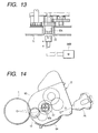
- the photosensitive drum 1 rotates in a direction indicated by an arrow (counterclockwise) in FIG. 1 dependently on image forming operations while receiving a driving force from a driving motor 24M (see FIG. 13).
- the charging means 2 uses the so-called contact charging method and functions to uniformly charge a surface of the photosensitive drum 1 by applying a voltage to an electrically conductive roller which rotates in contact with the surface of the photosensitive drum 1.
- the laser diode When an image signal is given to a laser diode (not shown) in the above described exposure means 3 which exposes the photosensitive drum 1 charged by the charging means 2, the laser diode irradiates a polygon mirror 3a with an image beam corresponding to the image signal.
- the polygon mirror 3a is rotated at a high speed by a scanner motor 3b and the image beam which is reflected by the above described polygon mirror 3a selectively exposes the surface of the photosensitive drum 1 by way of a reflecting mirror 3d rotating at a constant speed, thereby forming an electrostatic latent image on the photosensitive drum 1.
- the above described electrostatic latent image is developed color by color with the above described developing cartridges (developing apparatuses) D (Dm, Dc, Dy and Db).
- D developing apparatuses
- Dm, Dc, Dy and Db The configuration of the developing will be described later.
- the toner image which is developed with the developing cartridges D is transferred to the intermediate transferring unit 4 serving as a second image bearing body which performs secondary transferring of a plurality of toner images consecutively transferred primarily from the photosensitive drum 1 and overlapped collectively to the recording medium P and has an intermediate transferring belt 4a running in a direction indicated by an arrow R4.
- the above described intermediate transferring belt 4a has a circumferential length of approximately 440 mm and is stretched over a driving roller 4b, a secondary transferring opposed roller 4c and a follower roller 4d.
- the image forming apparatus has a clamp roller 4j which is located at a position where the clamp roller 4j is brought close to the follower roller 4d and presses the intermediate transferring belt 4a to the photosensitive drum 1, and another position where the clamp roller is retreated to allow the intermediate transferring belt 4a is apart from the photosensitive drum 1.
- the intermediate transferring belt 4a runs in the direction indicated by the arrow R4 as the driving roller 4b rotates and disposed at a predetermined location outside the above described intermediate transferring belt 4a is a cleaning unit 4e which can be brought into contact and separated into and from a surface of the above described intermediate transferring belt 4a so that the toner remaining after the collective secondary transferring of the toner images to the recording medium P is removed with the cleaning unit 4e.
- a cleaning method for the intermediate transferring belt 4a is not limited to the above described electrostatic cleaning and it is possible to adopt a mechanical method using a blade, a fur brush or the like, a method using a combination of the electrostatic cleaning and mechanical method, and the like.
- the cleaning means 9 which removes the toner remaining on the surface of the photosensitive drum 1 after the toner image is transferred to the intermediate transferring unit 4 scrapes off residual toner with the cleaning blade 9b which is brought into contact with the surface of the photosensitive drum 1 and accumulates the residual toner into a waste toner container 9c.
- This waste toner container 9c is composed of the cleaning frame body 9a, an amount of the waste toner stored in the waste toner container or a volume of the waste toner container 9c is set so that the container will not be completely filled with the waste toner before the service life of the photosensitive drum 1 expires and disposal of the waste toner in the waste toner container 9c can be performed together with exchange of the process cartridge U when the service life of the photosensitive drum 1 is expired.
- the above described transferring means 6 which transfers the toner images multiply transferred to the intermediate transferring unit 4 to the recording medium P is composed of a transferring roller in this embodiment, and the transferring roller 6 is composed by winding an expanded elastic material having medium resistance around a metal shaft and disposed movably in an up-down direction in FIG. 1.
- this transferring roller 6 is located downward and kept apart from the intermediate transferring unit 4 as indicated by a solid line in FIG. 1 so as not to disturb the images.
- the transferring roller 6 is moved by a cam (not shown) to an upward location as indicated by a chain line in FIG. 1 at a timing to transfer the color image to the recording medium P. Accordingly, the transferring roller 6 is pressed to the intermediate transferring unit 4 under a predetermined pressure by way of the recording medium P. Simultaneously, a bias voltage is applied to the transferring roller 6, whereby the toner images are transferred from the intermediate transferring unit 4 to the recording medium P.
- the above described conveying means 5 which conveys the above described recording medium P is composed of a sheet feeding cassette 5a containing a plurality of recording media P, a pickup roller 5b, a feeding roller 5c1, a double feeding preventing retard roller 5c2, a conveying roller pair 5d, a registration roller pair 5e, a discharge roller pair 5f and a conveyance guide 5g as shown in FIG. 1.
- the pickup roller 5b is rotatingly driven in correspondence to an image forming operation, thereby separating and feeding the recording media P in the sheet feeding cassette 5a one by one.
- the recording medium P sent out of the sheet feeding cassette 5a attains to the registration roller pair 5e by way of the conveying roller pair 5d while being guided by the conveyance guide 5g.
- the registration roller pair 5e performs a non-rotating operation for setting the recording medium P in a stationary standby condition and a rotating operation for conveying the recording medium P to the intermediate transferring unit 4 in a predetermined sequence during the image forming operation as well as positioning between the image and the recording medium P is performed at a next transferring step, and the color image is transferred to the recording medium P by the above described transferring means 6.
- the recording medium P to which the color image is transferred is conveyed to the fixing means 7 for fixing the toner image.
- the fixing means 7 is composed of a fixing roller 7a for applying heat to the recording medium P and a pressurizing roller 7b for bringing the recording medium P into pressure contact with the fixing roller 7a: both the rollers 7a and 7b being hollow rollers which comprise heaters and to be rotatingly driven respectively.
- the toner images are fixed to the recording medium P by conveying the recording medium P while applying heat and a pressure to the recording medium P and the recording medium P on which the toner is fixed is discharged into the discharge section 8 by a discharge roller pair 5f composing the conveying means 5.
- the image forming apparatus has four developing cartridges D (Dm, Dc, Dy and Db) which are capable of developing colors of magenta, cyan, yellow and black for forming a full-color image.
- the developing cartridges D are detachably attached to a rotary unit 11 rotating around a center shaft 10 as shown in FIGS. 1 through 3.
- the cartridges D are rotatingly moved around the center shaft 10 in a condition where the cartridges are held on the rotary unit 11 and a developing cartridge D containing a predetermined color toner is stopped at a position opposed to the photosensitive drum 1.
- the developing roller 12 functioning as the developer bearing body (see FIG. 4) is positioned so as to be opposed to the photosensitive drum 1 with a slight gap (on the order of approximately 300 ⁇ m) reserved and the toner is supplied in correspondence to the electrostatic latent image on the photosensitive drum 1, whereby the electrostatic latent image on the photosensitive drum 1 is developed.
- the rotary unit 11 rotates each time the intermediate transferring unit 4 makes a rotation to carry out a developing step in a sequence of a magenta developing cartridge Dm containing a magenta color toner, a cyan developing cartridge Dc containing a cyan color toner, a yellow developing cartridge Dy containing a yellow color toner and a black developing cartridge containing a black color toner.
- the black color toner is a magnetic toner, whereas the other color toners are non-magnetic toners.
- FIG. 4 shows a condition where the cartridge D (for example, the yellow developing cartridge Dy) is positioned and stationary at a developing position opposed to the photosensitive drum 1.
- This developing cartridge D (Dy) has a developing roller 12 functioning as a toner carrier which supplies the toner to the photosensitive drum 1, a toner accommodating section 63a which accommodates the toner to the above described developing roller 12, a cartridge frame 63 which is composed by coupling a plurality of frames for supporting the developing roller 12 and a shutter 64 which opens and closes an opening for exposing the developing roller 12.
- a toner feeding member 15 disposed in the above described toner accommodating section 63a is a toner feeding member 15.
- a toner seal 27 attached to a new developing cartridge D is a toner seal 27 to prevent the toner from leaking out of the above described toner accommodating section 63a.
- the toner can therefore be supplied from the toner accommodating section 63a to the developing roller 12 when a user unseals the toner accommodating section 63a by peeling off the above described toner seal 27 prior to mounting of the new developing cartridge D on the main body 30 of the image forming apparatus.
- the developing roller 12 is an aluminum roller which is rotatably supported and a developing blade 16 functioning as a developer regulating member is in pressure contact with a circumferential surface of the developing roller 12. Accordingly, the toner is coated as a thin layer on the circumferential surface and electric charges are imparted to the toner (frictional charge) when the developing roller 12 rotates in a direction indicated by an arrow (clockwise direction) in FIG. 4.
- a developing bias voltage supplied from the main body 30 of the image forming apparatus is applied to the developing roller 12 which is opposed to the photosensitive drum 1 on which the electrostatic image is formed, whereby a toner image is formed on the photosensitive drum 1 in correspondence to the electrostatic image.
- the magenta developing cartridge Dm, the cyan developing cartridge Dc, the yellow developing cartridge Dy and the black developing cartridge Db have the same configuration and the same function.
- the developing roller 12 of each developing cartridge D is connected to a color developing high voltage power supply and a driving source disposed in the main body 30 of the image forming apparatus when the developing cartridge D is moved to the developing position, and the developing bias voltage is applied and a driving force is transmitted consecutively and selectively to the developing cartridges D for rotating drive of the developing rollers 12 and the like.
- each developing cartridge D has a coating roller 19 which is rotatably disposed in the cartridge frame 63 and has a circumferential surface rotating in a direction reverse to a rotating direction of the circumferential surface of the developing roller 12.
- a black developing cartridge Db shown in FIG. 5 has a coating roller.
- the toner adheres to the developing roller 12 owing to a magnetic force of a magnet (not shown) built in the developing roller 12 and an adhesive force, and the developing blade 16 which is in contact with the circumferential surface of the developing roller 12 regulates a thickness of a toner layer and imparts triboelectric charges to the toner.
- FIGS. 6 and 7 are perspective views of the developing cartridge
- FIG. 8 is an exploded perspective view of the developing cartridge
- FIGS. 9 and 10 are side views of the developing cartridge in a condition where a shutter is closed
- FIGS. 11 and 12 are side views of the developing cartridge in a condition where the shutter is open.
- An opening 63b is formed in the cartridge frame 63 of the developing cartridge D in a longitudinal direction as shown in FIG. 8 and the developing roller 12 is supported by the cartridge frame 63 so as to be exposed from the opening 63b.
- a cylindrical protrusion 63c is formed integrally with the cartridge frame 63 nearly at a center of a side surface in the longitudinal direction of the cartridge frame 63. The protrusion 63c serves as a guide for inserting the developing cartridge D into the main body 30 of the image forming apparatus and a rotational center for attaching and detaching the developing cartridge D to and from the main body 30 of the image forming apparatus.
- a protrusion 63g is detachably attached nearly at a center of the other side surface 63i in the longitudinal direction of the cartridge frame 63.
- the protrusion 63g is shown in a detached condition in FIG. 8.
- the protrusion 63g is attached to the cartridge frame 63 by inserting an inserting portion 63g1 into a hole (not shown) formed in the side surface 63i.
- An inverted pawl like portion (not shown) is formed on a tip of the inserting portion 63g1 so that the protrusion 63g is attached to the cartridge frame 63 by the inverted pawl like portion which is engaged with the cartridge frame.
- the developing cartridge D When the developing cartridge D is mounted at a mounting position of the rotary unit 11, a tip surface 63g2 of the protrusion 63g is pushed by a pushing member (not shown) protruded by an elastic force from an inside wall surface of the rotary unit 11. Accordingly, the developing cartridge D is pushed toward the side surface 63h (in a direction indicated by an arrow Q in FIG. 8). The developing cartridge D is therefore attached to the rotary unit 11 (main unit 30 of the image forming apparatus) taking as standard the side surface 63h on which a driving force receiving member 22 is disposed.
- spacer rollers 12a and 12b which have a radius larger than that of the above described developing roller 12 by a distance corresponding to a developing gap. Accordingly, a predetermined gap is reserved between the developing roller 12 and the photosensitive drum 1 at the developing position by pressing the spacer rollers 12a and 12b to the circumferential surface of the photosensitive drum 1 with an urging force of urging means 25 (see FIG. 14) or a compression coil spring 10b (see FIGS. 2 and 3) which urges a slide member 10a.
- the above described developing blade 16 has an elastic blade 102 and is attached to the cartridge frame 63 by screwing a plurality of machine screws 16b to a blade metal plate 16a, a supporting member. A configuration of the developing blade 16 will be described in detail later.
- This lock member 71 has a lock engaging portion 71b which is to be engaged with a shutter engaging concave portion 64t formed in a side wall 64e of a shutter 64, a supporting portion 71a for supporting the above described lock engaging portion 71b, and attaching portions 71c and 71d which are to be engaged with holes 63j1 and 63j2 formed in the side surface 63h of the cartridge frame 63.
- the lock member 71 is a monolithically molded plastic member, an arm portion 71g of the above described lock member 71 comes into contact with a fixed portion disposed in the main body 30 of the image forming apparatus at a process to mount at the mounting position, the above described supporting portion 71a is deflected and the above described engaging portion 71b is disengaged from the shutter engaging concave portion 64t, thereby unlocking the shutter 64.
- a protrusion 63d which has a semispherical fitting portion is formed only on the side surface 63h in the longitudinal direction of the developing cartridge frame 63 as shown in FIGS. 3, 6 through 8, 10 and 12.
- a hole 64u is formed in the shutter 64 at a location corresponding to the protrusion 63d. Since the protrusion 64d is fitted in the hole 64u in the condition where the shutter 64 is closed, the developing cartridge frame 63 does not rotate to a position unstable relative to the shutter 64 even when the shutter 64 is unlocked by the lock member 71 as described above.
- a positioning bosses 63m (63m1 and 63m2) and spring bearings 63k (63k1 and 63k2) protrude from the side surface 63h and the other side surface 63i of the cartridge frame 63 as shown in FIGS. 9 and 10.
- reference numeral 73 in FIG. 9 denotes a toner seal pulling grip which is used for pulling out the above described toner seal 27.
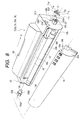
- the developing blade 16 consists of two layers as shown in FIG. 15. That is, the developing blade 16 consists of a supporting plate 101 and a elastic blade 102 from a side of a developing member supporting frame 63A.
- Positioning bearing surfaces 63A1 and 63A2 for mounting the developing blade 16 are disposed at both ends in the longitudinal direction of the developing member supporting frame 63A, and holes 63A3 for fixing the developing blade 16 to the developing member supporting frame 63A are formed in these bearing surfaces 63A1 and 63A2 respectively.
- a rectangular dowel 63A4 having a rectangular sectional shape is studded outside the hole 63A3 in the bearing surface 63A1 at the end in the longitudinal direction and a round dowel 63A6 is studded outside the hole 63A3 in the bearing surface 63A2 at the other end in the longitudinal direction.
- holes 101c and 102c for a machine screw 105 are formed so as to correspond to the hole 63A3 in the bearing surface 63A2 of the developing member supporting frame 63A, and holes 101d and 102d for a machine screw 106 are formed at the other ends respectively so as to correspond to the hole 63A3 in the bearing surface 63A1.
- round holes 102e and 102f for fitting the round dowels 101e and 101f are formed at the same locations respectively outside the above described holes 101c, 102c and 101d, 102d at both the ends of the supporting plate 101 and the elastic blade 102 of the developing blade 16.
- a hole 101g for fitting over the round dowel 63A6 formed on the bearing surface 63A2 of the developing member supporting frame 63A.
- a rectangular slot 101h for fitting over the rectangular dowel 63A4 which is disposed on the bearing surface 63A1 of the developing member supporting frame 63A.
- the developing blade 16 is attached to the developing member supporting frame 63A in the following sequence:
- the supporting plate 101 is a metal plate having a thickness on the order of 1 to 2 mm, and since rust produced on the supporting plate 101 causes improper development, the supporting plate 101 is made of stainless steel or plated with nickel or the like. Furthermore, the elastic blade 102 is thinner than the supporting plate and is made of an elastic thin metal plate such as stainless steel having a thickness of 0.1 mm or phosphor bronze.
- the embodiment in which the elastic blade 102 and the supporting plate 101 of the developing blade 16 are welded at least five or more portions having the nugget diameter of 0.5 to 2 mm is capable of preventing the developing blade 16 from being deformed in the longitudinal direction and uniformalizing a contact pressure of the above described developing blade 16 to the developing roller 12, thereby preventing an uneven image density from being produced and allowing high quality image to be obtained stably.
- the intervals between adjacent welded portions of 3 to 30 mm in particular is effective for uniformalization of the above described contact pressure.
- the above described YAG (Y 3 Al 5 O 12 : Nd 3+ ) laser exhibits an efficiency higher than other lasers and is preferably used.
Landscapes
- Physics & Mathematics (AREA)
- General Physics & Mathematics (AREA)
- Dry Development In Electrophotography (AREA)
- Electrophotography Configuration And Component (AREA)
Abstract
Description
Claims (12)
- A developing apparatus comprising:a developing frame having an opening;a developer carrying body disposed in said opening and carrying a developer; anda regulating member for regulating a thickness of the developer carried by said developer carrying body,wherein said regulating member has an elastic blade to be brought into contact with the developer and a supporting member for supporting said elastic blade, and said supporting member is supported by said developing frame, andwherein said elastic blade is coupled with said supporting member by welding.
- A developing apparatus according to claim 1, wherein said elastic blade is welded to said supporting member at a plurality of portions at intervals in a longitudinal direction of said elastic blade.
- A developing apparatus according to claim 2, wherein said intervals of said plurality of portions are 3 to 30 mm.
- A developing apparatus according to claim 2, wherein said plurality of portions are at least five or more.
- A developing apparatus according to any one of claims 1 through 4, wherein the portion at which said elastic blade is welded to said supporting member has a nugget diameter of 0.5 to 2 mm.
- A developing apparatus according to claim 1, wherein said elastic blade is coupled with said supporting member by YAG laser welding.
- A developing apparatus according to claim 1, wherein said elastic blade has a thickness smaller than that of said supporting member.
- A developing apparatus according to claim 7, wherein said elastic blade has a thickness of 1 to 2 mm.
- A developing apparatus according to claim 1, wherein said elastic blade has a metal plate.
- A developing apparatus according to claim 1, wherein said developing apparatus is detachably attachable to a main body of an image forming apparatus.
- A developing apparatus according to claim 1, wherein said developing apparatus is disposed together with an image bearing body in a process cartridge detachably attachable to an image forming apparatus.
- An assembling method for a developing apparatus comprising steps of:overlapping an elastic blade for regulating a thickness of a developer carried by a developer carrying body with a supporting member;coupling said elastic blade with said supporting member by welding; andattaching said supporting member to a developing frame.
Applications Claiming Priority (2)
| Application Number | Priority Date | Filing Date | Title |
|---|---|---|---|
| JP2000111585 | 2000-04-13 | ||
| JP2000111585 | 2000-04-13 |
Publications (2)
| Publication Number | Publication Date |
|---|---|
| EP1146400A2 true EP1146400A2 (en) | 2001-10-17 |
| EP1146400A3 EP1146400A3 (en) | 2005-08-03 |
Family
ID=18623891
Family Applications (1)
| Application Number | Title | Priority Date | Filing Date |
|---|---|---|---|
| EP01109146A Withdrawn EP1146400A3 (en) | 2000-04-13 | 2001-04-12 | Developing apparatus and assembling method for the same |
Country Status (2)
| Country | Link |
|---|---|
| US (1) | US6535709B2 (en) |
| EP (1) | EP1146400A3 (en) |
Families Citing this family (18)
| Publication number | Priority date | Publication date | Assignee | Title |
|---|---|---|---|---|
| JP2003228234A (en) * | 2002-02-01 | 2003-08-15 | Canon Inc | Process cartridge and image forming apparatus |
| US7236729B2 (en) * | 2004-07-27 | 2007-06-26 | Lexmark International, Inc. | Electrophotographic toner regulating member with induced strain outside elastic response region |
| US7336913B2 (en) * | 2004-07-29 | 2008-02-26 | Brother Kogyo Kabushiki Kaisha | Developing apparatus, process cartridge and image forming apparatus for preventing leakage |
| KR20080023987A (en) * | 2006-09-12 | 2008-03-17 | 삼성전자주식회사 | Developer layer regulating apparatus of image forming apparatus, developing apparatus employing the same, image forming apparatus and developer layer regulating method |
| JP5521659B2 (en) | 2009-12-25 | 2014-06-18 | ブラザー工業株式会社 | Development device |
| JP5418314B2 (en) | 2009-12-25 | 2014-02-19 | ブラザー工業株式会社 | Developing device and image forming apparatus |
| JP5521539B2 (en) * | 2009-12-25 | 2014-06-18 | ブラザー工業株式会社 | Development device |
| JP2011242757A (en) | 2010-04-20 | 2011-12-01 | Canon Inc | Regulating member, cleaning member, developing device, cleaning device, process cartridge, and image forming apparatus |
| US8687984B2 (en) | 2010-10-15 | 2014-04-01 | Canon Kabushiki Kaisha | Image forming apparatus |
| JP2013029733A (en) * | 2011-07-29 | 2013-02-07 | Canon Inc | Cover member and cartridge |
| JP6312407B2 (en) | 2012-12-12 | 2018-04-18 | キヤノン株式会社 | Image forming apparatus and cartridge |
| US9377711B2 (en) | 2013-09-30 | 2016-06-28 | Brother Kogyo Kabushiki Kaisha | Developing device, blade unit, and developing device manufacturing method |
| JP2015069165A (en) * | 2013-09-30 | 2015-04-13 | ブラザー工業株式会社 | Developing device, blade unit, and method of manufacturing developing device |
| JP2015069166A (en) | 2013-09-30 | 2015-04-13 | ブラザー工業株式会社 | Developing device, blade unit, and manufacturing method of developing device |
| JP6268884B2 (en) * | 2013-09-30 | 2018-01-31 | ブラザー工業株式会社 | Developing device, blade unit, and manufacturing method of developing device |
| JP6221906B2 (en) | 2014-03-31 | 2017-11-01 | ブラザー工業株式会社 | Developing device and manufacturing method of developing device |
| JP6582972B2 (en) | 2015-12-25 | 2019-10-02 | ブラザー工業株式会社 | Developer cartridge |
| JP7451175B2 (en) * | 2019-12-27 | 2024-03-18 | キヤノン株式会社 | developing device |
Family Cites Families (9)
| Publication number | Priority date | Publication date | Assignee | Title |
|---|---|---|---|---|
| JPS6122372A (en) * | 1984-07-10 | 1986-01-30 | Toshiba Corp | Developing device |
| JPS62270988A (en) * | 1986-05-20 | 1987-11-25 | Olympus Optical Co Ltd | Blade cleaning device |
| JPH09101676A (en) * | 1995-10-06 | 1997-04-15 | Casio Electron Mfg Co Ltd | Developing device and multicolor image forming apparatus using the same |
| JPH1173010A (en) | 1997-07-03 | 1999-03-16 | Canon Inc | Developing cartridge and electrophotographic image forming apparatus |
| JP3679614B2 (en) | 1997-07-03 | 2005-08-03 | キヤノン株式会社 | Shutter, developing cartridge, and electrophotographic image forming apparatus |
| JP3832972B2 (en) | 1997-07-03 | 2006-10-11 | キヤノン株式会社 | Developer cartridge |
| JPH11149211A (en) | 1997-11-17 | 1999-06-02 | Canon Inc | Developing cartridge and electrophotographic image forming apparatus |
| JP3316437B2 (en) * | 1997-12-05 | 2002-08-19 | シャープ株式会社 | One-component toner developing device |
| JP2000137381A (en) * | 1998-08-26 | 2000-05-16 | Canon Inc | Blade member, method of manufacturing blade member, developing unit, and image forming apparatus |
-
2001
- 2001-04-09 US US09/828,145 patent/US6535709B2/en not_active Expired - Lifetime
- 2001-04-12 EP EP01109146A patent/EP1146400A3/en not_active Withdrawn
Also Published As
| Publication number | Publication date |
|---|---|
| EP1146400A3 (en) | 2005-08-03 |
| US20010031158A1 (en) | 2001-10-18 |
| US6535709B2 (en) | 2003-03-18 |
Similar Documents
| Publication | Publication Date | Title |
|---|---|---|
| US6535709B2 (en) | Developing apparatus featuring an end of a regulating member coupled to a supporting member of the apparatus, regulating member, and method for assembling the same | |
| US7158735B2 (en) | Process cartridge, mounting method of electrophotographic photosensitive drum and replacing method of the photosensitive drum | |
| US6735403B2 (en) | Image forming apparatus to which a developing cartridge or process cartridge are detachably mountable comprising driving control means for permitting and preventing transmission of a driving force to a winding member | |
| US7127194B2 (en) | Process cartridge, positioning mechanism therefor and electrophotographic image forming apparatus | |
| EP0840178B1 (en) | Developing cartridge and electrophotographic image forming apparatus | |
| JP3630957B2 (en) | Development device | |
| JP3684195B2 (en) | Process cartridge and electrophotographic image forming apparatus | |
| US6181897B1 (en) | Developing apparatus | |
| US20020003974A1 (en) | Developing device with a devolper thickness control feature and method for using the same | |
| JP2003195725A (en) | Process cartridge and electrophotographic image forming apparatus | |
| US6654583B2 (en) | Developing apparatus | |
| JP2001356592A (en) | Developing device and assembling method thereof | |
| JP2003241618A (en) | Image forming device | |
| JP2005043537A (en) | Process cartridge and image forming apparatus using the same | |
| JP2005121763A (en) | Developing device and developing device assembling method | |
| JP2004085648A (en) | Developing device, process cartridge and image forming device | |
| JP2005043539A (en) | Cleaning device and process cartridge | |
| JP2005099231A (en) | Process cartridge and electrophotographic image forming apparatus | |
| JP2003195614A (en) | Color developing cartridge and color electrophotographic image forming apparatus | |
| JP2004085901A (en) | Developer amount detecting device, developing device, and electrophotographic image forming device | |
| JP2007025345A (en) | Development device, process cartridge, image forming device | |
| JP2004333929A (en) | Image forming device | |
| JP3977361B2 (en) | Process cartridge and electrophotographic image forming apparatus | |
| JP2004037913A (en) | Developing device, developing cartridge, process cartridge, and image forming apparatus | |
| JP2004037637A (en) | Cleaning device, process cartridge, and image forming device |
Legal Events
| Date | Code | Title | Description |
|---|---|---|---|
| PUAI | Public reference made under article 153(3) epc to a published international application that has entered the european phase |
Free format text: ORIGINAL CODE: 0009012 |
|
| AK | Designated contracting states |
Kind code of ref document: A2 Designated state(s): AT BE CH CY DE DK ES FI FR GB GR IE IT LI LU MC NL PT SE TR |
|
| AX | Request for extension of the european patent |
Free format text: AL;LT;LV;MK;RO;SI |
|
| PUAL | Search report despatched |
Free format text: ORIGINAL CODE: 0009013 |
|
| AK | Designated contracting states |
Kind code of ref document: A3 Designated state(s): AT BE CH CY DE DK ES FI FR GB GR IE IT LI LU MC NL PT SE TR |
|
| AX | Request for extension of the european patent |
Extension state: AL LT LV MK RO SI |
|
| 17P | Request for examination filed |
Effective date: 20060203 |
|
| AKX | Designation fees paid |
Designated state(s): DE FR GB IT |
|
| 17Q | First examination report despatched |
Effective date: 20061102 |
|
| STAA | Information on the status of an ep patent application or granted ep patent |
Free format text: STATUS: THE APPLICATION HAS BEEN WITHDRAWN |
|
| 18W | Application withdrawn |
Effective date: 20070305 |