EP1146359A2 - Fiberoptic polarizer and method of making the same - Google Patents
Fiberoptic polarizer and method of making the same Download PDFInfo
- Publication number
- EP1146359A2 EP1146359A2 EP00128594A EP00128594A EP1146359A2 EP 1146359 A2 EP1146359 A2 EP 1146359A2 EP 00128594 A EP00128594 A EP 00128594A EP 00128594 A EP00128594 A EP 00128594A EP 1146359 A2 EP1146359 A2 EP 1146359A2
- Authority
- EP
- European Patent Office
- Prior art keywords
- fiber
- polarizing
- glass
- polarizing material
- core
- Prior art date
- Legal status (The legal status is an assumption and is not a legal conclusion. Google has not performed a legal analysis and makes no representation as to the accuracy of the status listed.)
- Withdrawn
Links
- 238000004519 manufacturing process Methods 0.000 title abstract description 17
- 239000000835 fiber Substances 0.000 claims abstract description 140
- 239000000463 material Substances 0.000 claims abstract description 82
- 238000000034 method Methods 0.000 claims abstract description 50
- 230000003287 optical effect Effects 0.000 claims abstract description 41
- 239000000758 substrate Substances 0.000 claims abstract description 31
- 239000000203 mixture Substances 0.000 claims abstract description 20
- 230000008878 coupling Effects 0.000 claims abstract description 15
- 238000010168 coupling process Methods 0.000 claims abstract description 15
- 238000005859 coupling reaction Methods 0.000 claims abstract description 15
- 239000011521 glass Substances 0.000 claims description 66
- 229910052709 silver Inorganic materials 0.000 claims description 23
- VYPSYNLAJGMNEJ-UHFFFAOYSA-N Silicium dioxide Chemical compound O=[Si]=O VYPSYNLAJGMNEJ-UHFFFAOYSA-N 0.000 claims description 21
- 239000002245 particle Substances 0.000 claims description 21
- 239000004332 silver Substances 0.000 claims description 20
- 239000013307 optical fiber Substances 0.000 claims description 18
- BQCADISMDOOEFD-UHFFFAOYSA-N Silver Chemical compound [Ag] BQCADISMDOOEFD-UHFFFAOYSA-N 0.000 claims description 17
- PNEYBMLMFCGWSK-UHFFFAOYSA-N aluminium oxide Inorganic materials [O-2].[O-2].[O-2].[Al+3].[Al+3] PNEYBMLMFCGWSK-UHFFFAOYSA-N 0.000 claims description 12
- 229910052593 corundum Inorganic materials 0.000 claims description 12
- 229910052736 halogen Inorganic materials 0.000 claims description 12
- 150000002367 halogens Chemical class 0.000 claims description 12
- 229910001845 yogo sapphire Inorganic materials 0.000 claims description 12
- 229910052681 coesite Inorganic materials 0.000 claims description 10
- 229910052906 cristobalite Inorganic materials 0.000 claims description 10
- 239000000377 silicon dioxide Substances 0.000 claims description 10
- 229910052682 stishovite Inorganic materials 0.000 claims description 10
- 229910052905 tridymite Inorganic materials 0.000 claims description 10
- KOPBYBDAPCDYFK-UHFFFAOYSA-N Cs2O Inorganic materials [O-2].[Cs+].[Cs+] KOPBYBDAPCDYFK-UHFFFAOYSA-N 0.000 claims description 9
- FUJCRWPEOMXPAD-UHFFFAOYSA-N Li2O Inorganic materials [Li+].[Li+].[O-2] FUJCRWPEOMXPAD-UHFFFAOYSA-N 0.000 claims description 9
- KKCBUQHMOMHUOY-UHFFFAOYSA-N Na2O Inorganic materials [O-2].[Na+].[Na+] KKCBUQHMOMHUOY-UHFFFAOYSA-N 0.000 claims description 9
- 239000000853 adhesive Substances 0.000 claims description 9
- 230000001070 adhesive effect Effects 0.000 claims description 9
- 229910000272 alkali metal oxide Inorganic materials 0.000 claims description 9
- AKUNKIJLSDQFLS-UHFFFAOYSA-M dicesium;hydroxide Chemical compound [OH-].[Cs+].[Cs+] AKUNKIJLSDQFLS-UHFFFAOYSA-M 0.000 claims description 9
- XUCJHNOBJLKZNU-UHFFFAOYSA-M dilithium;hydroxide Chemical compound [Li+].[Li+].[OH-] XUCJHNOBJLKZNU-UHFFFAOYSA-M 0.000 claims description 9
- 229910001507 metal halide Inorganic materials 0.000 claims description 8
- 150000005309 metal halides Chemical class 0.000 claims description 8
- 229910052794 bromium Inorganic materials 0.000 claims description 6
- 229910052801 chlorine Inorganic materials 0.000 claims description 6
- 229910052740 iodine Inorganic materials 0.000 claims description 6
- 239000002923 metal particle Substances 0.000 claims description 5
- 239000002585 base Substances 0.000 claims description 3
- 239000006121 base glass Substances 0.000 claims description 3
- 239000003795 chemical substances by application Substances 0.000 claims description 3
- 230000001747 exhibiting effect Effects 0.000 claims description 3
- 229910044991 metal oxide Inorganic materials 0.000 claims description 3
- 150000004706 metal oxides Chemical class 0.000 claims description 3
- 229910001953 rubidium(I) oxide Inorganic materials 0.000 claims description 3
- -1 silver halide Chemical class 0.000 claims description 3
- 238000002834 transmittance Methods 0.000 claims 4
- 239000013528 metallic particle Substances 0.000 claims 3
- 230000008033 biological extinction Effects 0.000 claims 2
- 238000003780 insertion Methods 0.000 description 7
- 230000037431 insertion Effects 0.000 description 7
- 239000010410 layer Substances 0.000 description 7
- 239000004593 Epoxy Substances 0.000 description 4
- 238000013461 design Methods 0.000 description 4
- 239000005318 dichroic glass Substances 0.000 description 4
- 239000004575 stone Substances 0.000 description 4
- 238000005516 engineering process Methods 0.000 description 3
- 230000010354 integration Effects 0.000 description 3
- 235000012431 wafers Nutrition 0.000 description 3
- 238000005520 cutting process Methods 0.000 description 2
- 239000005350 fused silica glass Substances 0.000 description 2
- 239000003292 glue Substances 0.000 description 2
- 238000010438 heat treatment Methods 0.000 description 2
- 229910052751 metal Inorganic materials 0.000 description 2
- 239000002184 metal Substances 0.000 description 2
- 238000012986 modification Methods 0.000 description 2
- 230000004048 modification Effects 0.000 description 2
- 238000013459 approach Methods 0.000 description 1
- 238000000149 argon plasma sintering Methods 0.000 description 1
- 239000012298 atmosphere Substances 0.000 description 1
- 230000005540 biological transmission Effects 0.000 description 1
- 238000004364 calculation method Methods 0.000 description 1
- 239000004568 cement Substances 0.000 description 1
- 239000011248 coating agent Substances 0.000 description 1
- 238000000576 coating method Methods 0.000 description 1
- 238000004891 communication Methods 0.000 description 1
- 239000006059 cover glass Substances 0.000 description 1
- 239000013078 crystal Substances 0.000 description 1
- 230000002939 deleterious effect Effects 0.000 description 1
- 230000001419 dependent effect Effects 0.000 description 1
- 238000000151 deposition Methods 0.000 description 1
- 238000009792 diffusion process Methods 0.000 description 1
- 230000000694 effects Effects 0.000 description 1
- 150000004820 halides Chemical class 0.000 description 1
- 230000005693 optoelectronics Effects 0.000 description 1
- 238000004806 packaging method and process Methods 0.000 description 1
- 238000012856 packing Methods 0.000 description 1
- 238000001552 radio frequency sputter deposition Methods 0.000 description 1
- 238000000926 separation method Methods 0.000 description 1
- 235000012239 silicon dioxide Nutrition 0.000 description 1
- 239000002356 single layer Substances 0.000 description 1
Images


Classifications
-
- G—PHYSICS
- G02—OPTICS
- G02B—OPTICAL ELEMENTS, SYSTEMS OR APPARATUS
- G02B6/00—Light guides; Structural details of arrangements comprising light guides and other optical elements, e.g. couplings
- G02B6/10—Light guides; Structural details of arrangements comprising light guides and other optical elements, e.g. couplings of the optical waveguide type
- G02B6/12—Light guides; Structural details of arrangements comprising light guides and other optical elements, e.g. couplings of the optical waveguide type of the integrated circuit kind
- G02B6/126—Light guides; Structural details of arrangements comprising light guides and other optical elements, e.g. couplings of the optical waveguide type of the integrated circuit kind using polarisation effects
-
- G—PHYSICS
- G02—OPTICS
- G02B—OPTICAL ELEMENTS, SYSTEMS OR APPARATUS
- G02B6/00—Light guides; Structural details of arrangements comprising light guides and other optical elements, e.g. couplings
- G02B6/10—Light guides; Structural details of arrangements comprising light guides and other optical elements, e.g. couplings of the optical waveguide type
- G02B6/12—Light guides; Structural details of arrangements comprising light guides and other optical elements, e.g. couplings of the optical waveguide type of the integrated circuit kind
- G02B6/12007—Light guides; Structural details of arrangements comprising light guides and other optical elements, e.g. couplings of the optical waveguide type of the integrated circuit kind forming wavelength selective elements, e.g. multiplexer, demultiplexer
-
- G—PHYSICS
- G02—OPTICS
- G02B—OPTICAL ELEMENTS, SYSTEMS OR APPARATUS
- G02B6/00—Light guides; Structural details of arrangements comprising light guides and other optical elements, e.g. couplings
- G02B6/24—Coupling light guides
- G02B6/26—Optical coupling means
- G02B6/27—Optical coupling means with polarisation selective and adjusting means
- G02B6/2726—Optical coupling means with polarisation selective and adjusting means in or on light guides, e.g. polarisation means assembled in a light guide
-
- G—PHYSICS
- G02—OPTICS
- G02B—OPTICAL ELEMENTS, SYSTEMS OR APPARATUS
- G02B6/00—Light guides; Structural details of arrangements comprising light guides and other optical elements, e.g. couplings
- G02B6/24—Coupling light guides
- G02B6/26—Optical coupling means
- G02B6/27—Optical coupling means with polarisation selective and adjusting means
- G02B6/2753—Optical coupling means with polarisation selective and adjusting means characterised by their function or use, i.e. of the complete device
- G02B6/2766—Manipulating the plane of polarisation from one input polarisation to another output polarisation, e.g. polarisation rotators, linear to circular polarisation converters
Definitions
- the invention relates to optical functional devices that are integrated directly into optical fibers for use in telecommunication systems. More particularly, the invention relates to a fiber-optic polarizer device and a method of making the device.
- optical functional devices such as isolators, switches, filters, and amplifiers must be inserted between optical fibers.
- Most in-line optical devices use lens elements to collimate a light beam from an incoming single-mode fiber (SMF) and focus it on an out-going SMF, where functional elements are placed in between two fibers.
- SMF single-mode fiber
- functional elements are placed in between two fibers.
- precise alignment within 0.1-0.5 ⁇ m
- Coupling loss between two optical fibers mainly depends on optical distance between the two fiber-ends, and the core diameter of each fiber.
- one of the goals is to shorten the optical path-length in order to decrease coupling loss caused by diffraction.
- Shiraishi's article discusses an approach that focuses on making fiber-integrated isolators, where the optical components are relatively thick, having several hundred microns. Therefore, employment of a fiber having a large core diameter, such as a TEC (Thermally Expanded Core)-fiber, is essential to suppress coupling loss in such a device.
- TEC Thermal Expanded Core
- a first type consists of a thick (> 0.1 mm thick) polarizer material that is placed in between a fiber collimator system.
- this first type of polarizer many optical components that require high structural preciseness are used in the polarizer, so that the cost is increased.
- one of the lenses collimates a light beam from an incoming fiber to the polarizer and the other lens focuses the light on an outgoing fiber. Because of the rather bulky arrangement and large thickness of the optical elements, such a polarizer design can not avoid large coupling losses between the two fibers without the use of a fiber collimator system that contains lenses.
- LAMIPOL laminated-type of polarizer material, known commercially as LAMIPOL by Sumitomo Osaka Cement (SOC).
- SOC Sumitomo Osaka Cement
- LAMIPOL is placed in between the end facets of two optical fibers.
- LAMIPOL has a structure where metal and dielectric layers are alternately laminated with periodicity, and is made by alternatively depositing Al (or Ge) and SiO 2 films with RF sputtering.
- LAMIPOL also has a thickness of typically about 30 ⁇ m. Due to the employment of such a thin polarizer, it was not necessary to use lens elements since the coupling loss is negligibly small.
- LAMIPOL in lens-free devices, however, has several problems.
- One of the major concerns is difficulty in handling for alignment during the fabrication process.
- LAMIPOL has a very small optical aperture (0.1mm x 1mm square or 0.1mm x 4.6mm square). This optical aperture is located at an end of a lateral side of a piece of LAMIPOL. Therefore, vertical alignment is essential for LAMIPOL to be inserted into a gap.
- LAMIPOL has a structure where metal and dielectric layers are alternately laminated with periodicity. Since the absorbing cross-section of a laminated structure depends strongly on the incident angle, another problem with Lamipol is its inherently small acceptance angle.
- the width of a gap needs to have a relatively tight tolerance for insertion of the LAMIPOL.
- LAMIPOL can be accidentally tilted into an incorrect angle relative to the normal of waveguide orientation. This tilting has a significant effect upon return and insertion losses.
- arranging optical components at a tilted angle against the normal of the optical axis in fiber-optic applications has been an effective configuration to improve return loss. But, because the acceptance angle of LAMIPOL is inherently small, a tilted configuration results in an increase in insertion loss.
- a fiber-optic polarizer device made by a process comprised of providing a substrate, coupling or embedding an optical fiber to the substrate, making a narrow trench across the fiber and fiber core at an angle, thereby bifurcating the fiber and its core into a first fiber core end and a second fiber core end, inserting and securing a thin polarizing material of a non-laminated structure, such as a dichroic glass polarizer, into the narrow trench, such that a light spot size emitted from a first fiber core is completely encompassed by the polarizing material, and the light spot size emerging from the polarizing material is substantially collected within or equal to the mode field diameter of a second fiber core.
- a non-laminated structure such as a dichroic glass polarizer
- the process is also an alignment-free process that enables easier and faster mass-fabrication.
- This process produces multiple polarizers at a time.
- the inventive polarizer exhibits a high degree of reliability in terms of mechanical strength and durability to weathering, since the polarizer is fabricated on a substrate in which the optical path is entirely sealed.
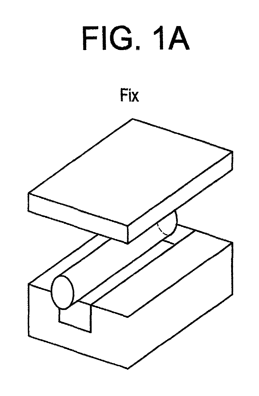
- FIGURE 1A shows an embodiment of the fabrication process for a fiber-optic polarizer using a thin polarizing material, where an array of optical fibers is coupled or embedded in a substrate.
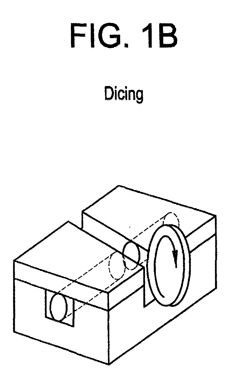
- FIGURE 1B shows an embodiment of the fabrication process for a fiber-optic polarizer using a thin polarizing material, where an array is cut at an angle to the optical axis of the fibers, to form a narrow trench.
- FIGURE 1C shows an embodiment of the fabrication process for a fiber-optic polarizer using a thin polarizing material, where a thin polarizing is inserted into the narrow trench made by the cut shown in Figure 1B.
- FIGURE 2 shows an embodiment of the fabrication process for a fiber-optic polarizer using a thin polarizing material.
- FIGURE 3 shows a detailed section of a microscopic photograph of the fiber optic polarizer shown in either Figures 1A-1C, or Figure 2.
- FIGURE 4 is a graphic plot that shows the relationship between optical loss versus distance between the end facets of two fibers, for three sets of fibers having varying diameters.
- FIGURE 5 shows an alternate embodiment of a fiber-optic polarizer having V-grooves, using a thin polarizing material.
- Our invention encompasses in one aspect a fiber-optic polarizer that comprises at least one optical fiber embedded in a substrate.
- the fiber and its fiber core is transversely bifurcated by a narrow trench into a first fiber portion having a first fiber core and a second fiber portion having a second fiber core, and a thin polarizing material positioned in the narrow trench.
- a light spot size emission from a first fiber core is encompassed by the polarizing material, and a light spot size emerging from the polarizing material is substantially incident upon a second fiber core.
- the each fiber core is substantially constant or equivalent in diameter and the polarizing material is not of a laminated structure, but rather is preferably "monolithic” or exhibits “dichroism.”
- the invention relates to a method for making such a fiber-optic polarizer. The method comprises providing a substrate, coupling an optical fiber to the substrate, making a narrow trench across the fiber at an angle, thereby, bifurcating the fiber and its core into a first fiber end and fiber core, and a second fiber end and fiber core. Then inserting and securing a thin, "monolithic” or “dichroic” polarizing material of a non-laminated structure into the narrow trench.
- the placement of the polarizing material is as such that a light spot size emitted from a first fiber core is mostly or completely encompassed by the polarizing material, and the light spot size emerging from the polarizing material is substantially collected within the mode field diameter of a second fiber core.
- the proposed polarizer device is realized by inserting a thin polarizing material into a narrow trench or gap in a waveguide at an angle in the range of about 0-10 degrees relative to the perpendicular of the fiber. More preferably, the angle ranges from about 3 or 4-8 or 9 degrees.
- Figure 1A-1C shows an embodiment of the fabrication process for the fiber-optic polarizer using a thin polarizing material.
- a fiber or an array of fibers is prepared.
- Figure 1A illustrates an array of optical fibers embedded in a substrate. The array is then cut.
- Figure 2A depicts the dicing of the assembled fibers across their optical axis at a predetermined angle by a blade, thus forming a narrow trench.
- a thin polarizing material is then inserted.
- Figure 1C displays a thin polarizing material inserted into the narrow trench, and affixed by refractive index matching optical adhesive. This is an essentially alignment free process.
- the polarizing material is affixed to the substrate having at least one optical fiber embedded within. This is accomplished, for example, with an index matching ultra-violet (UV) curable optical adhesive, such as #9389 by NTT-AT.
- UV ultra-violet
- the adhesive should have a refractive index that matches to that of the fiber core.
- Other media or adhesive such as an index-matching oil or epoxy could also be employed.
- the index-matching adhesive also ensures that the end facet of the fiber core is not exposed to air. It is desirable that the fiber is embedded and the waveguide not be exposed to air. This would reduce light attenuation and make it unnecessary to package the inventive polarizer device in expensive packing to protect the device from the deleterious effects of the atmosphere.
- the inventive polarizer has high mechanical strength, since the polarizer is made on a substrate. Moreover, the number of optical components needed to fabricate the polarizer device is very low.
- the components comprise a substrate, a cover glass, a thin polarizer, and an optical fiber.
- Multiple fiberoptic polarizers, such as used in an arrayed can be fabricated at a time with an alignment free process. Of course, a single fiberoptic polarizer can be made in an array process with subsequent separation of individual polarizer units.
- the thin polarizing material is a glass exhibiting dichroic ratios of up to 40 or greater and containing silver halide particles aligned along a common axis, the glass is characterized as being either phase separable or photochromic.
- the glass has a base composition, in weight percent, consisting essentially of: 1-15% Al 2 O 3 , 20-35% B 2 O 3 , 5-12% alkali metal oxide, and the remainder SiO 2 , with the proviso that where Al 2 O 3 is present in amounts greater than about 5%, at least 1% of a phase separating agent will be included in the composition.
- the glass when a photochromic glass is employed, the glass has a composition, in weight percent on an oxide basis, consisting essentially of: 4-26% Al 2 O 3 , 4-26% B 2 O 3 , 40-76% SiO2, and at least one alkali metal oxide selected from the group of 2-8% Li 2 O, 4-15% Na 2 O, 6-20% K 2 O, 8-25% Rb 2 O, and 10-30% Cs 2 O; at least one halogen in a minimum effective proportion of 0.2% Cl, 0.1% Br, and 0.08% I, and a minimum of silver in a proportion of 0.2%, where the effective halogen is Cl, 0.05% where the effective halogen is Br; but the glass contains at least 0.08% I, the sum of the base glass components, halogen, and silver constitute at least 85% by weight of the composition.
- a composition in weight percent on an oxide basis, consisting essentially of: 4-26% Al 2 O 3 , 4-26% B 2 O 3 , 40-76% SiO2, and at least one al
- Another type of a photochromic glass can have a composition, in weight percent on an oxide basis, consisting essentially of: 5-25% Al 2 O 3 , 14-23% B 2 O 3 , 20-65% SiO 2 , 0-25% P 2 O 5 , 0-2.5% Li 2 O, 0-9% Na 2 O, 0-17% K 2 O, 0-6% Cs 2 O, 8-20% Li 2 O+Na 2 O+K 2 O+Cs 2 O, 0.004-0.02% CuO, 0.15-0.3% Ag, 0.1-0.25% Cl, and 0.1-0.2% Br, the molar ratio of alkali metal oxide:B 2 O 3 ranges between about 0.55-.085, where the composition is essentially free from divalent metal oxides other than CuO, and the weight ratio of Ag:(Cl+Br) ranges from about 0.65-0.95.
- polarizing material that could work quite well in our present invention is the very thin glass articles such as that described in published Patent Application WO99/59006, which is herein incorporated by reference.
- WO99/59006 relates in part a method for making silver-containing glass and ultra-thin polarizing glass articles made from such glass.
- the polarizing glass is of a uniform polarizing consistency, as opposed to a laminated structure. That is, the glass should be monolithic, in that it has dispersed within, across its entire breadth and thickness, elongated submicroscopic metal particles. In this respect, the polarizing material should be of a non-laminated structure.
- the metal particles have a long axis such that the glass preferentially absorbs polarizing components of light that are parallel to the long axis. Hence, it permits high transmission of light, which vibrates perpendicular to the long axis. Further, the polarizing glass is essentially free of metal halide particles, which tend to impart certain undesired optical properties to the glass, such as light scattering caused by the presence of tiny halide crystals embedded in the glass, or unwanted photochromism.
- the polarizing material can and should be a single layer light polarizing device free of adjacent non-polarizing regions.
- a glass commercially known as Ultra-ThinTM Polarcor by Corning could be used. This type of glass, as disclosed in WO99/59006, is made according to a method comprising a number of steps. First, we obtain a polarizing glass comprising a first polarizing layer and a non-polarizing region, wherein the polarizing layer contains elongated metal particles and the non-polarizing region contains metal halide particles. Second, we bond the first polarizing layer of said polarizing glass to a substrate.
- the polarizing glass is cut into wafers, each having predetermined dimensions of length and width with a thickness of 10-50 ⁇ m (wafers can range in thickness from 10-15-25-30-35-40 ⁇ m). Additionally, each wafer has a large optical aperture and good thermal durability. Apertures as large as 10 mm x 10 mm square can be realized. 1 This type of polarizing material has a contrast ratio greater than 40 dB at 1.54 ⁇ m wavelength.
- the narrow trench of the present invention has a width of less than or equal to 70-60-50 ⁇ m. More preferably the trench has a width of about 10-20-30-50 ⁇ m.
- Figure 4 shows this dependent relationship for calculated coupling losses and the distance of a gap in which a piece of glass polarizer, such as Ultra-ThinTM, is sandwiched between two optical fibers having different mode field (10, 20, and 30 ⁇ m) diameters. As can be seen, coupling loss significantly increases with increasing distance.
- the optical fibers employed in the inventive polarizer device need not undergo specialized treatment, such as heating, to expand the diameter of their cores.
- Heat treatment for a thermally expanded core fundamentally requires precious temperature control as high as 1400°C for example without a damage of fiber, which result in high fabrication cost.
- Our inventive device and process do not require the use of TEC-fiber, because the thickness of the polarizing material used is very small, so as the coupling loss is negligible.
- any ordinary single mode optical fiber that has a core that is substantially constant in diameter can be used without fear of substantial diffusion or loss of light.
- substantially constant we mean an optical fiber that has a core diameter that is within normal manufacturing tolerances, which are well known.
- the diameter of a fiber core does not have a significantly tapered section, and does not vary by more than 50%, or by more than 10-15-25%.
- the core diameter of ordinary single mode fiber is approximately 10 ⁇ m.
- FIG. 2 shows one embodiment of the inventive fiber-optic polarizer.
- the fibers are embedded in a substrate with a narrow trench and diced at an angle ( ⁇ ) between 0-10 degrees (preferably 3° to 9°) relative to the normal of the optical axis of each fiber.
- the substrate can be made from a silica glass.
- Return loss, or back reflection, is virtually eliminated by the thin polarizing material inserted at a tilted angle. Necessary for optical performance, the inserted polarizing material should be insensitive to angle shift of the incident angle.
- a monolithic-type, dichroic glass polarizer such as Ultra ThinTM by Coming Inc., would satisfy this condition since its performance is insensitive to off-normal angle shift of incident angle.
- the return loss of the inventive fiberoptic polarizer in which UltraThinTM was inserted was measured to be 38-40-42-50dB, where tilting angles was in the range of 0 to 8 degrees. Insertion loss of those polarizers was measured to be 0.2-0.5dB.
- an optical loss caused by Frensnel reflection is negligibly small because of the small difference in refractive index between the core of an ordinary SMF and the polarizing material.
- antireflection coating on the polarizing material because of the negligibly small loss, since the angled bisection of the optical fiber effectively eliminates return loss.
- the contrast ratio was measured at a wavelength of interest (1,550 nm).
- the contrast ratio of a fiber optic polarizer using UltraThinTM was measured to range from about 33-48 dB, where the polarizer material is tilted at an angle from 0 to 8 degrees. Insertion loss for this material was measured to be less than 0.06 dB.
- a fiber-optic polarizer device is made of a single fiber coupled in a substrate with a V-groove.
- a polarizer made according to the fabrication scheme is illustrated in Figure 5.
- a V-groove is formed in planar piece of fused silica glass substrate, of approximately 0.6 mm thick by means of a precision dicing machine with V-groove blade. The angle of the cut is 90° and depth of the groove is 151 ⁇ m, respectively.
- a V-groove can be made with a 60° cut angle and 187 ⁇ m depth. Then, once prepared, a bare single mode fiber is laid in the groove with thermally curable epoxy.
- a 0.12mm thick glass cover is placed on the top of fused silica glass in order to settle the fiber in the groove. Then, this glass cover is adhered to the glass substrate, with the same epoxy. Subsequently, the epoxy is hardened on a hot plate.
- a trench is made with a two-step cutting using a 30 ⁇ m width blade. Alternatively, we can also use a one step cutting using a 30 ⁇ m width blade. To eliminate return loss, the angle of the trench is set at 4° relative to the fiber facet.
- Figure 3 shows a microscopic photograph of the aforementioned fiber-optic polarizer with a narrow trench cut at 4° relative to normal of the optical axis of a fiber. After being formed, the gap of the narrow trench is measured to be approximately 39 ⁇ m as the distance of two fiber core facets by an Optical Low Coherency Reflectometer (OLCR) instrument. An UV-curable, index-matching adhesive is then poured into the trench and a 1mm x 2mm piece of Ultra-ThinTM is inserted into the trench. The adhesive is exposed to UV-light to cure.
- OCR Optical Low Coherency Reflectometer
Landscapes
- Physics & Mathematics (AREA)
- General Physics & Mathematics (AREA)
- Optics & Photonics (AREA)
- Engineering & Computer Science (AREA)
- Microelectronics & Electronic Packaging (AREA)
- Polarising Elements (AREA)
- Light Guides In General And Applications Therefor (AREA)
- Optical Integrated Circuits (AREA)
- Optical Couplings Of Light Guides (AREA)
Abstract
Description
Claims (40)
- A fiber-optic polarizer comprising:
at least one optical fiber embedded in a substrate, the fiber and its core being transversely bifurcated by a narrow trench into a first fiber portion having a first fiber core and a second fiber portion having a second fiber core, and a thin polarizing material positioned in the narrow trench, wherein a light spot size emission from the first fiber core is encompassed by the polarizing material, and a light spot size emerging from the polarizing material is substantially incident upon the second fiber core, wherein the first and second fiber cores each have a diameter that is substantially constant and the polarizing material is not of a laminated structure. - The fiber-optic polarizer according to claim 1, wherein the fiber and its core is bifurcated at an angle in the range of 0 to 10 degrees relative to the perpendicular of the fiber.
- The fiber-optic polarizer according to claim 1, wherein the fiber and its core is bifurcated at an angle in the range of 3 to 9 degrees relative to the perpendicular of the fiber.
- The fiber-optic polarizer according to claim 1, wherein said diameter of the first and second fiber cores do not have a tapered section, and does not vary more than 15%.
- The fiber optic polarizer according to claim 1, wherein the fiber is a single mode fiber.
- The fiber-optic polarizer according to claim 1, wherein the narrow trench has a width of less than or equal to 60 µm.
- The fiber-optic polarizer according to claim 1, wherein the narrow trench has a width of 20-50 µm.
- The fiber-optic polarizer according to claim 1, wherein the return loss is measured to be 38 dB or greater.
- The fiber-optical polarizer according to claim 1, wherein the polarizer has a contrast ratio greater than 30 dB.
- The fiber-optic polarizer according to claim 1, wherein the polarizing material has a thickness of approximately 10-50 µm.
- The fiber-optic polarizer according to claim 1, wherein the polarizing material is a glass exhibiting dichroic ratios up to 40 and containing silver halide particles aligned along a common axis, the glass is characterized as being either phase separable or photochromic.
- The fiber-optic polarizer according to claim 12, wherein the polarizing material is a photochromic glass having a composition, in weight percent on an oxide basis, consisting essentially of: 5-25% Al2O3, 14-23% B2O3, 20-65% SiO2, 0-25% P2O5, 0-2.5% Li2O, 0-9% Na2O, 0-17% K2O, 0-6% Cs2O, 8-20% Li2O+Na2O+K2O+Cs2O, 0.004-0.02% CuO, 0.15-0.3% Ag, 0.1-0.25% Cl, and 0.1-0.2% Br, the molar ratio of alkali metal oxide:B2O3 ranges between about 0.55-.085, where the composition is essentially free from divalent metal oxides other than CuO, and the weight ratio of Ag:(Cl+Br) ranges from about 0.65-0.95.
- The fiber-optic polarizer according to claim 12, wherein the polarizing material is a photochromic glass having a composition, in weight percent on an oxide basis, consisting essentially of: 4-26% Al2O3, 4-26% B2O3, 40-76% SiO2, and at least one alkali metal oxide selected from the group of 2-8% Li2O, 4-15% Na2O, 6-20% K2O, 8-25% Rb2O, and 10-30% Cs2O; at least one halogen in a minimum effective proportion of 0.2% Cl, 0.1% Br, and 0.08% I, and a minimum of silver in a proportion of 0.2%, where the effective halogen is Cl, 0.05% where the effective halogen is Br; but the glass contains at least 0.08% I, the sum of the base glass components, halogen, and silver constitute at least 85% by weight of the composition.
- The fiber-optic polarizer according to claim 12, wherein the polarizing material is a phase separable glass having a base composition, in weight percent, consisting essentially of: 1-15% Al2O3, 20-35% B2O3, 5-12% alkali metal oxide, and the remainder SiO2, with the proviso that where Al2O3 is present in amounts greater than about 5%, at least 1% of a phase separating agent will be included in the composition.
- The fiber-optic polarizer according to claim 1, wherein the polarizing material is a polarizing glass having a thickness of 10-50 µm and containing elongated metallic particles throughout said thickness, said polarizing glass being characterized in that said glass exhibits a contrast ratio greater than 25 dB at a wavelength greater than 650 nm.
- The fiber-optic polarizer according to claim 15, wherein said elongated metallic particles have a long axis, characterized in that said elongated metallic particles preferentially absorb the polarizing component of light that is parallel to said long axis to permit high transmittance of light which vibrates perpendicular to said long axis.
- The fiber-optic polarizer according to claim 15, wherein the polarizing material containing metallic silver particles.
- The fiber-optic polarizer according to claim 1, wherein the polarizing material is a polarizing glass which is essentially free of metal halide particles, and said polarizing glass is made according to a method comprising the steps of: (a) providing a polarizing glass comprising a first polarizing layer and a non-polarizing region, wherein said polarizing layer contains elongated metal particles and said non-polarizing region contains metal halide particles; (b) bonding said first polarizing layer of said polarizing glass to a substrate; (c) removing said non-polarizing region to expose said first polarizing layer; and, (d) separating said first polarizing layer from said substrate to form an ultra-thin polarizing glass.
- A fiber-optic polarizer according to claim 1, wherein the polarizing material is of a monolithic body.
- A fiber-optic polarizer according to claim 1, wherein the fibers do not require specialized treatment to expand their respective core diameters.
- A method for making a fiber-optic polarizer comprising:
providing a substrate, coupling an optical fiber to the substrate, making a narrow trench across the fiber and its core at an angle, thereby bifurcating the fiber into a first fiber end having a first fiber core and a second fiber end having a second fiber core, inserting and securing a thin polarizing material of a non-laminated structure into the narrow trench, such that a light spot size emitted from the first fiber core is completely encompassed by the polarizing material, and the light spot size emerging from the polarizing material is substantially collected within the mode field diameter of the second fiber core. - The method according to claim 21, wherein the polarizing material is secured by a refractive index matching optical adhesive.
- The method according to claim 21, wherein the fiber and its core is bifurcated at an angle in the range of 0 to 10 degrees relative to the perpendicular of the fiber.
- The method according to claim 21, wherein the fiber and its core is bifurcated at an angle in the range of 3 to 9 degrees relative to the perpendicular of the fiber.
- The method according to claim 21, wherein the narrow trench has a width of less than or equal to 60 µm.
- The method according to claim 21, wherein the narrow trench has a width of 20-50 µm
- The method according to claim 21, wherein the return loss is measured to be 38 dB or greater.
- The method according to claim 21, wherein the polarizer has a contrast ratio greater than 30 dB.
- The method according to claim 28, wherein the polarizer had a contrast ratio of 40 dB.
- The method according to claim 21, wherein the polarizing material has a thickness of approximately 20-40 µm.
- The method according to claim 21, wherein the polarizing material is a glass exhibiting dichroic ratios up to 40 and containing silver halide particles aligned along a common axis, the glass is characterized as being either phase separable or photochromic.
- The method according to claim 31, wherein the polarizing material is a photochromic glass having a composition, in weight percent on an oxide basis, consisting essentially of: 5-25% Al2O3, 14-23% B2O3, 20-65% SiO2, 0-25% P2O5, 0-2.5% Li2O, 0-9% Na2O, 0-17% K2O, 0-6% Cs2O, 8-20% Li2O+Na2O+K2O+Cs2O, 0.004-0.02% CuO, 0.15-0.3% Ag, 0.1-0.25% Cl, and 0.1-0.2% Br, the molar ratio of alkali metal oxide:B2O3 ranges between about 0.55-.085, where the composition is essentially free from divalent metal oxides other than CuO, and the weight ratio of Ag:(Cl+Br) ranges from about 0.65-0.95.
- The method according to claim 31, wherein the polarizing material is a photochromic glass having a composition, in weight percent on an oxide basis, consisting essentially of: 4-26% Al2O3, 4-26% B2O3, 40-76% SiO2, and at least one alkali metal oxide selected from the group of 2-8% Li2O, 4-15% Na2O, 6-20% K2O, 8-25% Rb2O, and 10-30% Cs2O; at least one halogen in a minimum effective proportion of 0.2% Cl, 0.1% Br, and 0.08% I, and a minimum of silver in a proportion of 0.2%, where the effective halogen is Cl, 0.05% where the effective halogen is Br; but the glass contains at least 0.08% I, the sum of the base glass components, halogen, and silver constitute at least 85% by weight of the composition.
- The method according to claim 31, wherein the polarizing material is a phase separable glass having a base composition, in weight percent, consisting essentially of: 1-15% Al2O3, 20-35% B2O3, 5-12% alkali metal oxide, and the remainder SiO2, with the proviso that where Al2O3 is present in amounts greater than about 5%, at least 1% of a phase separating agent will be included in the composition.
- The method according to claim 21, wherein the polarizing material is a polarizing glass having a thickness of 10-50 µm and containing elongated metallic silver particles throughout said thickness, said polarizing glass being characterized in that said glass exhibits an extinction ratio greater than 25 dB at a wavelength greater than 650nm.
- The method according to claim 35, wherein said elongated metallic silver particles have a long axis, characterized in that said elongated metallic silver particles preferentially absorb the polarizing component of light that is parallel to said long axis to permit high transmittance of light which vibrates perpendicular to said long axis.
- The method according to claim 21, wherein the polarizing material is a polarizing glass which is essentially free of metal halide particles.
- The method according to claim 21, wherein the fibers do not require specialized treatment to expand their respective core diameters.
- A fiber-optic polarizer comprising: at least one optical single mode fiber embedded in a substrate, the fiber and its core being transversely bifurcated by a narrow trench into a first fiber portion having a first fiber core and a second fiber portion having a second fiber core, and a thin polarizing material positioned in the narrow trench, wherein a light spot size emission from the first fiber core is completely encompassed by the polarizing material, and a light spot size emerging from the polarizing material is substantially incident upon the second fiber core, wherein the first and second fiber cores each have a diameter that is substantially equivalent, does not have a tapered section, and does not vary more than 15%, and the polarizing material is not of a laminated structure, the fiber and its core is bifurcated at an angle in the range of 0 to 10 degrees relative to the perpendicular of the fiber, the narrow trench has a width of less than or equal to 50 µm, the return loss is measured to be 38 dB or greater, the polarizer has an contrast ratio greater than 30 dB, the polarizing material is a monolithic polarizing glass having a thickness of 10-50 µm and containing elongated metallic silver particles throughout said thickness, the polarizing glass being characterized in that the glass exhibits an extinction ratio greater than 25 dB in a wavelength greater than 650 nm, the elongated metallic silver particles have a long axis, characterized in that said elongated metallic silver particles preferentially absorb the polarizing component of light that is parallel to the long axis to permit high transmittance of light which vibrates perpendicular to the long axis, the polarizing glass is a wafer with a thickness of 10-50 µm.
- A method for making a fiber-optic polarizer comprising: providing a substrate, coupling an optical single mode fiber to the substrate, making a narrow trench across the fiber at an angle, thereby bifurcating the fiber and its core into a first fiber end having a first fiber core and a second fiber end having a second fiber core, inserting and securing a thin polarizing material of a monolithic, nonlaminated structure into the narrow trench, such that a light spot size emitted from the first fiber core is completely encompassed by the polarizing material, and the light spot size emerging from the polarizing material is substantially equal to the mode field diameter of the second fiber core, wherein the polarizing material is secured by a refractive index matching optical adhesive, the fiber and its core is bifurcated at an angle in the range of 0 to 10 degrees relative to the perpendicular of the fiber, the narrow trench has a width of less than or equal to 50 µm, the return loss is measured to be 38 dB or greater, the polarizer has a contrast ratio greater than 30 dB, wherein the polarizing material is a polarizing glass having a thickness of approximately 10-50 µm and containing elongated metallic silver particles throughout said thickness, the polarizing glass being characterized in that the glass exhibits a contrast ratio greater than 25 dB in a wavelength greater than 650 nm, the elongated metallic silver particles have a long axis, characterized in that the elongated metallic silver particles preferentially absorb the polarizing component of light that is parallel to the long axis to permit high transmittance of light which vibrates perpendicular to the long axis, the polarizing material is a polarizing glass which is essentially free of metal halide particles, the polarizing material is a polarizing glass which is essentially free of metal halide particles, and the polarizing glass is made according to a method comprising the steps of: (a) providing a polarizing glass comprising a first polarizing layer and a non-polarizing region, wherein the polarizing layer contains elongated metal particles and the non-polarizing region contains metal halide particles; (b) bonding the first polarizing layer of the polarizing glass to a substrate; (c) removing the non-polarizing region to expose said first polarizing layer; and, (d) separating the first polarizing layer from the substrate to form an ultra-thin polarizing glass, the fibers do not require specialized treatment to expand their respective core diameters.
Applications Claiming Priority (2)
| Application Number | Priority Date | Filing Date | Title |
|---|---|---|---|
| US17679700P | 2000-01-18 | 2000-01-18 | |
| US176797P | 2000-01-18 |
Publications (2)
| Publication Number | Publication Date |
|---|---|
| EP1146359A2 true EP1146359A2 (en) | 2001-10-17 |
| EP1146359A3 EP1146359A3 (en) | 2003-10-15 |
Family
ID=22645862
Family Applications (1)
| Application Number | Title | Priority Date | Filing Date |
|---|---|---|---|
| EP00128594A Withdrawn EP1146359A3 (en) | 2000-01-18 | 2000-12-28 | Fiberoptic polarizer and method of making the same |
Country Status (6)
| Country | Link |
|---|---|
| US (1) | US6535655B1 (en) |
| EP (1) | EP1146359A3 (en) |
| JP (1) | JP2001201636A (en) |
| KR (1) | KR20010076354A (en) |
| AU (1) | AU1497001A (en) |
| CA (1) | CA2331143A1 (en) |
Cited By (1)
| Publication number | Priority date | Publication date | Assignee | Title |
|---|---|---|---|---|
| KR20010076354A (en) * | 2000-01-18 | 2001-08-11 | 알프레드 엘. 미첼슨 | Fiberoptic polarizer and method of making the same |
Families Citing this family (17)
| Publication number | Priority date | Publication date | Assignee | Title |
|---|---|---|---|---|
| US6912087B1 (en) * | 1998-05-14 | 2005-06-28 | Corning Incorporated | Ultra-thin glass polarizers and method of making same |
| US6920255B2 (en) * | 2000-08-31 | 2005-07-19 | Corning Incorporated | Polarizer-equipped optical fiber ferrule, connector and connector adaptor |
| US6832012B2 (en) * | 2001-07-06 | 2004-12-14 | Lg Electronics, Inc. | Polarization maintaining optical fiber and projection display of the same |
| US6760494B2 (en) * | 2001-08-10 | 2004-07-06 | Hon Hai Precision Ind. Co., Ltd. | Fiber optical polarizer assembly |
| JP2003114334A (en) * | 2001-10-04 | 2003-04-18 | Matsushita Electric Ind Co Ltd | Optical filter module and method of manufacturing the same |
| JP2003114335A (en) * | 2001-10-04 | 2003-04-18 | Matsushita Electric Ind Co Ltd | Optical filter module and method of manufacturing the same |
| FR2842915B1 (en) * | 2002-07-26 | 2004-10-08 | Atmel Grenoble Sa | METHOD AND DEVICE FOR POSITIONING AN OPTICAL COMPONENT BETWEEN TWO OPTICAL FIBERS |
| US6977763B1 (en) | 2002-11-05 | 2005-12-20 | Finisar Corporation | Free-space optical isolator with integrated quarter-wave plate |
| US7376291B1 (en) | 2002-11-06 | 2008-05-20 | Finisar Corporation | Free space optical isolator with stacked parallel polarizers |
| WO2005006047A1 (en) * | 2003-07-10 | 2005-01-20 | Ngk Insulators, Ltd. | Optical device and method for producing same |
| WO2007022641A1 (en) | 2005-08-25 | 2007-03-01 | Institut National D'optique | Flow cytometry analysis across optical fiber |
| US7324724B2 (en) * | 2005-10-21 | 2008-01-29 | Institut National D'optique | Optical fiber devices using component insertion |
| JP4796950B2 (en) * | 2006-02-03 | 2011-10-19 | 日本碍子株式会社 | Optical device |
| JP4796951B2 (en) * | 2006-02-03 | 2011-10-19 | 日本碍子株式会社 | Optical device |
| JP4682111B2 (en) * | 2006-09-14 | 2011-05-11 | 富士通株式会社 | Waveguide type optical device and manufacturing method thereof |
| JP6810076B2 (en) * | 2018-03-13 | 2021-01-06 | 日本電信電話株式会社 | Fiber module |
| US12202768B2 (en) | 2019-01-18 | 2025-01-21 | Corning Incorporated | Photochromic glass and photochromic glass windows |
Family Cites Families (14)
| Publication number | Priority date | Publication date | Assignee | Title |
|---|---|---|---|---|
| US3208860A (en) * | 1962-07-31 | 1965-09-28 | Corning Glass Works | Phototropic material and article made therefrom |
| US4304584A (en) | 1980-04-28 | 1981-12-08 | Corning Glass Works | Method for making polarizing glasses by extrusion |
| JPS60184225A (en) * | 1984-03-01 | 1985-09-19 | Shojiro Kawakami | Optical fiber type isolator |
| US4701011A (en) | 1985-01-15 | 1987-10-20 | American Telephone And Telegraph Company, At&T Bell Laboratories | Multimode fiber-lens optical coupler |
| US4864869A (en) * | 1988-01-04 | 1989-09-12 | General Electric Co. | Flowmeter with faraday effect optical switch readout |
| US4818080A (en) * | 1987-11-05 | 1989-04-04 | General Electric Company | Monolithic faraday optical switch |
| JPH0363606A (en) * | 1989-08-01 | 1991-03-19 | Sumitomo Electric Ind Ltd | Optical fiber-inserted optical parts |
| JPH04349421A (en) * | 1991-05-27 | 1992-12-03 | Sumitomo Electric Ind Ltd | Optical isolator |
| CA2177207A1 (en) | 1995-06-27 | 1996-12-28 | Julian Stone | Optical fiber having polarizer with reduced optical loss |
| US5706371A (en) * | 1996-12-03 | 1998-01-06 | E-Tek Dynamics, Inc. | Optical isolator array device |
| US5889900A (en) * | 1997-05-16 | 1999-03-30 | Ramar Corporation | Integrated optic tunable filters and their methods of fabrication and use |
| JPH1123845A (en) | 1997-07-01 | 1999-01-29 | Nippon Telegr & Teleph Corp <Ntt> | Laminated polarizer |
| CA2332125A1 (en) | 1998-05-14 | 1999-11-18 | Corning Incorporated | Ultra-thin glass polarizers and method of making same |
| US6535655B1 (en) * | 2000-01-18 | 2003-03-18 | Corning Incorporated | Fiberoptic polarizer and method of making the same |
-
2000
- 2000-12-21 US US09/747,069 patent/US6535655B1/en not_active Expired - Lifetime
- 2000-12-28 EP EP00128594A patent/EP1146359A3/en not_active Withdrawn
-
2001
- 2001-01-12 AU AU14970/01A patent/AU1497001A/en not_active Abandoned
- 2001-01-16 CA CA002331143A patent/CA2331143A1/en not_active Abandoned
- 2001-01-18 JP JP2001010671A patent/JP2001201636A/en not_active Withdrawn
- 2001-01-18 KR KR1020010002973A patent/KR20010076354A/en not_active Ceased
Cited By (1)
| Publication number | Priority date | Publication date | Assignee | Title |
|---|---|---|---|---|
| KR20010076354A (en) * | 2000-01-18 | 2001-08-11 | 알프레드 엘. 미첼슨 | Fiberoptic polarizer and method of making the same |
Also Published As
| Publication number | Publication date |
|---|---|
| KR20010076354A (en) | 2001-08-11 |
| CA2331143A1 (en) | 2001-07-18 |
| AU1497001A (en) | 2001-07-19 |
| JP2001201636A (en) | 2001-07-27 |
| EP1146359A3 (en) | 2003-10-15 |
| US6535655B1 (en) | 2003-03-18 |
| US20030044102A1 (en) | 2003-03-06 |
Similar Documents
| Publication | Publication Date | Title |
|---|---|---|
| US6535655B1 (en) | Fiberoptic polarizer and method of making the same | |
| US5991492A (en) | Optical fiber-fixing substrate, method of producing the same and optical device | |
| US4765702A (en) | Glass integrated optical component | |
| US7269317B2 (en) | Optical assemblies for free-space optical propagation between waveguide(s) and/or fiber(s) | |
| US4958897A (en) | Thin film optical component for use in optical transmission lines and method of manufacturing the same | |
| US5267077A (en) | Spherical multicomponent optical isolator | |
| EP0785456B1 (en) | Fabrication of optical isolators | |
| EP0786681A1 (en) | Polarization-independent optical isolator | |
| GB2069173A (en) | Fibre optic couplers | |
| GB2329259A (en) | Optical device and method for producing such a device | |
| US5546486A (en) | Optical fiber end for application in an optical isolator and a method of manufacture thereof | |
| US7172344B2 (en) | Optical filter module and manufacturing method thereof | |
| CN1520386A (en) | Ceramic material and optical device comprising same | |
| US20020176644A1 (en) | Polarization combiner/splitter | |
| JP2001044553A (en) | Fiber stub type optical device and optical module using the same | |
| CN1194237C (en) | Optical fibre array | |
| JPH0949989A (en) | Multi-fiber optical isolator | |
| US7092601B2 (en) | Thin film filter with waveguide substrate | |
| JPH0886927A (en) | Optical waveguide device | |
| JPH041523Y2 (en) | ||
| CN113805279A (en) | Integrated device with isolation and wavelength division multiplexing functions | |
| JPH10339848A (en) | Polarization independent optical isolators | |
| JPH1164790A (en) | Optical isolator | |
| JP2004021038A (en) | Waveguide-type optical component, optical cross-connect device, and method of manufacturing waveguide-type optical component | |
| JPH09211390A (en) | Polarization-independent optical isolator |
Legal Events
| Date | Code | Title | Description |
|---|---|---|---|
| PUAI | Public reference made under article 153(3) epc to a published international application that has entered the european phase |
Free format text: ORIGINAL CODE: 0009012 |
|
| AK | Designated contracting states |
Kind code of ref document: A2 Designated state(s): AT BE CH CY DE DK ES FI FR GB GR IE IT LI LU MC NL PT SE TR |
|
| AX | Request for extension of the european patent |
Free format text: AL;LT;LV;MK;RO;SI |
|
| PUAL | Search report despatched |
Free format text: ORIGINAL CODE: 0009013 |
|
| AK | Designated contracting states |
Kind code of ref document: A3 Designated state(s): AT BE CH CY DE DK ES FI FR GB GR IE IT LI LU MC NL PT SE TR |
|
| AX | Request for extension of the european patent |
Extension state: AL LT LV MK RO SI |
|
| RIC1 | Information provided on ipc code assigned before grant |
Ipc: 7G 02B 6/34 B Ipc: 7G 02B 6/12 A |
|
| 17P | Request for examination filed |
Effective date: 20040114 |
|
| AKX | Designation fees paid |
Designated state(s): DE FR GB GR IT NL |
|
| STAA | Information on the status of an ep patent application or granted ep patent |
Free format text: STATUS: THE APPLICATION IS DEEMED TO BE WITHDRAWN |
|
| 18D | Application deemed to be withdrawn |
Effective date: 20080711 |