EP1146311A1 - Sacrifice corrosion layer forming method - Google Patents
Sacrifice corrosion layer forming method Download PDFInfo
- Publication number
- EP1146311A1 EP1146311A1 EP00969971A EP00969971A EP1146311A1 EP 1146311 A1 EP1146311 A1 EP 1146311A1 EP 00969971 A EP00969971 A EP 00969971A EP 00969971 A EP00969971 A EP 00969971A EP 1146311 A1 EP1146311 A1 EP 1146311A1
- Authority
- EP
- European Patent Office
- Prior art keywords
- main body
- radiator
- tank main
- sacrificial material
- tubes
- Prior art date
- Legal status (The legal status is an assumption and is not a legal conclusion. Google has not performed a legal analysis and makes no representation as to the accuracy of the status listed.)
- Granted
Links
Images







Classifications
-
- C—CHEMISTRY; METALLURGY
- C23—COATING METALLIC MATERIAL; COATING MATERIAL WITH METALLIC MATERIAL; CHEMICAL SURFACE TREATMENT; DIFFUSION TREATMENT OF METALLIC MATERIAL; COATING BY VACUUM EVAPORATION, BY SPUTTERING, BY ION IMPLANTATION OR BY CHEMICAL VAPOUR DEPOSITION, IN GENERAL; INHIBITING CORROSION OF METALLIC MATERIAL OR INCRUSTATION IN GENERAL
- C23F—NON-MECHANICAL REMOVAL OF METALLIC MATERIAL FROM SURFACE; INHIBITING CORROSION OF METALLIC MATERIAL OR INCRUSTATION IN GENERAL; MULTI-STEP PROCESSES FOR SURFACE TREATMENT OF METALLIC MATERIAL INVOLVING AT LEAST ONE PROCESS PROVIDED FOR IN CLASS C23 AND AT LEAST ONE PROCESS COVERED BY SUBCLASS C21D OR C22F OR CLASS C25
- C23F15/00—Other methods of preventing corrosion or incrustation
-
- F—MECHANICAL ENGINEERING; LIGHTING; HEATING; WEAPONS; BLASTING
- F28—HEAT EXCHANGE IN GENERAL
- F28D—HEAT-EXCHANGE APPARATUS, NOT PROVIDED FOR IN ANOTHER SUBCLASS, IN WHICH THE HEAT-EXCHANGE MEDIA DO NOT COME INTO DIRECT CONTACT
- F28D1/00—Heat-exchange apparatus having stationary conduit assemblies for one heat-exchange medium only, the media being in contact with different sides of the conduit wall, in which the other heat-exchange medium is a large body of fluid, e.g. domestic or motor car radiators
- F28D1/02—Heat-exchange apparatus having stationary conduit assemblies for one heat-exchange medium only, the media being in contact with different sides of the conduit wall, in which the other heat-exchange medium is a large body of fluid, e.g. domestic or motor car radiators with heat-exchange conduits immersed in the body of fluid
- F28D1/04—Heat-exchange apparatus having stationary conduit assemblies for one heat-exchange medium only, the media being in contact with different sides of the conduit wall, in which the other heat-exchange medium is a large body of fluid, e.g. domestic or motor car radiators with heat-exchange conduits immersed in the body of fluid with tubular conduits
- F28D1/0408—Multi-circuit heat exchangers, e.g. integrating different heat exchange sections in the same unit or heat exchangers for more than two fluids
- F28D1/0426—Multi-circuit heat exchangers, e.g. integrating different heat exchange sections in the same unit or heat exchangers for more than two fluids with units having particular arrangement relative to the large body of fluid, e.g. with interleaved units or with adjacent heat exchange units in common air flow or with units extending at an angle to each other or with units arranged around a central element
- F28D1/0435—Combination of units extending one behind the other
-
- F—MECHANICAL ENGINEERING; LIGHTING; HEATING; WEAPONS; BLASTING
- F28—HEAT EXCHANGE IN GENERAL
- F28F—DETAILS OF HEAT-EXCHANGE AND HEAT-TRANSFER APPARATUS, OF GENERAL APPLICATION
- F28F19/00—Preventing the formation of deposits or corrosion, e.g. by using filters or scrapers
- F28F19/02—Preventing the formation of deposits or corrosion, e.g. by using filters or scrapers by using coatings, e.g. vitreous or enamel coatings
- F28F19/06—Preventing the formation of deposits or corrosion, e.g. by using filters or scrapers by using coatings, e.g. vitreous or enamel coatings of metal
-
- F—MECHANICAL ENGINEERING; LIGHTING; HEATING; WEAPONS; BLASTING
- F28—HEAT EXCHANGE IN GENERAL
- F28F—DETAILS OF HEAT-EXCHANGE AND HEAT-TRANSFER APPARATUS, OF GENERAL APPLICATION
- F28F21/00—Constructions of heat-exchange apparatus characterised by the selection of particular materials
- F28F21/08—Constructions of heat-exchange apparatus characterised by the selection of particular materials of metal
- F28F21/081—Heat exchange elements made from metals or metal alloys
- F28F21/084—Heat exchange elements made from metals or metal alloys from aluminium or aluminium alloys
-
- Y—GENERAL TAGGING OF NEW TECHNOLOGICAL DEVELOPMENTS; GENERAL TAGGING OF CROSS-SECTIONAL TECHNOLOGIES SPANNING OVER SEVERAL SECTIONS OF THE IPC; TECHNICAL SUBJECTS COVERED BY FORMER USPC CROSS-REFERENCE ART COLLECTIONS [XRACs] AND DIGESTS
- Y10—TECHNICAL SUBJECTS COVERED BY FORMER USPC
- Y10T—TECHNICAL SUBJECTS COVERED BY FORMER US CLASSIFICATION
- Y10T29/00—Metal working
- Y10T29/49—Method of mechanical manufacture
- Y10T29/4935—Heat exchanger or boiler making
- Y10T29/49389—Header or manifold making
Definitions
- the present invention relates to a method for forming a corrosion preventing layer, on internal surfaces of a metallic tank filled with a fluid such as water, which is effective when applied to the production of a header tank of a radiator.
- a corrosion preventing layer is a layer constituted by a metal having a larger ionization tendency than that of a base material (a core material) to prevent corrosion of the base material (in this case, a tank main body).
- a duplex heat exchanger in which a radiator and a condenser are integrated into a single unit is disclosed, for example, in Japanese Unexamined Patent Publication (Kokai) No. 9-152298, and according to the disclosed invention, a header tank of a radiator (hereinafter, referred to as a radiator tank) and a header tank of a condenser (hereinafter, referred to as a condenser tank) are formed through extrusion of aluminum material.
- Cooling water or coolant is filled in the radiator tank, and therefore a corrosion preventing layer needs to be formed on internal surfaces of the radiator tank.
- a corrosion preventing layer needs to be formed on internal surfaces of the radiator tank.
- an aluminum sheet material having a corrosion preventing layer of zinc formed on the surface thereof is pressed into shapes and the members so pressed into shapes are then joined together through brazing, whereby a header tank is provided which has the corrosion preventing layer formed on the internal surfaces thereof.
- the present invention was made in view of these situations and an object thereof is to provide a method for forming a corrosion preventing layer on internal surfaces of a tank with ease.
- a sacrificial material comprising a metal having a lower electric potential than that of the tank main body (234), so that the sacrificial material is heated in a state in which the same material is surrounded by the tank main body (234).
- the evaporated sacrificial material is allowed to adhere to internal surfaces of the tank main body (234) relatively uniformly without being radiated out of the tank main body (234). Then, the sacrificial material so adhering to the internal surfaces is dispersed into a metal constituting the tank main body (234), whereby an alloy layer (a corrosion preventing layer) containing the sacrificial material heavily is formed over the internal surface of the tank main body (234).
- the relatively uniform corrosion preventing layer can be formed on the internal surfaces of the tank main body (234) with ease.
- the tank main body (234) comprises at least two parts (233, 235), a sacrificial material constituted by a metal having a lower electric potential than that of the tank main body (234) is disposed on part of an internal surface of at least one of the two parts (233, 235), and the two parts (233, 235) are assembled together so as to surround the sacrificial material so disposed so that the sacrificial material is heated in the surrounded state.
- the evaporated sacrificial material is allowed to adhere to the internal surfaces of the tank main body (234) relatively uniformly without being radiated out of the tank main body (234). Then, the sacrificial material so adhering to the internal surfaces is dispersed into the metal constituting the tank main body (234), whereby an alloy layer (a corrosion preventing layer) containing the sacrificial material is heavily formed over the internal surface of the tank main body (234).
- the relatively uniform corrosion preventing layer can be formed on the internal surfaces of the tank main body (234) with ease.
- the header tank (230) comprises a tank main body (234) extending in a direction normal to the longitudinal direction of the tubes (211) and caps (236) for closing longitudinal ends of the tank main body (234), and the tank main body (234) and the caps (236) are joined to each other through heat brazing with a sacrificial material comprising a metal having a lower electric potential than that of the tank main body (234) being disposed in the interior of the tank main body (234).
- a plurality of radiator tubes (211) through which cooling water or coolant is allowed to flow, metallic radiator header tanks (230) disposed at longitudinal ends of the plurality of tubes (211) for communication therewith, a plurality of radiator tubes (111) through which refrigerant is allowed to flow, and metallic radiator header tanks (120) disposed at longitudinal ends of the plurality of radiator tubes (111) for communication therewith.
- the radiator header tank (230) comprises a radiator tank'main body (234) extending in a direction normal to the longitudinal direction of the radiator tubes (211) and radiator caps (236) for closing longitudinal ends of the tank main body (234), and the radiator header tank (120) comprises a radiator tank main body (123) extending in a direction normal to the longitudinal direction of the radiator tubes (111) and radiator caps (124) for closing longitudinal ends of the radiator tank main body (123).
- Both the tank main bodies (123, 234) are made integral with each other through extrusion or drawing, and furthermore the radiator tank main bodies (123, 234) and the radiator caps (236) are joined to each other through heat brazing with a sacrificial material comprising a metal having a lower electric potential than that of the radiator tank main body (234) being disposed in the interior of the radiator tank main body (234).
- a first embodiment relates to an embodiment in which the present invention is applied to a duplex heat exchanger comprising a condenser 100 for cooling refrigerant circulating within a vehicle refrigerating cycle and a radiator 200 for cooling engine cooling water or coolant which are made integrally with each other.
- the duplex heat exchanger (hereinafter, referred simply to as a heat exchanger) according to the embodiment will be described below.
- Fig. 1 is a perspective view of the heat exchanger according to the embodiment
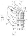
- Fig. 2 is a cross-sectional view taken along the line A-A of Fig. 1.
- Reference numeral 110 denotes a condenser core portion of the condenser 100
- reference numeral 210 denotes a radiator core of the radiator 200.
- the condenser core portion 110 comprises condenser tubes 111 formed flat as passages for refrigerant and corrugated (waved) fins 112 which are brazed to the condenser tubes 111.
- the radiator core 210 has a similar construction to that of the condenser core portion 110 and comprises radiator tubes 211 disposed in parallel with the condenser tubes 111 and fins 212.
- Both the core portions 110, 210 are arranged in series in a direction in which air flows with a gap being provided between the core portions for cutting off heat conduction therebetween.
- louvers 113, 213 are formed in the fins 112, 212, respectively, for promoting heat exchange, and the louvers 113, 213 are formed in the fins through roll forming at the same time as the fins 112, 212 are formed.
- reference numeral 300 denotes a side plate constituting a reinforcement member for both the core portions 110, 210, and this core plate 300 is, as shown in Fig. 1, disposed along side edges of both the core portions 110, 210.
- the side plate 300 is integrally formed of a sheet aluminum into a shape having a U-shaped cross section.
- reference numeral 310 denotes a bracket for attaching the heat exchanger to an automotive vehicle.
- a first radiator tank 220 for distributing coolant to the respective radiator tubes 211 is disposed at one of ends of the radiator core portion 210 where the side plates 300 are not disposed, and a second radiator tank 230 for recovering the coolant from which heat has been removed after heat exchange.
- An inlet 221 is provided at an upper end portion of the first radiator 220 for allowing coolant from the engine to flow therefrom into the first radiator 220, whereas an outlet 231 is provided at a lower end portion of the second radiator 230 for allowing coolant to flow out therefrom toward the engine.
- reference numerals 222, 232 denote joining pipes, respectively, for joining external piping (not shown) to the respective radiator tanks 220, 230, and these joining pipes 222, 232 are joined to the respective radiator tanks 220, 230 through brazing.
- reference numeral 120 denotes a first condenser tank for distributing refrigerant in the condenser core portion 110 to the respective condenser tubes 111
- reference numeral 130 denotes a second condenser tank of the condenser core portion 110 for recovering refrigerant from which heat has been carried away after heat exchange (condensation).
- Reference numeral 121 denotes an inlet for allowing refrigerant discharged from a compressor (not shown) in the refrigerating cycle to flow therefrom into the first condenser tank 120
- reference numeral 131 denotes an outlet for allowing refrigerant from which heat has been carried away after heat exchange (condensation) to flow out therefrom toward an expansion valve (not shown).
- reference numerals 122, 132 denote, respectively, joining pipes for joining external piping (not shown) to both the condenser tanks 120, 130, and these joining pipes 122, 132 are joined to the respective condenser tanks 120, 130 through brazing.
- the second radiator tank 230 are constituted by a radiator core plate 233 made of aluminum which connects to the radiator tubes 211, a radiator tank member 235 made of aluminum which connects to the radiator core plate 233 so as to form an angular pipe-like radiator tank main body 234 which is to be filled with coolant and radiator tank caps 236 for closing longitudinal ends of the radiator tank main body 234, and these members 233, 235, 236 are integrally connected to each other through brazing.
- the first condenser tank 120 is constructed so as to have a tubular condenser tank main body (a radiator tank main body) 123 made of aluminum and having an oval cross section which connects to the condenser tubes 111 and forms the space of the first condenser tank 120 and condenser caps (radiator caps) 124 (refer to Fig. 1) for closing longitudinal ends of the condenser tank main body 123.
- a tubular condenser tank main body a radiator tank main body
- condenser caps radiatator caps
- flat condenser tube inserting holes (first inserting holes) 125 are formed in the condenser tank main body 123 (the first condenser tank 120) so that the condenser tubes 111 are inserted thereinto, whereas flat radiator tube inserting holes (second inserting holes) 237 are formed in the radiator core plate 233 (the second radiator tank 230) so that the radiator tubes 211 are inserted thereinto.
- both the tanks 120, 230 are made integral with (connect to) each other at a connecting portion 400 where a major axial end of the condenser tube inserting hole 125 connects to a major axial end of the radiator tube inserting hole 237.
- the connecting portion 400 is bent into a U or V shape so as to protrude toward both core portions 110, 210, and is formed such that at least a distal end (a bent portion) 401 of the connecting portion 400 is positioned closer to the condenser core portion 110 than to the first condenser tank 120 as viewed from an upstream side of the air flow.
- the cross-sectional area of the condenser tank main body 123 and the cross-sectional area of the radiator core plate 233 are selected such that they become substantially equal to each other, and the condenser tank main body 123 and the radiator core plate 233 are formed integrally through extrusion or drawing together with the connecting portion 400.
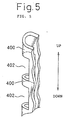
- the distal end 401 of the connecting portion 400 is partially removed through press cutting, whereby, as shown in Fig. 5, a plurality of cut-away portions 402 are formed between both the tanks 110, 210 dispersively in the longitudinal direction of both tanks 110, 210.
- the cut-away portions 402 are formed such that a ratio ( ⁇ L/LT) between the total sum of dimensions L (refer to Fig. 4) of portions of the connecting portion 400 which are parallel to the longitudinal direction of both the tanks 120, 230 and the longitudinal dimension LT of both the tanks 120, 230 becomes 0.5 or smaller.
- the radiator tank 230 is meant to include both the radiators 220, 230, and similarly, when used, the condenser tank is meant to include both the condenser tanks 120, 130.
- the condenser tank main body 123 and the radiator core plate 233 are formed integrally with each other of an aluminum material through extrusion or drawing. Note that in this process, as shown in Fig. 6A, a portion corresponding to the connecting portion 400 is not bent at an acute angle into a U or a V shape but is bent at substantially 90 degrees.
- the condenser tube inserting holes 125 are formed in the condenser tank main body 123 through machining. Then, the connecting portion 400 is partially press cut and removed to thereby form the cut-away portions 402, and after the radiator tube inserting holes 237 are formed, as shown in Fig. 6B, the connecting portion 400 is press bent further into the U or V shape.
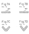
- a notch or notches 403 in a location corresponding to the distal end portion 401 of the connecting portion facilitates the bending of the location corresponding to the connecting portion 400, as shown in Fig. 7C or 7D.
- the radiator tank member 235 a brazing material is clad on one side of an aluminum core material (a base material), as shown in Fig. 8B, whereas a sacrificial layer material comprising a sacrificial material (zinc in this embodiment) having a lower electric potential than that of the core material is disposed to be clad on the other side of the core material, and when the brazing sheet material is press bent in a predetermined fashion, the radiator tank member 235 is formed so as to have an L-shaped cross section. Note that as this occurs, the radiator tank member 235 is press bent such that the side thereof where the sacrificial layer material is clad constitutes an internal surface of the radiator tank main body 234.
- the radiator tank member 235, the radiator core plate 233, both the tubes 111, 211, both the fins 112, 212, both the caps 124, 236 and the side plates 300 are assembled and fixed together as shown in Figs. 1, 3, 8A and are then heated, in an oven, so as to be joined together using a Nocolock(TM) brazing method.
- the heating temperature inside the oven is a temperature which is higher than the fusing points of the brazing material and the sacrificial layer material (zinc) and lower than that of the aluminum used as the core material.
- the fusing point of the core material ranges from 650 degrees C to 660 degrees C and those of the brazing material and the sacrificial layer material (zinc) are about 570 degrees C and about 420 degrees C, respectively
- the heating temperature is about 600 degrees C, the heating time being about 10 minutes after the heating temperature is reached although this depends upon the size of the heat exchanger heated.
- Nocolock(TM) brazing method is, as is well known, referred to as a method in which a flux for removing an oxide layer is applied to an aluminum material on which a brazing material is clad, and thereafter, the aluminum material is heat brazed in an atmosphere of an inert gas such as nitrogen.
- the corrosion preventing material (the sacrificial material) disposed and clad on the radiator tank member 235 is evaporated in a state in which the sacrificial layer material is confined in the radiator tank main body 234 constituted by the radiator tank member 235 and the radiator core plate 233.
- the evaporated sacrificial material (zinc) adheres to the internal surfaces of the radiator tank main body 234 including the internal surface of the radiator core plate 233 relatively uniformly without being radiated out of the radiator tank main body 234. Then, the sacrificial material (zinc) so adhering to the internal surfaces is radiated into the aluminum constituting the radiator tank main body 234, whereby an alloy layer (a corrosion preventing layer) containing the sacrificial material is heavily formed over the internal surface of the tank main body 234.
- the relatively uniform corrosion preventing layer can be formed on the internal surfaces of the radiator tank main body 234 with ease.
- a heat exchanger can be realized which is light in weight and low in production cost while the corrosion resistance of the heat exchanger is maintained.
- the radiator tank main body 234 is heated as a closed space by closing the openings of the radiator tank main body 234 with the radiator tank caps 236, the evaporated sacrificial material is assuredly prevented from being radiated out of the radiator tank main body 234, and the corrosion preventing layer can also be formed on the internal surfaces of the radiator caps 236 with ease. Consequently, it is ensured that the corrosion preventing layer can be formed on the internal surfaces of the radiator tank 230 without increasing the amount of the sacrificial material (zinc) uselessly.
- the corrosion preventing layer is formed at the same time as heating for brazing is implemented, no separate heating process is required for forming the corrosion preventing layer, whereby man hours for producing the heat exchanger can be reduced, and since the evaporated sacrificial material (zinc) enters the interior of the radiator tubes 211, the corrosion preventing layer can also be formed on internal surfaces of the radiator tubes 211.
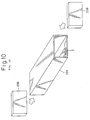
- radiator tank main body 234 is constituted by the two parts such as the radiator tank member 235 and the radiator core plate 233 in the first embodiment, in a second embodiment, as shown in Fig. 9, a radiator tank main body 234 is formed as an integral unit of an aluminum material through extrusion or drawing.
- a method for forming a corrosion preventing layer on internal surfaces of the radiator tank main body 234 according to the second embodiment will be described below.
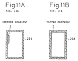
- an ingot Z of a sacrificial material (a zinc alloy containing zinc as a main constituent) is disposed inside the radiator tank main body 234.
- the radiator tank main body 234 is heat brazed after the other components such as radiator tank caps 266 and radiator tubes 211 have been tentatively assembled thereto.
- the evaporated sacrificial material is allowed, as shown in Figs. 11A and 11B, to adhere to the internal surfaces of the radiator tank main body 234 relatively uniformly without being radiated out of the radiator tank main body 234.
- the sacrificial material (zinc) so adhering to the internal surfaces is allowed to be radiated into aluminum constituting the radiator tank main body 234 to thereby form an alloy layer (a corrosion preventing layer) containing the sacrificial material (zinc) heavily on the internal surfaces of the radiator tank main body 234.
- radiator tank 230 which is filled with coolant and hence requires a corrosion preventing layer to be formed on the internal surfaces thereof, no corrosion preventing layer is required to be formed on the internal surfaces thereof as the condenser tank 120 is filled with refrigerant.
- both the tanks 123, 234 are integrally formed through extrusion or drawing in this embodiment, as described in the "Description of the Related Art", it is difficult to form a corrosion preventing layer on the internal surfaces of the radiator tank main body 234.
- the corrosion preventing layer can be formed only on the internal surfaces of the radiator tank main body 234 with ease, the embodiment is effective even if it is applied to a heat exchanger in which both the tanks 123, 234 are formed integrally through extrusion or drawing.
- both the radiator tank member 235 and the radiator core plate 233 may be formed of an aluminum material through extrusion or drawing and, as shown in Fig. 12, the sacrificial material may be flame sprayed on at least one of the radiator tank member 235 and the radiator core plate 233 to dispose the sacrificial material thereon.
- Nocolock(TM) brazing is used in the above embodiments, the present invention can be used with a vacuum brazing method.
- the corrosion preventing layer is formed on the internal surfaces of the angular pipe-like radiator tank main body 234 in the above embodiments, the present invention is not limited thereto but may be applied to a case where a corrosion preventing layer is formed on a round pipe-like tank, pipe, tube or the like.
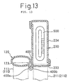
- heat exchangers according to the present invention may be applied, as shown in Fig. 13, to a duplex heat exchanger in which a radiator tank 230 incorporates therein an oil cooler 500 for cooling lubricating oil such as engine oil and transmission oil.
- the present invention may be applied solely to a single radiator.
- the sacrificial material when it is stated in this specification that "the sacrificial material is disposed inside the tank main body 234," it involves not only the disposition of the ingot Z of the sacrificial material inside the tank main body 234, as described in the second embodiment, but also the cladding of the core material with the corrosion preventing layer, as described in the first embodiment.
Landscapes
- Engineering & Computer Science (AREA)
- Mechanical Engineering (AREA)
- Physics & Mathematics (AREA)
- Thermal Sciences (AREA)
- General Engineering & Computer Science (AREA)
- Chemical & Material Sciences (AREA)
- Materials Engineering (AREA)
- Metallurgy (AREA)
- Organic Chemistry (AREA)
- Prevention Of Electric Corrosion (AREA)
- Heat-Exchange Devices With Radiators And Conduit Assemblies (AREA)
- Filling Or Discharging Of Gas Storage Vessels (AREA)
- Laminated Bodies (AREA)
Abstract
Description
Claims (11)
- A method for forming a corrosion preventing layer on internal surfaces of a metallic tank main body (234) which is filled with fluid; whereina sacrificial material is disposed within said tank main body (234) which comprises a metal having a lower electric potential than that of said tank main body (234), and whereinsaid sacrificial material is heated in a state in which said sacrificial material is surrounded by said tank main body (234).
- A method for forming a corrosion preventing layer as set forth in Claim 1, wherein said tank main body (234) is formed into a pipe-like shape through extrusion or drawing.
- A method for forming a corrosion preventing layer as set forth in Claim 1, wherein said sacrificial material is heated in a state in which said sacrificial material is disposed locally in the interior of said tank main body.
- A method for forming a corrosion preventing layer on internal surfaces of a metallic tank main body (234) which is filled with fluid; wherein
said tank main body (234) is constituted by at least two parts (233, 235), and wherein a sacrificial material comprising a metal having a lower electric potential than that of said tank main body (234) is disposed on part of an internal surface of at least one of said two parts (233, 235), said two parts (233, 235) being then assembled together, whereby said sacrificial material is heated in a state in which said sacrificial material is surrounded thereby. - A method for forming a corrosion preventing layer as set forth in Claim 4; wherein said part (235) of said two parts (233, 235) where said sacrificial material is disposed is formed through press working, the other part (233) being formed through extrusion or drawing.
- A method for forming a corrosion preventing layer as set forth in Claim 1 or 4; wherein said tank main body (234) is heated with a space within said tank main body (234) being closed by closing the openings of the radiator tank main body (234) with the radiator tank caps (236).
- A method for forming a corrosion preventing layer as set forth in Claim 4; wherein said sacrificial material is heated at the same time as said two parts (233, 235) or said caps (236) are brazed.
- A method for forming a corrosion preventing layer as set forth in Claim 4; wherein said sacrificial material is disposed by flame spraying a metal having a lower electric potential than that of said tank main body (234).
- A method for forming a corrosion preventing layer as set forth in Claim 1 or 4; wherein aluminum metal is used for said tank main body (234), and wherein
zinc is used as said metal having a lower electric potential than that of said tank main body (234). - A heat exchanger comprising:a plurality of tubes (211) for allowing fluid to flow therethrough; andmetallic header tanks (230) disposed at longitudinal ends of said plurality of tubes (211) for communication with said tubes (211), whereinsaid header tanks (230) are each constituted by a tank main body (234) extending in a direction normal to a longitudinal direction of said tubes (211) and caps (236) for closing the longitudinal ends of said tank main body (234), and whereinsaid tank main body (234) and said caps (236) are joined together through heat brazing with a sacrificial material comprising a metal having a lower electric potential than that of said tank main body (234) being disposed in the interior of said tank main body (234).
- A heat exchanger comprising:a plurality of radiator tubes (211) for allowing coolant to flow therethrough;metallic radiator header tanks (230) disposed at longitudinal ends of said plurality of tubes (211) for communication with said tubes (211);a plurality of radiator tubes (111) for allowing refrigerant to flow therethrough; andmetallic radiator header tanks (120) disposed at longitudinal ends of said plurality of radiator tubes (111) for communication with said tubes (111); whereinsaid radiator header tanks (230) are each constituted by a radiator tank main body (234) extending in a direction normal to a longitudinal direction of said radiator tubes (211) and radiator caps (236) for closing the longitudinal ends of said tank main body (234); whereinsaid radiator header tanks (120) are each constituted by a radiator tank main body (123) extending in a direction normal to a longitudinal direction of said radiator tubes (111) and radiator caps (124) for closing the longitudinal ends of said radiator tank main body (123); whereinboth said tank main bodies (123, 234) are made integrally with each other through extrusion or drawing; and whereinsaid radiator tank main bodies (123, 234) and said radiator caps (236) are joined to each other through heat brazing with a sacrificial material comprising a metal having a lower electric potential than that of said radiator tank main body (234) being disposed in the interior of said radiator tank main body (234).
Applications Claiming Priority (3)
| Application Number | Priority Date | Filing Date | Title |
|---|---|---|---|
| JP30020699 | 1999-10-21 | ||
| JP30020699A JP4399925B2 (en) | 1999-10-21 | 1999-10-21 | Method for forming sacrificial corrosion layer, heat exchanger, and dual heat exchanger |
| PCT/JP2000/007355 WO2001029497A1 (en) | 1999-10-21 | 2000-10-20 | Sacrifice corrosion layer forming method |
Publications (3)
| Publication Number | Publication Date |
|---|---|
| EP1146311A1 true EP1146311A1 (en) | 2001-10-17 |
| EP1146311A4 EP1146311A4 (en) | 2005-07-13 |
| EP1146311B1 EP1146311B1 (en) | 2010-11-24 |
Family
ID=17882011
Family Applications (1)
| Application Number | Title | Priority Date | Filing Date |
|---|---|---|---|
| EP00969971A Expired - Lifetime EP1146311B1 (en) | 1999-10-21 | 2000-10-20 | Sacrifice corrosion layer forming method |
Country Status (6)
| Country | Link |
|---|---|
| US (1) | US6601644B2 (en) |
| EP (1) | EP1146311B1 (en) |
| JP (1) | JP4399925B2 (en) |
| KR (1) | KR100436070B1 (en) |
| DE (1) | DE60045275D1 (en) |
| WO (1) | WO2001029497A1 (en) |
Cited By (2)
| Publication number | Priority date | Publication date | Assignee | Title |
|---|---|---|---|---|
| FR2840396A1 (en) * | 2002-05-28 | 2003-12-05 | Valeo Thermique Moteur Sa | DEVICE FOR PROTECTING A HEAT EXCHANGER AGAINST CORROSION |
| WO2020208119A1 (en) * | 2019-04-11 | 2020-10-15 | Valeo Systemes Thermiques | Fixing device for exchangers of a heat exchange system of a vehicle |
Families Citing this family (9)
| Publication number | Priority date | Publication date | Assignee | Title |
|---|---|---|---|---|
| TW552382B (en) * | 2001-06-18 | 2003-09-11 | Showa Dendo Kk | Evaporator, manufacturing method of the same, header for evaporator and refrigeration system |
| US6883502B2 (en) * | 2003-06-16 | 2005-04-26 | Caterpillar Inc. | Fluid/liquid heat exchanger with variable pitch liquid passageways and engine system using same |
| DE10339663A1 (en) * | 2003-08-28 | 2005-03-24 | Behr Gmbh & Co. Kg | Heat exchanger unit for motor vehicles |
| US7722922B2 (en) * | 2003-10-20 | 2010-05-25 | Furukawa-Sky Aluminum Corp. | Coating apparatus for an aluminum alloy heat exchanger member, method of producing a heat exchanger member, and aluminum alloy heat exchanger member |
| KR100619239B1 (en) * | 2004-06-02 | 2006-08-31 | 한국델파이주식회사 | THC integrated heat exchanger |
| CN101663554B (en) | 2007-04-05 | 2011-11-16 | 达纳加拿大公司 | Heat exchanger construction |
| SG10201506489XA (en) * | 2015-08-18 | 2017-03-30 | Mastercard International Inc | Method And System For Providing A Travel Recommendation |
| US20220338886A1 (en) | 2019-06-19 | 2022-10-27 | Think Surgical, Inc. | System and method to position a tracking system field-of-view |
| EP4060277A1 (en) * | 2021-03-17 | 2022-09-21 | Valeo Autosystemy SP. Z.O.O. | A heat exchanger |
Family Cites Families (19)
| Publication number | Priority date | Publication date | Assignee | Title |
|---|---|---|---|---|
| US3960208A (en) * | 1974-02-04 | 1976-06-01 | Swiss Aluminium Ltd. | Process for providing heat transfer with resistance to erosion-corrosion in aqueous environment |
| JPS5950269B2 (en) * | 1980-05-23 | 1984-12-07 | 住友軽金属工業株式会社 | Coating composition for corrosion protection on the inner surface of heat exchanger tubes |
| JPS5971998A (en) * | 1982-10-19 | 1984-04-23 | Nippon Denso Co Ltd | Aluminum heat exchanger |
| US5246064A (en) * | 1986-07-29 | 1993-09-21 | Showa Aluminum Corporation | Condenser for use in a car cooling system |
| JP2648311B2 (en) * | 1987-11-28 | 1997-08-27 | 大阪瓦斯株式会社 | Smoke tube heat recovery heat exchanger |
| JP2564190B2 (en) * | 1988-09-12 | 1996-12-18 | 株式会社神戸製鋼所 | Aluminum alloy composite for brazing |
| JPH0616308Y2 (en) * | 1989-03-08 | 1994-04-27 | サンデン株式会社 | Heat exchanger |
| US5152339A (en) * | 1990-04-03 | 1992-10-06 | Thermal Components, Inc. | Manifold assembly for a parallel flow heat exchanger |
| JPH06272069A (en) * | 1993-03-22 | 1994-09-27 | Nippon Light Metal Co Ltd | Corrosion protection of Al alloy radiator using sacrificial anode |
| JPH07314177A (en) * | 1994-03-28 | 1995-12-05 | Mitsubishi Alum Co Ltd | Brazing composition, Al material provided with the brazing composition, and heat exchanger |
| US5544698A (en) * | 1994-03-30 | 1996-08-13 | Peerless Of America, Incorporated | Differential coatings for microextruded tubes used in parallel flow heat exchangers |
| JPH0933190A (en) * | 1995-07-20 | 1997-02-07 | Denso Corp | Stacked heat exchanger |
| JP3674120B2 (en) * | 1995-11-29 | 2005-07-20 | 株式会社デンソー | Heat exchanger |
| JP3857791B2 (en) * | 1996-11-19 | 2006-12-13 | カルソニックカンセイ株式会社 | Heat exchanger tank |
| JP3370531B2 (en) * | 1996-11-22 | 2003-01-27 | カルソニックカンセイ株式会社 | Corrosion protection method for inner surface of aluminum alloy heat transfer tube |
| JP3810875B2 (en) * | 1997-01-24 | 2006-08-16 | カルソニックカンセイ株式会社 | Integrated heat exchanger |
| JPH11142078A (en) * | 1997-11-06 | 1999-05-28 | Denso Corp | Aluminum heat exchanger and method of manufacturing the same |
| JPH11148794A (en) * | 1997-11-14 | 1999-06-02 | Zexel:Kk | Heat exchanger |
| DE69902614T2 (en) * | 1998-10-19 | 2003-08-07 | Denso Corp., Kariya | Double heat exchanger, with condenser and radiator |
-
1999
- 1999-10-21 JP JP30020699A patent/JP4399925B2/en not_active Expired - Fee Related
-
2000
- 2000-10-20 EP EP00969971A patent/EP1146311B1/en not_active Expired - Lifetime
- 2000-10-20 WO PCT/JP2000/007355 patent/WO2001029497A1/en not_active Ceased
- 2000-10-20 KR KR10-2001-7007778A patent/KR100436070B1/en not_active Expired - Fee Related
- 2000-10-20 DE DE60045275T patent/DE60045275D1/en not_active Expired - Lifetime
-
2001
- 2001-06-20 US US09/885,549 patent/US6601644B2/en not_active Expired - Lifetime
Cited By (7)
| Publication number | Priority date | Publication date | Assignee | Title |
|---|---|---|---|---|
| FR2840396A1 (en) * | 2002-05-28 | 2003-12-05 | Valeo Thermique Moteur Sa | DEVICE FOR PROTECTING A HEAT EXCHANGER AGAINST CORROSION |
| WO2003100337A3 (en) * | 2002-05-28 | 2004-04-01 | Valeo Thermique Moteur Sa | Device for protecting a heat exchanger against corrosion |
| WO2020208119A1 (en) * | 2019-04-11 | 2020-10-15 | Valeo Systemes Thermiques | Fixing device for exchangers of a heat exchange system of a vehicle |
| FR3095037A1 (en) * | 2019-04-11 | 2020-10-16 | Valeo Systemes Thermiques | Fastening device for heat exchangers of a vehicle heat exchange system |
| CN113874672A (en) * | 2019-04-11 | 2021-12-31 | 法雷奥热系统公司 | Fixing device for heat exchanger of vehicle heat exchange system |
| CN113874672B (en) * | 2019-04-11 | 2024-03-29 | 法雷奥热系统公司 | Fixing device for a heat exchanger of a vehicle heat exchange system |
| US12467702B2 (en) | 2019-04-11 | 2025-11-11 | Valeo Systemes Thermiques | Fixing device for heat exchangers of a vehicle heat exchange system |
Also Published As
| Publication number | Publication date |
|---|---|
| DE60045275D1 (en) | 2011-01-05 |
| JP4399925B2 (en) | 2010-01-20 |
| EP1146311A4 (en) | 2005-07-13 |
| KR20010099846A (en) | 2001-11-09 |
| US6601644B2 (en) | 2003-08-05 |
| JP2001116489A (en) | 2001-04-27 |
| US20020005278A1 (en) | 2002-01-17 |
| WO2001029497A1 (en) | 2001-04-26 |
| EP1146311B1 (en) | 2010-11-24 |
| KR100436070B1 (en) | 2004-06-12 |
Similar Documents
| Publication | Publication Date | Title |
|---|---|---|
| EP1172623B1 (en) | Heat exchanger and fluid pipe therefor | |
| US5678628A (en) | Heat exchanger and method for manufacturing the same | |
| US6006430A (en) | Aluminum heat exchanger | |
| CN100425939C (en) | Heat exchanger, pipe material and fin material of heat exchanger and manufacturing method of heat exchanger | |
| EP0881449A2 (en) | Refrigerant tubes for heat exchangers | |
| JPH11311497A (en) | Double heat exchanger | |
| JP2000304488A (en) | Aluminum alloy heat exchanger | |
| US20020189799A1 (en) | Heat exchanger | |
| EP1146311B1 (en) | Sacrifice corrosion layer forming method | |
| US6173765B1 (en) | Heat exchange having header tank | |
| JP3829494B2 (en) | Heat exchanger | |
| US20170198975A1 (en) | Heat Exchanger Construction | |
| KR20020001605A (en) | Heat exchanger having plural tubes connected to header tanks by brazing | |
| US12590769B2 (en) | Heat exchanger with aluminum alloy clad tube and method of manufacture | |
| JPH10103893A (en) | Heat exchange equipment | |
| CN101487673B (en) | Tube for heat exchanger | |
| US20060162919A1 (en) | Flat tube and process for producing heat exchanger with use of the flat tube | |
| US5238059A (en) | Heat exchanger header with parallel edges | |
| US20080264620A1 (en) | Flat Tube, Platelike Body for Making the Flat Tube and Heat Exchanger | |
| JP2001330391A (en) | Heat exchanger | |
| JP2000158070A (en) | Heat exchanger tubes | |
| US20070204982A1 (en) | Manifolds and manifold connections for heat exchangers | |
| JP5066709B2 (en) | Manufacturing method of flat tube | |
| JP4058825B2 (en) | Double heat exchanger | |
| JP2004069258A (en) | Flat tube, and method of manufacturing heat exchanger using flat tube |
Legal Events
| Date | Code | Title | Description |
|---|---|---|---|
| PUAI | Public reference made under article 153(3) epc to a published international application that has entered the european phase |
Free format text: ORIGINAL CODE: 0009012 |
|
| 17P | Request for examination filed |
Effective date: 20010620 |
|
| AK | Designated contracting states |
Kind code of ref document: A1 Designated state(s): AT BE CH CY DE DK ES FI FR GB GR IE IT LI LU MC NL PT SE |
|
| RBV | Designated contracting states (corrected) |
Designated state(s): DE FR |
|
| RAP1 | Party data changed (applicant data changed or rights of an application transferred) |
Owner name: DENSO CORPORATION Owner name: FURUKAWA-SKY ALUMINUM CORP. |
|
| A4 | Supplementary search report drawn up and despatched |
Effective date: 20050527 |
|
| RIC1 | Information provided on ipc code assigned before grant |
Ipc: 7F 28F 19/06 A Ipc: 7C 23C 10/30 B Ipc: 7F 28D 1/04 B Ipc: 7C 23C 10/18 B Ipc: 7C 23F 13/00 B Ipc: 7F 28F 21/08 B |
|
| GRAP | Despatch of communication of intention to grant a patent |
Free format text: ORIGINAL CODE: EPIDOSNIGR1 |
|
| GRAS | Grant fee paid |
Free format text: ORIGINAL CODE: EPIDOSNIGR3 |
|
| GRAA | (expected) grant |
Free format text: ORIGINAL CODE: 0009210 |
|
| AK | Designated contracting states |
Kind code of ref document: B1 Designated state(s): DE FR |
|
| REF | Corresponds to: |
Ref document number: 60045275 Country of ref document: DE Date of ref document: 20110105 Kind code of ref document: P |
|
| PLBE | No opposition filed within time limit |
Free format text: ORIGINAL CODE: 0009261 |
|
| STAA | Information on the status of an ep patent application or granted ep patent |
Free format text: STATUS: NO OPPOSITION FILED WITHIN TIME LIMIT |
|
| 26N | No opposition filed |
Effective date: 20110825 |
|
| REG | Reference to a national code |
Ref country code: DE Ref legal event code: R097 Ref document number: 60045275 Country of ref document: DE Effective date: 20110825 |
|
| REG | Reference to a national code |
Ref country code: FR Ref legal event code: PLFP Year of fee payment: 16 |
|
| PGFP | Annual fee paid to national office [announced via postgrant information from national office to epo] |
Ref country code: DE Payment date: 20151022 Year of fee payment: 16 |
|
| PGFP | Annual fee paid to national office [announced via postgrant information from national office to epo] |
Ref country code: FR Payment date: 20151023 Year of fee payment: 16 |
|
| REG | Reference to a national code |
Ref country code: DE Ref legal event code: R119 Ref document number: 60045275 Country of ref document: DE |
|
| REG | Reference to a national code |
Ref country code: FR Ref legal event code: ST Effective date: 20170630 |
|
| PG25 | Lapsed in a contracting state [announced via postgrant information from national office to epo] |
Ref country code: FR Free format text: LAPSE BECAUSE OF NON-PAYMENT OF DUE FEES Effective date: 20161102 Ref country code: DE Free format text: LAPSE BECAUSE OF NON-PAYMENT OF DUE FEES Effective date: 20170503 |