EP1145954A1 - Vorrichtung sowie Verfahren zur Reduzierung von Nachlaufwirbeln hinter Flugzeugen im Landeanflug - Google Patents
Vorrichtung sowie Verfahren zur Reduzierung von Nachlaufwirbeln hinter Flugzeugen im Landeanflug Download PDFInfo
- Publication number
- EP1145954A1 EP1145954A1 EP01108685A EP01108685A EP1145954A1 EP 1145954 A1 EP1145954 A1 EP 1145954A1 EP 01108685 A EP01108685 A EP 01108685A EP 01108685 A EP01108685 A EP 01108685A EP 1145954 A1 EP1145954 A1 EP 1145954A1
- Authority
- EP
- European Patent Office
- Prior art keywords
- wing
- vortex
- flap
- additional flap
- additional
- Prior art date
- Legal status (The legal status is an assumption and is not a legal conclusion. Google has not performed a legal analysis and makes no representation as to the accuracy of the status listed.)
- Granted
Links
- 238000000034 method Methods 0.000 title claims abstract description 17
- 238000013459 approach Methods 0.000 title description 6
- 230000002452 interceptive effect Effects 0.000 claims abstract description 6
- 230000000694 effects Effects 0.000 claims description 6
- 230000015572 biosynthetic process Effects 0.000 description 4
- 238000005755 formation reaction Methods 0.000 description 4
- 238000013461 design Methods 0.000 description 2
- 238000004090 dissolution Methods 0.000 description 2
- 230000006378 damage Effects 0.000 description 1
- 238000011161 development Methods 0.000 description 1
- 230000018109 developmental process Effects 0.000 description 1
- 230000007246 mechanism Effects 0.000 description 1
- 230000002028 premature Effects 0.000 description 1
- 238000011160 research Methods 0.000 description 1
Images


Classifications
-
- B—PERFORMING OPERATIONS; TRANSPORTING
- B64—AIRCRAFT; AVIATION; COSMONAUTICS
- B64C—AEROPLANES; HELICOPTERS
- B64C23/00—Influencing air flow over aircraft surfaces, not otherwise provided for
- B64C23/06—Influencing air flow over aircraft surfaces, not otherwise provided for by generating vortices
-
- Y—GENERAL TAGGING OF NEW TECHNOLOGICAL DEVELOPMENTS; GENERAL TAGGING OF CROSS-SECTIONAL TECHNOLOGIES SPANNING OVER SEVERAL SECTIONS OF THE IPC; TECHNICAL SUBJECTS COVERED BY FORMER USPC CROSS-REFERENCE ART COLLECTIONS [XRACs] AND DIGESTS
- Y02—TECHNOLOGIES OR APPLICATIONS FOR MITIGATION OR ADAPTATION AGAINST CLIMATE CHANGE
- Y02T—CLIMATE CHANGE MITIGATION TECHNOLOGIES RELATED TO TRANSPORTATION
- Y02T50/00—Aeronautics or air transport
- Y02T50/10—Drag reduction
Definitions
- the invention relates to a device and a method for reducing Caster vortexes behind aircraft that are approaching landing, which Aircraft to generate lift a right and a left wing having high lift systems.
- high-lift systems are necessary to for example, on approach to generate the necessary lift.
- Such high-lift systems usually consist of slats and Flaps.
- a wing creates lift, it arises behind the wing always a wake with vortices. It initially forms in Area of the outer end of each flap a flap vortex as well a vertebra in the wing tip area.
- This vortex system rotates around each other, at the same time, the individual vertebrae rotate around themselves, the whole Vortex system carried away in a spiral movement with the flow becomes.
- the vortices generated by large transport aircraft pose a danger for the subsequent air traffic, especially on the densely flown Approach routes.
- Prescribed safety distances between approaching Airplanes reduce the risk, but also limit the capacity of one Runway, because the necessary horizontal to maintain flight safety
- the goal is therefore aimed at measures on the aircraft, the wake vortices reduce and promote their early dissolution.
- the present invention is therefore based on the object of a generic To design the device and a generic method so that Caster vortices behind aircraft that are approaching landing are reduced and an early dissolution of such vortices is promoted.
- the device according to the invention is particularly advantageous that with the device according to the invention or the method according to the invention the emergence of a dangerous Vortex flow is prevented behind aircraft on landing and thus the Aviation security is increased.
- the safety distances between the landing aircraft can be reduced, which can reduce the capacity of a Runway increased and thus takes into account the growing air traffic.
- the device according to the invention is particularly advantageous that for large aircraft with a high weight, for which currently a vertebral hazard is seen as a major problem in aviation.
- the sub-claim 2 shows the advantageous embodiment of the device as Additional flap, which is designed as a simple small component and is Can easily be accommodated on the wing when not in use.
- the advantageous attachment point on the wing is also indicated.
- the sub-claims 3 and 4 give the for the effect as a vortex generator advantageous angle of attack of the additional flap.
- Formations of the additional flap are specified in subclaims 5 to 8, which a controlled leading edge vortex to form an interfering vortex on the Generate additional flap.
- the Additional flap has the shape of a delta wing, two arise in opposite directions rotating vertebrae as a pair of vertebrae that form the disturbing vortex.
- Claims 9 to 11 are directed to an aircraft, the possible Arrangements of the device according to the invention on the aircraft wings are specified.
- the subclaims 14 to 16 give alternative procedures for operation of the additional flaps according to the invention on an aircraft.
- FIGS. 1 to 5 In the drawing, embodiments of the invention are shown, the following are described in more detail with reference to FIGS. 1 to 5.
- FIGS. 1 to 5 In the figures are Identical components with the same reference numerals.
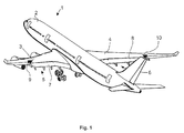
- FIG. 1 An aircraft 1 can be seen in a perspective view in FIG. 1.
- the plane 1 is as a subsonic transport plane, especially for transportation provided by passengers.
- Each wing 3 or 4 points to generating the necessary lift during slow flight, for example on approach, high-lift systems 5 and 6 respectively.
- Such high-lift systems 5 and 6 have flaps 7 and 8, among other things.
- On Each wing 3 and 4 is an inventive device 9 and 10 for Reduction of wake vortices provided, their arrangement, shape and Mode of operation is described in more detail in the following figures.
- FIGS. 2A and 2B planes with trailing vortices are shown in a view from above.
- a basic configuration of the aircraft 1 can be seen in FIG. 2A, the wake vortices 11 and 12 which essentially arise on the left wing 3 and on the right wing 4 being recognizable by means of arrows by indicating their course and their direction of rotation.
- a flap vortex 11B or 12B is formed on the trailing edge 3B or 4B in the region of the eddy flow converging on the trailing edge.
- the "weak point" of the swirling flow is the outer end 7A or 8A of the extended landing flap 7 of the wing 3 or the landing flap 8 of the wing 4 in the direction of the span or 12B is essentially the large vortex that brings with it the disadvantages already mentioned for subsequent air traffic.
- a controlled generated interference flow is introduced into the process of creating the wake flow. This already disrupts the creation of the dangerous eddy current.
- the device for reducing wake vortices 9 or 10 - referred to in the following additional flap 9 or 10 - is provided, which is located on the wing 3 or 4 in the region of the flap end 7A or 8A of the landing flaps 7 or 8 is arranged.
- the (small, controlled generated) interference vortex 13 or 14 interferes with the converging vertebrae from the trailing edge of the wing 3B or 4B, ie essentially with the valve vortex 11B or 12B.
- the mode of operation of an interfering vortex 13 or 14 is explained in more detail below:
- the additional surface (vortex generator) 9 or 10 which is preferably set at 15 to 25 degrees (relative to the retracted state), produces a controlled front edge vortex on its front edge on the suction side Leading edge is fed.
- This vortex leaves the additional surface 9 or 10 at its rear edge and interferes as a free interfering vortex 13 or 14 with the valve vortex 11B or 12B, which is being created at the valve end 7A or 8A (by convergence of vortex strength, which along the rear edge as unstable fluidized bed flows out).
- the effect is so intense that the resulting valve vortex 11B or 12B is set in transverse vibrations and is considerably disturbed in its concentration process.
- the valve vortex 11B or 12B loses strength, the maximum vortex strength in the core of the resulting vortex in particular being considerably reduced, which can be clearly seen in FIG. 3, in particular in FIG. 3B.
- 3B shows the vortex intensity of the wake vortex 12 shown by way of example, the flap vortex 12B being strongly oscillating and therefore reduced in intensity as a result of the disturbing vortex 14.
- a vortex 12 disturbed in this way disintegrates prematurely.
- 3A shows the vortex intensity of wake vortices of an aircraft without a device 9 or 10 according to the invention.
- the wake vortex 11 or 12 of such an aircraft has a pronounced core, which expresses the tip in the middle of the vortex. The higher this tip, the greater the intensity of the vertebra.
- FIGS. 4A to 4C shows embodiments of the additional flap 9 according to the invention (also corresponds to the additional flap 10 on the wing 4) in FIGS. 4A to 4C.
- the relatively small additional flap 9 is attached with its base 9 'on the wing 3 in the area of the flap end 7A of the landing flap 7 in preferably 60% to 80% of the profile depth of the base wing, the profile depth being a cut in the direction of flight through the base wing.
- the base point 9 'of the additional flap 9 is preferably in a region which, measured from the end of the flap 7A, extends on both sides to the left or right in each case 10% of the half-span. The distance from the center of the fuselage to the wing tip is defined as the half span.
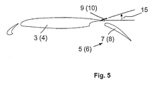
- the additional flap 9 must be placed in the flow for the duration of its action, the preferred setting angle being shown in FIG. 5.
- the additional flap 9 is shaped so that a controlled (small) vortex is formed on its front edge, which represents a high turbulent vortex flow when leaving the additional flap 9.
- This high-energy flow leaves the additional flap 9 and penetrates into the "weak point" of the resulting wake, ie it stimulates the wake vortex to intense vibrations and suppresses the concentration process, which would otherwise lead to a strong wake vane 11.
- the additional flap 9 (or 10) acts as a passive component, ie it is extended and remains stationary during the approach.
- 4A shows a first preferred form of the additional flap 9.
- the additional flap 9 has the shape 9A of a wing of small extension with approximately 60 degrees leading edge sweep on one side on the left. The other side is preferably unswept.
- 4B shows another possible form 9B.
- the additional flap 9 is formed here as a wing with a small extension with approximately 60 degrees leading edge sweep on one side on the right, the other side is unswept.
- a third embodiment 9C is shown in Fig. 4C. This embodiment 9C is characterized by a wing of small extension with approximately 60 degrees leading edge sweep on both sides (delta wing).
- a delta wing as an additional flap, two counter-rotating vortices are created as a pair of vertebrae, which are controlled as disturbing vortices and are intended to disrupt the formation of the wake vortices.
- the swept front edges are preferably sharpened like a knife edge in order to force the stall.
- the swept front edges are preferably straight, but can also be curved, similar to the wing of the Concorde supersonic aircraft.
- the rear edge of the additional flap 9A, 9B or 9C is preferably straight and is preferably perpendicular to the direction of flight.
- the flaps 7 and 8 as part of the high-lift system 5 and 6 can be seen.
- the additional flap 9 or 10 is used for the approach extended, the setting angle 15 of the additional flap 9 or 10 opposite the top of the wing 3 or 4 preferably between 12 to 25 degrees should be. If the angle of attack is above 30 degrees, it can result in a uncontrolled stall, which is especially for the formation of the controlled vortex 13 or 14 is undesirable.
Landscapes
- Engineering & Computer Science (AREA)
- Aviation & Aerospace Engineering (AREA)
- Toys (AREA)
- Aerodynamic Tests, Hydrodynamic Tests, Wind Tunnels, And Water Tanks (AREA)
- Structures Of Non-Positive Displacement Pumps (AREA)
- Radar Systems Or Details Thereof (AREA)
- Traffic Control Systems (AREA)
- Turbine Rotor Nozzle Sealing (AREA)
Abstract
Description
Aus GB 2 051 706 A1 ist eine Einrichtung direkt am Ende einer Landeklappe vorgesehen, die den Widerstand des Flugzeuges verringern soll. Auch ist vorgesehen, dass mit Nutzung solcher Einrichtung die Nachlaufwirbel reduziert werden. Die Vorrichtung ist jedoch nicht geeignet, einen kontrollierten Störwirbel zu erzeugen wie mit der hier vorgeschlagenen Erfindung. Die Art und Weise der Wirbelminderung wird nicht mitgeteilt.
Ein gattungsgemäßes Verfahren ist im Patentanspruch 12 angegeben.
- Fig. 1
- ein Flugzeug in perspektivischer Darstellung mit einer erfindungsgemäßen Vorrichtung zur Reduzierung der Nachlaufwirbel,
- Fig. 2
- eine Darstellung von Flugzeugen in der Ansicht von oben, wobei in Fig. 2A ein Flugzeug in einer Basiskonfiguration und in Fig. 2B ein Flugzeug mit der erfindungsgemäßen Vorrichtung ersichtlich ist,
- Fig. 3
- eine Darstellung von Flugzeugen mit entstehenden Nachlaufwirbeln in der Ansicht von oben, wobei in Fig. 3A Wirbel des Flugzeugs in einer Basiskonfiguration und in Fig. 3B Wirbel des Flugzeugs mit der erfindungsgemäßen Vorrichtung ersichtlich ist,
- Fig. 4
- zeigt in den Figuren 4A, 4B, 4C jeweils Ausführungsformen der
erfindungsgemäßen Vorrichtung
und - Fig. 5
- einen Querschnitt durch den Tragflügel mit einer erfindungsgemäßen Vorrichtung.
Um die Wirbelintensität dieses Großwirbels zu reduzieren, wird erfindungsgemäß eine kontrolliert erzeugte Störströmung in den Entstehungsvorgang der Nachlaufströmung eingebracht. Damit wird bereits das Entstehen der gefährlichen Wirbelströmung gestört. Zur Generierung eines Störwirbels 13 bzw. 14 ist die Vorrichtung zur Reduzierung von Nachlaufwirbeln 9 bzw. 10 - im nachfolgenden Zusatzklappe 9 bzw. 10 bezeichnet - vorgesehen, die auf dem Tragflügel 3 bzw. 4 im Bereich des Klappenendes 7A bzw. 8A der Landeklappen 7 bzw. 8 angeordnet ist. In der vergrößerten Darstellung von Fig. 2B ist ersichtlich, dass der (kontrolliert erzeugte kleine) Störwirbel 13 bzw. 14 mit den zusammenlaufenden Wirbeln von der Flügelhinterkante 3B bzw. 4B, d.h. im wesentlichen mit dem Klappenwirbel 11B bzw. 12B interferiert. Die Wirkungsweise eines Störwirbels 13 oder 14 wird nachfolgend näher erläutert: Die bevorzugt auf 15 bis 25 Grad (relativ zum eingefahrenen Zustand) angestellte Zusatzfläche (Wirbelgenerator) 9 bzw. 10 erzeugt an ihrer Vorderkante auf der Saugseite einen kontrollierten Vorderkantenwirbel, der aus abgelöster Strömung der Vorderkante gespeist wird. Dieser Wirbel verlässt die Zusatzfläche 9 bzw. 10 an ihrer Hinterkante und interferiert als freier Störwirbel 13 bzw. 14 mit dem Klappenwirbel 11B bzw. 12B, der am Klappenende 7A bzw. 8A im Entstehen ist (durch Zusammenlaufen von Wirbelstärke, die entlang der Hinterkante als instabile Wirbelschicht abströmt). Die Wirkung ist so intensiv, dass der entstehende Klappenwirbel 11B bzw. 12B in Querschwingungen versetzt wird und dabei in seinem Konzentrationsprozess erheblich gestört wird. Infolge der Schwingungen verliert der Klappenwirbel 11B bzw. 12B an Stärke, wobei insbesondere die maximale Wirbelstärke im Kern des resultierenden Wirbels erheblich reduziert wird, was in Fig. 3, insbesondere in Fig. 3B gut erkennbar ist. In Fig. 3B ist die Wirbelintensität vom beispielhaft gezeigten Nachlaufwirbel 12 gezeigt, wobei infolge des Störwirbels 14 der Klappenwirbel 12B stark oszillierend und damit in seiner Intensität reduziert ist. Ein derart gestörter Wirbel 12 zerfällt vorzeitig. In Fig. 3A ist demgegenüber die Wirbelintensität von Nachlaufwirbeln eines Flugzeuges ohne eine erfindungsgemäße Vorrichtung 9 bzw. 10 gezeigt. Der Nachlaufwirbel 11 bzw. 12 eines solchen Flugzeuges weist einen ausgeprägten Kern auf, was die Spitze in der Mitte des Wirbels ausdrückt. Je höher diese Spitze, umso größer ist die Intensität des Wirbels.
Die relativ kleine Zusatzklappe 9 wird mit ihrem Fußpunkt 9' auf dem Flügel 3 im Bereich des Klappenendes 7A der Landeklappe 7 in vorzugsweise 60% bis 80% der Profiltiefe des Basisflügels angebracht, wobei als Profiltiefe ein Schnitt in Flugrichtung durch den Basisflügel zu verstehen ist. Der Fußpunkt 9' der Zusatzklappe 9 liegt bevorzugt in einem Bereich, der vom Ende der Landeklappe 7A gemessen sich beidseitig nach links oder rechts jeweils 10% der Halbspannweite erstreckt. Als Halbspannweite ist der Abstand von Rumpfmitte zur Flügelspitze definiert.
Die Zusatzklappe 9 muss während der Dauer ihrer Wirkung in die Strömung angestellt werden, wobei der bevorzugte Anstellwinkel in Fig. 5 gezeigt ist. Die Zusatzklappe 9 ist so geformt, dass ein kontrollierter (kleiner) Wirbel an ihrer Vorderkante entsteht, der beim Verlassen der Zusatzklappe 9 eine hohe turbulente Wirbelströmung darstellt. Diese energiereiche Strömung verlässt die Zusatzklappe 9 und dringt in die "Schwachstelle" der entstehendenden Nachlaufströmung ein, d.h. regt den Nachlaufwirbel zu intensiven Schwingungen an und unterdrückt dabei den Konzentrationsprozess, der anderenfalls zu einen starken Nachlaufwirbel 11 führen würde.
In der bevorzugten Ausführung wirkt die Zusatzklappe 9 (bzw. 10) als passives Bauteil, d.h. sie wird ausgefahren und bleibt während des Anflugs stationär. Es ist jedoch ebenfalls möglich, die Zusatzklappe 9 dynamisch zu betreiben, d.h. wechselsinnig oder gleichsinnig mit der Zusatzklappe 10 am Tragflügel 4. Dadurch können Längsschwingungen im Wirbel oder asymmetrische Wirbel entstehen, die geeignet sind, den Zerfallsprozess weiter zu beschleunigen.
Die Fig. 4B zeigt eine weitere mögliche Form 9B. Die Zusatzklappe 9 ist hier als Flügel kleiner Streckung mit ungefähr 60 Grad Vorderkantenpfeilung einseitig rechts ausgebildet, die andere Seite ist ungepfeilt.
Eine dritte Ausführungsform 9C ist in Fig. 4C dargestellt. Diese Ausführungsform 9C ist gekennzeichnet durch einen Flügel kleiner Streckung mit ungefähr 60 Grad Vorderkantenpfeilung beidseitig (Deltaflügel). Bei einem Deltaflügel als Zusatzklappe entstehen zwei gegenläufig drehende Wirbel als Wirbelpaar, die als Störwirbel kontrolliert die Entstehung des Nachlaufwirbels stören sollen.
Allen drei Ausführungsformen ist gemeinsam, dass bevorzugt die gepfeilten Vorderkanten ähnlich einer Messerkante zugeschärft sind, um den Strömungsabriss zu erzwingen. Die gepfeilten Vorderkanten sind vorzugsweise geradlinig ausgebildet, können aber auch geschwungen sein, ähnlich wie der Tragflügel des Überschallflugzeuges Concorde. Die Hinterkante der Zusatzklappe 9A, 9B oder 9C ist vorzugsweise geradlinig ausgebildet und verläuft vorzugsweise senkrecht zur Flugrichtung.
- 1 -
- Flugzeug
- 2 -
- Flugzeugrumpf
- 3 -
- linker Tragflügel
- 3A -
- Flügelspitze
- 3B -
- Flügelhinterkante
- 4 -
- rechter Tragflügel
- 4A -
- Flügelspitze
- 4B -
- Flügelhinterkante
- 5 -
- Hochauftriebssystem (links)
- 6 -
- Hochauftriebssystem (rechts)
- 7 -
- Landeklappen (links)
- 7A -
- äußeres Klappenende
- 8 -
- Landeklappen (rechts)
- 8A -
- äußeres Klappenende
- 9 -
- Vorrichtung zur Reduzierung von Nachlaufwirbeln/Zusatzklappe
- 9' -
- Fußpunkt
- 10 -
- Vorrichtung zur Reduzierung von Nachlaufwirbeln/Zusatzklappe
- 11 -
- Nachlaufwirbel (links)
- 11A -
- Randwirbel
- 11B -
- Klappenwirbel
- 12 -
- Nachlaufwirbel (rechts)
- 12A -
- Randwirbel
- 12B -
- Klappenwirbel
- 13 -
- Zusatzwirbel (Störwirbel) - links
- 14 -
- Zusatzwirbel (Störwirbel) - rechts
- 15 -
- Anstellwinkel
Claims (16)
- Vorrichtung zur Reduzierung von Nachlaufwirbeln (11, 12) hinter Flugzeugen, wobei das Flugzeug (1) zur Auftriebserzeugung einen rechten und einen linken Tragflügel (3, 4) aufweist, die unter anderem Landeklappen (7, 8) als Hochauftriebssysteme (5, 6) umfassen, dadurch gekennzeichnet, dass am jeweiligen Tragflügel (3, 4) im Bereich der Flügelhinterkante (3B, 4B) in Nähe der äußeren, ausgefahrenen Landeklappenenden (7A, 8A) ein Wirbelgenerator (9, 10) zur Erzeugung eines kontrollierten Störwirbels (13, 14) angeordnet ist.
- Vorrichtung nach Anspruch 1, dadurch gekennzeichnet, dass der Wirbelgenerator als Zusatzklappe (9, 10) ausgebildet ist, deren Fußpunkt (9') in einem Bereich von 10% der Halbspannweite links und rechts des jeweiligen äußeren Landeklappenendes (7A, 8A) am Tragflügel (3, 4) sowie in Tiefenrichtung ab 60 % der Profiltiefe des Tragflügels (3,4) vorgesehen ist, wobei die Zusatzklappe (9, 10) für den Langsamflug einen ausgefahrenen Zustand einnimmt sowie bei Nichtgebrauch in den Flügel einklappbar ist.
- Vorrichtung nach einem der Ansprüche 1 oder 2, dadurch gekennzeichnet, dass die Zusatzklappe (9, 10) im ausgefahrenen Zustand einen Anstellwinkel (15) kleiner als 30 Grad relativ zur Ebene der Flügeloberseite aufweist.
- Vorrichtung nach Anspruch 3, dadurch gekennzeichnet, dass der Anstellwinkel (15) im Bereich zwischen 12 und 25 Grad liegt.
- Vorrichtung nach einem der Ansprüche 1 bis 4, dadurch gekennzeichnet, dass die Zusatzklappe (9, 10) in Form (9A) eines Flügels kleiner Streckung mit ungefähr 60 Grad Vorderkantenpfeilung einseitig links sowie die andere Seite ungepfeilt ausgebildet ist.
- Vorrichtung nach einem der Ansprüche 1 bis 4, dadurch gekennzeichnet, dass die Zusatzklappe (9, 10) in Form (9B) eines Flügels kleiner Streckung mit ungefähr 60 Grad Vorderkantenpfeilung einseitig rechts sowie die andere Seite ungepfeilt ausgebildet ist.
- Vorrichtung nach einem der Ansprüche 1 bis 4, dadurch gekennzeichnet, dass die Zusatzklappe (9, 10) in Form (9C) eines Flügels kleiner Streckung mit ungefähr 60 Grad Vorderkantenpfeilung beidseitig ausgebildet ist.
- Vorrichtung nach einem der Ansprüche 5 bis 7, dadurch gekennzeichnet, dass die mindestens eine gepfeilte Vorderkante der Zusatzklappe (9A, 9B oder 9C) zugeschärft ist und die Hinterkante der Zusatzklappe (9A, 9B oder 9C) vorzugsweise geradlinig ausgebildet ist.
- Flugzeug mit mindestens einer Vorrichtung gemäß der vorangegangenen Ansprüche, dadurch gekennzeichnet, dass die Zusatzklappe (9, 10) zur Wirkung im Langsamflug einen ausgefahrenen Zustand stationär einnimmt und dieser Zustand symmetrisch an jedem Tragflügel (3, 4) vorgesehen ist.
- Flugzeug mit mindestens einer Vorrichtung nach einem der Ansprüche 1 bis 8, dadurch gekennzeichnet, dass die Zusatzklappe (9, 10) zur Wirkung im Langsamflug dynamisch zwischen einem eingefahrenen und einem ausgefahrenen Zustand wechselt, wobei beidseitig an den Tragflügeln (3, 4) die Bewegung symmetrisch ausgeführt wird.
- Flugzeug mit mindestens einer Vorrichtung nach einem der Ansprüche 1 bis 8, dadurch gekennzeichnet, dass die Zusatzklappe (9, 10) zur Wirkung im Langsamflug dynamisch zwischen einem eingefahrenen und einem ausgefahrenen Zustand wechselt, wobei beidseitig an den Tragflügeln (3, 4) die Bewegung antimetrisch ausgeführt wird.
- Verfahren zur Reduzierung von Nachlaufwirbeln (11, 12) hinter Flugzeugen (1), wobei je Tragflügel (3, 4) ein Störwirbel (13, 14) generiert wird und gezielt im Bereich des Entstehens der an der Flügelhinterkante (3B, 4B) zusammenlaufenden wirbeligen Strömung (Klappenwirbel 11B, 12B am Klappenende der ausgefahrenen Landeklappe) eingebracht wird.
- Verfahren nach Anspruch 12, dadurch gekennzeichnet, dass der Störwirbel (13, 14) mit dem Klappenwirbel (11B, 12B) interferiert, in ihn eindringt und ihn zu intensiven Schwingungen anregt, die zur Verminderung der Wirbelstärke führt.
- Verfahren nach einem der Ansprüche 12 oder 13, dadurch gekennzeichnet, dass die Zusatzklappe (9, 10) zur Wirkung im Langsamflug ausgefahren wird, den ausgefahrenen Zustand stationär einnimmt und dieser Zustand symmetrisch an jedem Tragflügel (3, 4) vorgesehen ist.
- Verfahren nach einem der Ansprüche 12 oder 13, dadurch gekennzeichnet, dass die Zusatzklappe (9, 10) zur Wirkung im Langsamflug dynamisch zwischen einem eingefahrenen und einem ausgefahrenen Zustand wechselt, wobei beidseitig an den Tragflügeln (3, 4) die Bewegung symmetrisch ausgeführt wird.
- Verfahren nach einem der Ansprüche 12 oder 13, dadurch gekennzeichnet, dass die Zusatzklappe (9, 10) zur Wirkung im Langsamflug dynamisch zwischen einem eingefahrenen und einem ausgefahrenen Zustand wechselt, wobei beidseitig an den Tragflügeln (3, 4) die Bewegung antimetrisch ausgeführt wird.
Applications Claiming Priority (2)
| Application Number | Priority Date | Filing Date | Title |
|---|---|---|---|
| DE10018389A DE10018389C2 (de) | 2000-04-13 | 2000-04-13 | Vorrichtung sowie Verfahren zur Reduzierung von Nachlaufwirbeln hinter Flugzeugen im Landeanflug |
| DE10018389 | 2000-04-13 |
Publications (2)
| Publication Number | Publication Date |
|---|---|
| EP1145954A1 true EP1145954A1 (de) | 2001-10-17 |
| EP1145954B1 EP1145954B1 (de) | 2004-06-30 |
Family
ID=7638644
Family Applications (1)
| Application Number | Title | Priority Date | Filing Date |
|---|---|---|---|
| EP01108685A Expired - Lifetime EP1145954B1 (de) | 2000-04-13 | 2001-04-06 | Vorrichtung sowie Verfahren zur Reduzierung von Nachlaufwirbeln hinter Flugzeugen im Landeanflug |
Country Status (7)
| Country | Link |
|---|---|
| US (1) | US6513761B2 (de) |
| EP (1) | EP1145954B1 (de) |
| AT (1) | ATE270217T1 (de) |
| DE (2) | DE10018389C2 (de) |
| ES (1) | ES2223674T3 (de) |
| RU (1) | RU2268844C2 (de) |
| UA (1) | UA72744C2 (de) |
Cited By (5)
| Publication number | Priority date | Publication date | Assignee | Title |
|---|---|---|---|---|
| EP1236641A1 (de) * | 2001-03-01 | 2002-09-04 | Airbus France | Vorrichtung und Verfahren zur Beschleunigung der Zerstörung von zumindest zwei Wirbelschleppen, insbesonders hinter einem Flugzeug |
| EP1746024A1 (de) * | 2005-07-22 | 2007-01-24 | Airbus Deutschland GmbH | Verfahren zur Steuerung eines Flugzeugs |
| FR2922189A1 (fr) * | 2007-10-16 | 2009-04-17 | Airbus France Sas | Procede et dispositif pour diminuer les vitesses induites dans des tourbillons de sillage d'un avion. |
| EP2051906A4 (de) * | 2006-08-08 | 2013-06-05 | Embraer Aeronautica Sa | Aerodynamische vorrichtung zur verbesserung des auftriebskoeffizienten |
| CN107010208A (zh) * | 2015-10-01 | 2017-08-04 | 空中客车运作有限责任公司 | 涡流发生器设备、气流控制系统和控制舵面上气流的方法 |
Families Citing this family (23)
| Publication number | Priority date | Publication date | Assignee | Title |
|---|---|---|---|---|
| US20050103944A1 (en) * | 2003-07-11 | 2005-05-19 | Us Of America As Represented By The Administrator Of The National Aeronautics & Space Administration | Trailing vortex management via boundary layer separation control |
| US20050061921A1 (en) * | 2003-09-19 | 2005-03-24 | Egolf Thomas A. | Aerodynamic tip protuberances for tip vortex intensity reduction |
| US6799739B1 (en) | 2003-11-24 | 2004-10-05 | The Boeing Company | Aircraft control surface drive system and associated methods |
| US7100875B2 (en) * | 2004-02-20 | 2006-09-05 | The Boeing Company | Apparatus and method for the control of trailing wake flows |
| US7661629B2 (en) * | 2004-02-20 | 2010-02-16 | The Boeing Company | Systems and methods for destabilizing an airfoil vortex |
| US8016244B2 (en) * | 2004-02-20 | 2011-09-13 | The Boeing Company | Active systems and methods for controlling an airfoil vortex |
| US7134631B2 (en) * | 2004-06-10 | 2006-11-14 | Loth John L | Vorticity cancellation at trailing edge for induced drag elimination |
| US7500641B2 (en) * | 2005-08-10 | 2009-03-10 | The Boeing Company | Aerospace vehicle flow body systems and associated methods |
| US7611099B2 (en) * | 2005-09-07 | 2009-11-03 | The Boeing Company | Seal assemblies for use with drooped spoilers and other control surfaces on aircraft |
| US7708231B2 (en) * | 2005-11-21 | 2010-05-04 | The Boeing Company | Aircraft trailing edge devices, including devices having forwardly positioned hinge lines, and associated methods |
| US7578484B2 (en) * | 2006-06-14 | 2009-08-25 | The Boeing Company | Link mechanisms for gapped rigid krueger flaps, and associated systems and methods |
| US7644892B1 (en) | 2006-07-06 | 2010-01-12 | Alford Jr Lionel D | Blended winglet |
| US7686253B2 (en) * | 2006-08-10 | 2010-03-30 | The Boeing Company | Systems and methods for tracing aircraft vortices |
| GB0716199D0 (en) * | 2007-08-20 | 2007-09-26 | Airbus Uk Ltd | Aircraft wing spoiler arrangement |
| US8061646B2 (en) * | 2007-09-14 | 2011-11-22 | Aurora Flight Sciences Corporation | Wing tip docking system for aircraft |
| US8789798B2 (en) | 2008-02-12 | 2014-07-29 | Bombardier Inc. | Slat configuration for fixed-wing aircraft |
| JP5286527B2 (ja) * | 2009-07-13 | 2013-09-11 | 三菱重工業株式会社 | 高揚力発生装置、翼および高揚力発生装置の騒音低減装置 |
| US20170088254A1 (en) * | 2011-03-10 | 2017-03-30 | RuiQing Hong | Ultra-High-Pressure Fluid Injection Dynamic Orbit-Transfer System and Method |
| EP3020964B8 (de) * | 2014-11-13 | 2019-06-19 | Siemens Gamesa Renewable Energy A/S | Führung eines Blitzes zu einem Blitzableiter |
| CN104895876B (zh) * | 2015-05-22 | 2018-01-16 | 厦门大学 | 一种基于径向不稳定性的加速漩涡破裂的方法 |
| US10318903B2 (en) | 2016-05-06 | 2019-06-11 | General Electric Company | Constrained cash computing system to optimally schedule aircraft repair capacity with closed loop dynamic physical state and asset utilization attainment control |
| CN112810803A (zh) * | 2021-02-22 | 2021-05-18 | 中国民用航空飞行学院 | 一种用于加快翼尖涡耗散的飞机尾流调整装置 |
| CN116424544B (zh) * | 2023-06-14 | 2023-08-15 | 清华大学 | 飞机襟翼 |
Citations (5)
| Publication number | Priority date | Publication date | Assignee | Title |
|---|---|---|---|---|
| US3881669A (en) * | 1973-05-16 | 1975-05-06 | Martin Lessen | Method and apparatus for elimination of airfoil trailing vortices |
| US4466586A (en) * | 1980-03-10 | 1984-08-21 | The Boeing Company | Directional control device for aircraft |
| US4739957A (en) * | 1986-05-08 | 1988-04-26 | Advanced Aerodynamic Concepts, Inc. | Strake fence flap |
| WO1999000297A1 (en) * | 1997-06-26 | 1999-01-07 | The Boeing Company | Active system for early destruction of trailing vortices |
| US6042059A (en) * | 1997-02-20 | 2000-03-28 | Continuum Dynamics, Inc. | System and method of vortex wake control using vortex leveraging |
Family Cites Families (18)
| Publication number | Priority date | Publication date | Assignee | Title |
|---|---|---|---|---|
| US2925232A (en) * | 1957-06-05 | 1960-02-16 | Boeing Co | Airplane spoiler assembly |
| US3578264A (en) | 1968-07-09 | 1971-05-11 | Battelle Development Corp | Boundary layer control of flow separation and heat exchange |
| US3596854A (en) | 1969-06-09 | 1971-08-03 | William R Haney Jr | Vortex generator for airfoil structures |
| US3997132A (en) * | 1974-12-11 | 1976-12-14 | The Garrett Corporation | Method and apparatus for controlling tip vortices |
| US4039161A (en) | 1975-10-16 | 1977-08-02 | Mcdonnell Douglas Corporation | Hidden vortex generators |
| GB2051706A (en) | 1979-06-19 | 1981-01-21 | British Aerospace | Aircraft wings |
| GB8314656D0 (en) * | 1983-05-26 | 1983-06-29 | Secr Defence | Aircraft control |
| DE3521329A1 (de) * | 1985-06-14 | 1986-12-18 | Messerschmitt-Bölkow-Blohm GmbH, 8012 Ottobrunn | Wirbelgeneratoren- und grenzschichtabweiseranordnung |
| US4776535A (en) | 1986-12-29 | 1988-10-11 | United Technologies Corporation | Convoluted plate to reduce base drag |
| RU2053928C1 (ru) * | 1988-09-20 | 1996-02-10 | Шведов Владимир Тарасович | Генератор вихря |
| US5058837A (en) * | 1989-04-07 | 1991-10-22 | Wheeler Gary O | Low drag vortex generators |
| US5253828A (en) | 1992-07-17 | 1993-10-19 | The Board Of Regents Of The University Of Oklahoma | Concealable flap-actuated vortex generator |
| US5749546A (en) | 1995-07-10 | 1998-05-12 | The Boeing Company | Method and apparatus for reducing airframe aerosound |
| US5788191A (en) * | 1995-08-18 | 1998-08-04 | Sikorsky Aircraft Corporation | Half-plow vortex generators for rotor blades for reducing blade-vortex interaction noise |
| US5772155A (en) | 1996-06-01 | 1998-06-30 | Nowak; Dieter K. | Aircraft wing flaps |
| DE19719922C1 (de) | 1997-05-13 | 1998-11-12 | Daimler Benz Aerospace Airbus | Einrichtung zur Beeinflussung einer Wurzelströmung |
| US5983944A (en) | 1998-03-20 | 1999-11-16 | Niv; Shaul E. | Apparatus for active fluid control |
| DE19909190C2 (de) * | 1999-03-03 | 2001-02-22 | Deutsch Zentr Luft & Raumfahrt | Flugzeug mit mindestens einem Wirbelgenerator je Tragflügel zum Reduzieren der Wirbelstärke der Flügelhauptwirbel |
-
2000
- 2000-04-13 DE DE10018389A patent/DE10018389C2/de not_active Expired - Fee Related
-
2001
- 2001-01-25 US US09/770,763 patent/US6513761B2/en not_active Expired - Fee Related
- 2001-04-06 DE DE50102706T patent/DE50102706D1/de not_active Expired - Fee Related
- 2001-04-06 AT AT01108685T patent/ATE270217T1/de not_active IP Right Cessation
- 2001-04-06 ES ES01108685T patent/ES2223674T3/es not_active Expired - Lifetime
- 2001-04-06 EP EP01108685A patent/EP1145954B1/de not_active Expired - Lifetime
- 2001-04-12 RU RU2001110058/11A patent/RU2268844C2/ru not_active IP Right Cessation
- 2001-04-12 UA UA2001042480A patent/UA72744C2/uk unknown
Patent Citations (5)
| Publication number | Priority date | Publication date | Assignee | Title |
|---|---|---|---|---|
| US3881669A (en) * | 1973-05-16 | 1975-05-06 | Martin Lessen | Method and apparatus for elimination of airfoil trailing vortices |
| US4466586A (en) * | 1980-03-10 | 1984-08-21 | The Boeing Company | Directional control device for aircraft |
| US4739957A (en) * | 1986-05-08 | 1988-04-26 | Advanced Aerodynamic Concepts, Inc. | Strake fence flap |
| US6042059A (en) * | 1997-02-20 | 2000-03-28 | Continuum Dynamics, Inc. | System and method of vortex wake control using vortex leveraging |
| WO1999000297A1 (en) * | 1997-06-26 | 1999-01-07 | The Boeing Company | Active system for early destruction of trailing vortices |
Cited By (11)
| Publication number | Priority date | Publication date | Assignee | Title |
|---|---|---|---|---|
| EP1236641A1 (de) * | 2001-03-01 | 2002-09-04 | Airbus France | Vorrichtung und Verfahren zur Beschleunigung der Zerstörung von zumindest zwei Wirbelschleppen, insbesonders hinter einem Flugzeug |
| FR2821605A1 (fr) * | 2001-03-01 | 2002-09-06 | Eads Airbus Sa | Procede et dispositif pour accelerer la destruction d'au moins deux vortex dans le sillage d'un mobile, en particulier d'un avion |
| US6719246B2 (en) | 2001-03-01 | 2004-04-13 | Airbus France | Process and device for accelerating the destruction of at least two vortices in the wake of a moving body, particularly an aircraft |
| EP1746024A1 (de) * | 2005-07-22 | 2007-01-24 | Airbus Deutschland GmbH | Verfahren zur Steuerung eines Flugzeugs |
| US7874523B2 (en) | 2005-07-22 | 2011-01-25 | Airbus Deutschland Gmbh | Method of controlling an aircraft in flight, especially to reduce wake vortices |
| US8118263B2 (en) | 2005-07-22 | 2012-02-21 | Airbus Operations Gmbh | Method of controlling an aircraft in flight, especially to reduce wake vortices |
| EP2051906A4 (de) * | 2006-08-08 | 2013-06-05 | Embraer Aeronautica Sa | Aerodynamische vorrichtung zur verbesserung des auftriebskoeffizienten |
| FR2922189A1 (fr) * | 2007-10-16 | 2009-04-17 | Airbus France Sas | Procede et dispositif pour diminuer les vitesses induites dans des tourbillons de sillage d'un avion. |
| WO2009053649A1 (fr) * | 2007-10-16 | 2009-04-30 | Airbus France | Procédé et dispositif pour diminuer les vitesses induites dans des tourbillons de sillage d'un avion |
| US8336827B2 (en) | 2007-10-16 | 2012-12-25 | Airbus Operations Sas | Method and device for reducing the induced speeds in vortices in the wake of an aircraft |
| CN107010208A (zh) * | 2015-10-01 | 2017-08-04 | 空中客车运作有限责任公司 | 涡流发生器设备、气流控制系统和控制舵面上气流的方法 |
Also Published As
| Publication number | Publication date |
|---|---|
| US6513761B2 (en) | 2003-02-04 |
| ES2223674T3 (es) | 2005-03-01 |
| US20010030264A1 (en) | 2001-10-18 |
| DE10018389C2 (de) | 2003-12-18 |
| DE10018389A1 (de) | 2001-10-25 |
| ATE270217T1 (de) | 2004-07-15 |
| EP1145954B1 (de) | 2004-06-30 |
| UA72744C2 (en) | 2005-04-15 |
| DE50102706D1 (de) | 2004-08-05 |
| RU2268844C2 (ru) | 2006-01-27 |
Similar Documents
| Publication | Publication Date | Title |
|---|---|---|
| EP1145954B1 (de) | Vorrichtung sowie Verfahren zur Reduzierung von Nachlaufwirbeln hinter Flugzeugen im Landeanflug | |
| DE19950403C2 (de) | Flugzeug mit Mitteln zum Reduzieren der Wirbelstärke des Flügelhauptwirbelpaars | |
| DE602004010867T3 (de) | Wirksame Flügelspitzenvorrichtung und Verfahren zum Einbau solcher Vorrichtungen in existierende Tragflächen | |
| DE2555718C3 (de) | Flugzeug mit zwei übereinander angeordneten, rückwärts gepfeilten Tragflügeln | |
| DE19926832A1 (de) | Unterschallflugzeug vorzugsweise mit gepfeilten Tragflügeln | |
| DE69624301T2 (de) | Verfahren und Vorrichtung zur Verminderung von aerodynamischer Lautstärke eines Flugwerks | |
| EP1149761B1 (de) | Einrichtung zur Lärmminderung an Tragflügeln von Flugzeugen | |
| EP1112928B1 (de) | Flügelprofil mit leistungs-steigernder Hinterkante | |
| DE69932237T2 (de) | Mehrachsige luftfahrzeugsteuerung mit einer einheitlichen steuerfläche | |
| EP2064116B1 (de) | Aerodynamischer körper sowie tragflügel mit aerodynamischem körper zur beeinflussung von nachlaufwirbeln | |
| DE69624679T2 (de) | Drehflugelflugzeug mit wirbelerzeuger zur verminderung von blatt-wirbelgerauschen | |
| DE102008025152B4 (de) | Triebwerksgondel eines Flugzeugs mit einer Wirbelgenerator-Anordnung | |
| DE60310138T2 (de) | Flugzeug mit nach vorne öffnenden und abgesenkten störklappen zur giersteuerung | |
| DE102009050747A1 (de) | Flugzeug mit mindestens zwei Seitenleitwerken in nicht zentraler Anordnung | |
| EP3169898B1 (de) | Windenergieanlagen-rotorblatt, windenergieanlagen-rotorblattspitzenhinterkante, verfahren zum herstellen eines windenergieanlagen-rotorblattes und windenergieanlage | |
| DE69904485T2 (de) | Verfahren zur verminderung eines drehflügelerzeugtem blatt-wirbelgeräusches | |
| DE60200258T2 (de) | Vorrichtung und Verfahren zur Beschleunigung der Zerstörung von zumindest zwei Wirbelschleppen, insbesondere hinter einem Flugzeug | |
| DE602005003219T2 (de) | Verfahren zur Steuerung eines Flugzeugs | |
| DE69501114T2 (de) | Tragflügelflächen | |
| DE19854741C1 (de) | Keilelement mit dreieckigem Querschnitt zur Befestigung an der Unterseite einer Tragfläche eines Flugzeuges | |
| EP0295353B1 (de) | Rotorblatt | |
| DE19909190C2 (de) | Flugzeug mit mindestens einem Wirbelgenerator je Tragflügel zum Reduzieren der Wirbelstärke der Flügelhauptwirbel | |
| DE1809593B2 (de) | Einrichtung zur Beeinflussung der Wirbel auf der Oberseite von Tragflügeln | |
| EP1247735A2 (de) | Verfahren zur Reduzierung von Schwingungen in einem Holraum und überströmte Flächenanordnung | |
| DE102008054107B3 (de) | Verfahren und Vorrichtung zum Abmindern der Zirkulation in der Wirbelschleppe hinter einem startenden oder landenden Flugzeug |
Legal Events
| Date | Code | Title | Description |
|---|---|---|---|
| PUAI | Public reference made under article 153(3) epc to a published international application that has entered the european phase |
Free format text: ORIGINAL CODE: 0009012 |
|
| AK | Designated contracting states |
Kind code of ref document: A1 Designated state(s): AT BE CH CY DE DK ES FI FR GB GR IE IT LI LU MC NL PT SE TR |
|
| AX | Request for extension of the european patent |
Free format text: AL;LT;LV;MK;RO;SI |
|
| RAP1 | Party data changed (applicant data changed or rights of an application transferred) |
Owner name: AIRBUS DEUTSCHLAND GMBH |
|
| AKX | Designation fees paid | ||
| REG | Reference to a national code |
Ref country code: DE Ref legal event code: 8566 |
|
| 17P | Request for examination filed |
Effective date: 20011025 |
|
| RBV | Designated contracting states (corrected) |
Designated state(s): AT BE CH CY DE DK ES FI FR GB GR IE IT LI LU MC NL PT SE TR |
|
| 17Q | First examination report despatched |
Effective date: 20020909 |
|
| GRAP | Despatch of communication of intention to grant a patent |
Free format text: ORIGINAL CODE: EPIDOSNIGR1 |
|
| GRAS | Grant fee paid |
Free format text: ORIGINAL CODE: EPIDOSNIGR3 |
|
| GRAA | (expected) grant |
Free format text: ORIGINAL CODE: 0009210 |
|
| AK | Designated contracting states |
Kind code of ref document: B1 Designated state(s): AT BE CH CY DE DK ES FI FR GB GR IE IT LI LU MC NL PT SE TR |
|
| PG25 | Lapsed in a contracting state [announced via postgrant information from national office to epo] |
Ref country code: IE Free format text: LAPSE BECAUSE OF FAILURE TO SUBMIT A TRANSLATION OF THE DESCRIPTION OR TO PAY THE FEE WITHIN THE PRESCRIBED TIME-LIMIT Effective date: 20040630 Ref country code: FI Free format text: LAPSE BECAUSE OF FAILURE TO SUBMIT A TRANSLATION OF THE DESCRIPTION OR TO PAY THE FEE WITHIN THE PRESCRIBED TIME-LIMIT Effective date: 20040630 Ref country code: TR Free format text: LAPSE BECAUSE OF FAILURE TO SUBMIT A TRANSLATION OF THE DESCRIPTION OR TO PAY THE FEE WITHIN THE PRESCRIBED TIME-LIMIT Effective date: 20040630 |
|
| REG | Reference to a national code |
Ref country code: CH Ref legal event code: EP Ref country code: GB Ref legal event code: FG4D Free format text: NOT ENGLISH |
|
| REG | Reference to a national code |
Ref country code: IE Ref legal event code: FG4D Free format text: GERMAN |
|
| REF | Corresponds to: |
Ref document number: 50102706 Country of ref document: DE Date of ref document: 20040805 Kind code of ref document: P |
|
| PG25 | Lapsed in a contracting state [announced via postgrant information from national office to epo] |
Ref country code: DK Free format text: LAPSE BECAUSE OF FAILURE TO SUBMIT A TRANSLATION OF THE DESCRIPTION OR TO PAY THE FEE WITHIN THE PRESCRIBED TIME-LIMIT Effective date: 20040930 Ref country code: GR Free format text: LAPSE BECAUSE OF FAILURE TO SUBMIT A TRANSLATION OF THE DESCRIPTION OR TO PAY THE FEE WITHIN THE PRESCRIBED TIME-LIMIT Effective date: 20040930 Ref country code: SE Free format text: LAPSE BECAUSE OF FAILURE TO SUBMIT A TRANSLATION OF THE DESCRIPTION OR TO PAY THE FEE WITHIN THE PRESCRIBED TIME-LIMIT Effective date: 20040930 |
|
| GBT | Gb: translation of ep patent filed (gb section 77(6)(a)/1977) |
Effective date: 20041019 |
|
| REG | Reference to a national code |
Ref country code: ES Ref legal event code: FG2A Ref document number: 2223674 Country of ref document: ES Kind code of ref document: T3 |
|
| REG | Reference to a national code |
Ref country code: IE Ref legal event code: FD4D |
|
| PG25 | Lapsed in a contracting state [announced via postgrant information from national office to epo] |
Ref country code: CY Free format text: LAPSE BECAUSE OF FAILURE TO SUBMIT A TRANSLATION OF THE DESCRIPTION OR TO PAY THE FEE WITHIN THE PRESCRIBED TIME-LIMIT Effective date: 20050406 Ref country code: AT Free format text: LAPSE BECAUSE OF NON-PAYMENT OF DUE FEES Effective date: 20050406 Ref country code: IT Free format text: LAPSE BECAUSE OF NON-PAYMENT OF DUE FEES Effective date: 20050406 |
|
| PG25 | Lapsed in a contracting state [announced via postgrant information from national office to epo] |
Ref country code: MC Free format text: LAPSE BECAUSE OF NON-PAYMENT OF DUE FEES Effective date: 20050430 Ref country code: CH Free format text: LAPSE BECAUSE OF NON-PAYMENT OF DUE FEES Effective date: 20050430 Ref country code: LI Free format text: LAPSE BECAUSE OF NON-PAYMENT OF DUE FEES Effective date: 20050430 |
|
| ET | Fr: translation filed | ||
| PLBE | No opposition filed within time limit |
Free format text: ORIGINAL CODE: 0009261 |
|
| STAA | Information on the status of an ep patent application or granted ep patent |
Free format text: STATUS: NO OPPOSITION FILED WITHIN TIME LIMIT |
|
| 26N | No opposition filed |
Effective date: 20050331 |
|
| PG25 | Lapsed in a contracting state [announced via postgrant information from national office to epo] |
Ref country code: DE Free format text: LAPSE BECAUSE OF NON-PAYMENT OF DUE FEES Effective date: 20051101 |
|
| REG | Reference to a national code |
Ref country code: CH Ref legal event code: PL |
|
| PG25 | Lapsed in a contracting state [announced via postgrant information from national office to epo] |
Ref country code: PT Free format text: LAPSE BECAUSE OF NON-PAYMENT OF DUE FEES Effective date: 20041130 |
|
| PGRI | Patent reinstated in contracting state [announced from national office to epo] |
Ref country code: IT Effective date: 20091201 |
|
| PGFP | Annual fee paid to national office [announced via postgrant information from national office to epo] |
Ref country code: FR Payment date: 20110510 Year of fee payment: 11 Ref country code: ES Payment date: 20110426 Year of fee payment: 11 |
|
| PGFP | Annual fee paid to national office [announced via postgrant information from national office to epo] |
Ref country code: GB Payment date: 20110421 Year of fee payment: 11 Ref country code: BE Payment date: 20110414 Year of fee payment: 11 Ref country code: NL Payment date: 20110426 Year of fee payment: 11 |
|
| PGFP | Annual fee paid to national office [announced via postgrant information from national office to epo] |
Ref country code: IT Payment date: 20110421 Year of fee payment: 11 |
|
| REG | Reference to a national code |
Ref country code: ES Ref legal event code: PC2A Owner name: AIRBUS OPERATIONS GMBH Effective date: 20110930 |
|
| REG | Reference to a national code |
Ref country code: FR Ref legal event code: CD Owner name: AIRBUS OPERATIONS GMBH Effective date: 20111118 |
|
| BERE | Be: lapsed |
Owner name: *AIRBUS DEUTSCHLAND G.M.B.H. Effective date: 20120430 |
|
| REG | Reference to a national code |
Ref country code: NL Ref legal event code: V1 Effective date: 20121101 |
|
| GBPC | Gb: european patent ceased through non-payment of renewal fee |
Effective date: 20120406 |
|
| REG | Reference to a national code |
Ref country code: FR Ref legal event code: ST Effective date: 20121228 |
|
| PG25 | Lapsed in a contracting state [announced via postgrant information from national office to epo] |
Ref country code: GB Free format text: LAPSE BECAUSE OF NON-PAYMENT OF DUE FEES Effective date: 20120406 Ref country code: BE Free format text: LAPSE BECAUSE OF NON-PAYMENT OF DUE FEES Effective date: 20120430 |
|
| PG25 | Lapsed in a contracting state [announced via postgrant information from national office to epo] |
Ref country code: FR Free format text: LAPSE BECAUSE OF NON-PAYMENT OF DUE FEES Effective date: 20120430 Ref country code: IT Free format text: LAPSE BECAUSE OF NON-PAYMENT OF DUE FEES Effective date: 20120406 |
|
| PG25 | Lapsed in a contracting state [announced via postgrant information from national office to epo] |
Ref country code: NL Free format text: LAPSE BECAUSE OF NON-PAYMENT OF DUE FEES Effective date: 20121101 |
|
| REG | Reference to a national code |
Ref country code: ES Ref legal event code: FD2A Effective date: 20130823 |
|
| PG25 | Lapsed in a contracting state [announced via postgrant information from national office to epo] |
Ref country code: ES Free format text: LAPSE BECAUSE OF NON-PAYMENT OF DUE FEES Effective date: 20120407 |