EP1145886A1 - Open roof construction for a vehicle - Google Patents
Open roof construction for a vehicle Download PDFInfo
- Publication number
- EP1145886A1 EP1145886A1 EP01201185A EP01201185A EP1145886A1 EP 1145886 A1 EP1145886 A1 EP 1145886A1 EP 01201185 A EP01201185 A EP 01201185A EP 01201185 A EP01201185 A EP 01201185A EP 1145886 A1 EP1145886 A1 EP 1145886A1
- Authority
- EP
- European Patent Office
- Prior art keywords
- panel
- guides
- winding mechanism
- cloth
- roof
- Prior art date
- Legal status (The legal status is an assumption and is not a legal conclusion. Google has not performed a legal analysis and makes no representation as to the accuracy of the status listed.)
- Granted
Links
- 238000010276 construction Methods 0.000 title claims abstract description 32
- 238000004804 winding Methods 0.000 claims abstract description 53
- 230000007246 mechanism Effects 0.000 claims abstract description 39
- 239000004744 fabric Substances 0.000 claims abstract description 22
- 230000000475 sunscreen effect Effects 0.000 claims abstract description 8
- 239000000516 sunscreening agent Substances 0.000 claims abstract description 8
- 239000003292 glue Substances 0.000 claims description 9
- 239000000853 adhesive Substances 0.000 claims description 5
- 230000001070 adhesive effect Effects 0.000 claims description 5
- 230000000694 effects Effects 0.000 description 4
- 238000005452 bending Methods 0.000 description 3
- 238000012423 maintenance Methods 0.000 description 1
- 239000000463 material Substances 0.000 description 1
- 238000000034 method Methods 0.000 description 1
- 230000000717 retained effect Effects 0.000 description 1
Images
Classifications
-
- B—PERFORMING OPERATIONS; TRANSPORTING
- B60—VEHICLES IN GENERAL
- B60J—WINDOWS, WINDSCREENS, NON-FIXED ROOFS, DOORS, OR SIMILAR DEVICES FOR VEHICLES; REMOVABLE EXTERNAL PROTECTIVE COVERINGS SPECIALLY ADAPTED FOR VEHICLES
- B60J7/00—Non-fixed roofs; Roofs with movable panels, e.g. rotary sunroofs
- B60J7/0007—Non-fixed roofs; Roofs with movable panels, e.g. rotary sunroofs moveable head-liners, screens, curtains or blinds for ceilings
- B60J7/0015—Non-fixed roofs; Roofs with movable panels, e.g. rotary sunroofs moveable head-liners, screens, curtains or blinds for ceilings roller blind
Definitions
- the invention relates to an open roof construction for a vehicle, comprising a roof opening formed in the roof of the vehicle and a movable panel intended for closing and at least partially releasing the roof opening, wherein a sun screen device is disposed under the plane of the roof opening, which sun screen device comprises at least a flexible cloth, which can be moved forward and backward in a direction substantially parallel to the roof opening, a winding mechanism for winding and unwinding said cloth, and guides for the side edges of the cloth.
- the object of the invention is to provide an open roof construction of the present type, wherein the aforesaid drawbacks are eliminated in a simple yet efficient manner.
- the open roof construction according to the invention is characterized in that said winding mechanism and said cloth guides are integrally connected to the panel.
- integral is understood to mean that the winding mechanism and the guides, once they are connected to the panel, are in one piece therewith, as it were, with a continuous joint being present therebetween. This in contrast to constructions wherein the winding mechanism and/or at least part of the cloth guides are locally connected to the panel by means of discrete fixing elements.
- the winding mechanism and the guides now form part of the panel, it is possible to use an identical roof liner for a large number of different open roof constructions, which has a significant cost-saving effect. Moreover, the roof liner can now extend as far as the panel. Owing to the integral connection between the panel on the one hand and the winding mechanism and the guides on the other hand, said winding mechanism and said guides furthermore perform a stiffening function in addition to their specific function in the sun screen device. The winding mechanism and the guides stiffen the panel edges in such a manner that the panel will locally exhibit great bending strength. So far, it has been necessary to provide separate stiffenings at the panel edges in order to obtain such great local bending strength. Since the winding mechanism and the guides now perform a double function, it is possible to minimize the local thickness (overall height) of the panel.
- the winding mechanism and the guides include a joint surface on the side that faces towards the panel, which functions to provide an adhesive connection with the panel.
- Said joint surface makes it possible to effect the integral connection with the panel that extends continuously over a relatively large area, and which consequently provides a highly stable connection between the winding mechanism and the guides on the one hand and the panel on the other hand.
- said adhesive connection is a glued joint in that case.
- connection which extends over a continuous area, can be provided in a simple manner.
- a glued joint provides great freedom of placement during mounting.
- an aesthetically attractive appearance is obtained in this manner.
- a glued joint is permanent.
- well-known clamped connections or the like may be used, wherein the clamped connection between the winding mechanism and the guides on the one hand and the panel on the other hand extends continuously along the entire length of said winding mechanism and said guides. This is understood to mean that it is possible per se to use discrete clamping members, which provide a continuous clamping action along the length of the winding mechanism and the guides, however.
- a glued joint it is advantageous from a constructional viewpoint if the joint surface is recessed for the purpose of containing a glue therein.
- such a recess contains the glue, whereby the edges prevent the glue from flowing out in lateral direction.
- the edges of the recess ensure that the parts in question (the winding mechanism and the guides) are exactly positioned with respect to the panel. It can even be considered thereby to have the recess (or the edges thereof) mate with stops or the like (to facilitate mounting) on the panel in order to determine the positions of the winding mechanism or the guides and the panel with respect to each other.
- the winding mechanism comprises a housing which accommodates a winding drum, said housing comprising a first part, which is integrally connected with the panel, and a second part, which is capable of pivoting movement with respect to said first part, between a position in which it encloses said winding drum and a position in which it provides access to said winding drum, for example for maintenance or replacement.
- a housing which accommodates a winding drum
- said housing comprising a first part, which is integrally connected with the panel, and a second part, which is capable of pivoting movement with respect to said first part, between a position in which it encloses said winding drum and a position in which it provides access to said winding drum, for example for maintenance or replacement.
- said housing and said guides adjoin each other.
- this construction As a result of this construction, the edges of the cloth are retained in an effective manner along their entire length, as a result of which flapping of the cloth edges is prevented in a reliable manner. Furthermore it is possible in this manner to minimize the ingress of dirt into the guides or into the winding mechanism. In addition to this, this construction further contributes to obtaining an aesthetically attractive appearance.
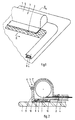
- Figure 1 is a schematic, perspective view of a part of a panel intended for use in an open roof construction according to the invention, on which a winding mechanism comprising a housing and guides is mounted;
- Figure 2 is a larger-scale sectional view along line II-II in Figure 1.
- a roof opening is formed in the roof of the vehicle, which roof opening can be closed and at least partially be released by a movable panel 1.
- the manner in which the roof opening has been formed in the roof of the vehicle and the manner in which the panel is movably mounted in the said roof opening do not fall within the framework of the present invention, and consequently they will not be discussed herein.
- the open roof construction comprises a sun screen device, which comprises at least a flexible cloth 2 which can be moved forward and backward in a direction substantially parallel to the roof opening, a winding mechanism 3 for winding and unwinding said cloth and guides 4 for guiding the side edges of cloth 2.
- winding mechanism 3 and the guides are mounted on panel 1, close to the circumferential edges thereof.
- winding mechanism 3 and the guides 4 are connected to the panel 1 in such a manner that an integral connection is formed between said elements.
- integral connection is understood to mean a connection which extends substantially continuously, usually along substantially the entire length of winding mechanism 3 and guides 4, between said winding mechanism and said guides and panel 1.
- the winding mechanism 3 comprises a housing consisting of a first (lower) part 5' and a second (upper) part 5' '.
- First part 5' is integrally connected to panel 1, whilst second part 5' ' is capable of pivoting movement with respect to first part 5' about a pivot 6. This makes it possible to either enclose a winding drum 7 disposed within housing 5 or make it accessible.
- pivot 6 may also be comprised of a weakened part of the material, thus forming a so-called “live pivot”.
- Locking means that may be used for retaining housing 5 in the illustrated position are not shown in the figures.
- the pivoted joint allows detachment of the housing parts 5' and 5' ' from each other.
- first part 5' On its side facing towards panel 1, first part 5' includes a recess 8, in which a glue 9 is present.
- the integral connection with the panel 1 is formed by means of said glue 9.
- the recess 8 containing the glue 9 forms a joint surface, as it were, which functions to form an adhesive connection with panel 1.
- edges 10 of recess 8 prevent the glue 9 from flowing out in an uncontrolled manner during mounting, whilst on the other hand they can function as positioning aids (possibly in combination with stops (not shown) on panel 1).
- guide 4 is likewise provided with a corresponding recess 8 for containing a glue.
- housing 5 and guides 4 are integrally connected to panel 1 in the above-described manner, they form stiffenings for the edges of panel 1, so that said panel will have a high local bending strength at that location. This obviates the need to locally provide separate stiffenings, thus making it possible to reduce the local thickness of the panel.
- housing 5 and guide 4 adjoin each other in the illustrated embodiment, so that an optimum guidance of the edges of cloth 2 is obtained. Furthermore it is possible to prevent the ingress of dirt into the guides and into the winding mechanism in this manner.
- housing 5 of winding mechanism 3 may, for example, comprise a U-shaped leg, which is slid over the edge of the panel, and which is tensioned in such a manner by means of suitable fixing elements that the clamped connection extends along the entire length of the housing 5.
- Such a construction can be used for guides 4 as well. This makes is easier to remove said parts.
Landscapes
- Engineering & Computer Science (AREA)
- Mechanical Engineering (AREA)
- Tents Or Canopies (AREA)
- Operating, Guiding And Securing Of Roll- Type Closing Members (AREA)
Abstract
Description
- The invention relates to an open roof construction for a vehicle, comprising a roof opening formed in the roof of the vehicle and a movable panel intended for closing and at least partially releasing the roof opening, wherein a sun screen device is disposed under the plane of the roof opening, which sun screen device comprises at least a flexible cloth, which can be moved forward and backward in a direction substantially parallel to the roof opening, a winding mechanism for winding and unwinding said cloth, and guides for the side edges of the cloth.
- In a first type of prior art open roof constructions of this kind, the winding mechanism and the guides are connected directly or indirectly to the edge of the roof opening. A construction of that kind has a number of drawbacks, however. It is necessary to use different winding mechanisms and/or guides for different open roof constructions, so that different constructions are required at the aforesaid edges of the roof opening. This stands in the way in particular of using a universal roof liner. Furthermore, the winding mechanism and the guides of such prior art open roof constructions prevent the roof liner from extending as far as the panel.
- In addition to that, there are also open roof constructions wherein the winding mechanism and/or at least part of the guides is (are) mounted on the panel. It is a drawback thereby that this construction, in combination with the stiffenings that are generally used at the panel edges, leads to a large panel thickness.
- The object of the invention is to provide an open roof construction of the present type, wherein the aforesaid drawbacks are eliminated in a simple yet efficient manner.
- In order to accomplish that objective, the open roof construction according to the invention is characterized in that said winding mechanism and said cloth guides are integrally connected to the panel.
- Within the framework of the present invention, the term "integral" is understood to mean that the winding mechanism and the guides, once they are connected to the panel, are in one piece therewith, as it were, with a continuous joint being present therebetween. This in contrast to constructions wherein the winding mechanism and/or at least part of the cloth guides are locally connected to the panel by means of discrete fixing elements.
- Numerous advantages are obtained with the open roof construction according to the invention. Since the winding mechanism and the guides now form part of the panel, it is possible to use an identical roof liner for a large number of different open roof constructions, which has a significant cost-saving effect. Moreover, the roof liner can now extend as far as the panel. Owing to the integral connection between the panel on the one hand and the winding mechanism and the guides on the other hand, said winding mechanism and said guides furthermore perform a stiffening function in addition to their specific function in the sun screen device. The winding mechanism and the guides stiffen the panel edges in such a manner that the panel will locally exhibit great bending strength. So far, it has been necessary to provide separate stiffenings at the panel edges in order to obtain such great local bending strength. Since the winding mechanism and the guides now perform a double function, it is possible to minimize the local thickness (overall height) of the panel.
- By connecting the winding mechanism and the guides to the panel, said winding mechanism and said guides will also move along with the panel, so that the opening of the panel has no influence whatsoever on the stability of the cloth. Another effect that is achieved therewith is the fact that the effect of the passing air flow on the cloth in the open position of the panel is reduced, so that said cloth will be soiled or damaged less easily.
- In one preferred embodiment of the open roof construction according to the invention, the winding mechanism and the guides include a joint surface on the side that faces towards the panel, which functions to provide an adhesive connection with the panel.
- Said joint surface makes it possible to effect the integral connection with the panel that extends continuously over a relatively large area, and which consequently provides a highly stable connection between the winding mechanism and the guides on the one hand and the panel on the other hand.
- In a convenient embodiment, said adhesive connection is a glued joint in that case.
- In this manner the connection, which extends over a continuous area, can be provided in a simple manner. In addition, such a glued joint provides great freedom of placement during mounting. Furthermore, an aesthetically attractive appearance (without unsightly attachments) is obtained in this manner.
- In principle, such a glued joint is permanent. If a non-permanent connection is to be formed, well-known clamped connections or the like may be used, wherein the clamped connection between the winding mechanism and the guides on the one hand and the panel on the other hand extends continuously along the entire length of said winding mechanism and said guides. This is understood to mean that it is possible per se to use discrete clamping members, which provide a continuous clamping action along the length of the winding mechanism and the guides, however.
- If a glued joint is used, it is advantageous from a constructional viewpoint if the joint surface is recessed for the purpose of containing a glue therein.
- On the one hand, such a recess contains the glue, whereby the edges prevent the glue from flowing out in lateral direction. In addition, the edges of the recess ensure that the parts in question (the winding mechanism and the guides) are exactly positioned with respect to the panel. It can even be considered thereby to have the recess (or the edges thereof) mate with stops or the like (to facilitate mounting) on the panel in order to determine the positions of the winding mechanism or the guides and the panel with respect to each other.
- Furthermore, in a special variant of an embodiment of the open roof construction according to the invention, the winding mechanism comprises a housing which accommodates a winding drum, said housing comprising a first part, which is integrally connected with the panel, and a second part, which is capable of pivoting movement with respect to said first part, between a position in which it encloses said winding drum and a position in which it provides access to said winding drum, for example for maintenance or replacement. If the winding shaft is accommodated in a housing according to the proposed embodiment, access to the winding shaft can readily be gained owing to the pivoted construction of the housing. Of course provisions may have been made for locking the housing securely in the closed position (in which it encloses the winding shaft).
- In a final embodiment of the open roof construction according to the invention, said housing and said guides adjoin each other.
- As a result of this construction, the edges of the cloth are retained in an effective manner along their entire length, as a result of which flapping of the cloth edges is prevented in a reliable manner. Furthermore it is possible in this manner to minimize the ingress of dirt into the guides or into the winding mechanism. In addition to this, this construction further contributes to obtaining an aesthetically attractive appearance.
- The invention will now be explained in more detail with reference to the drawing, which shows an embodiment of the open roof construction according to the invention.
- Figure 1 is a schematic, perspective view of a part of a panel intended for use in an open roof construction according to the invention, on which a winding mechanism comprising a housing and guides is mounted; and
- Figure 2 is a larger-scale sectional view along line II-II in Figure 1.
- In an open roof construction for a vehicle to which the invention relates, a roof opening is formed in the roof of the vehicle, which roof opening can be closed and at least partially be released by a
movable panel 1. The manner in which the roof opening has been formed in the roof of the vehicle and the manner in which the panel is movably mounted in the said roof opening do not fall within the framework of the present invention, and consequently they will not be discussed herein. Important is only the fact that the open roof construction comprises a sun screen device, which comprises at least aflexible cloth 2 which can be moved forward and backward in a direction substantially parallel to the roof opening, awinding mechanism 3 for winding and unwinding said cloth andguides 4 for guiding the side edges ofcloth 2. - As is apparent from Figure 1, the winding mechanism and the guides are mounted on
panel 1, close to the circumferential edges thereof.winding mechanism 3 and theguides 4 are connected to thepanel 1 in such a manner that an integral connection is formed between said elements. The term integral connection is understood to mean a connection which extends substantially continuously, usually along substantially the entire length ofwinding mechanism 3 andguides 4, between said winding mechanism and said guides andpanel 1. - As is shown in Figure 2, the
winding mechanism 3 comprises a housing consisting of a first (lower) part 5' and a second (upper) part 5' '. First part 5' is integrally connected topanel 1, whilst second part 5' ' is capable of pivoting movement with respect to first part 5' about apivot 6. This makes it possible to either enclose awinding drum 7 disposed withinhousing 5 or make it accessible. - Unlike the pivot which is shown in the illustrated embodiment,
pivot 6 may also be comprised of a weakened part of the material, thus forming a so-called "live pivot". Locking means that may be used for retaininghousing 5 in the illustrated position are not shown in the figures. Furthermore it is conceivable that the pivoted joint allows detachment of the housing parts 5' and 5' ' from each other. - On its side facing towards
panel 1, first part 5' includes arecess 8, in which aglue 9 is present. The integral connection with thepanel 1 is formed by means of saidglue 9. Therecess 8 containing theglue 9 forms a joint surface, as it were, which functions to form an adhesive connection withpanel 1. - On the one hand, the
edges 10 ofrecess 8 prevent theglue 9 from flowing out in an uncontrolled manner during mounting, whilst on the other hand they can function as positioning aids (possibly in combination with stops (not shown) on panel 1). - As is shown in Figure 1,
guide 4 is likewise provided with acorresponding recess 8 for containing a glue. - If
housing 5 andguides 4 are integrally connected topanel 1 in the above-described manner, they form stiffenings for the edges ofpanel 1, so that said panel will have a high local bending strength at that location. This obviates the need to locally provide separate stiffenings, thus making it possible to reduce the local thickness of the panel. - As is furthermore apparent from Figure 1,
housing 5 andguide 4 adjoin each other in the illustrated embodiment, so that an optimum guidance of the edges ofcloth 2 is obtained. Furthermore it is possible to prevent the ingress of dirt into the guides and into the winding mechanism in this manner. - Instead of a glued joint 9, also other joining methods may be considered. Thus,
housing 5 of windingmechanism 3 may, for example, comprise a U-shaped leg, which is slid over the edge of the panel, and which is tensioned in such a manner by means of suitable fixing elements that the clamped connection extends along the entire length of thehousing 5. Such a construction can be used forguides 4 as well. This makes is easier to remove said parts. - The invention is not restricted to the embodiments as described above and shown in the drawings, which can be varied in several ways without departing from the scope of the invention as defined in the claims.
Claims (6)
- An open roof construction for a vehicle, comprising a roof opening formed in the roof of the vehicle and a movable panel intended for closing and at least partially releasing the roof opening, wherein a sun screen device is disposed under the plane of the roof opening, which sun screen device comprises at least a flexible cloth, which can be moved forward and backward in a direction substantially parallel to the roof opening, a winding mechanism for winding and unwinding said cloth, and guides for the side edges of the cloth, characterized in that said winding mechanism and said cloth guides are integrally connected with the panel.
- An open roof construction according to claim 1, characterized in that the winding mechanism and the guides include a joint surface on the side that faces towards the panel, which functions to provide an adhesive connection with the panel.
- An open roof construction according to claim 2, characterized in that said adhesive connection is a glued joint.
- An open roof construction according to claim 3, characterized in that the joint surface is recessed for the purpose of containing a glue therein.
- An open roof construction according to any one of the preceding claims, characterized in that the winding mechanism comprises a housing which accommodates a winding drum, said housing comprising a first part, which is integrally connected with the panel, and a second part, which is capable of pivoting movement with respect to said first part, between a position in which it encloses said winding drum and a position in which it provides access to said winding drum
- An open roof construction according to claim 5, characterized in that said housing and said guides adjoin each other.
Applications Claiming Priority (2)
| Application Number | Priority Date | Filing Date | Title |
|---|---|---|---|
| NL1014933A NL1014933C2 (en) | 2000-04-13 | 2000-04-13 | Open roof construction for a vehicle. |
| NL1014933 | 2000-04-13 |
Publications (2)
| Publication Number | Publication Date |
|---|---|
| EP1145886A1 true EP1145886A1 (en) | 2001-10-17 |
| EP1145886B1 EP1145886B1 (en) | 2006-09-27 |
Family
ID=19771206
Family Applications (1)
| Application Number | Title | Priority Date | Filing Date |
|---|---|---|---|
| EP20010201185 Expired - Lifetime EP1145886B1 (en) | 2000-04-13 | 2001-03-29 | Open roof construction for a vehicle |
Country Status (3)
| Country | Link |
|---|---|
| EP (1) | EP1145886B1 (en) |
| DE (1) | DE60123310T2 (en) |
| NL (1) | NL1014933C2 (en) |
Cited By (4)
| Publication number | Priority date | Publication date | Assignee | Title |
|---|---|---|---|---|
| EP1452364A1 (en) * | 2003-02-27 | 2004-09-01 | Inalfa Roof Systems Group B.V. | Sunshade for an open roof construction |
| FR2925103A1 (en) * | 2007-12-17 | 2009-06-19 | Peugeot Citroen Automobiles Sa | Occultation function producing module for glass or window in roof of e.g. car, has lining element externally covering support and occultation device in partial manner, and connecting unit provided between lining element and support |
| WO2012121443A1 (en) * | 2011-03-10 | 2012-09-13 | (주)베바스토동희 홀딩스 | Roll blind for vehicles |
| US12024001B2 (en) | 2019-08-27 | 2024-07-02 | Inalfa Roof Systems Group B.V. | Sunshade system and method of manufacturing parts thereof |
Citations (2)
| Publication number | Priority date | Publication date | Assignee | Title |
|---|---|---|---|---|
| US5344206A (en) * | 1993-09-22 | 1994-09-06 | Middleton Roy J | Automobile shades |
| DE19538551C1 (en) * | 1995-10-17 | 1996-10-24 | Webasto Systemkomponenten Gmbh | Sun screen for motor vehicle sun-roof |
-
2000
- 2000-04-13 NL NL1014933A patent/NL1014933C2/en not_active IP Right Cessation
-
2001
- 2001-03-29 EP EP20010201185 patent/EP1145886B1/en not_active Expired - Lifetime
- 2001-03-29 DE DE2001623310 patent/DE60123310T2/en not_active Expired - Lifetime
Patent Citations (2)
| Publication number | Priority date | Publication date | Assignee | Title |
|---|---|---|---|---|
| US5344206A (en) * | 1993-09-22 | 1994-09-06 | Middleton Roy J | Automobile shades |
| DE19538551C1 (en) * | 1995-10-17 | 1996-10-24 | Webasto Systemkomponenten Gmbh | Sun screen for motor vehicle sun-roof |
Cited By (6)
| Publication number | Priority date | Publication date | Assignee | Title |
|---|---|---|---|---|
| EP1452364A1 (en) * | 2003-02-27 | 2004-09-01 | Inalfa Roof Systems Group B.V. | Sunshade for an open roof construction |
| US6957850B2 (en) | 2003-02-27 | 2005-10-25 | Inalfa Roof Systems Group B.V. | Sunshade assembly for use in an open roof construction and open roof construction provided with such a sunshade assembly |
| FR2925103A1 (en) * | 2007-12-17 | 2009-06-19 | Peugeot Citroen Automobiles Sa | Occultation function producing module for glass or window in roof of e.g. car, has lining element externally covering support and occultation device in partial manner, and connecting unit provided between lining element and support |
| WO2012121443A1 (en) * | 2011-03-10 | 2012-09-13 | (주)베바스토동희 홀딩스 | Roll blind for vehicles |
| US8955903B2 (en) | 2011-03-10 | 2015-02-17 | Webasto Donghee Holdings Co., Ltd. | Roll blind for vehicles |
| US12024001B2 (en) | 2019-08-27 | 2024-07-02 | Inalfa Roof Systems Group B.V. | Sunshade system and method of manufacturing parts thereof |
Also Published As
| Publication number | Publication date |
|---|---|
| NL1014933C2 (en) | 2001-10-16 |
| EP1145886B1 (en) | 2006-09-27 |
| DE60123310D1 (en) | 2006-11-09 |
| DE60123310T2 (en) | 2007-04-05 |
Similar Documents
| Publication | Publication Date | Title |
|---|---|---|
| US20040130189A1 (en) | Retractable roof for vehicles | |
| EP1486367B1 (en) | Open roof construction for a vehicle, and a vehicle having such open roof construction | |
| US5738402A (en) | Folding top for vehicles | |
| JP2574469B2 (en) | A shield that shields the side gap of a sliding or sliding one-turn roof of an automobile | |
| US20050029833A1 (en) | Top for a convertible vehicle | |
| US20020092630A1 (en) | Roller shade for a transparent vehicle roof section | |
| US6866336B2 (en) | Wind deflector arrangement for a motor vehicle roof | |
| GB2208832A (en) | A frame assembly for a vehicle roof | |
| EP1145886B1 (en) | Open roof construction for a vehicle | |
| US8177294B2 (en) | Vehicle roof | |
| US7594689B2 (en) | Top for a convertible vehicle | |
| JPH04124514U (en) | Frame structure of sunroof device | |
| US4798410A (en) | Lifting sliding roof for vehicles | |
| JPH0441092B2 (en) | ||
| US5609387A (en) | Lining panel for a sliding roof for a vehicle | |
| JP2001328489A (en) | Upper body structure of vehicle | |
| US12005768B2 (en) | Deflector mechanism of sunroof device | |
| US12441166B2 (en) | Roof system | |
| JPH04262919A (en) | Vehicle roof | |
| JPH0920147A (en) | Frame structure of sunroof for automobile | |
| JPS6296133A (en) | Vehicle roof | |
| EP0530867A2 (en) | Motor vehicle having an open roof construction | |
| JP4318496B2 (en) | Cabin door structure | |
| EP0990544A1 (en) | Open roof construction for a vehicle | |
| JPS60163723A (en) | Openable roof construction of car |
Legal Events
| Date | Code | Title | Description |
|---|---|---|---|
| PUAI | Public reference made under article 153(3) epc to a published international application that has entered the european phase |
Free format text: ORIGINAL CODE: 0009012 |
|
| AK | Designated contracting states |
Kind code of ref document: A1 Designated state(s): AT BE CH CY DE DK ES FI FR GB GR IE IT LI LU MC NL PT SE TR Kind code of ref document: A1 Designated state(s): DE FR GB |
|
| AX | Request for extension of the european patent |
Free format text: AL;LT;LV;MK;RO;SI |
|
| 17P | Request for examination filed |
Effective date: 20020404 |
|
| AKX | Designation fees paid |
Free format text: DE FR GB |
|
| RAP1 | Party data changed (applicant data changed or rights of an application transferred) |
Owner name: INALFA ROOF SYSTEMS GROUP B.V. |
|
| GRAP | Despatch of communication of intention to grant a patent |
Free format text: ORIGINAL CODE: EPIDOSNIGR1 |
|
| GRAS | Grant fee paid |
Free format text: ORIGINAL CODE: EPIDOSNIGR3 |
|
| GRAA | (expected) grant |
Free format text: ORIGINAL CODE: 0009210 |
|
| AK | Designated contracting states |
Kind code of ref document: B1 Designated state(s): DE FR GB |
|
| REG | Reference to a national code |
Ref country code: GB Ref legal event code: FG4D |
|
| REF | Corresponds to: |
Ref document number: 60123310 Country of ref document: DE Date of ref document: 20061109 Kind code of ref document: P |
|
| ET | Fr: translation filed | ||
| PLBE | No opposition filed within time limit |
Free format text: ORIGINAL CODE: 0009261 |
|
| STAA | Information on the status of an ep patent application or granted ep patent |
Free format text: STATUS: NO OPPOSITION FILED WITHIN TIME LIMIT |
|
| 26N | No opposition filed |
Effective date: 20070628 |
|
| GBPC | Gb: european patent ceased through non-payment of renewal fee |
Effective date: 20070329 |
|
| PG25 | Lapsed in a contracting state [announced via postgrant information from national office to epo] |
Ref country code: GB Free format text: LAPSE BECAUSE OF NON-PAYMENT OF DUE FEES Effective date: 20070329 |
|
| REG | Reference to a national code |
Ref country code: FR Ref legal event code: PLFP Year of fee payment: 15 |
|
| PGFP | Annual fee paid to national office [announced via postgrant information from national office to epo] |
Ref country code: FR Payment date: 20150331 Year of fee payment: 15 |
|
| REG | Reference to a national code |
Ref country code: FR Ref legal event code: ST Effective date: 20161130 |
|
| PG25 | Lapsed in a contracting state [announced via postgrant information from national office to epo] |
Ref country code: FR Free format text: LAPSE BECAUSE OF NON-PAYMENT OF DUE FEES Effective date: 20160331 |
|
| PGFP | Annual fee paid to national office [announced via postgrant information from national office to epo] |
Ref country code: DE Payment date: 20200327 Year of fee payment: 20 |
|
| REG | Reference to a national code |
Ref country code: DE Ref legal event code: R071 Ref document number: 60123310 Country of ref document: DE |