EP1145828A2 - Method for producing composite structure and composite structure produced thereby - Google Patents
Method for producing composite structure and composite structure produced thereby Download PDFInfo
- Publication number
- EP1145828A2 EP1145828A2 EP01303507A EP01303507A EP1145828A2 EP 1145828 A2 EP1145828 A2 EP 1145828A2 EP 01303507 A EP01303507 A EP 01303507A EP 01303507 A EP01303507 A EP 01303507A EP 1145828 A2 EP1145828 A2 EP 1145828A2
- Authority
- EP
- European Patent Office
- Prior art keywords
- composite structure
- preformed
- producing
- composite
- assembly
- Prior art date
- Legal status (The legal status is an assumption and is not a legal conclusion. Google has not performed a legal analysis and makes no representation as to the accuracy of the status listed.)
- Granted
Links
- 239000002131 composite material Substances 0.000 title claims abstract description 67
- 238000004519 manufacturing process Methods 0.000 title claims abstract description 25
- 238000010438 heat treatment Methods 0.000 claims abstract description 19
- 238000000034 method Methods 0.000 claims abstract description 13
- 239000000463 material Substances 0.000 description 11
- 229920005989 resin Polymers 0.000 description 10
- 239000011347 resin Substances 0.000 description 10
- 229920001187 thermosetting polymer Polymers 0.000 description 8
- 229920005992 thermoplastic resin Polymers 0.000 description 6
- 229910052782 aluminium Inorganic materials 0.000 description 5
- XAGFODPZIPBFFR-UHFFFAOYSA-N aluminium Chemical compound [Al] XAGFODPZIPBFFR-UHFFFAOYSA-N 0.000 description 5
- 239000003351 stiffener Substances 0.000 description 4
- 229910000831 Steel Inorganic materials 0.000 description 3
- 239000004918 carbon fiber reinforced polymer Substances 0.000 description 3
- 230000000694 effects Effects 0.000 description 3
- 238000010030 laminating Methods 0.000 description 3
- 229910052751 metal Inorganic materials 0.000 description 3
- 239000002184 metal Substances 0.000 description 3
- 239000010959 steel Substances 0.000 description 3
- OKTJSMMVPCPJKN-UHFFFAOYSA-N Carbon Chemical compound [C] OKTJSMMVPCPJKN-UHFFFAOYSA-N 0.000 description 2
- 229920000049 Carbon (fiber) Polymers 0.000 description 2
- XEEYBQQBJWHFJM-UHFFFAOYSA-N Iron Chemical compound [Fe] XEEYBQQBJWHFJM-UHFFFAOYSA-N 0.000 description 2
- 239000004677 Nylon Substances 0.000 description 2
- 229920006231 aramid fiber Polymers 0.000 description 2
- 239000004917 carbon fiber Substances 0.000 description 2
- 238000007796 conventional method Methods 0.000 description 2
- 229920001971 elastomer Polymers 0.000 description 2
- 239000000806 elastomer Substances 0.000 description 2
- 239000003822 epoxy resin Substances 0.000 description 2
- 239000003365 glass fiber Substances 0.000 description 2
- 229910002804 graphite Inorganic materials 0.000 description 2
- 239000010439 graphite Substances 0.000 description 2
- 150000002739 metals Chemical class 0.000 description 2
- VNWKTOKETHGBQD-UHFFFAOYSA-N methane Chemical compound C VNWKTOKETHGBQD-UHFFFAOYSA-N 0.000 description 2
- 229920001778 nylon Polymers 0.000 description 2
- 229920000647 polyepoxide Polymers 0.000 description 2
- 239000012783 reinforcing fiber Substances 0.000 description 2
- 229920002379 silicone rubber Polymers 0.000 description 2
- 239000004945 silicone rubber Substances 0.000 description 2
- 229910001220 stainless steel Inorganic materials 0.000 description 2
- 239000010935 stainless steel Substances 0.000 description 2
- 239000002759 woven fabric Substances 0.000 description 2
- KXGFMDJXCMQABM-UHFFFAOYSA-N 2-methoxy-6-methylphenol Chemical compound [CH]OC1=CC=CC([CH])=C1O KXGFMDJXCMQABM-UHFFFAOYSA-N 0.000 description 1
- 239000000853 adhesive Substances 0.000 description 1
- 230000001070 adhesive effect Effects 0.000 description 1
- 239000004760 aramid Substances 0.000 description 1
- 229920003235 aromatic polyamide Polymers 0.000 description 1
- 230000015572 biosynthetic process Effects 0.000 description 1
- 239000003795 chemical substances by application Substances 0.000 description 1
- 238000013461 design Methods 0.000 description 1
- 230000004927 fusion Effects 0.000 description 1
- 229910052742 iron Inorganic materials 0.000 description 1
- 238000012986 modification Methods 0.000 description 1
- 230000004048 modification Effects 0.000 description 1
- 229920001568 phenolic resin Polymers 0.000 description 1
- 239000005011 phenolic resin Substances 0.000 description 1
- 239000004033 plastic Substances 0.000 description 1
- 229920003023 plastic Polymers 0.000 description 1
- 230000002265 prevention Effects 0.000 description 1
- 238000011160 research Methods 0.000 description 1
- 238000007789 sealing Methods 0.000 description 1
- 229910000679 solder Inorganic materials 0.000 description 1
Images




Classifications
-
- B—PERFORMING OPERATIONS; TRANSPORTING
- B29—WORKING OF PLASTICS; WORKING OF SUBSTANCES IN A PLASTIC STATE IN GENERAL
- B29C—SHAPING OR JOINING OF PLASTICS; SHAPING OF MATERIAL IN A PLASTIC STATE, NOT OTHERWISE PROVIDED FOR; AFTER-TREATMENT OF THE SHAPED PRODUCTS, e.g. REPAIRING
- B29C70/00—Shaping composites, i.e. plastics material comprising reinforcements, fillers or preformed parts, e.g. inserts
- B29C70/04—Shaping composites, i.e. plastics material comprising reinforcements, fillers or preformed parts, e.g. inserts comprising reinforcements only, e.g. self-reinforcing plastics
- B29C70/28—Shaping operations therefor
- B29C70/30—Shaping by lay-up, i.e. applying fibres, tape or broadsheet on a mould, former or core; Shaping by spray-up, i.e. spraying of fibres on a mould, former or core
- B29C70/34—Shaping by lay-up, i.e. applying fibres, tape or broadsheet on a mould, former or core; Shaping by spray-up, i.e. spraying of fibres on a mould, former or core and shaping or impregnating by compression, i.e. combined with compressing after the lay-up operation
- B29C70/342—Shaping by lay-up, i.e. applying fibres, tape or broadsheet on a mould, former or core; Shaping by spray-up, i.e. spraying of fibres on a mould, former or core and shaping or impregnating by compression, i.e. combined with compressing after the lay-up operation using isostatic pressure
-
- B—PERFORMING OPERATIONS; TRANSPORTING
- B29—WORKING OF PLASTICS; WORKING OF SUBSTANCES IN A PLASTIC STATE IN GENERAL
- B29D—PRODUCING PARTICULAR ARTICLES FROM PLASTICS OR FROM SUBSTANCES IN A PLASTIC STATE
- B29D99/00—Subject matter not provided for in other groups of this subclass
- B29D99/001—Producing wall or panel-like structures, e.g. for hulls, fuselages, or buildings
- B29D99/0014—Producing wall or panel-like structures, e.g. for hulls, fuselages, or buildings provided with ridges or ribs, e.g. joined ribs
-
- B—PERFORMING OPERATIONS; TRANSPORTING
- B29—WORKING OF PLASTICS; WORKING OF SUBSTANCES IN A PLASTIC STATE IN GENERAL
- B29L—INDEXING SCHEME ASSOCIATED WITH SUBCLASS B29C, RELATING TO PARTICULAR ARTICLES
- B29L2007/00—Flat articles, e.g. films or sheets
- B29L2007/002—Panels; Plates; Sheets
-
- Y—GENERAL TAGGING OF NEW TECHNOLOGICAL DEVELOPMENTS; GENERAL TAGGING OF CROSS-SECTIONAL TECHNOLOGIES SPANNING OVER SEVERAL SECTIONS OF THE IPC; TECHNICAL SUBJECTS COVERED BY FORMER USPC CROSS-REFERENCE ART COLLECTIONS [XRACs] AND DIGESTS
- Y02—TECHNOLOGIES OR APPLICATIONS FOR MITIGATION OR ADAPTATION AGAINST CLIMATE CHANGE
- Y02T—CLIMATE CHANGE MITIGATION TECHNOLOGIES RELATED TO TRANSPORTATION
- Y02T50/00—Aeronautics or air transport
- Y02T50/40—Weight reduction
Definitions
- the present invention relates to a method for producing a composite structure having a three-dimensionally curved portion and a cylindrical portion, and to a composite structure produced thereby.
- Composite prepregs are light in weight and high in strength, so that they have been widely used as a material for automobiles, ships, aircrafts, etc.
- Aircrafts using the composite prepreg generally contain a composite structure having a three-dimensionally curved portion and a cylindrical portion.
- Such a composite structure is usually composed of a honeycomb sandwich panel or a stiffened panel.
- the composite structures composed of a honeycomb sandwich panel are produced by the steps of: cutting a honeycomb material into a desired shape to obtain a honeycomb core; laminating the honeycomb core with skins made of a composite prepreg on a forming die in a sandwich form to prepare an assembly; and forming the assembly by heating under a pressure.
- the composite structures composed of a honeycomb sandwich panel can be produced by relatively simple processes with reduced production cost.
- such composite structures are often disadvantageous in that sufficient weight-reducing effect is not achieved.
- the composite structures composed of a stiffened panel are produced by the steps of: laminating skins and stiffeners (stringers and frames) each made of composite prepregs on a forming die to prepare an assembly; and forming the assembly by heating under a pressure using a pressure bag, etc.
- the stiffened panels particularly such that the skins and the stiffeners are integrally formed, are superior in weight-reducing effect to the honeycomb sandwich panels.
- the stiffeners are preformed and then integrated with the skins while using a jig on the die, thereby increasing production cost.
- the stiffened panels are used for the three-dimensionally curved portions, the production cost is remarkably increased.
- a method of the present invention for producing a composite structure having a three-dimensionally curved portion and a cylindrical portion comprises the steps of: (a) placing an outer skin made of a composite prepreg on a forming die; (b) mounting a honeycomb core on a portion of the outer skin that forms the three-dimensionally curved portion; (c) superimposing an inner skin made of a composite prepreg thereon; (d) arranging a preformed frame member and a preformed stringer member each made of a composite prepreg on a portion of the inner skin that forms the cylindrical portion to prepare an assembly; and (e) forming the assembly by heating under a pressure.
- the honeycomb sandwich panel is generally formed under a pressure of approximately 3 kg/cm 2
- the stiffened panel is generally formed under a pressure of approximately 6 kg/cm 2 .
- the stiffened panel is deteriorated in its quality.
- an edge portion of a honeycomb core contained in the honeycomb sandwich panel is often unable to withstand the pressure, resulting in deformation (crush) thereof.
- the above assembly is preferably formed by heating under a pressure while disposing an elastic plate and a press plate on a fin portion where the outer skin and the inner skin overlap each other, to prevent the crush of the honeycomb core.
- a fin portion having a width of 500 mm or more can sufficiently prevent the crush of the honeycomb core without the elastic plate and the press plate.
- the honeycomb sandwich panel and the stiffened panel can be formed at the same time under a pressure of approximately 6 kg/cm 2 without the crush of the honeycomb core and insufficient forming.
- the pressure is preferably 6 to 7 kg/cm 2 .
- a plurality of the preformed frame members may be linearly arranged at an interval on the portion of the inner skin that forms the cylindrical portion, one or more of the preformed stringer member passing through the interval and intersecting the preformed frame members.
- the assembly is formed by heating while using a forming jig comprising a combination of an elastic jig engageable with the intersection of the preformed frame members and the preformed stringer member, and rigid jigs attachable to the members in portions other than the intersection.
- the method of the present invention can be suitably used for producing an aircraft body. Further, a composite structure of the present invention is obtainable by the method.
- a method of the present invention for producing a composite structure having a three-dimensionally curved portion and a cylindrical portion comprises the steps of: (a) placing an outer skin made of a composite prepreg on a forming die; (b) mounting a honeycomb core on a portion of the outer skin that forms the three-dimensionally curved portion; (c) superimposing an inner skin made of a composite prepreg thereon; (d) arranging a preformed frame member and a preformed stringer member each made of a composite prepreg on a portion of the inner skin that forms the cylindrical portion to prepare an assembly; and (e) forming the assembly by heating under a pressure.
- a composite structure of the present invention is obtainable by this method. The present invention will be explained in detail below with reference to Figs. 1 to 8, by way of example only.
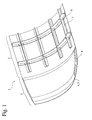
- Fig. 1 is a fragmentary perspective view showing an example of a composite structure according to the present invention.
- a composite structure 1 according to the present invention has a three-dimensionally curved portion 2 and a cylindrical portion 3.
- the three-dimensionally curved portion 2 is composed of a honeycomb sandwich panel containing a honeycomb core 6 between an outer skin 4 and an inner skin 5, and the cylindrical portion 3 is composed of a stiffened panel containing stringers 7 and frames 8.
- Each of the outer skin 4, the inner skin 5, the stringers 7 and the frames 8 is made of a composite prepreg.
- the shape of the three-dimensionally curved portion and the cylindrical portion is not limited by Fig. 1.
- the composite structure may have such a portion as a flat plate-shaped portion, etc. other than the three-dimensionally curved portion and the cylindrical portion, so that a complicated shaped portion is composed of the honeycomb sandwich panel and a simple shaped portion is composed of the stiffened panel in the present invention.
- Fig. 2 is a fragmentary sectional view showing an embodiment of the method for producing a composite structure according to the present invention.
- all elements are simply illustrated by straight lines, however, the present invention is not limited thereby.
- an outer skin 4 made of a composite prepreg is placed on a forming die, then, a honeycomb core 6 is mounted on a portion of the outer skin 4 that forms the three-dimensionally curved portion 2, and an inner skin 5 made of a composite prepreg is superimposed thereon.
- a preformed frame member 8a and a preformed stringer member (not shown in Fig. 2) each made of a composite prepreg is arranged on a portion of the inner skin 5 that forms the cylindrical portion 3 to prepare an assembly.
- three-dimensionally curved portion 2 and the cylindrical portion 3 of the assembly are concurrently formed by heating under a pressure to produce the composite structure.
- An adhesive may be applied between each of the elements if necessary, and a vacuum bag, a sealing agent, etc. may be used in forming.
- a thermosetting resin or a thermoplastic resin contained in the composite prepreg is fluidized by heating under pressure to integrally form the outer skin 4, the inner skin 5, the preformed frame member 8a and the preformed stringer member. It is particularly preferred that the assembly is formed by heating under a pressure while disposing an elastic plate 10 and a press plate 11 on a fin portion where the outer skin 4 and the inner skin 5 overlap each other as shown in Fig. 2. As a result, the slipping of the skins is suppressed by friction enhanced by the applied pressure and the edge effect of the press plate, to prevent the crush of the honeycomb core 6 even in the case of the high applied pressure, for example, 6 kg/cm 2 . Also, when the width L1 of the fin portion is 500 mm or more, the honeycomb core 6 is sufficiently prevented from crushing without the elastic plate 10 and the press plate 11.
- the forming pressure employed in the present invention is preferably 5 to 7 kg/cm 2 , more preferably 6 to 7 kg/cm 2 .
- the honeycomb sandwich panel and the stiffened panel can be concurrently formed under a higher pressure than that according to conventional methods where the honeycomb sandwich panel is formed under a pressure of usually 3 to 4 kg/cm 2 , resulting in no insufficient forming due to pressure shortage.
- the heating temperature may be selected depending on the kind of the thermosetting resin or the thermoplastic resin contained in the composite prepreg, the heating temperature is preferably 120 to 250 °C in general.
- the assembly may be formed by heating while using a forming jig.
- a plurality of the preformed frame members may be linearly arranged at an interval on the portion of the inner skin that forms the cylindrical portion, one or more of the preformed stringer member passing through the interval and intersecting the preformed frame members.
- the assembly is formed by heating while using a forming jig comprising a combination of an elastic jig engageable with the intersection of the preformed frame members and the preformed stringer member, and rigid jigs attachable to the members in portions other than the intersection.
- a forming jig makes it possible to integrally form the stiffened panel, particularly such that has a simple shape, at lower cost.
- the method for producing a composite structure according to the present invention is suited for the production of body structures of automobiles, vessels, aircrafts, etc., particularly aircraft bodies having a cabin corresponding to the above-mentioned cylindrical portion and a cockpit corresponding to the above-mentioned three-dimensionally curved portion.
- the cabin having a simple shape is composed of the integrally formed stiffened panel to reduce the weight of the aircraft body
- the cockpit is composed of the honeycomb sandwich panel to decrease production cost.
- the forming die used in the present invention may be made of a metal, a carbon fiber-reinforced plastic, etc.
- the forming die 9 may have a forming surface which the honeycomb core is mounted on, and an edge surface which the elastic plate 10 and the press plate 11 are disposed on.
- An angle ⁇ 1 between the forming surface and the edge surface is preferably 30 to 180°.
- the angle ⁇ 1 is particularly preferably 45 to 90° (60° in Fig. 3), to sufficiently prevent the skins from slipping even in the case where the widths L2 and L3 of the elastic plate 10 and the press plate 11 are made smaller.
- the outer skin and the inner skin are each made of such a composite prepreg that may be a woven fabric of a reinforcing fiber such as a carbon fiber, a glass fiber, an aramid fiber, etc., impregnated with a thermosetting resin or a thermoplastic resin.
- a thermosetting resin is an epoxy resin
- the thermoplastic resin is a nylon.
- the outer skin and the inner skin are preferably made of the same material, although they may be made of the different materials.
- the honeycomb core used in the present invention may be made of a paper, a paper impregnated with a resin, a plastic, aluminum, a steel, etc.
- a thermosetting resin having high specific strength is preferably used for the honeycomb core, and in this case, the thermosetting resin is preferably a phenolic resin.
- the honeycomb core preferably has a tapered portion provided by chamfering.
- the honeycomb core edge angle ⁇ 2 may be 30 to 90°, preferably 30 to 45° to sufficiently prevent the honeycomb core from crushing.
- the honeycomb core edge angle can be made larger than those in conventional methods, usually 30° or less, so that the tapered portion being a dead space can be made small, to design the composite structure in a various shape.
- preformed stringer member and the preformed frame member there is no particular limitation on the shape of the preformed stringer member and the preformed frame member, and they may be T-shaped as shown in Fig. 2, or C-shaped, J-shaped, etc. Further, the number and the positional relationship of the preformed stringer member and the preformed frame member arranged on the inner skin are also not particularly limited, may be such as shown in Fig. 4.
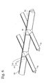
- preformed frame members 8b, 8c and 8d each having a base portion and a projecting portion are linearly arranged at an interval, and preformed stringer members 7a and 7b each having a base portion and a projecting portion pass through the interval and intersect the preformed frame members 8b, 8c and 8d.
- Each base portion of the preformed frame members 8b, 8c and 8d partially has a step.
- the preformed stringer member and the preformed frame member may be each preliminarily formed by laminating a plurality of composite prepregs, and by making a resin contained therein react or weld with each other.
- Each composite prepregs used for the preformed stringer member and the preformed frame member is preferably such a woven fabric of a reinforcing fiber such as a carbon fiber, a glass fiber, an aramid fiber, etc. that is impregnated with a thermosetting resin or a thermoplastic resin.
- the thermosetting resin is preferably an epoxy resin
- the thermoplastic resin is preferably a nylon.
- the preformed stringer member and the preformed frame member are preferably made of the same material, although they may be made of the different materials.
- the preformed stringer member, the preformed frame member, the outer skin and the inner skin are made of the same material.
- the preformed stringer member and the preformed frame member are preferably arranged on the inner skin in a semi-hardened state.
- the elastic plate and the press plate used in the present invention may have a simple flat plate shape, independently of the shape of the forming die. As shown in Fig. 5, even when the forming die 9 has a curved shape, the use of the elastic plate 10 allows the applied pressure to be uniformly transmitted to the skins, owing to the elasticity thereof.
- the width L2 of the elastic plate 10 and the width L3 of the press plate 11 may each be 40 mm or more for sufficient prevention of the crush of the honeycomb core and are preferably 40 to 250 mm for practical application.
- Each of the elastic plate and the press plate has a thickness of preferably 0.3 to 2 mm, more preferably 0.5 to 1 mm. When the thickness is less than 0.3 mm, the crush of the honeycomb core is not sufficiently prevented. On the other hand, when the thickness is more than 2 mm, the plates often do not match the shape of the forming die. Thus, the elastic plate and the press plate used in the present invention are very thin, so that they neither become obstacle in applying a vacuum bag nor break the vacuum bag.
- the elastic plate is preferably made of an elastomer having flexibility and heat resistance, more preferably made of a silicone rubber.
- the press plate is preferably made of a material excellent in strength and rigidity and low in thermal expansion.
- a material there can be mentioned metals such as a steel, a stainless steel and aluminum; graphite; carbon fiber-reinforced plastics, etc. Among them, aluminum is particularly preferred.
- Fig. 6 shows a state where the above-mentioned forming jig 12 comprising a combination of the elastic jigs 13 and the rigid jigs 14 is provided on the preformed stringer members 7a and 7b, and the preformed frame members 8b, 8c and 8d shown in Fig. 4.
- the elastic jigs 13 are engaged with the intersections of the preformed frame members 8b, 8c and 8d, and the preformed stringer members 7a and 7b.
- the rigid jigs 14 are attached to the members in portions other than the intersections.
- the elastic jig and the rigid jig is preferably used in combination with each other while compensating the disadvantages of each jig. That is, the elastic jig may be used at the intersection having a complicated shape to achieve high dimensional accuracy, while the rigid jigs fix the elastic jig at predetermined positions to achieve high positional accuracy.
- the elastic jig may have any shape as long as it can be used in combination with the rigid jigs and can be fitted to the intersection of the preformed stringer member and the preformed frame members.
- the width of the elastic jig in the direction of arrangement of the preformed frame member is preferably slightly larger in a free state than when combined with the rigid jigs for the formation of a composite structure.
- the width L4 of the elastic jig 13 before the forming operation shown in Fig. 7(a) is preferably larger than the width L5 of the elastic jig 13 after the forming operation shown in Fig.
- the elastic jig is preferably made of an elastomer having elasticity, heat resistance and releasability, more preferably made of a silicone rubber.
- the rigid jig is not critical in shape, it can be in any shape as long as it can maintain the positional accuracy of the composite structure in combination with the elastic jig.
- the rigid jig is preferably made of a material excellent in dimensional stability, strength and rigidity, and low in thermal expansion.
- a material there can be mentioned metals such as a steel, a stainless steel and aluminum; graphite; carbon fiber-reinforced plastics, etc.
- aluminum is particularly preferred.
- the forming jig mentioned above is preferably used together with two or more fixing means for fixing the preformed stringer member and/or the preformed frame member onto the inner skin.
- ends of the preformed frame members may be fixed to the inner skin 4 with fixing means 15 as shown in Fig. 8 (rigid jigs, etc. are not shown).
- the relative positional accuracy of the preformed stringer members and the preformed frame members is secured by using the combination of the elastic jig and the rigid jig, so that mere fixing of the members at ends with the fixing means can secure the entire positional accuracy without a large positioning jig, etc.
- the fixing mean may be fusion bonding by partial heating using a dryer, a low-temperature solder iron, etc., as well as a mechanical restricting mean such as a screw, a cramp, etc.
- a sufficiently lightweight composite structure having a three-dimensionally curved portion and a cylindrical portion can be produced with reduced production cost by simple processes comprising a step of forming a honeycomb sandwich panel and a stiffened panel at the same time. Further, the composite structure can be formed under such a high pressure as approximately 6 kg/cm 2 , thereby preventing insufficient forming due to pressure shortage.
- the method of the present invention is very useful for the production of the aircraft body.
Landscapes
- Engineering & Computer Science (AREA)
- Mechanical Engineering (AREA)
- Chemical & Material Sciences (AREA)
- Composite Materials (AREA)
- Architecture (AREA)
- Civil Engineering (AREA)
- Structural Engineering (AREA)
- Moulding By Coating Moulds (AREA)
- Casting Or Compression Moulding Of Plastics Or The Like (AREA)
Abstract
(a) placing an outer skin (4) made of a composite prepreg on a forming die; (b) mounting a honeycomb core (6) on a portion of the outer skin that forms the three-dimensionally curved portion; (c) superimposing an inner skin (5) made of a composite prepreg thereon; (d) arranging a preformed frame member (8a) and a preformed stringer member each made of a composite prepreg on a portion of the inner skin that forms the cylindrical portion to prepare an assembly; and (e) forming the assembly by heating under a pressure. A composite structure of the present invention can be produced by the method.
Description
As shown in Fig. 5, even when the forming
Claims (7)
- A method for producing a composite structure having a three-dimensionally curved portion (2) and a cylindrical portion (3), comprising the steps of:
(a) placing an outer skin (4) made of a composite prepreg on a forming die (9); (b) mounting a honeycomb core (6) on a portion of said outer skin that forms said three-dimensionally curved portion; (c) superimposing an inner skin (5) made of a composite prepreg thereon; (d) arranging a preformed frame member (8) and a preformed stringer member (7) each made of a composite prepreg on a portion of said inner skin that forms said cylindrical portion to prepare an assembly; and (e) forming said assembly by heating under a pressure. - The method for producing a composite structure according to claim 1, wherein said assembly is formed by heating under a pressure while disposing an elastic plate (10) and a press plate (11) on a fin portion where said outer skin (4) and said inner skin (5) overlap each other.
- The method for producing a composite structure according to claim 1 or 2, wherein said fin portion has a width of 500 mm or more.
- The method for producing a composite structure according to any one of claims 1 to 3, wherein said assembly is formed by heating under a pressure of 6 to 7 kg/cm2.
- The method for producing a composite structure according to any one of claims 1 to 4, wherein a plurality of said preformed frame members (8) are linearly arranged at an interval on said portion of said inner skin (5) that forms said cylindrical portion (3), one or more of said preformed stringer member (7) passing through said interval and intersecting said preformed frame members; and said assembly is formed by heating while using a forming jig (12) comprising a combination of an elastic jig (13) engageable with the intersection of said preformed frame members and said preformed stringer member, and rigid jigs (14) attachable to said preformed frame members and said preformed stringer member in portions other than said intersection.
- The method for producing a composite structure according to any one of claims 1 to 5, usable for producing an aircraft body.
- A composite structure obtainable by the method recited in any one of claims 1 to 6.
Applications Claiming Priority (2)
| Application Number | Priority Date | Filing Date | Title |
|---|---|---|---|
| JP2000113439 | 2000-04-14 | ||
| JP2000113439A JP4425422B2 (en) | 2000-04-14 | 2000-04-14 | Method for producing composite material structure and composite material structure produced thereby |
Publications (3)
| Publication Number | Publication Date |
|---|---|
| EP1145828A2 true EP1145828A2 (en) | 2001-10-17 |
| EP1145828A3 EP1145828A3 (en) | 2002-03-20 |
| EP1145828B1 EP1145828B1 (en) | 2003-09-24 |
Family
ID=18625401
Family Applications (1)
| Application Number | Title | Priority Date | Filing Date |
|---|---|---|---|
| EP01303507A Expired - Lifetime EP1145828B1 (en) | 2000-04-14 | 2001-04-17 | Method for producing composite structure and composite structure produced thereby |
Country Status (4)
| Country | Link |
|---|---|
| US (1) | US6802931B2 (en) |
| EP (1) | EP1145828B1 (en) |
| JP (1) | JP4425422B2 (en) |
| DE (1) | DE60100821T2 (en) |
Cited By (5)
| Publication number | Priority date | Publication date | Assignee | Title |
|---|---|---|---|---|
| EP1775106A1 (en) * | 2005-10-17 | 2007-04-18 | Saab Ab | Manufacturing method for a curved spar and other curved objects |
| WO2008090176A1 (en) * | 2007-01-23 | 2008-07-31 | Airbus Operations Gmbh | Shell element as part of an aircraft fuselage |
| CN103341987A (en) * | 2013-06-17 | 2013-10-09 | 沈阳飞机工业(集团)有限公司 | Co-curing process for omega-stringer vertical and horizontal reinforcement composite integral wallboard |
| EP2865516A1 (en) * | 2013-10-28 | 2015-04-29 | AIRBUS HELICOPTERS DEUTSCHLAND GmbH | Skin-stiffened composite panel and method of its manufacture |
| EP3272640A1 (en) | 2016-07-21 | 2018-01-24 | AIRBUS HELICOPTERS DEUTSCHLAND GmbH | A helicopter with a fuselage and a composite tail boom |
Families Citing this family (40)
| Publication number | Priority date | Publication date | Assignee | Title |
|---|---|---|---|---|
| JP4425424B2 (en) * | 2000-05-01 | 2010-03-03 | 本田技研工業株式会社 | Method for producing semi-cured article with joggle made of fiber reinforced composite material, and method for producing preformed structure using the same |
| JP2005231618A (en) * | 2004-01-23 | 2005-09-02 | Toray Ind Inc | Automotive outer panel |
| US7134629B2 (en) | 2004-04-06 | 2006-11-14 | The Boeing Company | Structural panels for use in aircraft fuselages and other structures |
| US7527222B2 (en) | 2004-04-06 | 2009-05-05 | The Boeing Company | Composite barrel sections for aircraft fuselages and other structures, and methods and systems for manufacturing such barrel sections |
| US7159822B2 (en) * | 2004-04-06 | 2007-01-09 | The Boeing Company | Structural panels for use in aircraft fuselages and other structures |
| US7325771B2 (en) | 2004-09-23 | 2008-02-05 | The Boeing Company | Splice joints for composite aircraft fuselages and other structures |
| US7503368B2 (en) | 2004-11-24 | 2009-03-17 | The Boeing Company | Composite sections for aircraft fuselages and other structures, and methods and systems for manufacturing such sections |
| US7332049B2 (en) * | 2004-12-22 | 2008-02-19 | General Electric Company | Method for fabricating reinforced composite materials |
| US7431978B2 (en) * | 2004-12-22 | 2008-10-07 | General Electric Company | Reinforced matrix composite containment duct |
| US7335012B2 (en) * | 2004-12-22 | 2008-02-26 | General Electric Company | Apparatus for fabricating reinforced composite materials |
| US8920594B2 (en) * | 2005-08-03 | 2014-12-30 | Sikorsky Aircraft Corporation | Composite thermoplastic matrix airframe structure and method of manufacture therefore |
| FR2906785B1 (en) * | 2006-10-10 | 2009-12-04 | Airbus France | AIRCRAFT FUSELAGE MADE FROM LONGITUDINAL PANELS AND METHOD FOR PRODUCING SUCH A FUSELAGE |
| US8388795B2 (en) | 2007-05-17 | 2013-03-05 | The Boeing Company | Nanotube-enhanced interlayers for composite structures |
| US8043458B2 (en) | 2007-06-21 | 2011-10-25 | Sikorsky Aircraft Corporation | Method of forming panels using an in-situ tape placement process and panels formed therefrom |
| ITMI20071448A1 (en) * | 2007-07-18 | 2009-01-19 | Alenia Aermacchi Spa | PROCEDURE FOR THE REALIZATION OF A SOUND ABSORBING PANEL FOR VEHICLES |
| US8042767B2 (en) | 2007-09-04 | 2011-10-25 | The Boeing Company | Composite fabric with rigid member structure |
| FR2928295B1 (en) * | 2008-03-07 | 2017-12-08 | Duqueine Rhone Alpes | METHOD AND DEVICE FOR MOLDING A CURVED PIECE OF COMPOSITE MATERIAL AND CORRESPONDING PIECE |
| DE102009013585B4 (en) | 2009-03-17 | 2012-01-26 | Airbus Operations Gmbh | Fuselage cell structure for a hybrid aircraft |
| CN102019592B (en) * | 2009-09-10 | 2012-07-04 | 中国航空工业集团公司北京航空制造工程研究所 | Positioning apparatus for shaping large-size stiffened panel made of composite material |
| US9121545B2 (en) | 2009-09-14 | 2015-09-01 | Bwdt, Llc | System for mounting objects to polymeric membranes |
| US8557070B2 (en) * | 2009-09-14 | 2013-10-15 | Joel A. Stanley | Method of mounting objects to polymeric membranes |
| US8623158B2 (en) | 2009-09-14 | 2014-01-07 | Joel A. Stanley | System for mounting objects to polymeric membranes |
| US8608884B2 (en) * | 2009-09-14 | 2013-12-17 | Joel A. Stanley | Method and system for mounting objects to polymeric membranes |
| US7935202B2 (en) * | 2009-09-14 | 2011-05-03 | Stanley Joel A | System for mounting objects to polymeric membranes |
| US9175479B2 (en) | 2009-09-14 | 2015-11-03 | Bwdt, Llc | System for mounting objects to polymeric membranes |
| US8499524B2 (en) * | 2009-09-14 | 2013-08-06 | Joel A. Stanley | System for mounting objects to polymeric membranes |
| US9121180B2 (en) * | 2009-09-14 | 2015-09-01 | Bwdt, Llc | System for mounting objects to polymeric membranes |
| DE102009057006A1 (en) * | 2009-12-04 | 2011-06-09 | Eads Deutschland Gmbh | Shell-like component e.g. carbon fiber reinforced shell, manufacturing device for aircraft body, has positioning body inserted into areas of struts and forming cross-section of cores, where semi-finished parts are supported on body |
| US8491743B2 (en) * | 2009-12-15 | 2013-07-23 | The Boeing Company | Composite ply stabilizing method |
| JP5550370B2 (en) * | 2010-02-05 | 2014-07-16 | 本田技研工業株式会社 | Method for manufacturing aircraft wing structure |
| CN101791821B (en) * | 2010-04-08 | 2011-09-14 | 中国航空工业集团公司北京航空制造工程研究所 | Forming equipment of large size composite stringer |
| CN103249542A (en) | 2010-07-13 | 2013-08-14 | 里尔喷射机公司 | Composite structures and methods of forming them |
| US20120199292A1 (en) * | 2011-02-03 | 2012-08-09 | Sikorsky Aircraft Corporation | Ply locking for honeycomb panels |
| GB2528080A (en) * | 2014-07-08 | 2016-01-13 | Airbus Operations Ltd | Structure |
| US11390045B2 (en) | 2018-09-07 | 2022-07-19 | Textron Innovations Inc. | Molding assembly and method of co-curing stiffener with panel |
| US11180238B2 (en) * | 2018-11-19 | 2021-11-23 | The Boeing Company | Shear ties for aircraft wing |
| US11981090B2 (en) * | 2019-07-19 | 2024-05-14 | The Boeing Company | Method of forming a reinforced panel component |
| CN113650196B (en) * | 2021-07-27 | 2023-04-14 | 中航西安飞机工业集团股份有限公司 | Accurate positioning device for T-shaped wet stringer forming die and using method |
| US12459717B2 (en) * | 2021-12-21 | 2025-11-04 | Gstc Llc | Container for transporting equipment for space-related applications |
| CN120533975A (en) * | 2025-06-19 | 2025-08-26 | 广东汇天航空航天科技有限公司 | Composite material component molding method, molded component, and aircraft |
Family Cites Families (12)
| Publication number | Priority date | Publication date | Assignee | Title |
|---|---|---|---|---|
| JPS5942621B2 (en) * | 1981-01-12 | 1984-10-16 | 富士重工業株式会社 | Method of manufacturing honeycomb sand german structure |
| US4416349A (en) | 1981-09-30 | 1983-11-22 | The Boeing Company | Viscoelastically damped reinforced skin structures |
| JPH058316A (en) * | 1991-07-05 | 1993-01-19 | Mitsubishi Heavy Ind Ltd | Method for manufacturing composite structure |
| US5242523A (en) | 1992-05-14 | 1993-09-07 | The Boeing Company | Caul and method for bonding and curing intricate composite structures |
| US5451377A (en) | 1993-09-29 | 1995-09-19 | Rockwell International Corp. | Composite structures and methods of manufacturing such structures |
| US5580502A (en) | 1995-03-23 | 1996-12-03 | Sikorsky Aircraft Corporation | Method of fabricating a composite article having an integral, co-cured composite stiffening member |
| FR2771330B1 (en) | 1997-11-26 | 2004-02-27 | Aerospatiale | METHOD OF MANUFACTURING A MONOLITHIC COMPOSITE PANEL ARTICULATED WITH INTEGRATED STRAIGHTENER MEANS, ARTICULATED PANEL OBTAINED AND ARTICULATED HOOD IN AN AIRCRAFT |
| GB9802597D0 (en) * | 1998-02-07 | 1998-04-01 | Hurel Dubois Uk Ltd | Panels and structures |
| KR100577669B1 (en) * | 1998-05-22 | 2006-05-09 | 사이텍 테크놀러지 코포레이션 | Core fracture prevention product and manufacturing method thereof |
| US6197146B1 (en) * | 1998-12-21 | 2001-03-06 | Sikorsky Aircraft Corporation | Method and apparatus for forming airfoil structures |
| JP4191343B2 (en) * | 1999-11-26 | 2008-12-03 | 本田技研工業株式会社 | Method for manufacturing honeycomb sandwich panel |
| US6523246B1 (en) * | 1999-11-26 | 2003-02-25 | Honda Giken Kogyo Kabushiki Kaisha | Jig used for formation of fiber-reinforced composite structure and method for formation of fiber-reinforced composite structure using jig |
-
2000
- 2000-04-14 JP JP2000113439A patent/JP4425422B2/en not_active Expired - Fee Related
-
2001
- 2001-04-12 US US09/832,794 patent/US6802931B2/en not_active Expired - Lifetime
- 2001-04-17 DE DE60100821T patent/DE60100821T2/en not_active Expired - Lifetime
- 2001-04-17 EP EP01303507A patent/EP1145828B1/en not_active Expired - Lifetime
Cited By (11)
| Publication number | Priority date | Publication date | Assignee | Title |
|---|---|---|---|---|
| EP1775106A1 (en) * | 2005-10-17 | 2007-04-18 | Saab Ab | Manufacturing method for a curved spar and other curved objects |
| US8871126B2 (en) | 2005-10-17 | 2014-10-28 | Saab Ab | Manufacturing method for trumpet spar and other curved objects |
| WO2008090176A1 (en) * | 2007-01-23 | 2008-07-31 | Airbus Operations Gmbh | Shell element as part of an aircraft fuselage |
| JP2010516539A (en) * | 2007-01-23 | 2010-05-20 | エアバス・オペレーションズ・ゲーエムベーハー | Aircraft body forming shell member |
| RU2466905C2 (en) * | 2007-01-23 | 2012-11-20 | Эйрбас Оператионс Гмбх | Skin element as aircraft fuselage part |
| CN103341987A (en) * | 2013-06-17 | 2013-10-09 | 沈阳飞机工业(集团)有限公司 | Co-curing process for omega-stringer vertical and horizontal reinforcement composite integral wallboard |
| CN103341987B (en) * | 2013-06-17 | 2015-09-09 | 沈阳飞机工业(集团)有限公司 | Ω long purlin orthogonal stiffeners composites wallboard co-curing reaction |
| EP2865516A1 (en) * | 2013-10-28 | 2015-04-29 | AIRBUS HELICOPTERS DEUTSCHLAND GmbH | Skin-stiffened composite panel and method of its manufacture |
| US9302446B2 (en) | 2013-10-28 | 2016-04-05 | Airbus Helicopters Deutschland GmbH | Skin-stiffened composite panel |
| EP3272640A1 (en) | 2016-07-21 | 2018-01-24 | AIRBUS HELICOPTERS DEUTSCHLAND GmbH | A helicopter with a fuselage and a composite tail boom |
| US10457373B2 (en) | 2016-07-21 | 2019-10-29 | Airbus Helicopters Deutschland GmbH | Aircraft with a fuselage and a composite tail boom |
Also Published As
| Publication number | Publication date |
|---|---|
| EP1145828A3 (en) | 2002-03-20 |
| US6802931B2 (en) | 2004-10-12 |
| DE60100821T2 (en) | 2004-04-08 |
| JP2001293738A (en) | 2001-10-23 |
| JP4425422B2 (en) | 2010-03-03 |
| EP1145828B1 (en) | 2003-09-24 |
| DE60100821D1 (en) | 2003-10-30 |
| US20010030380A1 (en) | 2001-10-18 |
Similar Documents
| Publication | Publication Date | Title |
|---|---|---|
| EP1145828B1 (en) | Method for producing composite structure and composite structure produced thereby | |
| US6551441B1 (en) | Method for producing honeycomb sandwich panel | |
| EP1149687B1 (en) | Method for producing body structure of fiber-reinforced composite, and body structure produced thereby | |
| US6689246B2 (en) | Method of making composite airfoil structures | |
| EP1750929B2 (en) | Structural panels for use in aircraft fuselages and other structures | |
| US8226870B2 (en) | Pressure bulkhead made of composite material for an aircraft | |
| CN102448814B (en) | Structure for assembly of the pressure bulkhead of an aircraft | |
| US6375120B1 (en) | Method and apparatus for building a metal/composite hybrid airplane component | |
| EP1089870B1 (en) | Reinforcement laminate | |
| US8490920B2 (en) | Composite bulkhead and skin construction | |
| US6706230B2 (en) | Auxiliary jig | |
| US20100025532A1 (en) | Shell element as part of an aircrfaft fuselage | |
| US20110308714A1 (en) | Method and shaping device for producing a composite fibre component for air and space travel | |
| US5849393A (en) | Structural element and method of making | |
| JP2015519222A (en) | Hat-type stiffener with inclined web and method for forming the same | |
| EP1800842A1 (en) | A method of manufacturing an elongate structural element configured for stiffening a shell structure, and a method for manufacturing a rigid shell structure integrated with at least one elongate stiffening element | |
| US6523246B1 (en) | Jig used for formation of fiber-reinforced composite structure and method for formation of fiber-reinforced composite structure using jig | |
| US8197625B2 (en) | Process of manufacturing composite structures with embedded precured tools | |
| JP2003034296A (en) | Window frame part structure of sailing machine body and method for assembling window frame part | |
| JPH07180281A (en) | Honeycomb sandwich panel and manufacture thereof | |
| US11560242B2 (en) | Method of manufacturing a structural part for a vehicle, in particular an aircraft or spacecraft | |
| US20020185777A1 (en) | Modular lay-up mold for a composite article and method of manufacture therefor | |
| JP3073178B2 (en) | Pillar structure for high-speed vehicles | |
| JPH1120687A (en) | Interior structure support structure for vehicle structure and its mounting method | |
| JP2008114633A (en) | Roof pillar integral molded member and roof pillar garnish integral molded member |
Legal Events
| Date | Code | Title | Description |
|---|---|---|---|
| PUAI | Public reference made under article 153(3) epc to a published international application that has entered the european phase |
Free format text: ORIGINAL CODE: 0009012 |
|
| AK | Designated contracting states |
Kind code of ref document: A2 Designated state(s): DE FR GB Kind code of ref document: A2 Designated state(s): AT BE CH CY DE DK ES FI FR GB GR IE IT LI LU MC NL PT SE TR |
|
| AX | Request for extension of the european patent |
Free format text: AL;LT;LV;MK;RO;SI |
|
| PUAL | Search report despatched |
Free format text: ORIGINAL CODE: 0009013 |
|
| AK | Designated contracting states |
Kind code of ref document: A3 Designated state(s): AT BE CH CY DE DK ES FI FR GB GR IE IT LI LU MC NL PT SE TR |
|
| AX | Request for extension of the european patent |
Free format text: AL;LT;LV;MK;RO;SI |
|
| 17P | Request for examination filed |
Effective date: 20020816 |
|
| AKX | Designation fees paid |
Free format text: DE FR GB |
|
| GRAH | Despatch of communication of intention to grant a patent |
Free format text: ORIGINAL CODE: EPIDOS IGRA |
|
| GRAH | Despatch of communication of intention to grant a patent |
Free format text: ORIGINAL CODE: EPIDOS IGRA |
|
| GRAA | (expected) grant |
Free format text: ORIGINAL CODE: 0009210 |
|
| AK | Designated contracting states |
Kind code of ref document: B1 Designated state(s): DE FR GB |
|
| REG | Reference to a national code |
Ref country code: GB Ref legal event code: FG4D |
|
| REG | Reference to a national code |
Ref country code: IE Ref legal event code: FG4D |
|
| REF | Corresponds to: |
Ref document number: 60100821 Country of ref document: DE Date of ref document: 20031030 Kind code of ref document: P |
|
| ET | Fr: translation filed | ||
| PLBE | No opposition filed within time limit |
Free format text: ORIGINAL CODE: 0009261 |
|
| STAA | Information on the status of an ep patent application or granted ep patent |
Free format text: STATUS: NO OPPOSITION FILED WITHIN TIME LIMIT |
|
| 26N | No opposition filed |
Effective date: 20040625 |
|
| REG | Reference to a national code |
Ref country code: IE Ref legal event code: MM4A |
|
| REG | Reference to a national code |
Ref country code: FR Ref legal event code: PLFP Year of fee payment: 16 |
|
| REG | Reference to a national code |
Ref country code: FR Ref legal event code: PLFP Year of fee payment: 17 |
|
| REG | Reference to a national code |
Ref country code: FR Ref legal event code: PLFP Year of fee payment: 18 |
|
| PGFP | Annual fee paid to national office [announced via postgrant information from national office to epo] |
Ref country code: FR Payment date: 20190313 Year of fee payment: 19 |
|
| PGFP | Annual fee paid to national office [announced via postgrant information from national office to epo] |
Ref country code: DE Payment date: 20190402 Year of fee payment: 19 |
|
| PGFP | Annual fee paid to national office [announced via postgrant information from national office to epo] |
Ref country code: GB Payment date: 20190417 Year of fee payment: 19 |
|
| REG | Reference to a national code |
Ref country code: DE Ref legal event code: R119 Ref document number: 60100821 Country of ref document: DE |
|
| PG25 | Lapsed in a contracting state [announced via postgrant information from national office to epo] |
Ref country code: DE Free format text: LAPSE BECAUSE OF NON-PAYMENT OF DUE FEES Effective date: 20201103 Ref country code: FR Free format text: LAPSE BECAUSE OF NON-PAYMENT OF DUE FEES Effective date: 20200430 |
|
| GBPC | Gb: european patent ceased through non-payment of renewal fee |
Effective date: 20200417 |
|
| PG25 | Lapsed in a contracting state [announced via postgrant information from national office to epo] |
Ref country code: GB Free format text: LAPSE BECAUSE OF NON-PAYMENT OF DUE FEES Effective date: 20200417 |