EP1145573B1 - Communication system with reduced power variation and method therefor - Google Patents
Communication system with reduced power variation and method therefor Download PDFInfo
- Publication number
- EP1145573B1 EP1145573B1 EP99934599A EP99934599A EP1145573B1 EP 1145573 B1 EP1145573 B1 EP 1145573B1 EP 99934599 A EP99934599 A EP 99934599A EP 99934599 A EP99934599 A EP 99934599A EP 1145573 B1 EP1145573 B1 EP 1145573B1
- Authority
- EP
- European Patent Office
- Prior art keywords
- power variation
- communication system
- symbols
- subchannel
- reduced power
- Prior art date
- Legal status (The legal status is an assumption and is not a legal conclusion. Google has not performed a legal analysis and makes no representation as to the accuracy of the status listed.)
- Expired - Lifetime
Links
Images

Classifications
-
- H—ELECTRICITY
- H04—ELECTRIC COMMUNICATION TECHNIQUE
- H04L—TRANSMISSION OF DIGITAL INFORMATION, e.g. TELEGRAPHIC COMMUNICATION
- H04L27/00—Modulated-carrier systems
- H04L27/32—Carrier systems characterised by combinations of two or more of the types covered by groups H04L27/02, H04L27/10, H04L27/18 or H04L27/26
- H04L27/34—Amplitude- and phase-modulated carrier systems, e.g. quadrature-amplitude modulated carrier systems
- H04L27/3405—Modifications of the signal space to increase the efficiency of transmission, e.g. reduction of the bit error rate, bandwidth, or average power
- H04L27/3416—Modifications of the signal space to increase the efficiency of transmission, e.g. reduction of the bit error rate, bandwidth, or average power in which the information is carried by both the individual signal points and the subset to which the individual points belong, e.g. using coset coding, lattice coding, or related schemes
-
- H—ELECTRICITY
- H04—ELECTRIC COMMUNICATION TECHNIQUE
- H04L—TRANSMISSION OF DIGITAL INFORMATION, e.g. TELEGRAPHIC COMMUNICATION
- H04L1/00—Arrangements for detecting or preventing errors in the information received
- H04L1/004—Arrangements for detecting or preventing errors in the information received by using forward error control
- H04L1/0041—Arrangements at the transmitter end
- H04L1/0043—Realisations of complexity reduction techniques, e.g. use of look-up tables
- H04L1/0044—Realisations of complexity reduction techniques, e.g. use of look-up tables specially adapted for power saving
-
- H—ELECTRICITY
- H04—ELECTRIC COMMUNICATION TECHNIQUE
- H04L—TRANSMISSION OF DIGITAL INFORMATION, e.g. TELEGRAPHIC COMMUNICATION
- H04L1/00—Arrangements for detecting or preventing errors in the information received
- H04L1/24—Testing correct operation
- H04L1/242—Testing correct operation by comparing a transmitted test signal with a locally generated replica
-
- H—ELECTRICITY
- H04—ELECTRIC COMMUNICATION TECHNIQUE
- H04L—TRANSMISSION OF DIGITAL INFORMATION, e.g. TELEGRAPHIC COMMUNICATION
- H04L27/00—Modulated-carrier systems
- H04L27/18—Phase-modulated carrier systems, i.e. using phase-shift keying
- H04L27/186—Phase-modulated carrier systems, i.e. using phase-shift keying in which the information is carried by both the individual signal points and the subset to which the individual signal points belong, e.g. coset coding or related schemes
-
- H—ELECTRICITY
- H04—ELECTRIC COMMUNICATION TECHNIQUE
- H04L—TRANSMISSION OF DIGITAL INFORMATION, e.g. TELEGRAPHIC COMMUNICATION
- H04L27/00—Modulated-carrier systems
- H04L27/26—Systems using multi-frequency codes
- H04L27/2601—Multicarrier modulation systems
- H04L27/2602—Signal structure
-
- H—ELECTRICITY
- H04—ELECTRIC COMMUNICATION TECHNIQUE
- H04L—TRANSMISSION OF DIGITAL INFORMATION, e.g. TELEGRAPHIC COMMUNICATION
- H04L27/00—Modulated-carrier systems
- H04L27/26—Systems using multi-frequency codes
- H04L27/2601—Multicarrier modulation systems
- H04L27/2614—Peak power aspects
- H04L27/2615—Reduction thereof using coding
-
- H—ELECTRICITY
- H04—ELECTRIC COMMUNICATION TECHNIQUE
- H04L—TRANSMISSION OF DIGITAL INFORMATION, e.g. TELEGRAPHIC COMMUNICATION
- H04L1/00—Arrangements for detecting or preventing errors in the information received
- H04L1/004—Arrangements for detecting or preventing errors in the information received by using forward error control
- H04L1/0056—Systems characterized by the type of code used
- H04L1/0059—Convolutional codes
- H04L1/006—Trellis-coded modulation
Definitions
- the present invention relates to a communication system with reduced power variation wherein data from a transmitter is transmitted to a receiver over a plurality of subchannels and a method therefor.
- the invention is applicable but not limited to a cellular communication system.
- each of the mobile stations communicate with typically a fixed base station. Communication from the mobile station to the base station is known as uplink and communication from the base station to the mobile station is known as downlink.
- the total coverage area of the system is divided into a number of separate cells each covered by a single base station.
- the cells are typically geographically distinct with an overlapping coverage area with neighbouring cells.
- the communication link will change from being between the mobile station and the base station of the first cell to being between the mobile station and the base station of the second cell. This is known as a handover. Specifically, some cells may lie completely within the coverage of other larger cells.
- All base stations are interconnected by a fixed network.
- This fixed network comprises communication lines, switches, interfaces to other communication networks and various controllers required for operating the network.
- a call from a mobile station is routed through the fixed network to the destination specific for this call. If the call is between two mobile stations of the same communication system the call will be routed through the fixed network to the base station of the cell in which the other mobile station currently is. A connection is thus established between the two serving cells through the fixed network.
- PSTN Public Switched Telephone Network
- the call is routed from the serving base station to the interface between the cellular mobile communication system and the PSTN. It is then routed from the interface to the telephone by the PSTN.
- PSTN Public Switched Telephone Network
- modulation methods are known for communication in cellular and other communication schemes. Some of these involve the transmission of data from a transmitter to a receiver over a plurality of distinct subchannels. Examples of this include Orthogonal Frequency Division Multiplex (OFDM) or multicode Code Division Multiple Access (CDMA) schemes.
- OFDM Orthogonal Frequency Division Multiplex
- CDMA multicode Code Division Multiple Access
- WO98/11698 describes and OFDM system where 'n' bit data words are encoded as 2 m symbol words, with the symbol words being generated to result in a desired low peak to average ratio.
- the document discloses introduction of error correction by increasing the size of the code word relative to the data word and transmitting the additional symbols over additional subchannels.
- the invention seeks to provide a system for reducing the peak to average of transmissions in a communication system using a subchannel modulation scheme.
- a communication system with reduced power variation wherein data is transmitted over a plurality of subchannels comprising at least one means of generating information symbols, a subchannel transmitter for transmission of channel symbols on individual subchannels in a combined signal, at least one encoder for encoding information symbols into higher order channel symbols at substantially the same symbol rate, the encoding both being in response to a forward error correction scheme and including selection between redundant symbol values to reduce power variation of the combined signal, and a subchannel receiver receiving the higher order channel symbols and regenerating the information symbols, characterized in that one channel symbol is generated for each information symbol.
- the average symbol energy of the channel symbols is substantially the same as the information symbols and the encoding of information symbols into higher order channel symbols is done independently for each subchannel.
- the forward error correcting scheme is a trellis coding scheme.
- the encoder comprises a first data input for the information symbols and at least a second data input for compensation data, the communication system further comprising means for generating compensation data reducing the amplitude variations of the combined signal.
- the communication scheme employed is an Orthogonal Frequency Division Multiplex (OFDM) subchannel communication scheme or a multicode Code Division Multiple Access (CDMA) subcharmel communication scheme.
- OFDM Orthogonal Frequency Division Multiplex
- CDMA Code Division Multiple Access
- a method of reducing power variation in a communication system wherein data is transmitted over a plurality of subchannels comprising generating information symbols, transmitting channel symbols on individual subchannels in a combined signal, encoding information symbols into higher order channel symbols at substantially the same symbol rate, the encoding both being in response to a forward error correction scheme and including selection between redundant symbol values to reduce power variation of the combined signal, and receiving the higher order channel symbols and regenerating the information symbols.
- the invention thus enables a reduction in the power variation of a subchannel transmitter without degrading performance or increasing transmission bandwidth by increasing the order of the channel symbols, introducing forward error correction coding and selecting between redundant symbol values so that power variation is minimised.
- FIG. 1 illustrates a cellular communication system 100.
- a base station 101 communicates with a number of mobile station 103 over radio channels 105.
- the base station 101 covers users within a certain geographical area 107 whereas other geographical areas 109, 111 are covered by other base stations 113, 115.
- each of the base stations 101, 113, 115 contain a broadcast carrier plus one or more traffic carriers.
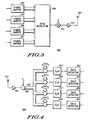
- FIG. 2 illustrates an example of a link between one mobile station 103 and one base station 101 using a subchannel modulation scheme.
- the data from a single data source 201 is separated into subchannels in a serial to parallel converter 203.
- the serial to parallel converter 203 is connected to a subchannel transmitter 205 which modulates the data, amplifies and transmits the modulated signal over the radio channel 209 by use of an antenna 207.
- the signal is received by a receive antenna 211 connected to a subchannel receiver 213 which regenerates the data transmitted on each individual subchannel.
- the data received in the subchannels are combined into a single data stream by a parallel to serial converter 215.
- FIG. 3 illustrates the principle of a 4 subchannel transmitter 300 using an OFDM modulation scheme.
- the data in each subchannel is fed to a symbol mapper 301-307 which maps the data into a complex symbol for transmission on the subchannel.
- Re(x) denotes the real part of x and rect(x) is given by
- the individual subchannels carrying the subchannel information is thus combined into a combined signal by the OFDM modulator.
- the combined signal is frequency shifted to the carrier frequency in a multiplier (or mixer) 311 and fed to the antenna 207 through an amplifier 313.
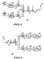
- FIG. 4 illustrates the principle of an OFDM subchannel receiver 400 for four subchannels.
- the signal from the receive antenna 211 is fed to a low noise amplifier 401 and the amplified signal is fed to a multiplier (or mixer) 403 down converting the signal to complex base band.
- the down-converted signal is fed to four complex multipliers and the output signal of each multiplier is fed to an integrator 413-419.
- the output signal on subchannel k is thus given by where r(t) is the down-converted received base band signal.
- r(t) is the down-converted received base band signal.
- the output of the integrators are fed to data detectors 421 - 427 which estimates the received symbol and maps it into the received data in the subchannel.
- OFDM modulation An overview' by W.Y.Zou and Y.Wu in IEEE Transactions on Broadcasting Vol. 41 No.1 pp 1-8, March 1995.
- FIG. 5 illustrates an example of a 2 channel subchannel transmitter 500 using a multicode CDMA subchannel modulation scheme.
- the input data in the two subchannels are mapped into complex symbols by the symbol mappers 501, 503.
- the complex symbols are multiplied by a first spreading code in multipliers 505, 507.
- the first spreading code is different for each subchannel and preferably the spreading codes are orthogonal between the channels.
- the two channels are added together in an adder 509 and the sum is in this example spread by multiplication in a second multiplier 511 by a common spreading code.
- the output of the multiplier is fed to a quadrature modulator 513 and the resultant signal is amplified in an amplifier 515 before being transmitted by the antenna 517.
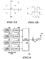
- FIG. 6 illustrates the principle of a multicode CDMA 2 channel subchannel receiver 600.
- the radio signal is received by an antenna 601 and amplified in a low noise amplifier 603.
- the output of the amplifier 603 is fed to a quadrature down converter which generates complex base band signal.
- This signal is de-spread by the common spreading code in a multiplier 607 before being fed to multipliers 609, 611 where the signal is de-spread with the spreading code in each subchannel.
- the output of the multipliers 609, 611 is fed to symbol time integrators 613,614.
- the signal for the other subchannel will for orthogonal spreading codes integrate to zero whereas the wanted signal following de-spreading will be restored to the non spread signal transmitted in this subchannel.
- the output of the integrators is fed to data detectors 617,619 which estimates the received symbol and generates the received data in the subchannel.
- CDMA communication systems can be found in ' Spread Spectrum CDMA Systems for Wireless Communications' by Savo Glisic and Branca Vucetic, Artech House, 1997, ISBN 0-89006-858-5 and in 'Multi-Carrier Spread Spectrum Modulation with Reduced Dynamic Range' by V.Aue and G.P.Fettweis, proceedings of IEEE 46th Vehicular Technology Conference, 1996, p914.
- the complex symbols transmitted will add up to a signal with varying amplitude as a consequence of the relative phase difference between the symbols.
- An example is given in FIG. 7 for a two channel CDMA transmitter using Quaternary Phase Shift Keying (QPSK).
- QPSK Quaternary Phase Shift Keying
- FIG. 7(a) illustrates the possible constellation points A, B, C, D for a QPSK symbol
- FIG. 7(b) illustrates an example of a short section of the spreading codes S 1 and S 2 for the two subchannels.
- the symbols constellation A is transmitted in both subchannels, the signals will add constructively during time interval T 1 and T 3 resulting in a summed signal corresponding to point E on FIG. 7(a).
- the two signals will have opposite phases due to the opposite signs of the spreading codes in this interval and the two signals will cancel out resulting in the constellation point F on FIG. 7(a).
- the amplitude variation of the transmitted signal is thus from 2 ⁇ 2 during time interval T 1 and T 3 to zero during T 2 .
- a high amplitude or power variation is disadvantageous in a transmitter as it requires a large dynamic range of linearity of the power amplifier. This significantly increases the complexity and cost of the amplifier and reduces the efficiency. Any non-linearity will furthermore distort the transmitted signal and increase the out of band transmission. The problems are enhanced in mobile stations where long battery life and low complexity amplifiers are required.
- the peak to average ratio of the transmit power level is reduced by mapping the information symbols into higher order channel symbols and selecting between redundant symbol values so that the power variation is reduced.
- the order of the symbols are increased to allow forward error correcting coding to compensate for reduction in the minimum distance between the symbols.
- 'information symbols' denotes the data symbols directly corresponding to the source data in the appropriate subchannel before any processing such as forward error correcting coding.
- 'Channel symbols' denote the symbols actually transmitted over the radio link and thus include any forward error correcting coding etc.
- a channel symbol being of higher order than an information symbol means that there are more constellation points of the symbol, such as for example a QPSK symbol being of higher order than a BPSK symbol.
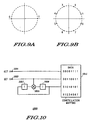
- FIG. 8 illustrates the embodiment for a 4 channel OFDM subchannel transmitter 800 corresponding to the one illustrated in FIG. 3.
- the symbol mappers 301-307 are in this case specifically BPSK symbol mappers 801-807.
- the output of the symbol mappers 801-807 are fed to encoders 809-815 which encode the information symbols into channel symbols by increasing the order of the symbols and using the increased redundancy to reduce power variation and include forward error correcting coding.
- the encoder will map the BPSK signal into 8 point Phase Shift Keying (8 PSK) using 2 bit trellis coding.
- FIG. 9 illustrates the constellation points for a BPSK symbol (FIG. 9(a)) and an 8-PSK symbol (FIG. 9(b)).
- FIG. 10 illustrates an example of a trellis coder 1000 which comprises two data inputs 1001,1003, the second input being fed to a binary multiplier 1005 which together with two delay elements 1007, 1009 generates a third binary value and introduces convolutional encoding.
- the three binary data values are fed to a data mapper 1011 which maps the data vector into the corresponding constellation point.
- the BPSK data from the symbol mappers 801-807 are fed to the second data input 1003 of the encoders 809-815.
- the mapping the data on the first data input 1001 shifts the channel symbol of the subchannel by 180°.
- the first data input 1001 is for each symbol and each encoder thus set to the value which for the current set of symbols across the sub-channels results in the lowest power variation with respect to the average power of the transmission.
- the determination of the appropriate compensation data to be applied to the first input 1001 of each encoder is preferably achieved by evaluating the power variation for all possible settings and choosing the one with the lowest variation.
- all possible settings of the data compensation vector are evaluated for all possible combinations of the information symbols on the subchannels. This evaluation can be carried out prior to operation and the preferred compensation data can be stored in a memory unit. The memory input will for every symbol be fed the information symbols of all subchannels and will generate the corresponding compensation data which is fed to the first data input 1001 of all encoders.
- the compensation data for the current symbol is determined in response not only to the current symbol but also to other symbols transmitted before or after the current symbol.
- the data transmitted in the entire burst is preferably considered when determining the compensation data for the information symbols of the burst.
- this is achieved by evaluating the power level variation over the burst for all possible data combinations in the burst and for all possible compensation data combinations prior to operation and the optimum choice of compensation data is stored in a memory unit.
- the set of data to be transmitted during the burst is fed to the memory unit, and the corresponding set of compensation data is obtained on the output of the memory unit.
- the receiver When receiving the transmitted signal, the receiver demodulates and decodes the trellis code as is known in the art. However, as the first data input 1001 does not carry any information but is solely used for reducing the power variation of the transmission, the corresponding bit can be ignored in the receiver.
- the symbol rate and thus bandwidth of the transmission does not increase by the trellis coding and power variation reduction.
- the energy per symbol of the information and channel symbols is preferably maintained identical.
- the uncoded symbol error is increased but this is compensated for by the trellis coding.
- the invention thus provides reduction of the peak to average power ratio without increasing the transmit power or bandwidth of the transmission.
- the forward error correcting coding is not done independently on each subchannel but is done by applying error correction to the set of data across the subchannels.
- the channel symbol in one subchannel will depend on the information symbols in other subchannels and not just on the information symbols in the current subchannel.
- the information symbols are encoded into 16 QAM (Quadrature Amplitude Modulation) using Trellis Coding.
- QAM Quadrature Amplitude Modulation
- This embodiment is suitable for the Universal Mobile Telecommunication System (UMTS) under standardisation by the European Telecommunication Standards Institute (ETSI).
- a Viterbi coder can be inserted between data source 201 and the serial to parallel converter 203 or can be connected to each subchannel output of the serial to parallel converter 203.
- a Viterbi decoder will be inserted at the output of the parallel to serial converter 215 or at each subchannel input to the parallel to serial converter 215 respectively.
- the compensation data is not simply ignored at the receiver but is demodulated and an estimate of the received redundant compensation data is derived.
- This estimate is used for evaluating a transmission quality preferably by evaluating the error probability of the received compensation data.
- a memory unit containing the pre-calculated compensation data for the current information symbols as used in the transmitter can be included in the receiver. After demodulation and decoding the received information symbols can be used as input for the memory unit in the receiver which will output the corresponding compensation data. This can be compared to the received compensation data and the difference between the two will indicate the error probability and thus the transmission quality.
- Each subchannel will typically have a specified transmission format associated with it and this may be predefined or adaptively modified according to the requirements and conditions of the communication system.
- the transmission format is different on different subchannels. For example, one subchannel may use 8PSK channel symbols for transmission of BPSK information symbols whereas another subchannel may simultaneously employ 16 QAM channel symbols for transmission of QPSK information symbols. Another example is where transmissions only occur on some subchannels whereas other subchannels have no transmissions.
- the encoding is performed independently on each subchannel in this embodiment.
- the power level of the transmissions in each subchannel may be different and the corresponding encoding can vary accordingly.
- the encoding for reduced power variation according to the current invention may be applied to these four subchannels only.
- the transmitted power of a mobile station will vary with the distance between the base station and the mobile station.
- the transmitted power will be close to the maximum and in order to ensure a high efficiency without distortion of the transmitted signal the power variations must be reduced to a minimum.
- a substantially lower power level is transmitted and the efficiency will not be significantly affected by power variations.
- the power amplifier will furthermore not be close to clipping or non-linear amplification and the distortion is thus reduced significantly.
- the technique for reducing power variations may only be applied to mobile stations close to the edges of the cells but not to mobile stations close to the base station and hence transmitting at low power.
- a more flexible approach is to alter the information and channel symbol transmission rates and thus the encoding algorithm according to the current conditions.
- the symbol mappers, encoders and the memory unit are preferably implemented in a suitable processor, such as a microprocessor or digital signal processor with associated memory, or is alternatively implemented in an integrated circuit.
- a suitable processor such as a microprocessor or digital signal processor with associated memory, or is alternatively implemented in an integrated circuit.
- the function performed by the symbol mappers, encoders and memory unit can be integrated in a single unit which generates the channel symbols in response to the data.
- the single unit may furthermore include the serial to parallel converter.
- the invention is applicable to cellular systems where the invention can be applied to only uplink transmissions, only downlink transmissions or to both uplink and downlink transmissions. It can furthermore be applied throughout the system or can be selectively employed for specific mobile stations or base stations.
Abstract
Description
- The present invention relates to a communication system with reduced power variation wherein data from a transmitter is transmitted to a receiver over a plurality of subchannels and a method therefor. The invention is applicable but not limited to a cellular communication system.
- In a cellular communication system each of the mobile stations communicate with typically a fixed base station. Communication from the mobile station to the base station is known as uplink and communication from the base station to the mobile station is known as downlink. The total coverage area of the system is divided into a number of separate cells each covered by a single base station. The cells are typically geographically distinct with an overlapping coverage area with neighbouring cells. As a mobile station moves from the coverage area of one cell to the coverage area of another cell, the communication link will change from being between the mobile station and the base station of the first cell to being between the mobile station and the base station of the second cell. This is known as a handover. Specifically, some cells may lie completely within the coverage of other larger cells.
- All base stations are interconnected by a fixed network. This fixed network comprises communication lines, switches, interfaces to other communication networks and various controllers required for operating the network. A call from a mobile station is routed through the fixed network to the destination specific for this call. If the call is between two mobile stations of the same communication system the call will be routed through the fixed network to the base station of the cell in which the other mobile station currently is. A connection is thus established between the two serving cells through the fixed network. Alternatively, if the call is between a mobile station and a telephone connected to the Public Switched Telephone Network (PSTN) the call is routed from the serving base station to the interface between the cellular mobile communication system and the PSTN. It is then routed from the interface to the telephone by the PSTN.
- Many different modulation methods are known for communication in cellular and other communication schemes. Some of these involve the transmission of data from a transmitter to a receiver over a plurality of distinct subchannels. Examples of this include Orthogonal Frequency Division Multiplex (OFDM) or multicode Code Division Multiple Access (CDMA) schemes. A common characteristic of these modulation schemes is that the transmitted power varies substantially dependent on the data in the subcharmels resulting in a high peak to average ratio of the transmitted power.
- A method of reducing this ratio is described in WO98/11698, which describes and OFDM system where 'n' bit data words are encoded as 2m symbol words, with the symbol words being generated to result in a desired low peak to average ratio. The document discloses introduction of error correction by increasing the size of the code word relative to the data word and transmitting the additional symbols over additional subchannels.
- In order to limit degradation and spectral spreading of the transmission, a high peak to average ratio of the transmit power requires that the output power amplifier has to be linear over a wide dynamic range. This significantly impairs the cost and efficiency of the power amplifier. This is especially a problem in mobile communication systems where a low efficiency of the output amplifier significantly reduces the battery life of the mobile station.
- Substantial benefits can thus be obtained by reducing the variations of the transmit power.
- The invention seeks to provide a system for reducing the peak to average of transmissions in a communication system using a subchannel modulation scheme.
- According to a first aspect of the invention, there is provided a communication system with reduced power variation wherein data is transmitted over a plurality of subchannels comprising at least one means of generating information symbols, a subchannel transmitter for transmission of channel symbols on individual subchannels in a combined signal, at least one encoder for encoding information symbols into higher order channel symbols at substantially the same symbol rate, the encoding both being in response to a forward error correction scheme and including selection between redundant symbol values to reduce power variation of the combined signal, and a subchannel receiver receiving the higher order channel symbols and regenerating the information symbols, characterized in that one channel symbol is generated for each information symbol.
- Preferably, the average symbol energy of the channel symbols is substantially the same as the information symbols and the encoding of information symbols into higher order channel symbols is done independently for each subchannel.
- According to a preferred feature of the invention the forward error correcting scheme is a trellis coding scheme.
- According to a second preferred feature of the invention, the encoder comprises a first data input for the information symbols and at least a second data input for compensation data, the communication system further comprising means for generating compensation data reducing the amplitude variations of the combined signal.
- Preferably, the communication scheme employed is an Orthogonal Frequency Division Multiplex (OFDM) subchannel communication scheme or a multicode Code Division Multiple Access (CDMA) subcharmel communication scheme.
- According to a second aspect of the invention, there is provided a method of reducing power variation in a communication system wherein data is transmitted over a plurality of subchannels, the method comprising generating information symbols, transmitting channel symbols on individual subchannels in a combined signal, encoding information symbols into higher order channel symbols at substantially the same symbol rate, the encoding both being in response to a forward error correction scheme and including selection between redundant symbol values to reduce power variation of the combined signal, and receiving the higher order channel symbols and regenerating the information symbols.
- The invention thus enables a reduction in the power variation of a subchannel transmitter without degrading performance or increasing transmission bandwidth by increasing the order of the channel symbols, introducing forward error correction coding and selecting between redundant symbol values so that power variation is minimised.
- An embodiment of the present invention is described below, by way of example only, with reference to the accompanying drawing, in which:
- FIG. 1 is an illustration of a cellular communication system according to prior art.
- FIG. 2 is a block diagram of an example of a single communication link between one mobile station and one base station using a subchannel modulation scheme using conventional means.
- FIG. 3 is a block diagram of a conventional 4 subchannel transmitter using an OFDM modulation scheme .
- FIG. 4 is a block diagram of a conventional
OFDM subchannel receiver 400 for four subchannels. - FIG. 5 is a block diagram of conventional 2 channel subchannel transmitter using a multicode CDMA subchannel modulation scheme.
- FIG. 6 is a block diagram of a
conventional multicode CDMA 2 channel subchannel receiver. - FIG. 7 is an illustration of the possible constellation points for a QPSK symbol and of a short section of the spreading codes for the two subchannels.
- FIG. 8 is a block diagram of a 4 channel OFDM subchannel transmitter in accordance to the invention.
- FIG. 9 is an illustration of the constellation points for a BPSK symbol and an 8-PSK symbol.
- FIG. 10 is an illustration of an example of a trellis coder.
-
- FIG. 1 illustrates a
cellular communication system 100. In the system, abase station 101 communicates with a number ofmobile station 103 overradio channels 105. In the cellular system, thebase station 101 covers users within a certaingeographical area 107 whereas othergeographical areas other base stations 113, 115. Typically, each of thebase stations - FIG. 2 illustrates an example of a link between one
mobile station 103 and onebase station 101 using a subchannel modulation scheme. In the example, the data from asingle data source 201 is separated into subchannels in a serial toparallel converter 203. Alternatively, the data on different subchannels may originate from different data sources. The serial toparallel converter 203 is connected to asubchannel transmitter 205 which modulates the data, amplifies and transmits the modulated signal over theradio channel 209 by use of anantenna 207. The signal is received by a receiveantenna 211 connected to asubchannel receiver 213 which regenerates the data transmitted on each individual subchannel. In the example, the data received in the subchannels are combined into a single data stream by a parallel toserial converter 215. - FIG. 3 illustrates the principle of a 4
subchannel transmitter 300 using an OFDM modulation scheme. The data in each subchannel is fed to a symbol mapper 301-307 which maps the data into a complex symbol for transmission on the subchannel. The complex symbols are fed to theOFDM modulator 309 which generates an OFDM modulated signal s(t) given bywhere di,k is data symbol i on subchannel k, fk the modulation frequency of subchannel k given by fk=k·f0 where f0 is the frequency of the subchannel with the lowest frequency. Re(x) denotes the real part of x and rect(x) is given by

- The individual subchannels carrying the subchannel information is thus combined into a combined signal by the OFDM modulator. The combined signal is frequency shifted to the carrier frequency in a multiplier (or mixer) 311 and fed to the
antenna 207 through anamplifier 313. - FIG. 4 illustrates the principle of an
OFDM subchannel receiver 400 for four subchannels. The signal from the receiveantenna 211 is fed to alow noise amplifier 401 and the amplified signal is fed to a multiplier (or mixer) 403 down converting the signal to complex base band. The down-converted signal is fed to four complex multipliers and the output signal of each multiplier is fed to an integrator 413-419. The output signal on subchannel k is thus given bywhere r(t) is the down-converted received base band signal. In each subchannel the integration over a symbol period will result in the signals from other subchannels cancelling out whereas the signal in the current subchannel is restored to an integration of the basic pulse shape, in this case given by the rect(x) function. The output of the integrators are fed to data detectors 421 - 427 which estimates the received symbol and maps it into the received data in the subchannel.
- A more detailed description of OFDM modulation can be found in 'COFDM modulation: an overview' by W.Y.Zou and Y.Wu in IEEE Transactions on Broadcasting Vol. 41 No.1 pp 1-8, March 1995.
- FIG. 5 illustrates an example of a 2
channel subchannel transmitter 500 using a multicode CDMA subchannel modulation scheme. The input data in the two subchannels are mapped into complex symbols by thesymbol mappers multipliers adder 509 and the sum is in this example spread by multiplication in asecond multiplier 511 by a common spreading code. The output of the multiplier is fed to aquadrature modulator 513 and the resultant signal is amplified in anamplifier 515 before being transmitted by theantenna 517. - FIG. 6 illustrates the principle of a
multicode CDMA 2channel subchannel receiver 600. The radio signal is received by anantenna 601 and amplified in alow noise amplifier 603. The output of theamplifier 603 is fed to a quadrature down converter which generates complex base band signal. This signal is de-spread by the common spreading code in amultiplier 607 before being fed tomultipliers multipliers - Further description of CDMA communication systems can be found in ' Spread Spectrum CDMA Systems for Wireless Communications' by Savo Glisic and Branca Vucetic, Artech House, 1997, ISBN 0-89006-858-5 and in 'Multi-Carrier Spread Spectrum Modulation with Reduced Dynamic Range' by V.Aue and G.P.Fettweis, proceedings of IEEE 46th Vehicular Technology Conference, 1996, p914.
- In both OFDM and CDMA subchannel transmitters, the complex symbols transmitted will add up to a signal with varying amplitude as a consequence of the relative phase difference between the symbols. An example is given in FIG. 7 for a two channel CDMA transmitter using Quaternary Phase Shift Keying (QPSK).
- FIG. 7(a) illustrates the possible constellation points A, B, C, D for a QPSK symbol and FIG. 7(b) illustrates an example of a short section of the spreading codes S1 and S2 for the two subchannels. Assuming the symbol constellation A is transmitted in both subchannels, the signals will add constructively during time interval T1 and T3 resulting in a summed signal corresponding to point E on FIG. 7(a). During time interval T2 the two signals will have opposite phases due to the opposite signs of the spreading codes in this interval and the two signals will cancel out resulting in the constellation point F on FIG. 7(a). The amplitude variation of the transmitted signal is thus from 2√2 during time interval T1 and T3 to zero during T2.
- If however symbol A is transmitted in the first subchannel and symbol B is transmitted in the second subchannel, the two channels will add together in point G during T1 and T3, and in point H during interval T2. The amplitude of both point G and H is 2 and there is thus no amplitude variation in this case.
- A high amplitude or power variation is disadvantageous in a transmitter as it requires a large dynamic range of linearity of the power amplifier. This significantly increases the complexity and cost of the amplifier and reduces the efficiency. Any non-linearity will furthermore distort the transmitted signal and increase the out of band transmission. The problems are enhanced in mobile stations where long battery life and low complexity amplifiers are required.
- According to an embodiment of the present invention, the peak to average ratio of the transmit power level is reduced by mapping the information symbols into higher order channel symbols and selecting between redundant symbol values so that the power variation is reduced. In addition, the order of the symbols are increased to allow forward error correcting coding to compensate for reduction in the minimum distance between the symbols.
- The term 'information symbols' denotes the data symbols directly corresponding to the source data in the appropriate subchannel before any processing such as forward error correcting coding. 'Channel symbols' denote the symbols actually transmitted over the radio link and thus include any forward error correcting coding etc. A channel symbol being of higher order than an information symbol means that there are more constellation points of the symbol, such as for example a QPSK symbol being of higher order than a BPSK symbol.
- The embodiment is described in more detail in the following for the specific example where the data to be transmitted on each subchannel is mapped into Binary Phase Shift Keying (BPSK) symbols. FIG. 8 illustrates the embodiment for a 4 channel
OFDM subchannel transmitter 800 corresponding to the one illustrated in FIG. 3. The symbol mappers 301-307 are in this case specifically BPSK symbol mappers 801-807. The output of the symbol mappers 801-807 are fed to encoders 809-815 which encode the information symbols into channel symbols by increasing the order of the symbols and using the increased redundancy to reduce power variation and include forward error correcting coding. - Preferably, the encoder will map the BPSK signal into 8 point Phase Shift Keying (8 PSK) using 2 bit trellis coding. FIG. 9 illustrates the constellation points for a BPSK symbol (FIG. 9(a)) and an 8-PSK symbol (FIG. 9(b)). FIG. 10 illustrates an example of a
trellis coder 1000 which comprises twodata inputs binary multiplier 1005 which together with twodelay elements data mapper 1011 which maps the data vector into the corresponding constellation point. A more detailed description of trellis coding can be found in 'Trellis-coded Modulation with Redundant Signal Sets Part 1: Introduction' by G. Ungerboeck in IEEE Communications Magazine, February 87 Vol 25No 2 or in ' Trellis Coding' by Christian Schlegel, IEEE Press 1997, ISBN 0-7803-1052-7. - The BPSK data from the symbol mappers 801-807 are fed to the
second data input 1003 of the encoders 809-815. As can be seen from the mapping the data on thefirst data input 1001 shifts the channel symbol of the subchannel by 180°. By setting thefirst data input 1001 of each encoder the channel symbols on each subchannel can thus be rotated with respect to each other to reduce the power variation. Thefirst data input 1001 is for each symbol and each encoder thus set to the value which for the current set of symbols across the sub-channels results in the lowest power variation with respect to the average power of the transmission. - The determination of the appropriate compensation data to be applied to the
first input 1001 of each encoder is preferably achieved by evaluating the power variation for all possible settings and choosing the one with the lowest variation. - According to one embodiment all possible settings of the data compensation vector are evaluated for all possible combinations of the information symbols on the subchannels. This evaluation can be carried out prior to operation and the preferred compensation data can be stored in a memory unit. The memory input will for every symbol be fed the information symbols of all subchannels and will generate the corresponding compensation data which is fed to the
first data input 1001 of all encoders. - Due to inter symbol interference the power level variation may not only depend on the channel symbols currently being transmitted but also on previously transmitted symbols. According to an alternative embodiment, the compensation data for the current symbol is determined in response not only to the current symbol but also to other symbols transmitted before or after the current symbol. Specifically, if transmission is of a bursty nature, the data transmitted in the entire burst is preferably considered when determining the compensation data for the information symbols of the burst. Preferably, this is achieved by evaluating the power level variation over the burst for all possible data combinations in the burst and for all possible compensation data combinations prior to operation and the optimum choice of compensation data is stored in a memory unit. During operation the set of data to be transmitted during the burst is fed to the memory unit, and the corresponding set of compensation data is obtained on the output of the memory unit.
- When receiving the transmitted signal, the receiver demodulates and decodes the trellis code as is known in the art. However, as the
first data input 1001 does not carry any information but is solely used for reducing the power variation of the transmission, the corresponding bit can be ignored in the receiver. - As one channel symbol is generated for each information symbol, the symbol rate and thus bandwidth of the transmission does not increase by the trellis coding and power variation reduction. Furthermore, the energy per symbol of the information and channel symbols is preferably maintained identical. As the minimum distance between constellation points is reduced, the uncoded symbol error is increased but this is compensated for by the trellis coding. The invention thus provides reduction of the peak to average power ratio without increasing the transmit power or bandwidth of the transmission.
- According to an alternative embodiment the forward error correcting coding is not done independently on each subchannel but is done by applying error correction to the set of data across the subchannels. In this embodiment the channel symbol in one subchannel will depend on the information symbols in other subchannels and not just on the information symbols in the current subchannel.
- In a different embodiment of the invention applicable to a subchannel CDMA transmitter with QPSK information symbols, the information symbols are encoded into 16 QAM (Quadrature Amplitude Modulation) using Trellis Coding. This results in similar performance as QPSK for the same transmission bandwidth and power, and provides a redundant bit for rotating each channel symbol permitting reduction in power level variations. This embodiment is suitable for the Universal Mobile Telecommunication System (UMTS) under standardisation by the European Telecommunication Standards Institute (ETSI).
- It will be apparent to the person skilled in the art that other error correcting schemes such as block coding or convolutional coding can be used instead of Trellis Coding.
- In addition to the forward error correcting coding introduced in the encoders, conventional forward error correcting coding can be applied to the data as is well known in the art. As a specific example referring to FIG. 2, a Viterbi coder can be inserted between
data source 201 and the serial toparallel converter 203 or can be connected to each subchannel output of the serial toparallel converter 203. At the receive side, a Viterbi decoder will be inserted at the output of the parallel toserial converter 215 or at each subchannel input to the parallel toserial converter 215 respectively. - According to a different embodiment the compensation data is not simply ignored at the receiver but is demodulated and an estimate of the received redundant compensation data is derived. This estimate is used for evaluating a transmission quality preferably by evaluating the error probability of the received compensation data. For example, a memory unit containing the pre-calculated compensation data for the current information symbols as used in the transmitter can be included in the receiver. After demodulation and decoding the received information symbols can be used as input for the memory unit in the receiver which will output the corresponding compensation data. This can be compared to the received compensation data and the difference between the two will indicate the error probability and thus the transmission quality.
- Each subchannel will typically have a specified transmission format associated with it and this may be predefined or adaptively modified according to the requirements and conditions of the communication system. According to one embodiment of the invention the transmission format is different on different subchannels. For example, one subchannel may use 8PSK channel symbols for transmission of BPSK information symbols whereas another subchannel may simultaneously employ 16 QAM channel symbols for transmission of QPSK information symbols. Another example is where transmissions only occur on some subchannels whereas other subchannels have no transmissions. Preferably, the encoding is performed independently on each subchannel in this embodiment.
- Alternatively or in addition the power level of the transmissions in each subchannel may be different and the corresponding encoding can vary accordingly. For example if four subchannels are transmitted at say twice the power level of four other subchannels, the encoding for reduced power variation according to the current invention may be applied to these four subchannels only.
- The encoding and application of the described technique can be dynamically altered to suit the current needs and conditions. Specifically, in a cellular communication system the transmitted power of a mobile station will vary with the distance between the base station and the mobile station. When the mobile station is far from the base station the transmitted power will be close to the maximum and in order to ensure a high efficiency without distortion of the transmitted signal the power variations must be reduced to a minimum. However, when the mobile station is close to the base station a substantially lower power level is transmitted and the efficiency will not be significantly affected by power variations. At the low power level the power amplifier will furthermore not be close to clipping or non-linear amplification and the distortion is thus reduced significantly.
- Accordingly, the technique for reducing power variations may only be applied to mobile stations close to the edges of the cells but not to mobile stations close to the base station and hence transmitting at low power. A more flexible approach is to alter the information and channel symbol transmission rates and thus the encoding algorithm according to the current conditions.
- The symbol mappers, encoders and the memory unit are preferably implemented in a suitable processor, such as a microprocessor or digital signal processor with associated memory, or is alternatively implemented in an integrated circuit.
- It will be apparent to the person skilled in the art that the function performed by the symbol mappers, encoders and memory unit can be integrated in a single unit which generates the channel symbols in response to the data. The single unit may furthermore include the serial to parallel converter.
- The invention is applicable to cellular systems where the invention can be applied to only uplink transmissions, only downlink transmissions or to both uplink and downlink transmissions. It can furthermore be applied throughout the system or can be selectively employed for specific mobile stations or base stations.
- It will be apparent to the person skilled in the art that the invention is not limited to a cellular communication system or to radio communication but is applicable to other subchannel transmission schemes.
Claims (13)
- A communication system with reduced power variation wherein data is transmitted over a plurality of subchannels including
at least one means of generating information symbols,
at least one encoder for encoding information symbols into higher order channel symbols at substantially the same symbol rate, the encoding both being in response to a forward error correction scheme and including selection between redundant symbol values to reduce power variation of the combined signal, and
a subchannel transmitter for transmission of channel symbols on individual subchannels in a combined signal, characterized in that one channel symbol is generated for each information symbol. - A communication system with reduced power variation as claimed in claim 1 wherein the encoding of information symbols into higher order channel symbols is done independently for each subchannel.
- A communication system with reduced power variation as claimed in claim 1 wherein the forward error correcting scheme operates on a plurality of the subchannels.
- A communication system with reduced power variation as claimed in claim 1 wherein the forward error correcting scheme is a trellis coding scheme.
- A communication system with reduced power variation as claimed in claim 1 wherein BPSK information symbols are encoded into 8PSK channel symbols.
- A communication system with reduced power variation as claimed in claim 1 wherein the encoder comprises a first data input for the information symbols and at least a second data input for compensation data, the communication system further comprising means for generating compensation data reducing the amplitude variations of the combined signal.
- A communication system with reduced power variation as claimed in claim 6 wherein the means for generating compensation data comprises a memory unit with pre-calculated compensation data.
- A communication system with reduced power variation as claimed in claim 6 wherein the determination of the compensation data for the current information symbols is in response to the intersymbol interference to or from surrounding symbols.
- A communication system with reduced power variation as claimed in claim 6 wherein the receiver generates estimates of the compensation data and evaluates a transmission quality in response to the estimates of the compensation data.
- A communication system with reduced power variation as claimed in claim 1 wherein each subchannel has an associated transmission format and at least one characteristic of the transmission format of the subchannels is different between at least two subchannels.
- A communication system with reduced power variation as claimed in claim 1wherein an Orthogonal Frequency Division Multiplex (OFDM) subchannel communication scheme is employed.
- A communication system with reduced power variation as claimed in claim 1 wherein a multicode Code Division Multiple Access (CDMA) subchannel communication scheme is employed.
- A method of reducing power variation in a communication system wherein data is transmitted over a plurality of subchannels, the method comprising
generating information symbols,
transmitting channel symbols on individual subchannels in a combined signal,
encoding information symbols into higher order channel symbols at substantially the same symbol rate, the encoding both being in response to a forward error correction scheme and including selection between redundant symbol values to reduce power variation of the combined signal, and
receiving the higher order channel symbols and regenerating the information symbols, characterized in that one channel symbol is generated for each information symbol.
Applications Claiming Priority (3)
| Application Number | Priority Date | Filing Date | Title |
|---|---|---|---|
| GB9815025 | 1998-07-11 | ||
| GB9815025A GB2339514A (en) | 1998-07-11 | 1998-07-11 | Cellular communication system with reduced power variation |
| PCT/EP1999/004734 WO2000003552A2 (en) | 1998-07-11 | 1999-07-05 | Communication system with reduced power variation and method therefor |
Publications (3)
| Publication Number | Publication Date |
|---|---|
| EP1145573A2 EP1145573A2 (en) | 2001-10-17 |
| EP1145573A3 EP1145573A3 (en) | 2002-01-02 |
| EP1145573B1 true EP1145573B1 (en) | 2003-03-12 |
Family
ID=10835320
Family Applications (1)
| Application Number | Title | Priority Date | Filing Date |
|---|---|---|---|
| EP99934599A Expired - Lifetime EP1145573B1 (en) | 1998-07-11 | 1999-07-05 | Communication system with reduced power variation and method therefor |
Country Status (6)
| Country | Link |
|---|---|
| US (1) | US7031397B1 (en) |
| EP (1) | EP1145573B1 (en) |
| JP (1) | JP4294221B2 (en) |
| DE (1) | DE69905948T2 (en) |
| GB (1) | GB2339514A (en) |
| WO (1) | WO2000003552A2 (en) |
Families Citing this family (13)
| Publication number | Priority date | Publication date | Assignee | Title |
|---|---|---|---|---|
| FR2804560B1 (en) * | 2000-01-31 | 2006-08-04 | Commissariat Energie Atomique | CDMA RADIOCOMMUNICATION METHOD WITH ACCESS CODES AND CORRESPONDING RECEIVER |
| EP1128623A1 (en) * | 2000-02-24 | 2001-08-29 | Alcatel | Method to minimise transmission power of idle ATM cells in a XDSL system with trellis coded modulation |
| JP2001358692A (en) * | 2000-06-14 | 2001-12-26 | Nec Corp | Orthogonal frequency-division multiplex modulating and demodulating circuit |
| EP1386435B1 (en) * | 2001-05-08 | 2007-04-18 | Siemens Aktiengesellschaft | Method and device for transmitting data in a multi-carrier system comprising parallel concatenated coding and modulation |
| AU2002329076B2 (en) * | 2001-08-31 | 2004-04-22 | Samsung Electronics Co., Ltd. | Apparatus and method for transmitting and receiving forward channel quality information in a mobile communication system |
| US7336680B2 (en) * | 2001-09-18 | 2008-02-26 | Scientific-Atlanta, Inc. | Multi-carrier frequency-division multiplexing (FDM) architecture for high speed digital service |
| US20030053493A1 (en) * | 2001-09-18 | 2003-03-20 | Joseph Graham Mobley | Allocation of bit streams for communication over-multi-carrier frequency-division multiplexing (FDM) |
| ATE309652T1 (en) * | 2001-11-16 | 2005-11-15 | Matsushita Electric Ind Co Ltd | ARQ RETRANSMISSION METHOD WITH INCREMENTAL REDUNDANCY USING BIT REORDERING TYPES |
| US7289494B2 (en) * | 2001-12-06 | 2007-10-30 | Pulse-Link, Inc. | Systems and methods for wireless communication over a wide bandwidth channel using a plurality of sub-channels |
| US7590145B2 (en) * | 2002-09-17 | 2009-09-15 | Scientific-Atlanta, Inc. | Multiplexing octets from a data flow over MPEG packets |
| US8781006B2 (en) * | 2010-05-21 | 2014-07-15 | Qualcomm Incorporated | Link adaptation in multi-carrier communication systems |
| GB2496379A (en) | 2011-11-04 | 2013-05-15 | Univ Edinburgh | A freespace optical communication system which exploits the rolling shutter mechanism of a CMOS camera |
| US10200151B1 (en) * | 2015-03-06 | 2019-02-05 | Aquantia Corp. | Methods and apparatus to improve SNR for signaling across multi-channel cables |
Family Cites Families (20)
| Publication number | Priority date | Publication date | Assignee | Title |
|---|---|---|---|---|
| FR2672755B1 (en) * | 1991-02-12 | 1993-05-07 | Thomson Csf | BINARY CODING METHOD OF THE POINTS OF A CONSTELLATION USED IN A MULTI-CARRIER MODULATION OF THE OFDM TYPE. |
| EP0577672B1 (en) * | 1991-03-28 | 1998-07-22 | BRITISH TELECOMMUNICATIONS public limited company | Tcm scheme with fractional bit rates, framing signals and constellation shaping |
| GB9217819D0 (en) * | 1992-08-21 | 1992-10-07 | Philips Electronics Uk Ltd | Data coding system |
| US5642384A (en) * | 1993-07-06 | 1997-06-24 | Ericsson Inc. | Trellis coded modulation scheme with low envelope variation for mobile radio by constraining a maximum modulus of a differential phase angle |
| US5838732A (en) * | 1994-10-31 | 1998-11-17 | Airnet Communications Corp. | Reducing peak-to-average variance of a composite transmitted signal generated by a digital combiner via carrier phase offset |
| US5835536A (en) * | 1995-02-02 | 1998-11-10 | Motorola, Inc. | Method and apparatus for reducing peak-to-average requirements in multi-tone communication circuits |
| US5621762A (en) * | 1995-06-12 | 1997-04-15 | Motorola, Inc. | Radio with peak power and bandwidth efficient modulation |
| US5606578A (en) * | 1995-06-26 | 1997-02-25 | Motorola, Inc. | Radio with peak power and bandwidth efficient modulation using asymmetric symbol constellations |
| GB2309363B (en) * | 1996-01-17 | 2000-07-12 | Motorola Ltd | Multicarrier communication system and method for peak power control |
| US5914933A (en) | 1996-03-08 | 1999-06-22 | Lucent Technologies Inc. | Clustered OFDM communication system |
| GB2313525B (en) * | 1996-05-24 | 2000-06-07 | Motorola Ltd | Filter for multicarrier communication system and method for peak power control therein |
| DE19625054B4 (en) * | 1996-06-22 | 2005-04-14 | Deutsche Telekom Ag | Method and system for transmitting multi-carrier signals with a reduced peak / average ratio |
| US5862182A (en) * | 1996-07-30 | 1999-01-19 | Lucent Technologies Inc. | OFDM digital communications system using complementary codes |
| DE19635813A1 (en) * | 1996-09-04 | 1998-03-05 | Johannes Prof Dr Ing Huber | Process for reducing the peak value factor in digital transmission processes |
| WO1998011698A1 (en) * | 1996-09-10 | 1998-03-19 | Hewlett-Packard Company | Methods and apparatus for encoding and decoding data |
| US5982818A (en) * | 1997-01-07 | 1999-11-09 | Daniel J. Krueger | Method for implementing trellis codes for ISI channels |
| US5894498A (en) * | 1997-02-26 | 1999-04-13 | Motorola, Inc. | Method and apparatus for analyzing a composite carrier signal |
| US6175551B1 (en) * | 1997-07-31 | 2001-01-16 | Lucent Technologies, Inc. | Transmission system and method employing peak cancellation to reduce the peak-to-average power ratio |
| US6130918A (en) * | 1997-12-01 | 2000-10-10 | Nortel Networks Limited | Method and apparatus for reducing the peak-to-average ratio in a multicarrier communication system |
| US6556557B1 (en) * | 1999-06-02 | 2003-04-29 | At&T Corp. | Method and system for reducing of peak-to-average power ratio of transmission signals comprising overlapping waveforms |
-
1998
- 1998-07-11 GB GB9815025A patent/GB2339514A/en not_active Withdrawn
-
1999
- 1999-07-05 WO PCT/EP1999/004734 patent/WO2000003552A2/en active Search and Examination
- 1999-07-05 EP EP99934599A patent/EP1145573B1/en not_active Expired - Lifetime
- 1999-07-05 DE DE69905948T patent/DE69905948T2/en not_active Expired - Lifetime
- 1999-07-05 JP JP2000559703A patent/JP4294221B2/en not_active Expired - Fee Related
- 1999-07-05 US US09/743,593 patent/US7031397B1/en not_active Expired - Fee Related
Also Published As
| Publication number | Publication date |
|---|---|
| JP2002520961A (en) | 2002-07-09 |
| GB9815025D0 (en) | 1998-09-09 |
| WO2000003552A2 (en) | 2000-01-20 |
| DE69905948T2 (en) | 2003-08-28 |
| EP1145573A3 (en) | 2002-01-02 |
| US7031397B1 (en) | 2006-04-18 |
| EP1145573A2 (en) | 2001-10-17 |
| GB2339514A (en) | 2000-01-26 |
| JP4294221B2 (en) | 2009-07-08 |
| WO2000003552A3 (en) | 2001-10-11 |
| DE69905948D1 (en) | 2003-04-17 |
Similar Documents
| Publication | Publication Date | Title |
|---|---|---|
| US6785323B1 (en) | Variable rate coding for forward link | |
| US8085865B2 (en) | Method and apparatus for providing high speed data communications in a cellular environment | |
| EP1802016B1 (en) | A subscriber unit and method for use in a wireless communication system | |
| JP4213762B2 (en) | Method and system for providing integrated DPSK-PSK signaling for satellite communications based on CDMA (Code Division Multiple Access) | |
| US6266321B1 (en) | Method for transmitting two parallel channels using code division and an apparatus realizing the method | |
| US6992973B2 (en) | Transmitting apparatus, receiving apparatus, communication system, transmission method, reception method, and communication method | |
| EP2326055A1 (en) | Transmitter, transmission method, receiver, and reception method | |
| US6198719B1 (en) | Bi-orthogonal code division multiple access system | |
| US6415153B1 (en) | System and method for aggregate overload control | |
| EP1145573B1 (en) | Communication system with reduced power variation and method therefor | |
| US6646993B1 (en) | Communication apparatus and method of format adaptation therefor | |
| US8116244B2 (en) | Method and apparatus for transmitting a superframe across a communication network | |
| EP0869623A2 (en) | Method and apparatus for spectrally efficient transmission of CDMA modulated signals | |
| US7346074B2 (en) | Communication system, signal receiving device, signal transmitting device, and communication method | |
| US7031283B2 (en) | Method and system for enhancing channel capacity in a point to multipoint radio communications system having different kinds of terminals | |
| GB2510651A (en) | Spread spectrum communication system with separate spreading codes for header and payload portions | |
| US20030066015A1 (en) | System for synchronising a multiple access digital telecommunication system |
Legal Events
| Date | Code | Title | Description |
|---|---|---|---|
| PUAI | Public reference made under article 153(3) epc to a published international application that has entered the european phase |
Free format text: ORIGINAL CODE: 0009012 |
|
| AK | Designated contracting states |
Kind code of ref document: A2 Designated state(s): AT BE CH CY DE DK ES FI FR GB GR IE IT LI LU MC NL PT SE |
|
| XX | Miscellaneous (additional remarks) |
Free format text: DERZEIT SIND DIE WIPO-PUBLIKATIONSDATEN A3 NICHT VERFUEGBAR. |
|
| PUAK | Availability of information related to the publication of the international search report |
Free format text: ORIGINAL CODE: 0009015 |
|
| AK | Designated contracting states |
Kind code of ref document: A3 Designated state(s): AT BE CH CY DE DK ES FI FR GB GR IE IT LI LU MC NL PT SE |
|
| DX | Miscellaneous (deleted) | ||
| RIC1 | Information provided on ipc code assigned before grant |
Free format text: 7H 04L 27/26 A, 7H 04L 27/34 B, 7H 04L 27/18 B, 7H 04L 1/24 B, 7H 04L 1/12 B |
|
| 17P | Request for examination filed |
Effective date: 20020411 |
|
| GRAH | Despatch of communication of intention to grant a patent |
Free format text: ORIGINAL CODE: EPIDOS IGRA |
|
| GRAH | Despatch of communication of intention to grant a patent |
Free format text: ORIGINAL CODE: EPIDOS IGRA |
|
| GRAA | (expected) grant |
Free format text: ORIGINAL CODE: 0009210 |
|
| AK | Designated contracting states |
Designated state(s): DE FR GB |
|
| REG | Reference to a national code |
Ref country code: GB Ref legal event code: FG4D |
|
| REG | Reference to a national code |
Ref country code: IE Ref legal event code: FG4D |
|
| REF | Corresponds to: |
Ref document number: 69905948 Country of ref document: DE Date of ref document: 20030417 Kind code of ref document: P |
|
| ET | Fr: translation filed | ||
| PLBE | No opposition filed within time limit |
Free format text: ORIGINAL CODE: 0009261 |
|
| STAA | Information on the status of an ep patent application or granted ep patent |
Free format text: STATUS: NO OPPOSITION FILED WITHIN TIME LIMIT |
|
| 26N | No opposition filed |
Effective date: 20031215 |
|
| REG | Reference to a national code |
Ref country code: IE Ref legal event code: MM4A |
|
| REG | Reference to a national code |
Ref country code: FR Ref legal event code: TP |
|
| REG | Reference to a national code |
Ref country code: GB Ref legal event code: 732E Free format text: REGISTERED BETWEEN 20110317 AND 20110323 |
|
| REG | Reference to a national code |
Ref country code: DE Ref legal event code: R082 Ref document number: 69905948 Country of ref document: DE Representative=s name: SCHUMACHER & WILLSAU PATENTANWALTSGESELLSCHAFT, DE |
|
| REG | Reference to a national code |
Ref country code: DE Ref legal event code: R082 Ref document number: 69905948 Country of ref document: DE Representative=s name: SCHUMACHER & WILLSAU PATENTANWALTSGESELLSCHAFT, DE Effective date: 20111108 Ref country code: DE Ref legal event code: R081 Ref document number: 69905948 Country of ref document: DE Owner name: MOTOROLA MOBILITY, INC., LIBERTYVILLE, US Free format text: FORMER OWNER: MOTOROLA LTD., BASINGSTOKE, HAMPSHIRE, GB Effective date: 20111108 Ref country code: DE Ref legal event code: R081 Ref document number: 69905948 Country of ref document: DE Owner name: MOTOROLA MOBILITY, INC., US Free format text: FORMER OWNER: MOTOROLA LTD., BASINGSTOKE, GB Effective date: 20111108 |
|
| REG | Reference to a national code |
Ref country code: GB Ref legal event code: 732E Free format text: REGISTERED BETWEEN 20120112 AND 20120118 |
|
| REG | Reference to a national code |
Ref country code: DE Ref legal event code: R082 Ref document number: 69905948 Country of ref document: DE Representative=s name: SCHUMACHER & WILLSAU PATENTANWALTSGESELLSCHAFT, DE |
|
| REG | Reference to a national code |
Ref country code: DE Ref legal event code: R082 Ref document number: 69905948 Country of ref document: DE Representative=s name: SCHUMACHER & WILLSAU PATENTANWALTSGESELLSCHAFT, DE Effective date: 20120618 Ref country code: DE Ref legal event code: R081 Ref document number: 69905948 Country of ref document: DE Owner name: MOTOROLA MOBILITY, INC., LIBERTYVILLE, US Free format text: FORMER OWNER: MOTOROLA, INC., SCHAUMBURG, ILL., US Effective date: 20120618 |
|
| REG | Reference to a national code |
Ref country code: FR Ref legal event code: TP Owner name: MOTOROLA MOBILITY, INC., US Effective date: 20120716 Ref country code: FR Ref legal event code: CD Owner name: MOTOROLA MOBILITY, INC., US Effective date: 20120716 Ref country code: FR Ref legal event code: CA Effective date: 20120716 |
|
| PGFP | Annual fee paid to national office [announced via postgrant information from national office to epo] |
Ref country code: GB Payment date: 20140624 Year of fee payment: 16 |
|
| GBPC | Gb: european patent ceased through non-payment of renewal fee |
Effective date: 20150705 |
|
| PG25 | Lapsed in a contracting state [announced via postgrant information from national office to epo] |
Ref country code: GB Free format text: LAPSE BECAUSE OF NON-PAYMENT OF DUE FEES Effective date: 20150705 |
|
| REG | Reference to a national code |
Ref country code: FR Ref legal event code: PLFP Year of fee payment: 18 |
|
| PGFP | Annual fee paid to national office [announced via postgrant information from national office to epo] |
Ref country code: DE Payment date: 20160726 Year of fee payment: 18 |
|
| PGFP | Annual fee paid to national office [announced via postgrant information from national office to epo] |
Ref country code: FR Payment date: 20160726 Year of fee payment: 18 |
|
| REG | Reference to a national code |
Ref country code: FR Ref legal event code: TP Owner name: GOOGLE TECHNOLOGY HOLDINGS LLC, US Effective date: 20171214 Ref country code: FR Ref legal event code: CD Owner name: GOOGLE TECHNOLOGY HOLDINGS LLC, US Effective date: 20171214 |
|
| REG | Reference to a national code |
Ref country code: DE Ref legal event code: R119 Ref document number: 69905948 Country of ref document: DE |
|
| REG | Reference to a national code |
Ref country code: FR Ref legal event code: ST Effective date: 20180330 |
|
| PG25 | Lapsed in a contracting state [announced via postgrant information from national office to epo] |
Ref country code: DE Free format text: LAPSE BECAUSE OF NON-PAYMENT OF DUE FEES Effective date: 20180201 |
|
| PG25 | Lapsed in a contracting state [announced via postgrant information from national office to epo] |
Ref country code: FR Free format text: LAPSE BECAUSE OF NON-PAYMENT OF DUE FEES Effective date: 20170731 |
|
| P01 | Opt-out of the competence of the unified patent court (upc) registered |
Effective date: 20230516 |