EP1145397B1 - Method for laying electrical cables from a first offshore wind power plant to a second offshore wind power plant - Google Patents
Method for laying electrical cables from a first offshore wind power plant to a second offshore wind power plant Download PDFInfo
- Publication number
- EP1145397B1 EP1145397B1 EP99964414A EP99964414A EP1145397B1 EP 1145397 B1 EP1145397 B1 EP 1145397B1 EP 99964414 A EP99964414 A EP 99964414A EP 99964414 A EP99964414 A EP 99964414A EP 1145397 B1 EP1145397 B1 EP 1145397B1
- Authority
- EP
- European Patent Office
- Prior art keywords
- wind power
- power plant
- cable
- tower
- offshore wind
- Prior art date
- Legal status (The legal status is an assumption and is not a legal conclusion. Google has not performed a legal analysis and makes no representation as to the accuracy of the status listed.)
- Expired - Lifetime
Links
- 238000000034 method Methods 0.000 title claims abstract description 13
- 238000010276 construction Methods 0.000 description 3
- 238000009434 installation Methods 0.000 description 1
Images

Classifications
-
- H—ELECTRICITY
- H02—GENERATION; CONVERSION OR DISTRIBUTION OF ELECTRIC POWER
- H02G—INSTALLATION OF ELECTRIC CABLES OR LINES, OR OF COMBINED OPTICAL AND ELECTRIC CABLES OR LINES
- H02G1/00—Methods or apparatus specially adapted for installing, maintaining, repairing or dismantling electric cables or lines
- H02G1/06—Methods or apparatus specially adapted for installing, maintaining, repairing or dismantling electric cables or lines for laying cables, e.g. laying apparatus on vehicle
- H02G1/10—Methods or apparatus specially adapted for installing, maintaining, repairing or dismantling electric cables or lines for laying cables, e.g. laying apparatus on vehicle in or under water
-
- F—MECHANICAL ENGINEERING; LIGHTING; HEATING; WEAPONS; BLASTING
- F03—MACHINES OR ENGINES FOR LIQUIDS; WIND, SPRING, OR WEIGHT MOTORS; PRODUCING MECHANICAL POWER OR A REACTIVE PROPULSIVE THRUST, NOT OTHERWISE PROVIDED FOR
- F03D—WIND MOTORS
- F03D13/00—Assembly, mounting or commissioning of wind motors; Arrangements specially adapted for transporting wind motor components
- F03D13/20—Arrangements for mounting or supporting wind motors; Masts or towers for wind motors
- F03D13/25—Arrangements for mounting or supporting wind motors; Masts or towers for wind motors specially adapted for offshore installation
-
- F—MECHANICAL ENGINEERING; LIGHTING; HEATING; WEAPONS; BLASTING
- F03—MACHINES OR ENGINES FOR LIQUIDS; WIND, SPRING, OR WEIGHT MOTORS; PRODUCING MECHANICAL POWER OR A REACTIVE PROPULSIVE THRUST, NOT OTHERWISE PROVIDED FOR
- F03D—WIND MOTORS
- F03D9/00—Adaptations of wind motors for special use; Combinations of wind motors with apparatus driven thereby; Wind motors specially adapted for installation in particular locations
- F03D9/20—Wind motors characterised by the driven apparatus
- F03D9/25—Wind motors characterised by the driven apparatus the apparatus being an electrical generator
- F03D9/255—Wind motors characterised by the driven apparatus the apparatus being an electrical generator connected to electrical distribution networks; Arrangements therefor
- F03D9/257—Wind motors characterised by the driven apparatus the apparatus being an electrical generator connected to electrical distribution networks; Arrangements therefor the wind motor being part of a wind farm
-
- E—FIXED CONSTRUCTIONS
- E02—HYDRAULIC ENGINEERING; FOUNDATIONS; SOIL SHIFTING
- E02B—HYDRAULIC ENGINEERING
- E02B17/00—Artificial islands mounted on piles or like supports, e.g. platforms on raisable legs or offshore constructions; Construction methods therefor
- E02B2017/0039—Methods for placing the offshore structure
- E02B2017/0043—Placing the offshore structure on a pre-installed foundation structure
-
- E—FIXED CONSTRUCTIONS
- E02—HYDRAULIC ENGINEERING; FOUNDATIONS; SOIL SHIFTING
- E02B—HYDRAULIC ENGINEERING
- E02B17/00—Artificial islands mounted on piles or like supports, e.g. platforms on raisable legs or offshore constructions; Construction methods therefor
- E02B2017/0091—Offshore structures for wind turbines
-
- E—FIXED CONSTRUCTIONS
- E02—HYDRAULIC ENGINEERING; FOUNDATIONS; SOIL SHIFTING
- E02B—HYDRAULIC ENGINEERING
- E02B17/00—Artificial islands mounted on piles or like supports, e.g. platforms on raisable legs or offshore constructions; Construction methods therefor
- E02B2017/0095—Connections of subsea risers, piping or wiring with the offshore structure
-
- F—MECHANICAL ENGINEERING; LIGHTING; HEATING; WEAPONS; BLASTING
- F05—INDEXING SCHEMES RELATING TO ENGINES OR PUMPS IN VARIOUS SUBCLASSES OF CLASSES F01-F04
- F05B—INDEXING SCHEME RELATING TO WIND, SPRING, WEIGHT, INERTIA OR LIKE MOTORS, TO MACHINES OR ENGINES FOR LIQUIDS COVERED BY SUBCLASSES F03B, F03D AND F03G
- F05B2240/00—Components
- F05B2240/90—Mounting on supporting structures or systems
- F05B2240/93—Mounting on supporting structures or systems on a structure floating on a liquid surface
-
- F—MECHANICAL ENGINEERING; LIGHTING; HEATING; WEAPONS; BLASTING
- F05—INDEXING SCHEMES RELATING TO ENGINES OR PUMPS IN VARIOUS SUBCLASSES OF CLASSES F01-F04
- F05B—INDEXING SCHEME RELATING TO WIND, SPRING, WEIGHT, INERTIA OR LIKE MOTORS, TO MACHINES OR ENGINES FOR LIQUIDS COVERED BY SUBCLASSES F03B, F03D AND F03G
- F05B2240/00—Components
- F05B2240/90—Mounting on supporting structures or systems
- F05B2240/95—Mounting on supporting structures or systems offshore
-
- H—ELECTRICITY
- H02—GENERATION; CONVERSION OR DISTRIBUTION OF ELECTRIC POWER
- H02G—INSTALLATION OF ELECTRIC CABLES OR LINES, OR OF COMBINED OPTICAL AND ELECTRIC CABLES OR LINES
- H02G1/00—Methods or apparatus specially adapted for installing, maintaining, repairing or dismantling electric cables or lines
- H02G1/06—Methods or apparatus specially adapted for installing, maintaining, repairing or dismantling electric cables or lines for laying cables, e.g. laying apparatus on vehicle
- H02G1/08—Methods or apparatus specially adapted for installing, maintaining, repairing or dismantling electric cables or lines for laying cables, e.g. laying apparatus on vehicle through tubing or conduit, e.g. rod or draw wire for pushing or pulling
-
- Y—GENERAL TAGGING OF NEW TECHNOLOGICAL DEVELOPMENTS; GENERAL TAGGING OF CROSS-SECTIONAL TECHNOLOGIES SPANNING OVER SEVERAL SECTIONS OF THE IPC; TECHNICAL SUBJECTS COVERED BY FORMER USPC CROSS-REFERENCE ART COLLECTIONS [XRACs] AND DIGESTS
- Y02—TECHNOLOGIES OR APPLICATIONS FOR MITIGATION OR ADAPTATION AGAINST CLIMATE CHANGE
- Y02E—REDUCTION OF GREENHOUSE GAS [GHG] EMISSIONS, RELATED TO ENERGY GENERATION, TRANSMISSION OR DISTRIBUTION
- Y02E10/00—Energy generation through renewable energy sources
- Y02E10/70—Wind energy
- Y02E10/72—Wind turbines with rotation axis in wind direction
-
- Y—GENERAL TAGGING OF NEW TECHNOLOGICAL DEVELOPMENTS; GENERAL TAGGING OF CROSS-SECTIONAL TECHNOLOGIES SPANNING OVER SEVERAL SECTIONS OF THE IPC; TECHNICAL SUBJECTS COVERED BY FORMER USPC CROSS-REFERENCE ART COLLECTIONS [XRACs] AND DIGESTS
- Y02—TECHNOLOGIES OR APPLICATIONS FOR MITIGATION OR ADAPTATION AGAINST CLIMATE CHANGE
- Y02E—REDUCTION OF GREENHOUSE GAS [GHG] EMISSIONS, RELATED TO ENERGY GENERATION, TRANSMISSION OR DISTRIBUTION
- Y02E10/00—Energy generation through renewable energy sources
- Y02E10/70—Wind energy
- Y02E10/727—Offshore wind turbines
Definitions
- the invention relates to a method for laying electrical cables from a first offshore wind turbine to a second offshore wind turbine.
- This relocation occurs particularly as a problem if a wind farm with a variety of individual plants and possibly also one or more collection points for the electrical connection is established.
- the invention itself has set itself the task of a Process for laying cables that create the Effort and costs significantly reduced.
- the cable to be laid already in the tower or the foundation component of each Wind turbine is installed before it is installed, being on land in an assembly hall or the like can be done or easily with the final assembly before erection of the tower itself can be done.
- Each system then contains the required type of cable and Cable length necessary to connect it to the next system or to connect a collection point. If more Connections should be desired, this is also easy realizable.
- one at a discharge opening provided pulley without damage pulled out of the tower of the respective wind turbine can be without an operator on this Place must be present. Any twisting of the cable can be avoided by this accordingly is placed, or in which a drum in the tower the wind turbine is rotatably arranged, of which the Uncoiled cable.
- the cable end can be raised with a float be so that the frictional resistance at the bottom of the sea and the risk of jamming on any obstacles is avoided.
- a plurality of Floats can be arranged on the cable, this overall Lift off the floor, later cutting lines can, or the swimmers can be flooded to do that To let the cable sink to the floor.
- a winch 24 which is either on the Foundation component 26 of the second wind power plant 20 can be provided or on a small work boat, wind up a previously deployed tow line 22, so the cable 14, which advantageously with a float 28 at its cable end from the sea floor is kept away in the second wind turbine 20 or its foundation component 26 to move.
- the tower of the second wind turbine 20 can already be removed, or, as shown in FIG. 2, only the foundation component 26.
- deflection rollers 18 is also advantageous in the foundation components 16, 26, as in Fig. 3, wherein this advantageously slightly above the sea floor are arranged to optimally position the cable later to ensure.
- cable 14 can either be meandering placed or wound on a drum 30.
- Numeral 32 is the connection point for the electrical Connection of the cables 14 in the towers of the wind turbines designated.
Landscapes
- Engineering & Computer Science (AREA)
- Life Sciences & Earth Sciences (AREA)
- Sustainable Development (AREA)
- Sustainable Energy (AREA)
- Chemical & Material Sciences (AREA)
- Combustion & Propulsion (AREA)
- Mechanical Engineering (AREA)
- General Engineering & Computer Science (AREA)
- Power Engineering (AREA)
- Wind Motors (AREA)
- Laying Of Electric Cables Or Lines Outside (AREA)
Abstract
Description
Die Erfindung betrifft ein Verfahren zum Verlegen von elektrischen Kabeln von einer ersten Offshore-Windenergieanlage zu einer zweiten Offshore-Windenergieanlage.The invention relates to a method for laying electrical cables from a first offshore wind turbine to a second offshore wind turbine.
Dieses Verlegen tritt inbesondere dann als Problem auf, wenn ein Windenergiepark mit einer Vielzahl von Einzelanlagen und ggf. auch einem oder mehreren Sammelpunkten für den elektrischen Anschluß errichtet wird.This relocation occurs particularly as a problem if a wind farm with a variety of individual plants and possibly also one or more collection points for the electrical connection is established.
Das Verlegen von elektrischen Kabeln zwischen mehreren Offshore-Windenergieanlagen, deren Errichtung beispielsweise in der GB 2 327 970 A beschrieben ist, und die insbesondere auch in einer Vielzahl von nebeneinanderstehenden Anlagen errichtet werden, wenn genügend Platz zur Verfügung steht, ist aufwendig und kostenintensiv.Laying electrical cables between several Offshore wind turbines, their construction for example is described in GB 2 327 970 A, and in particular also in a variety of side by side Plants can be built if there is enough space for Is available is complex and costly.
Bei jeder, vergleichsweise kurzen Verlegestrecke eines Kabels muß dieses von einem Vorrat abgelängt werden und an seinen beiden Endpunkten angeschlossen werden. Die Verlegung von Kabeln zwischen Offshore-Anlagen auf See erfolgt bisher durch große kabelverlegetaugliche Schiffe, die mit den erforderlichen Starkstromleitungen beladen sind und dicht an die vergleichsweise empfindlichen Türme der Windenergieanlagen manövriert werden müssen. Selbst wenn zusätzlich kleinere Boote und Taucher eingesetzt werden, muß das Kabel noch immer aufwendig und zeitintensiv in den ersten Turm (vorzugsweise im Bereich des Meeresbodens) eingefädelt werden, angeschlossen werden, zur nächsten Anlage verlegt werden (wobei das große Schiff zu manövrieren ist), abgelängt werden, und sodann wieder mit einem Taucher in den zweiten Turm einer Windenergieanlage unten eingebracht werden.With each, comparatively short laying distance one Cable must be cut to length from a stock and be connected to its two endpoints. The Cables are laid between offshore systems at sea previously by large ships suitable for cable laying, which are loaded with the necessary power cables are and close to the comparatively sensitive towers the wind turbines have to be maneuvered. Self if smaller boats and divers are used be, the cable still has to be complex and time-consuming in the first tower (preferably in the area of the seabed) be threaded, connected, next facility (where the large ship is too is maneuvering), cut to length, and then again with a diver in the second tower of a wind turbine be introduced below.
Dieses aufwendige Verlegen der Kabel stellt aufgrund der teuren Schiffsbetriebszeiten und der großen Anzahl des beschäftigten Personals einen ganz beträchtlichen Kostenfaktor dar, der in den Bereich der Montagekosten des Turmes selbst gelangt.This complex laying of the cables is due to the expensive ship operating times and the large number of employed personnel a very considerable cost factor represents that in the range of the assembly costs of the tower got yourself.
Die Erfindung selbst hat sich zur Aufgabe gestellt, ein Verfahren zum Verlegen von Kabeln zu schaffen, das den Aufwand und die Kosten deutlich verringert.The invention itself has set itself the task of a Process for laying cables that create the Effort and costs significantly reduced.
Erfindungsgemäß wird dies durch ein Verfahren mit den Merkmalen des Hauptanspruches gelöst. Die Unteransprüche geben vorteilhafte Ausführungsformen wieder.According to the invention, this is achieved by a method using the Features of the main claim solved. The subclaims represent advantageous embodiments.
Vorteilhaft ist insbesondere, daß das zu verlegende Kabel bereits in den Turm oder das Gründungsbauteil einer jeden Windenergieanlage vor deren Errichtung eingebracht wird, wobei dies an Land in einer Montagehalle oder dergleichen erfolgen kann oder problemlos mit der Endmontage vor Errichten des Turms selbst erfolgen kann.It is particularly advantageous that the cable to be laid already in the tower or the foundation component of each Wind turbine is installed before it is installed, being on land in an assembly hall or the like can be done or easily with the final assembly before erection of the tower itself can be done.
Jede Anlage enthält dann die erforderliche Kabelart und Kabellänge die notwendig ist, um sie mit der nächsten Anlage oder einem Sammelpunkt zu verbinden. Falls mehrere Verbindungen gewünscht sein sollten, ist dies auch problemlos realisierbar. Each system then contains the required type of cable and Cable length necessary to connect it to the next system or to connect a collection point. If more Connections should be desired, this is also easy realizable.
Gleichfalls ist der Transport des Kabels dann als integraler Bestandteil des Turms kein Problem mehr, es wird bereits in der richtigen Länge am richtigen Ort zur Verfügung stehen, ohne daß es eines logistischen zusätzlichen Aufwandes bedarf.The transport of the cable is then also integral Part of the tower no longer a problem, it will already available in the right length at the right place stand without there being any logistical additional Effort required.
Beim Errichten einer jeden Windenergieanlage befindet sich das Kabel damit an den richtigen Ort, wobei es bereits mit einem Ende elektrisch angeschlossen sein kann, aber nicht sein muß, da dies, wenn das Kabelende im Bereich des elektrischen Anschlusses liegt, kein großes Problem mehr ist. Ein zweites freies Ende des Kabels kann nun nach Verbringen einer Schleppleine zu der Ziel-Windenergieanlage einfach zu dieser gezogen werden, ohne daß es (außer für das Ausbringen der Schleppleine) eines Bootes bedarf.When building any wind turbine the cable to the right place with it already can be electrically connected at one end, but need not be as this if the cable end is in the area the electrical connection is not a big one Problem is more. A second free end of the cable can now after moving a tow line to the target wind turbine simply be drawn to this without that there is one (except for the tow line deployment) Bootes needed.
Auf diese Weise werden die Anlagen elektrisch bis zu einem Sammelpunkt untereinander verbunden.In this way, the systems become electrical up to one Collection point interconnected.
Vorteilhafterweise wird mit einer an einer Ausbringöffnung vorgesehenen Umlenkrolle das Kabel ohne Beschädigungen aus dem Turm der jeweiligen Windenergieanlage herausgezogen werden können, ohne daß eine Bedienperson an diesem Ort anwesend sein muß. Etwaige Verdrehungen des Kabels können dadurch vermieden werden, daß dieses entsprechend gelegt ist, oder in dem eine Trommel in dem Turm der Windkraftanlage drehbar angeordnet ist, von der das Kabel abspult.Advantageously, one at a discharge opening provided pulley without damage pulled out of the tower of the respective wind turbine can be without an operator on this Place must be present. Any twisting of the cable can be avoided by this accordingly is placed, or in which a drum in the tower the wind turbine is rotatably arranged, of which the Uncoiled cable.
Während des Überbringens des Kabels zur Zielwindkraftanlage kann das Kabelende mit einem Schwimmer angehoben werden, so daß der Reibungswiderstand am Boden des Meeres und die Gefahr des Verklemmens an etwaigen Hindernissen vermieden wird. Gleichfalls können eine Mehrzahl von Schwimmern am Kabel angeordnet sein, die dieses insgesamt vom Boden abheben, wobei später Leinen gekappt werden können, oder die Schwimmer geflutet werden können, um das Kabel auf den Boden absinken zu lassen.During the transfer of the cable to the target wind turbine the cable end can be raised with a float be so that the frictional resistance at the bottom of the sea and the risk of jamming on any obstacles is avoided. Likewise, a plurality of Floats can be arranged on the cable, this overall Lift off the floor, later cutting lines can, or the swimmers can be flooded to do that To let the cable sink to the floor.
Weitere Vorteile und Merkmale der Erfindung ergeben sich aus nachfolgender Beschreibung eines bevorzugten Ausführungsbeispiels. Dabei zeigt :
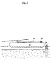
- Fig. 1
- eine schematische Darstellung der Errichtung der ersten Offshore-Windenergieanlage, wobei der Turm liegend auf einem Schiff befindlich dargestellt ist,
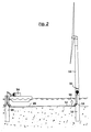
- Fig. 2
- eine schematische Darstellung des Ziehens des elektrischen Kabels von einer ersten Windenergieanlage, Gründungsbauteil einer zweiten Windenergieanlage, und
- Fig. 3
- eine schematische Darstellung des verlegten Kabels zwischen einer ersten und einer zweiten Windenergieanlage, wobei aus der zweiten Windenergieanlage erneut ein Kabel zu einer dritten Windenergieanlage verlegt wird.
- Fig. 1
- 1 shows a schematic representation of the construction of the first offshore wind energy installation, the tower being shown lying on a ship,
- Fig. 2
- a schematic representation of the pulling of the electrical cable from a first wind turbine, foundation component of a second wind turbine, and
- Fig. 3
- is a schematic representation of the laid cable between a first and a second wind turbine, wherein a cable is again laid to a third wind turbine from the second wind turbine.
Das in den Figuren beispielhaft dargestellte Verfahren
zum Verlegen elektrischer Kabel insbesondere innerhalb
eines Offshore-Windenergieparks zwischen einer Mehrzahl
von Windenergieanlagen schlägt vor, daß das zu verlegende
Kabel 14 bereits vor Errichtung des Turms einer ersten
Windenergienlage 10 in das Gründungsbauteil 16 oder in
den Turm der ersten Windenergieanlage 10 eingebracht
wird, wobei dies vorteilhafterweise bereits an Land geschehen
kann. Damit kann in einem Arbeitsgang sowohl der
Turm wie auch das Kabel 14 an den Ort der Errichtung gebracht
werden, und es erübrigt sich ein ansonsten nötiges
Manövrieren eines großen Kabelverlegeschiffes an zunächst
die erste errichtete Windkraftenergieanlage und dann an
die zweite Windkrafternergieanlage, wobei diese insbesondere
bei höheren Wellen durch das Schiff Beschädigungen
erleiden können.The method illustrated by way of example in the figures
for laying electrical cables, especially inside
an offshore wind farm between a plurality
of wind turbines suggests that the
Cable 14 before the first tower was erected
Weiter ist es, wie in der Fig. 2 erkennbar, ohne großen
Aufwand möglich, über eine Winde 24, die entweder auf dem
Gründungsbauteil 26 der zweiten Windkraftenergieanlage 20
vorgesehen werden kann oder auch auf einem kleinen Arbeitsboot,
eine zuvor ausgebrachte Schleppleine 22 aufzuwickeln,
um so das Kabel 14, das vorteilhafterweise mit
einem Schwimmer 28 an seinem Kabelende vom Meeresboden
ferngehalten wird, in die zweite Windkraftenergieanlage
20 oder dessen Gründungsbauteil 26 einzuziehen. Hierbei
kann der Turm der zweiten Windkraftenergieanlage 20 bereits
ausgebaut sein, oder, wie in der Fig. 2 dargestellt,
lediglich das Gründungsbauteil 26.Furthermore, as can be seen in FIG. 2, it is not large
Effort possible via a
Beim Errichten des Turmes der zweiten Windkraftenergieanlage
20 wird dann ein weiteres Kabel 14 für die Verbindung
zu einer dritten Windkraftenergieanlage mit aufgebaut.
Das eingezogene erste Kabel 14 muß dann nur noch
angeschlossen werden.When erecting the tower of the
Vorteilhaft ist ferner die Vorsehung von Umlenkrollen 18
in den Gründungsbauteilen 16, 26, wie in Fig. 3, wobei
diese vorteilhafterweise geringfügig über dem Meeresboden
angeordnet sind, um dem Kabel später eine optimale Lage
zu gewährleisten. In den Türmen oder den Gründungsbauteilen
gelagertes Kabel 14 kann dabei entweder meanderförmig
gelegt oder auf einer Trommel 30 aufgewickelt sein. Mit
Bezugszeichen 32 ist der Anschlußort für die elektrische
Verbindung der Kabel 14 in den Türmen der Windenergieanlagen
bezeichnet.The provision of
Claims (6)
- Method for laying electric cables from a first offshore wind power plant (10) to a second offshore wind power plant (20),
characterized byintroducing the cable (14) to be laid into the tower or foundation component (16) of the first offshore wind power plant (10) prior to the erection thereof,erecting at least the foundation component (16) of the first offshore wind power plant (10),bringing a tow line (22) from the first wind power plant (10, 20) to the second wind power plant (20, 10) andpulling the leading end of the cable (14) from the first wind power plant (10) to the second wind power plant (20), whilst allowing the cable (14) to pass out of the tower or foundation component (16) of the first wind power plant (10). - Method according to claim 1, characterized in that the electric cable (14) is laid in meandering manner in the tower or the foundation component (16) of the first wind power plant (10).
- Method according to claim 1, characterized in that the electric cable (14) is wound onto a drum (30) in the tower or the foundation component (16) of the first wind power plant (10).
- Method according to one of the preceding claims, characterized in that the electric cable (14) is guided by a guide pulley (18) fitted on the tower or foundation component (16) of the first wind power plant (10).
- Method according to claim 1, characterized in that a float (28) is fitted at least to the leading end of the electric cable (14).
- Method according to one of the preceding claims, characterized in that the electric cable (14) is drawn into the foundation component (16) or the tower of the second offshore wind power plant (20) by means of a winch (24) located in the vicinity of the second offshore wind power plant (20), prior the erection of the tower of the second wind power plant (20).
Applications Claiming Priority (3)
| Application Number | Priority Date | Filing Date | Title |
|---|---|---|---|
| DE19860211 | 1998-12-24 | ||
| DE19860211A DE19860211C1 (en) | 1998-12-24 | 1998-12-24 | Method for laying electrical cables from a first offshore wind turbine to a second offshore wind turbine |
| PCT/DE1999/003945 WO2000039903A1 (en) | 1998-12-24 | 1999-12-10 | Method for laying electrical cables from a first offshore wind power plant to a second offshore wind power plant |
Publications (2)
| Publication Number | Publication Date |
|---|---|
| EP1145397A1 EP1145397A1 (en) | 2001-10-17 |
| EP1145397B1 true EP1145397B1 (en) | 2002-08-21 |
Family
ID=7892762
Family Applications (1)
| Application Number | Title | Priority Date | Filing Date |
|---|---|---|---|
| EP99964414A Expired - Lifetime EP1145397B1 (en) | 1998-12-24 | 1999-12-10 | Method for laying electrical cables from a first offshore wind power plant to a second offshore wind power plant |
Country Status (10)
| Country | Link |
|---|---|
| US (1) | US6425708B1 (en) |
| EP (1) | EP1145397B1 (en) |
| JP (1) | JP4024000B2 (en) |
| CN (1) | CN1160844C (en) |
| AT (1) | ATE222670T1 (en) |
| AU (1) | AU3030800A (en) |
| DE (2) | DE19860211C1 (en) |
| DK (1) | DK1145397T3 (en) |
| ES (1) | ES2178498T3 (en) |
| WO (1) | WO2000039903A1 (en) |
Cited By (3)
| Publication number | Priority date | Publication date | Assignee | Title |
|---|---|---|---|---|
| DE102012013618B3 (en) * | 2012-07-10 | 2013-09-12 | Voith Patent Gmbh | Offshore power generation plant and assembly process |
| EP3225744A1 (en) * | 2016-03-29 | 2017-10-04 | AMBAU GmbH | Device for moving at least one flexible strand element, foundation structure with such a device, and method for moving at least one flexible strand element |
| EP3502353B1 (en) | 2017-12-22 | 2021-04-21 | Siemens Gamesa Renewable Energy A/S | Foundation building system for an offshore wind turbine and method for installation of an offshore wind turbine |
Families Citing this family (37)
| Publication number | Priority date | Publication date | Assignee | Title |
|---|---|---|---|---|
| DE19816483C2 (en) * | 1998-04-14 | 2003-12-11 | Aloys Wobben | Wind turbine |
| DE10145414B4 (en) | 2001-09-14 | 2013-09-12 | Aloys Wobben | Method for constructing a wind energy plant, wind energy plant |
| GB2394498B (en) | 2002-10-23 | 2006-08-09 | Engineering Business Ltd | Mounting of offshore structures |
| AU2004207180C1 (en) | 2003-02-01 | 2010-03-25 | Aloys Wobben | Method for the erection of a wind energy plant and wind energy plant |
| KR100702336B1 (en) * | 2003-02-12 | 2007-04-03 | 알로이즈 우벤 | Wind energy installation comprising premounted conductor rails in tower segments |
| US6860219B1 (en) * | 2003-03-17 | 2005-03-01 | Harry Edward Dempster | Technique and platform for fabricating a variable-buoyancy structure |
| GB0306547D0 (en) * | 2003-03-21 | 2003-04-23 | Engineering Business Ltd | Apparatus for creating a local reduction in wave height |
| DE602005011019D1 (en) * | 2004-08-03 | 2008-12-24 | Ihc Engineering Business Ltd | D DEVICE |
| GB0503083D0 (en) * | 2005-02-15 | 2005-03-23 | Engineering Business Ltd | Launch and recovery apparatus and method |
| GB2428656B (en) | 2005-08-01 | 2009-08-05 | Engineering Business Ltd | Gangway apparatus |
| GB2434823A (en) * | 2006-02-06 | 2007-08-08 | Engineering Business Ltd | Transport and installation of offshore structures |
| DK1985845T3 (en) * | 2007-04-26 | 2011-10-10 | Bard Holding Gmbh | Foundations for an offshore wind power plant with at least one submarine cable feed |
| ATE520181T1 (en) * | 2007-06-11 | 2011-08-15 | Vestas Wind Sys As | PIPE ARRANGEMENT FOR AN OFFSHORE PLANT |
| CN101903235A (en) * | 2007-12-21 | 2010-12-01 | 维斯塔斯风力系统集团公司 | Method for installing an offshore wind turbine and a barge system |
| DE102008018790A1 (en) | 2008-04-15 | 2009-10-22 | Wobben, Aloys | Wind energy plant with busbars |
| NL2005099C2 (en) * | 2010-07-16 | 2012-01-17 | Van Leeuwen Harmelen Bv Geb | Method and device for introducing an electrical cable at a depth in a seabed. |
| EP2606228B1 (en) * | 2010-08-20 | 2016-05-18 | Horton Wison Deepwater, Inc. | Offshore wind turbine and methods of installing same |
| GB201117069D0 (en) * | 2011-10-04 | 2011-11-16 | Tronic Ltd | .Installation method and system |
| US9249899B2 (en) * | 2011-10-07 | 2016-02-02 | Seaproof Solutions As | Cable pull-in with inflatable sealing section |
| EP2597738A1 (en) * | 2011-11-22 | 2013-05-29 | Seven Eighty X Limited | Method for mounting electrical cable and cable protection apparatus to support |
| CN104334874B (en) | 2012-06-08 | 2017-11-21 | 维斯塔斯风力系统集团公司 | Arrangement of the switching device in wind turbine tower |
| DE102012013615B3 (en) * | 2012-07-10 | 2013-09-12 | Voith Patent Gmbh | Offshore energy park and process for its creation |
| DE102012017379A1 (en) * | 2012-09-01 | 2014-03-06 | Strabag Offshore Wind Gmbh | A method for laying an offshore cable from a wind turbine to a destination and offshore wind turbine |
| NZ711017A (en) * | 2013-02-15 | 2017-02-24 | Prysmian Spa | Method for installing of a wet mateable connection assembly for electrical and/or optical cables |
| US20140342095A1 (en) * | 2013-05-16 | 2014-11-20 | Werner Krommer | Method for depositing an anticorrosive coating |
| JP6169006B2 (en) * | 2014-01-20 | 2017-07-26 | 古河電気工業株式会社 | Submarine cable, submarine cable laying structure, and submarine cable laying method |
| EP3323181B1 (en) * | 2015-07-15 | 2020-03-11 | Balmoral Comtec Limited | Variable length offshore cable and method of installation |
| CN105239572B (en) * | 2015-07-29 | 2017-06-06 | 龙源(北京)风电工程设计咨询有限公司 | A kind of large-diameter pile fan foundation structure offshore construction method |
| CN105610152B (en) * | 2016-01-13 | 2018-04-20 | 赵侠 | Ocean power Transmission equipment and its implementation |
| CN105490271B (en) * | 2016-01-13 | 2017-11-21 | 南京涵曦月自动化科技有限公司 | Maritime power conveyer and its implementation |
| CN105633953B (en) * | 2016-01-13 | 2017-11-28 | 赣州市金祥机械设备制造有限公司 | Offshore power grid system conveyer and its erection method |
| CN105633952B (en) * | 2016-01-13 | 2017-12-15 | 江西鑫固电气有限公司 | Power grid system transmission device and erection method thereof |
| CN105610114B (en) * | 2016-01-13 | 2017-11-03 | 江西鑫固电气有限公司 | Offshore power transmission device and implementation method thereof |
| ES2819423T3 (en) * | 2016-06-14 | 2021-04-16 | Fundacion Tecnalia Res & Innovation | Method of installing a submarine cable |
| EP3487018A1 (en) | 2017-11-15 | 2019-05-22 | Siemens Gamesa Renewable Energy A/S | Offshore structure and method for attaching a tube or cable to an appliance of an offshore structure |
| WO2019244249A1 (en) * | 2018-06-19 | 2019-12-26 | 日揮グローバル株式会社 | Device connection method for plant |
| EP3709458A1 (en) * | 2019-03-14 | 2020-09-16 | Siemens Gamesa Renewable Energy A/S | Method for offshore installing of power cables or tubes for power cables for wind turbine installations and seabed vehicle |
Family Cites Families (16)
| Publication number | Priority date | Publication date | Assignee | Title |
|---|---|---|---|---|
| DE1210275B (en) * | 1964-11-16 | 1966-02-03 | Hellmut Wulf Fa | Method for laying cables and flexible pipes under water using a cable plow |
| US3512367A (en) * | 1968-05-16 | 1970-05-19 | Exxon Production Research Co | Method and apparatus for laying pipe in deep water |
| US4228399A (en) * | 1978-02-27 | 1980-10-14 | Harco Corporation | Offshore pipeline electrical survey method and apparatus |
| US4309006A (en) * | 1979-06-04 | 1982-01-05 | Biscomb Lloyd I | Tethered airfoil wind energy conversion system |
| DE2922715A1 (en) * | 1979-06-05 | 1981-04-02 | Franz 2121 Deutsch Evern Anker | Combined wind and steam operated power station - formed on six-sided artificial island on sand-bank in open sea |
| AU5333079A (en) * | 1979-11-30 | 1981-06-04 | Barney Girden | Thermal sea power |
| US4423333A (en) * | 1982-02-02 | 1983-12-27 | Rossman Wendell E | Horizontal axis wind energy conversion system with aerodynamic blade pitch control |
| DE3224976A1 (en) * | 1982-07-03 | 1984-01-05 | Erno Raumfahrttechnik Gmbh, 2800 Bremen | Wind-energy converter in the offshore sector |
| US4492875A (en) * | 1982-12-02 | 1985-01-08 | The United States Of America As Represented By The Secretary Of The Navy | Wave powered buoy generator |
| US4565929A (en) * | 1983-09-29 | 1986-01-21 | The Boeing Company | Wind powered system for generating electricity |
| US4707041A (en) * | 1986-12-15 | 1987-11-17 | Hughes Tool Company | Subsea well electrical coupling system |
| DE3939862C2 (en) * | 1989-12-01 | 1996-07-11 | Heidelberg Goetz | Wind turbine |
| KR19980026177A (en) * | 1996-10-08 | 1998-07-15 | 오상수 | Car generator |
| KR100269764B1 (en) * | 1996-11-30 | 2000-10-16 | 심현진 | Generating device of electronic power using wind force |
| GB9708633D0 (en) * | 1997-04-29 | 1997-06-18 | Kvaerner Oil & Gas Ltd | Method of installing a tower |
| US5971665A (en) * | 1998-10-05 | 1999-10-26 | Oceaneering International Inc. | Cable-laying apparatus and method |
-
1998
- 1998-12-24 DE DE19860211A patent/DE19860211C1/en not_active Expired - Fee Related
-
1999
- 1999-12-10 WO PCT/DE1999/003945 patent/WO2000039903A1/en active IP Right Grant
- 1999-12-10 AT AT99964414T patent/ATE222670T1/en not_active IP Right Cessation
- 1999-12-10 DE DE59902424T patent/DE59902424D1/en not_active Expired - Lifetime
- 1999-12-10 AU AU30308/00A patent/AU3030800A/en not_active Abandoned
- 1999-12-10 DK DK99964414T patent/DK1145397T3/en active
- 1999-12-10 JP JP2000591704A patent/JP4024000B2/en not_active Expired - Fee Related
- 1999-12-10 ES ES99964414T patent/ES2178498T3/en not_active Expired - Lifetime
- 1999-12-10 CN CNB998135372A patent/CN1160844C/en not_active Expired - Fee Related
- 1999-12-10 EP EP99964414A patent/EP1145397B1/en not_active Expired - Lifetime
- 1999-12-10 US US09/868,970 patent/US6425708B1/en not_active Expired - Fee Related
Cited By (4)
| Publication number | Priority date | Publication date | Assignee | Title |
|---|---|---|---|---|
| DE102012013618B3 (en) * | 2012-07-10 | 2013-09-12 | Voith Patent Gmbh | Offshore power generation plant and assembly process |
| EP2700751A2 (en) | 2012-07-10 | 2014-02-26 | Voith Patent GmbH | Offshore energy generating installation and method of assembly |
| EP3225744A1 (en) * | 2016-03-29 | 2017-10-04 | AMBAU GmbH | Device for moving at least one flexible strand element, foundation structure with such a device, and method for moving at least one flexible strand element |
| EP3502353B1 (en) | 2017-12-22 | 2021-04-21 | Siemens Gamesa Renewable Energy A/S | Foundation building system for an offshore wind turbine and method for installation of an offshore wind turbine |
Also Published As
| Publication number | Publication date |
|---|---|
| DE19860211C1 (en) | 2000-11-23 |
| ES2178498T3 (en) | 2002-12-16 |
| WO2000039903A1 (en) | 2000-07-06 |
| AU3030800A (en) | 2000-07-31 |
| DK1145397T3 (en) | 2002-12-09 |
| EP1145397A1 (en) | 2001-10-17 |
| DE59902424D1 (en) | 2002-09-26 |
| ATE222670T1 (en) | 2002-09-15 |
| CN1326603A (en) | 2001-12-12 |
| JP2002534942A (en) | 2002-10-15 |
| JP4024000B2 (en) | 2007-12-19 |
| US6425708B1 (en) | 2002-07-30 |
| CN1160844C (en) | 2004-08-04 |
Similar Documents
| Publication | Publication Date | Title |
|---|---|---|
| EP1145397B1 (en) | Method for laying electrical cables from a first offshore wind power plant to a second offshore wind power plant | |
| EP2631368B1 (en) | Method and device for acoustic insulation | |
| DE102016118079B3 (en) | Mooring buoy for a floating wind turbine | |
| DE60123465T2 (en) | ENERGY GENERATION SYSTEM FOR USING MARINE WAVES ENERGY | |
| DE102008028476A1 (en) | Offshore-transformer station, has closed area comprising high voltage devices e.g. transformer, and connected with substructure, and cables drawn-into closed area after attaching high voltage devices to closed area | |
| EP4005046A1 (en) | Power cable assembly for offshore wind farms | |
| DE69812624T2 (en) | METHOD FOR RAISING A MAST AND DEVICE THEREFOR | |
| EP3341282A1 (en) | Drum for a towed-antenna winch for a towed antenna, towed antenna for towing in water, and ship for towing a towed antenna in water | |
| DE3013169A1 (en) | METHOD AND SYSTEM FOR COLLECTING A LENGTH OF A LONG-STRETCHED BODY, EXAMPLE OF A TUBE, AN ELECTRIC CABLE OR THE LIKE. | |
| EP3530809B1 (en) | Connecting structure for a marine installation | |
| DE4128513A1 (en) | METHOD AND DEVICE FOR FELTING OR RECHARGING THE SUPPLY CABLE OF AN UNDERWATER DEVICE | |
| DE102011117162A1 (en) | Offshore platform construction | |
| DE3112702A1 (en) | LIFTING DEVICE FOR AN OFFSHORE CONSTRUCTION | |
| DE102016109108A1 (en) | Drum for a towed antenna, winch, towing antenna and watercraft | |
| DD202325A5 (en) | DEVICE FOR GENERATING ELECTRICAL ENERGY BY USING AND CONTROLLING THE POTENTIAL ENERGY OF THE SEAWATER | |
| EP1389581A1 (en) | Method and apparatus for supply and maintenance of constructions at sea | |
| EP3495312A1 (en) | Lifting device and method for using the lifting device | |
| EP3081701B1 (en) | Method and device for acoustic insulation | |
| DE2535559A1 (en) | DEVICE FOR GUIDING A SHIP FOR LAYING LINES | |
| DE4423059A1 (en) | Installation of a stator in a housing | |
| DE102021105973A1 (en) | Covering a component opening of a component, in particular an offshore structure | |
| EP4344990A1 (en) | Solar floating device | |
| DE102014224466B3 (en) | Underwater current power plant | |
| DE102021118328A1 (en) | Offshore wind farm with a plurality of floating single-point mooring wind turbines | |
| DE202024102590U1 (en) | Platform system for a wind turbine |
Legal Events
| Date | Code | Title | Description |
|---|---|---|---|
| PUAI | Public reference made under article 153(3) epc to a published international application that has entered the european phase |
Free format text: ORIGINAL CODE: 0009012 |
|
| 17P | Request for examination filed |
Effective date: 20010421 |
|
| AK | Designated contracting states |
Kind code of ref document: A1 Designated state(s): AT BE CH CY DE DK ES FI FR GB GR IE IT LI LU MC NL PT SE |
|
| AX | Request for extension of the european patent |
Free format text: LT;LV PAYMENT 20010421 |
|
| GRAG | Despatch of communication of intention to grant |
Free format text: ORIGINAL CODE: EPIDOS AGRA |
|
| 17Q | First examination report despatched |
Effective date: 20020305 |
|
| GRAG | Despatch of communication of intention to grant |
Free format text: ORIGINAL CODE: EPIDOS AGRA |
|
| GRAH | Despatch of communication of intention to grant a patent |
Free format text: ORIGINAL CODE: EPIDOS IGRA |
|
| GRAH | Despatch of communication of intention to grant a patent |
Free format text: ORIGINAL CODE: EPIDOS IGRA |
|
| GRAA | (expected) grant |
Free format text: ORIGINAL CODE: 0009210 |
|
| AK | Designated contracting states |
Kind code of ref document: B1 Designated state(s): AT BE CH CY DE DK ES FI FR GB GR IE IT LI LU MC NL PT SE |
|
| AX | Request for extension of the european patent |
Free format text: LT PAYMENT 20010421;LV PAYMENT 20010421 |
|
| PG25 | Lapsed in a contracting state [announced via postgrant information from national office to epo] |
Ref country code: IT Free format text: LAPSE BECAUSE OF FAILURE TO SUBMIT A TRANSLATION OF THE DESCRIPTION OR TO PAY THE FEE WITHIN THE PRE;WARNING: LAPSES OF ITALIAN PATENTS WITH EFFECTIVE DATE BEFORE 2007 MAY HAVE OCCURRED AT ANY TIME BEFORE 2007. THE CORRECT EFFECTIVE DATE MAY BE DIFFERENT FROM THE ONE RECORDED.SCRIBED TIME-LIMIT Effective date: 20020821 |
|
| REF | Corresponds to: |
Ref document number: 222670 Country of ref document: AT Date of ref document: 20020915 Kind code of ref document: T |
|
| REG | Reference to a national code |
Ref country code: GB Ref legal event code: FG4D Free format text: NOT ENGLISH |
|
| REG | Reference to a national code |
Ref country code: CH Ref legal event code: EP |
|
| GBT | Gb: translation of ep patent filed (gb section 77(6)(a)/1977) |
Effective date: 20020821 |
|
| REF | Corresponds to: |
Ref document number: 59902424 Country of ref document: DE Date of ref document: 20020926 |
|
| REG | Reference to a national code |
Ref country code: IE Ref legal event code: FG4D Free format text: GERMAN |
|
| ET | Fr: translation filed | ||
| REG | Reference to a national code |
Ref country code: DK Ref legal event code: T3 |
|
| PG25 | Lapsed in a contracting state [announced via postgrant information from national office to epo] |
Ref country code: LU Free format text: LAPSE BECAUSE OF NON-PAYMENT OF DUE FEES Effective date: 20021210 Ref country code: AT Free format text: LAPSE BECAUSE OF NON-PAYMENT OF DUE FEES Effective date: 20021210 |
|
| REG | Reference to a national code |
Ref country code: ES Ref legal event code: FG2A Ref document number: 2178498 Country of ref document: ES Kind code of ref document: T3 |
|
| REG | Reference to a national code |
Ref country code: GR Ref legal event code: EP Ref document number: 20020403925 Country of ref document: GR |
|
| PG25 | Lapsed in a contracting state [announced via postgrant information from national office to epo] |
Ref country code: CY Free format text: LAPSE BECAUSE OF FAILURE TO SUBMIT A TRANSLATION OF THE DESCRIPTION OR TO PAY THE FEE WITHIN THE PRESCRIBED TIME-LIMIT Effective date: 20021231 |
|
| PG25 | Lapsed in a contracting state [announced via postgrant information from national office to epo] |
Ref country code: PT Free format text: LAPSE BECAUSE OF FAILURE TO SUBMIT A TRANSLATION OF THE DESCRIPTION OR TO PAY THE FEE WITHIN THE PRESCRIBED TIME-LIMIT Effective date: 20030122 |
|
| LTIE | Lt: invalidation of european patent or patent extension |
Effective date: 20020821 |
|
| PLBE | No opposition filed within time limit |
Free format text: ORIGINAL CODE: 0009261 |
|
| STAA | Information on the status of an ep patent application or granted ep patent |
Free format text: STATUS: NO OPPOSITION FILED WITHIN TIME LIMIT |
|
| PG25 | Lapsed in a contracting state [announced via postgrant information from national office to epo] |
Ref country code: MC Free format text: LAPSE BECAUSE OF NON-PAYMENT OF DUE FEES Effective date: 20030701 |
|
| 26N | No opposition filed |
Effective date: 20030522 |
|
| PG25 | Lapsed in a contracting state [announced via postgrant information from national office to epo] |
Ref country code: LI Free format text: LAPSE BECAUSE OF NON-PAYMENT OF DUE FEES Effective date: 20031231 Ref country code: CH Free format text: LAPSE BECAUSE OF NON-PAYMENT OF DUE FEES Effective date: 20031231 |
|
| REG | Reference to a national code |
Ref country code: CH Ref legal event code: PL |
|
| PGFP | Annual fee paid to national office [announced via postgrant information from national office to epo] |
Ref country code: NL Payment date: 20081216 Year of fee payment: 10 Ref country code: IE Payment date: 20081229 Year of fee payment: 10 |
|
| PGFP | Annual fee paid to national office [announced via postgrant information from national office to epo] |
Ref country code: FI Payment date: 20081215 Year of fee payment: 10 Ref country code: ES Payment date: 20081217 Year of fee payment: 10 |
|
| PGFP | Annual fee paid to national office [announced via postgrant information from national office to epo] |
Ref country code: FR Payment date: 20081212 Year of fee payment: 10 |
|
| PGFP | Annual fee paid to national office [announced via postgrant information from national office to epo] |
Ref country code: GR Payment date: 20081218 Year of fee payment: 10 |
|
| PGFP | Annual fee paid to national office [announced via postgrant information from national office to epo] |
Ref country code: BE Payment date: 20090130 Year of fee payment: 10 |
|
| BERE | Be: lapsed |
Owner name: *AERODYN ENGINEERING G.M.B.H. Effective date: 20091231 |
|
| REG | Reference to a national code |
Ref country code: NL Ref legal event code: V1 Effective date: 20100701 |
|
| PG25 | Lapsed in a contracting state [announced via postgrant information from national office to epo] |
Ref country code: FI Free format text: LAPSE BECAUSE OF NON-PAYMENT OF DUE FEES Effective date: 20091210 |
|
| REG | Reference to a national code |
Ref country code: FR Ref legal event code: ST Effective date: 20100831 |
|
| REG | Reference to a national code |
Ref country code: IE Ref legal event code: MM4A |
|
| PG25 | Lapsed in a contracting state [announced via postgrant information from national office to epo] |
Ref country code: NL Free format text: LAPSE BECAUSE OF NON-PAYMENT OF DUE FEES Effective date: 20100701 Ref country code: IE Free format text: LAPSE BECAUSE OF NON-PAYMENT OF DUE FEES Effective date: 20091210 Ref country code: FR Free format text: LAPSE BECAUSE OF NON-PAYMENT OF DUE FEES Effective date: 20091231 Ref country code: BE Free format text: LAPSE BECAUSE OF NON-PAYMENT OF DUE FEES Effective date: 20091231 |
|
| PGFP | Annual fee paid to national office [announced via postgrant information from national office to epo] |
Ref country code: DK Payment date: 20101210 Year of fee payment: 12 |
|
| REG | Reference to a national code |
Ref country code: ES Ref legal event code: FD2A Effective date: 20110329 |
|
| PGFP | Annual fee paid to national office [announced via postgrant information from national office to epo] |
Ref country code: GB Payment date: 20101221 Year of fee payment: 12 |
|
| PGFP | Annual fee paid to national office [announced via postgrant information from national office to epo] |
Ref country code: DE Payment date: 20101222 Year of fee payment: 12 |
|
| PG25 | Lapsed in a contracting state [announced via postgrant information from national office to epo] |
Ref country code: ES Free format text: LAPSE BECAUSE OF NON-PAYMENT OF DUE FEES Effective date: 20110316 |
|
| PG25 | Lapsed in a contracting state [announced via postgrant information from national office to epo] |
Ref country code: ES Free format text: LAPSE BECAUSE OF NON-PAYMENT OF DUE FEES Effective date: 20091211 |
|
| PGFP | Annual fee paid to national office [announced via postgrant information from national office to epo] |
Ref country code: SE Payment date: 20111223 Year of fee payment: 13 |
|
| PG25 | Lapsed in a contracting state [announced via postgrant information from national office to epo] |
Ref country code: SE Free format text: LAPSE BECAUSE OF NON-PAYMENT OF DUE FEES Effective date: 20121211 |
|
| REG | Reference to a national code |
Ref country code: DK Ref legal event code: EBP |
|
| GBPC | Gb: european patent ceased through non-payment of renewal fee |
Effective date: 20121210 |
|
| REG | Reference to a national code |
Ref country code: DE Ref legal event code: R119 Ref document number: 59902424 Country of ref document: DE Effective date: 20130702 |
|
| PG25 | Lapsed in a contracting state [announced via postgrant information from national office to epo] |
Ref country code: DE Free format text: LAPSE BECAUSE OF NON-PAYMENT OF DUE FEES Effective date: 20130702 |
|
| PG25 | Lapsed in a contracting state [announced via postgrant information from national office to epo] |
Ref country code: GB Free format text: LAPSE BECAUSE OF NON-PAYMENT OF DUE FEES Effective date: 20121210 |
|
| PG25 | Lapsed in a contracting state [announced via postgrant information from national office to epo] |
Ref country code: DK Free format text: LAPSE BECAUSE OF NON-PAYMENT OF DUE FEES Effective date: 20130102 |