EP1145067B1 - Confocal microscopy apparatus and method - Google Patents
Confocal microscopy apparatus and method Download PDFInfo
- Publication number
- EP1145067B1 EP1145067B1 EP00900715A EP00900715A EP1145067B1 EP 1145067 B1 EP1145067 B1 EP 1145067B1 EP 00900715 A EP00900715 A EP 00900715A EP 00900715 A EP00900715 A EP 00900715A EP 1145067 B1 EP1145067 B1 EP 1145067B1
- Authority
- EP
- European Patent Office
- Prior art keywords
- image
- mask
- confocal
- light
- specimen
- Prior art date
- Legal status (The legal status is an assumption and is not a legal conclusion. Google has not performed a legal analysis and makes no representation as to the accuracy of the status listed.)
- Expired - Lifetime
Links
- 238000004624 confocal microscopy Methods 0.000 title claims description 26
- 238000000034 method Methods 0.000 title claims description 15
- 238000000059 patterning Methods 0.000 claims description 42
- 230000003287 optical effect Effects 0.000 claims description 10
- 238000005286 illumination Methods 0.000 claims description 7
- 238000000386 microscopy Methods 0.000 description 14
- 238000003384 imaging method Methods 0.000 description 9
- 238000001514 detection method Methods 0.000 description 5
- 238000010586 diagram Methods 0.000 description 4
- 239000012620 biological material Substances 0.000 description 2
- 230000031018 biological processes and functions Effects 0.000 description 2
- 230000000694 effects Effects 0.000 description 2
- 238000000605 extraction Methods 0.000 description 2
- 230000001788 irregular Effects 0.000 description 2
- 238000010606 normalization Methods 0.000 description 2
- 239000004065 semiconductor Substances 0.000 description 2
- 238000004611 spectroscopical analysis Methods 0.000 description 2
- 239000012472 biological sample Substances 0.000 description 1
- 230000005540 biological transmission Effects 0.000 description 1
- 230000000295 complement effect Effects 0.000 description 1
- 238000010226 confocal imaging Methods 0.000 description 1
- 238000001218 confocal laser scanning microscopy Methods 0.000 description 1
- 238000011161 development Methods 0.000 description 1
- 230000018109 developmental process Effects 0.000 description 1
- 239000000284 extract Substances 0.000 description 1
- 238000000799 fluorescence microscopy Methods 0.000 description 1
- 238000001506 fluorescence spectroscopy Methods 0.000 description 1
- 238000012632 fluorescent imaging Methods 0.000 description 1
- 238000007689 inspection Methods 0.000 description 1
- 239000000463 material Substances 0.000 description 1
- 239000012780 transparent material Substances 0.000 description 1
Images



Classifications
-
- G—PHYSICS
- G02—OPTICS
- G02B—OPTICAL ELEMENTS, SYSTEMS OR APPARATUS
- G02B21/00—Microscopes
- G02B21/0004—Microscopes specially adapted for specific applications
- G02B21/002—Scanning microscopes
- G02B21/0024—Confocal scanning microscopes (CSOMs) or confocal "macroscopes"; Accessories which are not restricted to use with CSOMs, e.g. sample holders
- G02B21/0052—Optical details of the image generation
- G02B21/0076—Optical details of the image generation arrangements using fluorescence or luminescence
-
- G—PHYSICS
- G02—OPTICS
- G02B—OPTICAL ELEMENTS, SYSTEMS OR APPARATUS
- G02B21/00—Microscopes
- G02B21/0004—Microscopes specially adapted for specific applications
- G02B21/002—Scanning microscopes
- G02B21/0024—Confocal scanning microscopes (CSOMs) or confocal "macroscopes"; Accessories which are not restricted to use with CSOMs, e.g. sample holders
-
- G—PHYSICS
- G02—OPTICS
- G02B—OPTICAL ELEMENTS, SYSTEMS OR APPARATUS
- G02B21/00—Microscopes
- G02B21/0004—Microscopes specially adapted for specific applications
- G02B21/002—Scanning microscopes
- G02B21/0024—Confocal scanning microscopes (CSOMs) or confocal "macroscopes"; Accessories which are not restricted to use with CSOMs, e.g. sample holders
- G02B21/0052—Optical details of the image generation
-
- G—PHYSICS
- G02—OPTICS
- G02B—OPTICAL ELEMENTS, SYSTEMS OR APPARATUS
- G02B21/00—Microscopes
- G02B21/0004—Microscopes specially adapted for specific applications
- G02B21/002—Scanning microscopes
- G02B21/0024—Confocal scanning microscopes (CSOMs) or confocal "macroscopes"; Accessories which are not restricted to use with CSOMs, e.g. sample holders
- G02B21/0052—Optical details of the image generation
- G02B21/0056—Optical details of the image generation based on optical coherence, e.g. phase-contrast arrangements, interference arrangements
-
- G—PHYSICS
- G02—OPTICS
- G02B—OPTICAL ELEMENTS, SYSTEMS OR APPARATUS
- G02B21/00—Microscopes
- G02B21/0004—Microscopes specially adapted for specific applications
- G02B21/002—Scanning microscopes
- G02B21/0024—Confocal scanning microscopes (CSOMs) or confocal "macroscopes"; Accessories which are not restricted to use with CSOMs, e.g. sample holders
- G02B21/0052—Optical details of the image generation
- G02B21/0068—Optical details of the image generation arrangements using polarisation
-
- G—PHYSICS
- G02—OPTICS
- G02B—OPTICAL ELEMENTS, SYSTEMS OR APPARATUS
- G02B21/00—Microscopes
- G02B21/0004—Microscopes specially adapted for specific applications
- G02B21/002—Scanning microscopes
- G02B21/0024—Confocal scanning microscopes (CSOMs) or confocal "macroscopes"; Accessories which are not restricted to use with CSOMs, e.g. sample holders
- G02B21/008—Details of detection or image processing, including general computer control
- G02B21/0084—Details of detection or image processing, including general computer control time-scale detection, e.g. strobed, ultra-fast, heterodyne detection
Definitions
- the present invention relates to a confocal microscopy apparatus and method and in particular to confocal microscopy apparatus that enables real-time imaging to be performed.
- Confocal microscope systems were originally designed to generate a substantially pure confocal image by scanning a diffraction limited spot of light across the object being imaged. Light reflected from separate scanned points of the object was sequentially received by a series of photodetectors to gradually build up a 2-D confocal image of the object.
- Such confocal systems have the disadvantage that a very bright light source such as a laser is necessary and real-time imaging could not easily be performed because of the time required to scan over the surface of the object.
- WO97131282 a confocal microscope is described in which a mask is used to generate a combined confocal and non-confocal image. The non-confocal image is subsequently subtracted from the combined image to provide a substantially pure confocal image.
- the mask in WO97/31282 consists of different, separated regions with a first region being substantially transparent to incident light and unpatterned and a second region being patterned, for example with an irregular array of spots that are opaque to incident light. Light that passes through the first region illuminates the object to generate a conventional image of the object.
- light that passes through the second region produces a pattern of the mask on the surface of the object that in turn generates a combined confocal and conventional image of the object.
- the mask is spun so that the first and second regions of the mask alternately transmit the illumination to the object and so generate alternate images of the object.
- the alternate images are then subtracted from one another so that the conventional image is removed from the combined image to leave only the confocal image.
- a confocal microscope An alternative theoretical design of a confocal microscope is described in a paper that appeared in the Journal of Microscopy, Vol. 189, Pt 3, March 1998 entitled “Theory of confocal fluorescence imaging in the programmable array microscope (PAM)", Verveer et al.
- the programmable array microscope described in this paper consists of a spatial light modulator (SLM) in the form of a digital micromirror device (DMD).
- SLM spatial light modulator
- DMD digital micromirror device
- the individual pixels of the SLM are programmed to generate an arbitrary pattern of conjugate illumination and detection apertures and two separate cameras are used, one positioned to view active ('on') micromirrors of the SLM and to receive the confocal reflected light from the object and one to view inactive ('off) micromirrors and to receive a nonconjugate image of the object.
- two separate cameras are used, one positioned to view active ('on') micromirrors of the SLM and to receive the confocal reflected light from the object and one to view inactive ('off) micromirrors and to receive a nonconjugate image of the object.
- the present invention seeks to provide improved confocal microscopy apparatus that enables real-time imaging of an object and generates images containing less noise than is generally possible with current systems.
- the present invention provides Confocal microscopy apparatus comprising means for directing light to a specimen; a mask for encoding light incident on the specimen and for decoding light from the specimen; and one or more image detectors for detecting first and second images of the specimen, the first image consisting of a confocal image superimposed on a non-confocal image and the second image consisting of a non-confocal image from which a confocal image has been removed characterised in that the mask, having opposing first and second surfaces, has transparent / opaque patterning on its first surface so as to encode, by spatial modulation of its intensity, light incident on this surface and transmitted through the mask and reflective patterning on the second surface that is substantially identical to the opaque patterning on the first surface so as to encode light incident on and reflected from the second surface in reverse to the encoding provided by the transparent / opaque patterning; whereby one of the first and second surfaces of the mask generates the first image of the specimen and the other of the first and second surfaces of the mask generates the second image of the specimen
- analysing means are provided for generating a confocal image of the specimen using the first and second images.
- the microscopy apparatus may include one or more light sources.
- two light sources may be provided to illuminate each side of the mask respectively.
- the detection means may detect both the first and second images.
- a second detection means may be provided for detecting the second image, the first and second detection means being located on opposite sides of the mask.
- the second detection means may be located to receive light reflected from said reflective patterning.
- the mask may be patterned with equidistant light transmissive stripes and light barring stripes or with a random patterning. Also, the mask may be mounted for rotation about the optical axis of the apparatus.
- the present invention provides a confocal microscopy method comprising providing illumination from a first light source; encoding light incident on a specimen and decoding light from the specimen by means of a mask; and detecting first and second images of the specimen, the first image consisting of a confocal image superimposed on a non-confocal image and the second image consisting of a non-confocal image from which a confocal image has been removed characterised in that the mask, having opposing first and second surfaces, has transparent / opaque patterning on its first surface thereby encoding, by spatial modulation of its intensity, light incident on this surface and transmitted through the mask and reflective patterning on the second surface that is substantially identical to the opaque patterning on the first surface thereby encoding light incident on and reflected from the second surface in reverse to the encoding provided by the transparent / opaque patterning, the method thereby including generating the first image of the specimen by means of one of the first or second surfaces of the mask and generating the second image of the specimen by means of
- the method further comprises generating a confocal image from said first and second images.
- the second image is subtracted from the first image to extract the confocal image.
- the mask is rotatable.
- the microscopy apparatus includes a first light source 1 with an associated collimating lens 2 and a beam splitter 3 for directing light from the first light source 1 through an objective lens 4 to an object O or specimen supported on a mount 5.
- the beam splitter 3 may be a semi-silvered mirror, as shown in Figure 1.
- a polarising beam splitter may be used in combination with a quarter waveplate located between the mask 6 and the object O so as to minimise the effect of spurious reflections.
- a dichroic beam splitter may conveniently be used.
- a mask 6 is provided across the main optical axis X of the microscopy apparatus such that a first surface of the mask 6a is illuminated by the first light source 1.
- the mask 6 is encoded with a predetermined pattern that modulates spatially in the plane of the mask the light from the first light source 1.
- the mask 6 has transparent and opaque patterning that extends through the mask from its first surface 6a to its opposing second surface 6b.
- the patterning covers substantially all of the first and second surfaces of the mask.
- the patterning may be in the form of regular stripes of substantially opaque material separated by stripes of substantially transparent material.
- the patterning may be formed by an array of small spots or a wholly irregular pattern.
- the patterning may be determined using finite length binary time sequences such as time-shifted complementary Golay sequences with the number of sequences in the set limited to the sequence length.
- the ratio of the transparent and opaque patterning is preferably 1:1 so as to maximise the light budget of the microscopy apparatus. Where the ratio is other than 1:1, the difference in the light transmitted/blocked by the patterning should be accommodated by normalisation factors employed in the extraction of the confocal image.
- the size of the patteming of the mask 6 is determined by the optical arrangement of the microscopy apparatus to the extent that the patterning must be resolvable on the object O.
- the mask 6 is mounted with its normal at a small angle, for example a few degrees, to the main optical axis X of the apparatus.
- the angle is sufficiently small that it has only a nominal effect to the final imaging of the mask pattern on the object.
- the mask is mounted on an axle (not shown) for rotation about its normal.
- the mask 6 may be fixed so that no rotation is permitted depending upon the type of patterning employed for the mask 6.
- the beam splitter 3 is positioned to reflect light from the light source 1 towards the mask 6 and to allow light from the mask 6 to pass through to a camera 7.
- the camera 7 is preferably a CCD camera, however, alternative two dimensional image detectors may be employed such as a simple array of photodetectors.
- a second light source 8 and an associated collimating lens 9 are also provided off the main optical axis of the apparatus so as to illuminate the second surface 6b of the mask that faces towards the object O.
- the second surface 6b of the mask bears reflective patterning that is substantially identical to the opaque patterning of the first surface of the mask.
- the opaque patterning is made reflective at least on the second surface 6b of the mask. In this way it is ensured that the reflective patterning is identical to the opaque patterning which encodes light from the first light source 1.
- the second surface 6b of the mask 6 presents a reflective patterning to light from the second light source 8.
- the first and second light sources 1, 8 illuminate the mask 6 with substantially identical intensity.
- predetermined normalisation factors can be employed during extraction of the confocal image to accommodate any differences between the intensities of the two light sources.
- Figure 1 shows two separate light sources alternatively, a single light source may be used that can be re-directed to illuminate either the first or second faces of the mask 6. This has the advantage of ensuring matched illumination of the mask.
- the light sources are preferably in the form of light emitting diodes (LEDs). However, alternative light sources such as incandescent lamps, arc lamps or lasers may be employed. Arc lamps are particularly desirable where fluorescent imaging of biological samples is to be performed.
- the object O is alternately illuminated by the first and second light sources 1 and 8.
- the light is reflected by the beam splitter 3 and is encoded by the mask 6 as it passes through the mask.
- the light thus forms an image of the opaque patterning of the mask on the object O at a predetermined plane.
- the encoded light is then reflected by the object O back through the mask 6 to the beam splitter 3.
- the reflected light returns through the mask 6, the light is decoded by the patterning of the mask.
- the decoded light then passes through the beam splitter 3 to the camera 7.
- the image, referred to as the first or positive image, received by the camera 7 is thus a combination of a conventional image I conv superimposed with a confocal image I conf with the confocal image being produced from the encoded light that is focused on the object at the focal plane and is accurately decoded by the mask 6.
- light from the second light source 8 is reflected by the reflective patterning of the mask 6 at the second surface 6b to the object O to produce a reverse image of the opaque patterning on the object O at the focal plane.
- the encoding of the light from the second light source 8 is the reverse of the encoding of the light from the first light source 1.
- the light encoded by the reflective patterning is reflected by the object O back to the second surface 6b of the mask 6 and thence to the camera 7.
- the image, referred to as the second or negative image, received by the camera 7 is thus a conventional image I conv minus the confocal image I conf as the confocal image has not been transmitted by the mask to the camera7.
- the positive and negative images produced using the first and second light sources are then transferred to an analyser 10 which subtracts the negative image from the positive image, i.e. (I conv +I conf )-(I conv -I conf ).
- the resultant image 2 I conf is a confocal image having twice the intensity of confocal images produced using previous confocal microscopy systems. This in turn significantly increases the signal to noise ratio in the confocal images produced using the microscopy apparatus and method described above.
- the conventional image I conv may also be extracted by the analyser 10 by the addition of the positive and negative images. The conventional image is particularly useful in navigating around the object being imaged. As mentioned above, the positive and negative images may be normalised where necessary to accommodate differences in the intensity of the illuminating beams.
- each positive image and each negative image can be used twice with its corresponding neighbours in time.
- the microscopy apparatus is particularly suited to the confocal imaging of dynamic systems.
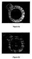
- Figure 5a is a positive image, (I conv +I conf ), of a semiconductor transistor using the microscopy apparatus and method shown in Figure 1 using a polarising beam splitter and LEDs as light sources.
- Figure 5b is the negative image, (I conv -I conf ), of the same transistor at the same focal plane.
- Figure 5c the confocal image extracted from the positive and negative images of Figures 5a and 5b is shown and Figure 5d shows the extracted conventional image. It will be immediately apparent from Figure 5c that the microscopy apparatus describe above is able to produce a particularly clear and strong confocal image.
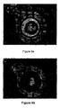
- Figures 6a to 6d are further positive, negative, confocal and conventional images respectively of the same transistor at a second focal plane.
- each light source was operated at a frequency of 25/2 Hz.
- the object could be illuminated at faster speeds, if necessary or at much slower speeds where real-time imaging is not required.
- the light source itself may be turned on and off at the desired speed or alternatively, the output of the light source may be shuttered to control the illumination of the object. Rotation of the disc at high speed enables the pattern of stripes on the disc to be removed from the final positive and negative images as the images can be integrated to average out the pattern of stripes.
- a single light source 1 is used instead of two light sources.
- the second surface 6b of the mask is reflective and the normal of the mask is set at a small angle, for example between 2° and 15°, to the main optical axis X of the apparatus.
- the second light source is replaced by a second camera 11.
- a positive image is recorded by the first camera 7
- the negative image is simultaneously recorded by the second camera 11 from light reflected from the second surface of the mask 6.
- Both images are transmitted to the analyser 10 which then extracts the confocal image from the positive and negative images.
- This arrangement has the advantage that both images are produced simultaneously and so the confocal images can be produced approximately twice as fast.
- the light budget is maximised as all available light is recorded either by the first or second cameras.
- this arrangement introduces greater difficulties with alignment as compared with the two light source system.
- FIG 3 a further alternative embodiment is shown in which two light sources are used.
- This embodiment is similar to the first embodiment except that the camera 7 is moved so that it only receives images reflected from the second surface 6b of the mask.
- the first light source 1 generates the negative image and it is the second light source 8, on the same side of the mask as the camera 7, that generates the positive images.
- Figure 4 which is similar to Figure 2 in that the apparatus includes two cameras 7 and 11. With this alternative arrangement the first camera 7 receives the negative image and the second camera 11, on the same side of the mask 6 as the light source 8 receives the positive image.
- three-dimensional confocal images may be produced using the microscopy apparatus and method described above by creating a plurality of two-dimensional confocal images at different focal planes that are used to construct the three-dimensional image.
- the microscopy apparatus and method described above is suitable for most situations where confocal images are required.
- the apparatus and method is particularly suited for real-time imaging of biological processes and quality inspections for example of semiconductor chips.
- the object is not highly reflective in which case light scattered from the object is used to extract the confocal image.
- the incident light is not reflected by the object but rather is used to stimulate an equivalent pattern of fluorescence.
- the incident light is encoded in the manner described above and this pattern of light incident on the biological material stimulates fluorescence.
- the pattern of fluorescent light produced by the biological material is then decoded and positive and negative images are produced that can be subtracted to extract the confocal image in exactly the same way as described above.
- the confocal microscopy apparatus may be implemented in a conventional microscope through the addition of the encoded mask and either a second light source or a second camera.
Landscapes
- Physics & Mathematics (AREA)
- Chemical & Material Sciences (AREA)
- Analytical Chemistry (AREA)
- General Physics & Mathematics (AREA)
- Optics & Photonics (AREA)
- Engineering & Computer Science (AREA)
- Computer Vision & Pattern Recognition (AREA)
- General Engineering & Computer Science (AREA)
- Microscoopes, Condenser (AREA)
Description
Claims (14)
- Confocal microscopy apparatus comprising means (4) for directing light to a specimen (O); a mask (6) for encoding light incident on the specimen and for decoding light from the specimen; and one or more image detectors (7, 11) for detecting first and second images of the specimen, the first image consisting of a confocal image superimposed on a non-confocal image and the second image consisting of a non-confocal image from which a confocal image has been removed
characterised in that
the mask (6), having opposing first (6a) and second (6b) surfaces, has transparent / opaque patterning on its first surface (6a) so as to encode, by spatial modulation of its intensity, light incident on this surface and transmitted through the mask and reflective patterning on the second surface (6b) that is substantially identical to the opaque patterning on the first surface so as to encode light incident on and reflected from the second surface in reverse to the encoding provided by the transparent / opaque patterning
whereby one of the first (6a) and second (6b) surfaces of the mask generates the first image of the specimen and the other of the first (6a) and second (6b) surfaces of the mask generates the second image of the specimen. - Confocal microscopy apparatus as claimed in claim 1, wherein there is further provided analysing means (10) for generating a confocal image of the specimen using the first and second images.
- Confocal microscopy apparatus as claimed in either of claims 1 or 2, further including one or more light sources (1, 8).
- Confocal microscopy apparatus as claimed in claim 3, wherein two light sources (1, 8) are provided to illuminate each side (6a, 6b) of the mask respectively.
- Confocal microscopy apparatus as claimed in claim 4, wherein a single image detector (7) detects the first and second images.
- Confocal microscopy apparatus as claimed in claim 3, further including a second image detector (11) for detecting the second image, the first (7) and second (11) image detectors being located on opposite sides of the mask (6).
- Confocal microscopy apparatus as claimed in any one of the preceding claims, wherein the one or more image detectors (7, 11) are CCD cameras.
- Confocal microscopy apparatus as claimed in any one of the preceding claims, wherein the first surface (6a) of the mask is patterned with equidistant light transmissive stripes and light barring stripes.
- Confocal microscopy apparatus as claimed in any one of the preceding claims, wherein the first (6a) and second (6b) surfaces of the mask have a random patterning.
- Confocal microscopy apparatus as claimed in any one of the preceding claims, wherein the mask (6) is mounted for rotation about the optical axis of the apparatus.
- A confocal microscopy method comprising providing illumination from a first light source (1); encoding light incident on a specimen (O) and decoding light from the specimen by means of a mask (6); and detecting first and second images of the specimen, the first image consisting of a confocal image superimposed on a non-confocal image and the second image consisting of a non-confocal image from which a confocal image has been removed characterised in that the mask (6), having opposing first (6a) and second (6b) surfaces, has transparent / opaque patterning on its first surface (6a) thereby encoding, by spatial modulation of its intensity, light incident on this surface and transmitted through the mask and reflective patterning on the second surface (6b) that is substantially identical to the opaque patterning on the first surface thereby encoding light incident on and reflected from the second surface in reverse to the encoding provided by the transparent / opaque patterning, the method thereby including generating the first image of the specimen by means of one of the first (6a) or second (6b) surfaces of the mask and generating the second image of the specimen by means of the other of the first (6a) or second (6b) surfaces of the mask.
- A confocal microscopy method as claimed in claim 11, further comprising extracting a confocal image from said first and second images.
- A confocal microscopy method as claimed in claim 12, wherein the second image is subtracted from the first image to extract the confocal image.
- A confocal microscopy method as claimed in any one of claims 11 to 13, wherein the mask (6) is rotated.
Applications Claiming Priority (3)
| Application Number | Priority Date | Filing Date | Title |
|---|---|---|---|
| GBGB9901365.8A GB9901365D0 (en) | 1999-01-22 | 1999-01-22 | Confocal microscopy apparatus and method |
| GB9901365 | 1999-01-22 | ||
| PCT/GB2000/000142 WO2000043819A2 (en) | 1999-01-22 | 2000-01-17 | Confocal microscopy apparatus and method |
Publications (2)
| Publication Number | Publication Date |
|---|---|
| EP1145067A2 EP1145067A2 (en) | 2001-10-17 |
| EP1145067B1 true EP1145067B1 (en) | 2002-09-04 |
Family
ID=10846292
Family Applications (1)
| Application Number | Title | Priority Date | Filing Date |
|---|---|---|---|
| EP00900715A Expired - Lifetime EP1145067B1 (en) | 1999-01-22 | 2000-01-17 | Confocal microscopy apparatus and method |
Country Status (8)
| Country | Link |
|---|---|
| US (1) | US6687052B1 (en) |
| EP (1) | EP1145067B1 (en) |
| JP (1) | JP4558944B2 (en) |
| CA (1) | CA2360917C (en) |
| DE (1) | DE60000406T2 (en) |
| ES (1) | ES2179011T3 (en) |
| GB (1) | GB9901365D0 (en) |
| WO (1) | WO2000043819A2 (en) |
Cited By (1)
| Publication number | Priority date | Publication date | Assignee | Title |
|---|---|---|---|---|
| EP2930548A1 (en) | 2014-04-10 | 2015-10-14 | Carl Zeiss Microscopy GmbH | Device for microscopic applications |
Families Citing this family (38)
| Publication number | Priority date | Publication date | Assignee | Title |
|---|---|---|---|---|
| US7354389B2 (en) * | 2002-05-28 | 2008-04-08 | Autogenomics, Inc. | Microarray detector and methods |
| DE10245974A1 (en) * | 2002-10-02 | 2004-04-15 | Leica Mikroskopie Und Systeme Gmbh | Contrast modulation microscope has a modulator in each viewing path, with a layer changing with the phase/amplitude, for a continuous phase shift without numerous modulators |
| FR2848682B1 (en) * | 2002-12-13 | 2005-02-18 | Commissariat Energie Atomique | LIGHTING OPTICAL MICROSCOPE MODIFIABLE STRUCTURE |
| US7881502B2 (en) * | 2003-06-30 | 2011-02-01 | Weyerhaeuser Nr Company | Method and system for three-dimensionally imaging an apical dome of a plant embryo |
| EP1972983B1 (en) | 2003-07-04 | 2009-12-02 | Vincent Lauer | Scanning imaging device for confocal microscopy with image substraction |
| DE10339619A1 (en) * | 2003-08-28 | 2005-03-24 | Leica Microsystems (Schweiz) Ag | Stereomicroscope with integrated epi-illumination device |
| US7264794B2 (en) * | 2004-12-17 | 2007-09-04 | The General Hospital | Methods of in vivo cytometry |
| US7491502B2 (en) | 2004-12-17 | 2009-02-17 | The General Hospital Corporation | In vivo flow cytometry system and method |
| US7768638B2 (en) | 2005-03-18 | 2010-08-03 | Illumina, Inc. | Systems for and methods of facilitating focusing an optical scanner |
| US8523882B2 (en) | 2005-04-14 | 2013-09-03 | Ethicon Endo-Surgery, Inc. | Clip advancer mechanism with alignment features |
| US8038686B2 (en) * | 2005-04-14 | 2011-10-18 | Ethicon Endo-Surgery, Inc. | Clip applier configured to prevent clip fallout |
| US7297149B2 (en) * | 2005-04-14 | 2007-11-20 | Ethicon Endo-Surgery, Inc. | Surgical clip applier methods |
| US7261724B2 (en) * | 2005-04-14 | 2007-08-28 | Ethicon Endo-Surgery, Inc. | Surgical clip advancement mechanism |
| US7686820B2 (en) * | 2005-04-14 | 2010-03-30 | Ethicon Endo-Surgery, Inc. | Surgical clip applier ratchet mechanism |
| US7740641B2 (en) | 2005-04-14 | 2010-06-22 | Ethicon Endo-Surgery, Inc. | Clip applier with migrational resistance features |
| US7288098B2 (en) * | 2005-04-14 | 2007-10-30 | Ethicon Endo-Surgery, Inc. | Force limiting mechanism for medical instrument |
| DE102006027836B4 (en) * | 2006-06-16 | 2020-02-20 | Carl Zeiss Microscopy Gmbh | Microscope with auto focus device |
| EP2122409B1 (en) * | 2007-02-25 | 2016-12-07 | Humaneyes Technologies Ltd. | A method and a system for calibrating and/or visualizing a multi image display and for reducing ghosting artifacts |
| DE102007018048A1 (en) * | 2007-04-13 | 2008-10-16 | Michael Schwertner | Method and arrangement for optical imaging with depth discrimination |
| US20110060232A1 (en) * | 2007-05-04 | 2011-03-10 | The General Hospital Corporation | Retinal flow cytometry |
| WO2009013744A2 (en) * | 2007-07-23 | 2009-01-29 | Humaneyes Technologies Ltd. | Multi view displays and methods for producing the same |
| DE102007047468A1 (en) * | 2007-09-28 | 2009-04-02 | Carl Zeiss Microimaging Gmbh | Method and arrangement for optically detecting an illuminated sample |
| DE102007047460A1 (en) * | 2007-09-28 | 2009-04-09 | Carl Zeiss Meditec Ag | Apparatus and method for examining the ocular fundus, in particular the photoreceptors |
| US8574859B2 (en) * | 2008-03-27 | 2013-11-05 | The General Hospital Corporation | In vivo flow cytometry based on cellular autofluorescence |
| JP2010054981A (en) * | 2008-08-29 | 2010-03-11 | Hamamatsu Photonics Kk | Confocal microscope apparatus |
| US8262679B2 (en) * | 2009-10-09 | 2012-09-11 | Ethicon Endo-Surgery, Inc. | Clip advancer |
| US8267945B2 (en) * | 2009-10-09 | 2012-09-18 | Ethicon Endo-Surgery, Inc. | Clip advancer with lockout mechanism |
| JP5412394B2 (en) | 2010-09-30 | 2014-02-12 | オリンパス株式会社 | Sample observation equipment |
| US9370400B2 (en) | 2011-10-19 | 2016-06-21 | Ethicon Endo-Surgery, Inc. | Clip applier adapted for use with a surgical robot |
| DE102012208869A1 (en) * | 2012-05-25 | 2013-11-28 | Carl Zeiss Microscopy Gmbh | Scanning microscope and microscopy method |
| KR101181395B1 (en) | 2012-04-24 | 2012-09-19 | 나노스코프시스템즈 (주) | Multiple detection confocal microscope |
| JP6590513B2 (en) * | 2015-04-30 | 2019-10-16 | キヤノン株式会社 | Information processing apparatus, operating method thereof, and computer program |
| HU231246B1 (en) | 2015-08-31 | 2022-05-28 | 3Dhistech Kft | Confocal sample holder scanner |
| WO2017070146A1 (en) * | 2015-10-19 | 2017-04-27 | William Marsh Rice University | High resolution microendoscope employing differential structured illumination and method of using same |
| PT3411695T (en) | 2016-02-01 | 2022-03-03 | Kla Tencor Corp | Method and system for optical three-dimensional topography measurement |
| DE102018210606B4 (en) * | 2018-06-28 | 2025-10-02 | Carl Zeiss Microscopy Gmbh | Microscopic imaging method using a correction factor |
| US20230324665A1 (en) | 2020-08-25 | 2023-10-12 | Aurox Limited | Microscope |
| WO2024006242A1 (en) * | 2022-07-01 | 2024-01-04 | Owl biomedical, Inc. | Optical sectioning and super-resolution imaging in tdi-based continuous line scanning microscopy |
Family Cites Families (3)
| Publication number | Priority date | Publication date | Assignee | Title |
|---|---|---|---|---|
| US5587832A (en) | 1993-10-20 | 1996-12-24 | Biophysica Technologies, Inc. | Spatially light modulated confocal microscope and method |
| GB9603788D0 (en) * | 1996-02-22 | 1996-04-24 | Isis Innovation | Confocal microscope |
| DE69720458T2 (en) * | 1997-10-22 | 2004-02-26 | MAX-PLANCK-Gesellschaft zur Förderung der Wissenschaften e.V. | Programmable spatially light-modulated microscope and microscopy method |
-
1999
- 1999-01-22 GB GBGB9901365.8A patent/GB9901365D0/en not_active Ceased
-
2000
- 2000-01-17 DE DE60000406T patent/DE60000406T2/en not_active Expired - Lifetime
- 2000-01-17 CA CA002360917A patent/CA2360917C/en not_active Expired - Fee Related
- 2000-01-17 US US09/889,464 patent/US6687052B1/en not_active Expired - Lifetime
- 2000-01-17 JP JP2000595185A patent/JP4558944B2/en not_active Expired - Fee Related
- 2000-01-17 ES ES00900715T patent/ES2179011T3/en not_active Expired - Lifetime
- 2000-01-17 WO PCT/GB2000/000142 patent/WO2000043819A2/en not_active Ceased
- 2000-01-17 EP EP00900715A patent/EP1145067B1/en not_active Expired - Lifetime
Non-Patent Citations (1)
| Title |
|---|
| HANLEY Q.S. ET AL.: "Optical Sectioning Fluorescence Spectroscopy in a Programmable Array Microscope", APPLIED SPECTROSCOPY, vol. 52, no. 6, 1 June 1998 (1998-06-01), pages 783 - 789 * |
Cited By (3)
| Publication number | Priority date | Publication date | Assignee | Title |
|---|---|---|---|---|
| EP2930548A1 (en) | 2014-04-10 | 2015-10-14 | Carl Zeiss Microscopy GmbH | Device for microscopic applications |
| DE102014005309A1 (en) | 2014-04-10 | 2015-10-15 | Carl Zeiss Microscopy Gmbh | Device for microscopic applications |
| US9857579B2 (en) | 2014-04-10 | 2018-01-02 | Carl Zeiss Microscopy Gmbh | System for microscopic applications |
Also Published As
| Publication number | Publication date |
|---|---|
| ES2179011T3 (en) | 2003-01-16 |
| EP1145067A2 (en) | 2001-10-17 |
| GB9901365D0 (en) | 1999-03-10 |
| US6687052B1 (en) | 2004-02-03 |
| DE60000406D1 (en) | 2002-10-10 |
| DE60000406T2 (en) | 2003-01-09 |
| JP2002535716A (en) | 2002-10-22 |
| WO2000043819A2 (en) | 2000-07-27 |
| CA2360917C (en) | 2009-10-27 |
| WO2000043819A3 (en) | 2000-11-16 |
| JP4558944B2 (en) | 2010-10-06 |
| CA2360917A1 (en) | 2000-07-27 |
Similar Documents
| Publication | Publication Date | Title |
|---|---|---|
| CA2360917C (en) | Confocal microscopy apparatus and method | |
| JP4049393B2 (en) | Confocal microscope | |
| JP4723806B2 (en) | Confocal microscope | |
| US6545265B1 (en) | System and method for the microscopic generation of object images | |
| CN101031837B (en) | Method and apparatus for fluorescent confocal microscopy | |
| US5578818A (en) | LED point scanning system | |
| KR100504261B1 (en) | Microscopy imaging apparatus and method | |
| EP1852724B1 (en) | Laser confocal scanning microscope and method of improving image quality in such microscope | |
| US5323009A (en) | Conforcal microscope | |
| GB2321517A (en) | Confocal microscopic equipment for measuring solid shapes | |
| JPH10161032A5 (en) | ||
| WO2003060587A1 (en) | Microscopy imaging apparatus and mehod for generating an image | |
| JP3585018B2 (en) | Confocal device | |
| EP1586931A2 (en) | Slit confocal microscope and method | |
| JP2007506146A (en) | Confocal laser scanning microscope | |
| KR20010034046A (en) | Confocal microscope with plural scanning beams | |
| EP4204887B1 (en) | Microscope | |
| JP4339553B2 (en) | Confocal microscope | |
| JP3684564B2 (en) | microscope | |
| JPH1195114A (en) | Scanning optical microscope device | |
| JP2018185457A (en) | Confocal microscope and imaging method | |
| JP2009015218A (en) | Scanning confocal microscope | |
| JPH02100012A (en) | Optical slicing microscope | |
| GB2582925A (en) | Microscope | |
| JPH11101619A (en) | External appearance inspecting device and external appearance inspecting method |
Legal Events
| Date | Code | Title | Description |
|---|---|---|---|
| PUAI | Public reference made under article 153(3) epc to a published international application that has entered the european phase |
Free format text: ORIGINAL CODE: 0009012 |
|
| 17P | Request for examination filed |
Effective date: 20010707 |
|
| AK | Designated contracting states |
Kind code of ref document: A2 Designated state(s): AT BE CH CY DE DK ES FI FR GB GR IE IT LI LU MC NL PT SE |
|
| AX | Request for extension of the european patent |
Free format text: AL;LT;LV;MK;RO;SI |
|
| GRAG | Despatch of communication of intention to grant |
Free format text: ORIGINAL CODE: EPIDOS AGRA |
|
| 17Q | First examination report despatched |
Effective date: 20020129 |
|
| GRAG | Despatch of communication of intention to grant |
Free format text: ORIGINAL CODE: EPIDOS AGRA |
|
| GRAH | Despatch of communication of intention to grant a patent |
Free format text: ORIGINAL CODE: EPIDOS IGRA |
|
| GRAH | Despatch of communication of intention to grant a patent |
Free format text: ORIGINAL CODE: EPIDOS IGRA |
|
| GRAA | (expected) grant |
Free format text: ORIGINAL CODE: 0009210 |
|
| AK | Designated contracting states |
Kind code of ref document: B1 Designated state(s): DE ES FR GB IT |
|
| REG | Reference to a national code |
Ref country code: GB Ref legal event code: FG4D |
|
| REG | Reference to a national code |
Ref country code: IE Ref legal event code: FG4D |
|
| REF | Corresponds to: |
Ref document number: 60000406 Country of ref document: DE Date of ref document: 20021010 |
|
| REG | Reference to a national code |
Ref country code: ES Ref legal event code: FG2A Ref document number: 2179011 Country of ref document: ES Kind code of ref document: T3 |
|
| ET | Fr: translation filed | ||
| PLBE | No opposition filed within time limit |
Free format text: ORIGINAL CODE: 0009261 |
|
| STAA | Information on the status of an ep patent application or granted ep patent |
Free format text: STATUS: NO OPPOSITION FILED WITHIN TIME LIMIT |
|
| 26N | No opposition filed |
Effective date: 20030605 |
|
| REG | Reference to a national code |
Ref country code: IE Ref legal event code: MM4A |
|
| PGFP | Annual fee paid to national office [announced via postgrant information from national office to epo] |
Ref country code: ES Payment date: 20040114 Year of fee payment: 5 |
|
| PG25 | Lapsed in a contracting state [announced via postgrant information from national office to epo] |
Ref country code: IT Free format text: LAPSE BECAUSE OF NON-PAYMENT OF DUE FEES Effective date: 20050117 |
|
| PG25 | Lapsed in a contracting state [announced via postgrant information from national office to epo] |
Ref country code: ES Free format text: LAPSE BECAUSE OF NON-PAYMENT OF DUE FEES Effective date: 20050118 |
|
| REG | Reference to a national code |
Ref country code: ES Ref legal event code: FD2A Effective date: 20050118 |
|
| REG | Reference to a national code |
Ref country code: FR Ref legal event code: PLFP Year of fee payment: 17 |
|
| PGFP | Annual fee paid to national office [announced via postgrant information from national office to epo] |
Ref country code: DE Payment date: 20160126 Year of fee payment: 17 |
|
| PGFP | Annual fee paid to national office [announced via postgrant information from national office to epo] |
Ref country code: FR Payment date: 20160121 Year of fee payment: 17 Ref country code: GB Payment date: 20160113 Year of fee payment: 17 |
|
| REG | Reference to a national code |
Ref country code: DE Ref legal event code: R082 Ref document number: 60000406 Country of ref document: DE Representative=s name: LEDERER & KELLER PATENTANWAELTE PARTNERSCHAFT , DE Ref country code: DE Ref legal event code: R081 Ref document number: 60000406 Country of ref document: DE Owner name: OXFORD UNIVERSITY INNOVATION LIMITED, GB Free format text: FORMER OWNER: ISIS INNOVATION LTD., SUMMERTOWN, OXFORD, GB |
|
| REG | Reference to a national code |
Ref country code: DE Ref legal event code: R119 Ref document number: 60000406 Country of ref document: DE |
|
| REG | Reference to a national code |
Ref country code: FR Ref legal event code: CA Effective date: 20170710 Ref country code: FR Ref legal event code: CD Owner name: ISIS INNOVATION LIMITED Effective date: 20170710 |
|
| GBPC | Gb: european patent ceased through non-payment of renewal fee |
Effective date: 20170117 |
|
| REG | Reference to a national code |
Ref country code: FR Ref legal event code: ST Effective date: 20170929 |
|
| PG25 | Lapsed in a contracting state [announced via postgrant information from national office to epo] |
Ref country code: FR Free format text: LAPSE BECAUSE OF NON-PAYMENT OF DUE FEES Effective date: 20170131 |
|
| PG25 | Lapsed in a contracting state [announced via postgrant information from national office to epo] |
Ref country code: DE Free format text: LAPSE BECAUSE OF NON-PAYMENT OF DUE FEES Effective date: 20170801 Ref country code: GB Free format text: LAPSE BECAUSE OF NON-PAYMENT OF DUE FEES Effective date: 20170117 |