EP1144868B9 - Hydraulic machine comprising dual gerotors - Google Patents
Hydraulic machine comprising dual gerotors Download PDFInfo
- Publication number
- EP1144868B9 EP1144868B9 EP00904315A EP00904315A EP1144868B9 EP 1144868 B9 EP1144868 B9 EP 1144868B9 EP 00904315 A EP00904315 A EP 00904315A EP 00904315 A EP00904315 A EP 00904315A EP 1144868 B9 EP1144868 B9 EP 1144868B9
- Authority
- EP
- European Patent Office
- Prior art keywords
- displacement
- gerotor
- dual
- motor
- cooling system
- Prior art date
- Legal status (The legal status is an assumption and is not a legal conclusion. Google has not performed a legal analysis and makes no representation as to the accuracy of the status listed.)
- Expired - Lifetime
Links
- 230000009977 dual effect Effects 0.000 title claims description 7
- 238000006073 displacement reaction Methods 0.000 claims description 37
- 239000012530 fluid Substances 0.000 claims description 23
- 238000001816 cooling Methods 0.000 claims description 16
- 239000000314 lubricant Substances 0.000 description 3
- 238000013459 approach Methods 0.000 description 2
- 238000006243 chemical reaction Methods 0.000 description 2
- 230000004323 axial length Effects 0.000 description 1
- 230000000694 effects Effects 0.000 description 1
- 230000001939 inductive effect Effects 0.000 description 1
- 238000000926 separation method Methods 0.000 description 1
Images






Classifications
-
- F—MECHANICAL ENGINEERING; LIGHTING; HEATING; WEAPONS; BLASTING
- F04—POSITIVE - DISPLACEMENT MACHINES FOR LIQUIDS; PUMPS FOR LIQUIDS OR ELASTIC FLUIDS
- F04C—ROTARY-PISTON, OR OSCILLATING-PISTON, POSITIVE-DISPLACEMENT MACHINES FOR LIQUIDS; ROTARY-PISTON, OR OSCILLATING-PISTON, POSITIVE-DISPLACEMENT PUMPS
- F04C11/00—Combinations of two or more machines or pumps, each being of rotary-piston or oscillating-piston type; Pumping installations
- F04C11/001—Combinations of two or more machines or pumps, each being of rotary-piston or oscillating-piston type; Pumping installations of similar working principle
-
- F—MECHANICAL ENGINEERING; LIGHTING; HEATING; WEAPONS; BLASTING
- F04—POSITIVE - DISPLACEMENT MACHINES FOR LIQUIDS; PUMPS FOR LIQUIDS OR ELASTIC FLUIDS
- F04C—ROTARY-PISTON, OR OSCILLATING-PISTON, POSITIVE-DISPLACEMENT MACHINES FOR LIQUIDS; ROTARY-PISTON, OR OSCILLATING-PISTON, POSITIVE-DISPLACEMENT PUMPS
- F04C2/00—Rotary-piston machines or pumps
- F04C2/08—Rotary-piston machines or pumps of intermeshing-engagement type, i.e. with engagement of co-operating members similar to that of toothed gearing
- F04C2/10—Rotary-piston machines or pumps of intermeshing-engagement type, i.e. with engagement of co-operating members similar to that of toothed gearing of internal-axis type with the outer member having more teeth or tooth-equivalents, e.g. rollers, than the inner member
- F04C2/103—Rotary-piston machines or pumps of intermeshing-engagement type, i.e. with engagement of co-operating members similar to that of toothed gearing of internal-axis type with the outer member having more teeth or tooth-equivalents, e.g. rollers, than the inner member one member having simultaneously a rotational movement about its own axis and an orbital movement
Definitions
- the invention concerns a cooling system for an automotive vehicle comprising a dual-rotor gerotor machine as specified in the preamble of claim 1.
- a cooling system for an automotive vehicle comprising a dual-rotor gerotor machine as specified in the preamble of claim 1.
- Such a system is known from US-A-4189919. All rotors are placed in a single plane. This arrangement succeeds in placing the gerotors in a housing of small axial length, yet causing them to provide a large displacement of hydraulic fluid per revolution. This arrangement provides large horsepower in a small package.
- Figure 1 illustrates a hydraulic machine 2 of the gerotor type, found in the prior art.
- a shaft (not shown) engages splines 9, and rotates rotor 6.
- the machine 2 can operate either as a pump or motor, but since operation as a pump is perhaps easier to understand, the explanation will be framed in terms of a pump.
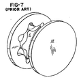
- Plates such as plate 18 in Figure 7 seal the chambers 3 and 12 in Figure 2, which are described below.
- rotor 6 rotates about center CA, as indicated by the arrow pointing to that center.
- Rotor R rotates about center CB, as indicated by the arrow.
- the distance between centers CA and CB is defined as the "eccentricity" of the two rotors.
- Figures 3 - 6 illustrate these two rotations.
- Figure 3 illustrates the starting position. Dots D1 and D2 have been added for reference.
- rotor 6 has been rotated counter-clockwise by the shaft (not shown) through about 20 degrees.
- the other rotor R is carried along, but not through a full 20 degrees (because the tooth ratio between the rotors is 6/7).
- Chamber CH1 has been reduced in volume, thereby causing fluid to become expelled through conduits which are not shown.
- pressurized fluid delivered to chambers such as CH1 forces the chambers to expand, thereby inducing rotation of both rotors 6 and R about their respective centers CA and CB.
- An object of the invention is to provide an improved cooling system for an automotive vehicle.
- a cooling system for an automotive vehicle is as specified in claim 1.
- Figure 8 illustrates one form of the invention, comprising an inner rotor IR, a ring rotor RR, and an outer rotor OR.
- Two gear sets, or sections, are present.
- the outer gear 33 of inner rotor IR and the inner gear 36 of ring rotor RR cooperate to form a first gear set S1, or first gerotor pair.
- the outer gear 27 of ring rotor RR and the inner gear 30 of outer rotor OR cooperate to form a second gear set S2, or second gerotor pair.
- Both gear sets are shown as one-tooth difference type, but that type is not considered essential.
- Each gear set operates as a separate, though linked, hydraulic motor, or pump, depending on the mode of operation chosen.
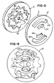
- a plate 37 contains ports HP1, HP2, LP1, and LP2, which deliver fluid to the two gear sets.
- Figure 9 illustrates the plate 37 in plan view.
- Two high-pressure ports, HP1 and HP2 deliver fluid to respective gear sets S1 and S2.
- Two low-pressure ports, LP1 and LP2, exhaust fluid from the respective gear sets S1 and S2.
- outer rotor OR rotates about center C1 in Figure 10, as indicated by the arrow pointing to C1.
- Ring rotor RR rotates about center C2
- inner rotor IR rotates about center C3, both as indicated by arrows.
- the ring rotor RR would be sized so that point P1 would contact point P2, and the contact would act as a seal. Similarly, point P3 would contact point P4, for the same reason. However, for ease of generating drawings, in order to show the rotation which will now be discussed, these points P1 and P3 are shown separated from points P2 and P4.
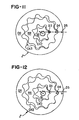
- Figure 11 illustrates the starting position. Pressurized fluid is injected into chambers CH2 and CH3, through the ports HP1 and HP2 in plate 37 in Figures 8 and 9.
- reference dots D3, D4, and D5 are added.
- the pressurized fluid causes all rotors to rotate about their respective centers shown in Figure 10, as the sequence of Figures 11 through 18 indicates.
- the ratios of rotation are in proportion to the tooth ratios, and are 6/7 and 10/11.
- the ring rotor RR undergoes 6 revolutions with respect to the inner rotor IR.
- the outer rotor RR undergoes 10 revolutions.
- a speed reduction occurs from inner rotor IR to outer rotor OR, in the ratio (6/7) x (10/11).
- Figure 19 is a schematic cross-sectional view of the apparatus of Figure 8.
- Wall 37 is not a flat plate, but contains fluid conduits, and other apparatus.
- the motor operates under two speed conditions, using a single pressure source (not shown), applied to line 50.
- displacement valve D is closed, thereby causing hydraulic fluid to be applied to port HP1 exclusively.
- Both rotors IR and OR rotate as shown in Figures 11 - 18, and at a relatively high speed and high pressure drop across the motor 2. This is called "single-displacement" mode.
- a check valve CK is used during single-displacement mode. At this time, gear set S2 in Figure 9 is not used as a motor, so that set operates as a pump.
- the check valve CK allows oil being pumped by set S2 to flow in a continuous loop from outlet LP2 to inlet HP2, and at low pressure.
- displacement valve D opens, based on a pressure differential sensed on lines L1 and L2 (or other measured parameter, such as engine speed, radiator fluid temperature, vehicle speed, and so on), and applies pressurized fluid to both ports HP1 and HP2.
- a pressure differential sensed on lines L1 and L2 or other measured parameter, such as engine speed, radiator fluid temperature, vehicle speed, and so on
- the same rotation occurs as shown in Figures 11 - 18, but now at a lower speed and with the same flow rate. That is, the same relative rotation of the three rotors IR, RR, and OR occurs, at the same ratio as before, namely, (6/7) and (10/11), but now at a lower speed, and lower pressure drop across the motor 2. This is called “dual-displacement" mode.
- Check valve CK is closed.
- the motor 2 in Figure 20 is used to drive a fan 55 to cool a radiator 58, used in an automotive vehicle 62. Pressure is applied by an engine-driven pump (not shown), and the pressure reaching the motor 2 is controlled by a regulator (also not shown). The regulator provides the desired pressure to the motor.
- a pump not shown
- the regulator provides the desired pressure to the motor.
- Such pumps and regulators are known in the art.
- the motor 2 can operate in either single or dual-displacement mode, depending on the cooling requirements.
- a high fan speed and pressure during dual displacement may be required, such as 3500 rpm at 1400 psi.
- the selection between low- and high-speed operation is, as explained above, determined by displacement valve D in Figure 19. That valve can be controlled by a signal on an input line IN. Alternately, the fluid supplied on line 50 can be provided by a hydraulic pump which is driven by the engine (not shown) of the vehicle 62. The flow on line 50 will be closely proportional to the speed of the engine.
- valve D is designed to remain closed, thereby providing high speed of motor 2.
- the pressure in line L1 will increase.
- the valve D opens, thereby providing low speed of motor 2.
- the motor 2 is designed such that, in dual-displacement mode, it displaces 9,83 l (0.6 cubic inch) per revolution, written as 9.83 l/rev (0.6 cu. in./rev). In single-displacement mode, it displaces 4.1 l/rev (0.25 cu. in./rev).
- the ratio of these two speeds is roughly two: 1848/770 or 2.4 to 1. If a fixed, single-displacement pump, of the prior art type, were used, then, to accomplish this change in speed, a corresponding change in displacement would be required. That is, if rotation at 770 rpm required two gallons per minute, then rotation at 1848 would require 2.4 x 7.57 l (2 gallons) per minute. The invention eliminates this requirement.
- the two gear sets S1 and S2 may be constructed of four distinct gears, as shown in Figures 21A and 21B.
- the gears 27 and 36 are not carried by a single ring rotor RR as in Figure 8, but take the form of separate gears RR2 and RR1 in Figures 21A and 21B, bottom.
- the axial thicknesses T1 and T2 of the two pairs are shown, and need not be the same.
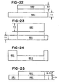
- gear RR2 is physically separate from gear RR1, and rests upon RR1 as indicated by the dashed lines in Figure 22.
- gear RR2 may occupy two axial regions, as shown in Figure 23.
- gear RR2 When inserted into gear RR1, gear RR2 may occupy the axial thickness T1, and also extend beyond T1 by the difference (T2 - T1), as shown in Figure 25.
- Inner gear RR2 may be constructed in a single piece, reducing the number of gears from four to three.
- these volumes are designed to be identical. In another embodiment, the volumes are 4.9 ml (0.3 cubic inch) between gears 27 and 30, and 3,28 ml (0.2 cubic inch) between gears 30 and 33.
- the volume between the inner gears 36 and 33 is larger than that between gears 27 and 30.
- the physically larger gerotor pair displaces a smaller volume.
- the invention of Figure 20 provides a significant savings in energy, compared with other approaches. For example, one set of calculations shows that, if motor 2 delivers about 5.2kW (7 horsepower), then about 10,4kW (14 horsepower) in hydraulic fluid is required to be delivered to motor 2. That is, the motor 2 consumes 14 horsepower, and delivers 5,2kW (7 horsepower), for an efficiency of 50 percent. The efficiency exceeds 40 percent.
- clutch fans driven by the engine are in widespread use to perform the function of motor 2. Many of them consume about 22,4 kW (30 horsepower), in order to deliver the same engine cooling capability. The efficiency is less than 25 percent.
- the pressure ratio HP1/LP1 need not be the same as the ratio HP2/LP2; the pressure ratios may be different. Further, the pressures at ports HP1 and HP2 may be different.
- the invention can be used either as a motor or a pump. In motor operation, fluid pressure is converted into torque. In pump operation, torque is converted into fluid pressure. In both cases, a transfer between pressure and torque occurs.
- gear set S1 in Figure 5 can act as a motor
- gear set S2 can act as a pump
- port HP2 becomes a low-pressure port
- port LP2 becomes a high-pressure port
- the invention should be distinguished from gear systems, such as planetary gear systems, which contain lubricants. Because of factors such as viscosity and other fluidic effects, the lubricant exerts some forces upon the gears, and the gears also exert forces upon the lubricant. It could be said that a transfer between pressure and torque occurs.
- the rotors IR, RR, and OR contain axial faces A, which face in the axial direction (as viewed in Figure 8), that is in the direction axis 51 extends.
- Plate 37 when assembled to the motor, has a face F which is parallel to, and adjacent, the axial faces A.
- Figure 10 shows two pairs of gears: pair 27 and 30, which have 10 and 11 teeth, respectively, and pair 33 and 36, which have 6 and 7 teeth respectively. The tooth difference in each pair is one.
- the rotors in Figure 8 are substantially coplanar, and rotate about centers which have eccentricity, with respect to each other.
- Gerotors are commercially available.
- Sumatomo Electric designs gerotor motors and pumps to meet specifications provided by a purchaser.
- the invention provides a "dual-displacement" hydraulic machine.
- “dual-displacement” is that, for a given machine speed, two selectable flow rates of fluid through the machine are available. Other definitions are possible.
Landscapes
- Engineering & Computer Science (AREA)
- Mechanical Engineering (AREA)
- General Engineering & Computer Science (AREA)
- Rotary Pumps (AREA)
- Hydraulic Motors (AREA)
- Details And Applications Of Rotary Liquid Pumps (AREA)
Description
- The invention concerns a cooling system for an automotive vehicle comprising a dual-rotor gerotor machine as specified in the preamble of
claim 1. Such a system is known from US-A-4189919. All rotors are placed in a single plane. This arrangement succeeds in placing the gerotors in a housing of small axial length, yet causing them to provide a large displacement of hydraulic fluid per revolution. This arrangement provides large horsepower in a small package. - Figure 1 illustrates a
hydraulic machine 2 of the gerotor type, found in the prior art. A shaft (not shown) engages splines 9, and rotatesrotor 6. Themachine 2 can operate either as a pump or motor, but since operation as a pump is perhaps easier to understand, the explanation will be framed in terms of a pump. Plates such asplate 18 in Figure 7 seal thechambers - In Figure 2,
rotor 6 rotates about center CA, as indicated by the arrow pointing to that center. Rotor R rotates about center CB, as indicated by the arrow. The distance between centers CA and CB is defined as the "eccentricity" of the two rotors. - Figures 3 - 6 illustrate these two rotations. Figure 3 illustrates the starting position. Dots D1 and D2 have been added for reference. In Figure 4,
rotor 6 has been rotated counter-clockwise by the shaft (not shown) through about 20 degrees. The other rotor R is carried along, but not through a full 20 degrees (because the tooth ratio between the rotors is 6/7). Chamber CH1 has been reduced in volume, thereby causing fluid to become expelled through conduits which are not shown. - In Figure 5,
rotor 6 has been further rotated another 20 degrees counter-clockwise. Rotor R is again carried along, but not the full 20 degrees, and chamber CH1 is further reduced in volume. - In Figure 6,
rotor 6 has been further rotated another 20 degrees, for a total of 60 degrees, compared with Figure 3. Rotor R is carried along, but, again, not by the full 20 degrees. Now a visible separation SEP between dots D1 and D2 begins to appear, indicating the lag of rotor R behindrotor 6. Chamber CH1 is almost compressed to zero volume. - When the machine operates as a motor, the opposite sequence occurs: pressurized fluid delivered to chambers such as CH1 forces the chambers to expand, thereby inducing rotation of both
rotors 6 and R about their respective centers CA and CB. - An object of the invention is to provide an improved cooling system for an automotive vehicle.
- In one form of the invention, a cooling system for an automotive vehicle is as specified in
claim 1. -
- Figures 1 and 2 illustrate a prior-art
hydraulic machine 2, of the internal gear, one-tooth difference type. - Figures 3 - 6 illustrate a sequence of events occurring during rotation of
motor 2 of Figure 1. - Figure 7 is a prior art figure illustrating a
wall 18, which is part of a housing (not shown) containing themotor 2. - Figure 8 illustrates one form of the invention.
- Figure 9 is a plan view of one form of the invention.
- Figure 10 illustrates centers C1, C2, and C3, about which respective rotors OR, RR, and IR rotate.
- Figures 11 - 18 illustrate a sequence of events occurring during rotation of the invention.
- Figure 19 is a cross-sectional schematic view of the invention of Figure 10.
- Figure 20 illustrates one embodiment of the invention, wherein
block 58 represents a radiator in a motor vehicle. - Figure 21A illustrates another form of the invention;
- Figure 21B is a view taken along the
line 21B-21A in Figure 21B; - Figures 22 - 25 illustrate other forms of the invention; and
- Figure 26 illustrates another form of the invention.
- Figure 8 illustrates one form of the invention, comprising an inner rotor IR, a ring rotor RR, and an outer rotor OR. Two gear sets, or sections, are present. The
outer gear 33 of inner rotor IR and theinner gear 36 of ring rotor RR cooperate to form a first gear set S1, or first gerotor pair. Theouter gear 27 of ring rotor RR and theinner gear 30 of outer rotor OR cooperate to form a second gear set S2, or second gerotor pair. - Both gear sets are shown as one-tooth difference type, but that type is not considered essential. Each gear set operates as a separate, though linked, hydraulic motor, or pump, depending on the mode of operation chosen.
- A
plate 37 contains ports HP1, HP2, LP1, and LP2, which deliver fluid to the two gear sets. Figure 9 illustrates theplate 37 in plan view. Two high-pressure ports, HP1 and HP2, deliver fluid to respective gear sets S1 and S2. Two low-pressure ports, LP1 and LP2, exhaust fluid from the respective gear sets S1 and S2. - In operation, outer rotor OR rotates about center C1 in Figure 10, as indicated by the arrow pointing to C1. Ring rotor RR rotates about center C2, and inner rotor IR rotates about center C3, both as indicated by arrows.
- In actuality, the ring rotor RR would be sized so that point P1 would contact point P2, and the contact would act as a seal. Similarly, point P3 would contact point P4, for the same reason. However, for ease of generating drawings, in order to show the rotation which will now be discussed, these points P1 and P3 are shown separated from points P2 and P4.
- Operation as a motor will now be explained. Figure 11 illustrates the starting position. Pressurized fluid is injected into chambers CH2 and CH3, through the ports HP1 and HP2 in
plate 37 in Figures 8 and 9. In Figure 11, reference dots D3, D4, and D5 are added. - The pressurized fluid causes all rotors to rotate about their respective centers shown in Figure 10, as the sequence of Figures 11 through 18 indicates. The ratios of rotation are in proportion to the tooth ratios, and are 6/7 and 10/11. Thus, for every 7 revolutions of inner rotor IR, the ring rotor RR undergoes 6 revolutions with respect to the inner rotor IR. Similarly, for every 11 revolutions of ring rotor RR, the outer rotor RR undergoes 10 revolutions. Overall, a speed reduction occurs from inner rotor IR to outer rotor OR, in the ratio (6/7) x (10/11).
- Figure 19 is a schematic cross-sectional view of the apparatus of Figure 8.
Wall 37 is not a flat plate, but contains fluid conduits, and other apparatus. The motor operates under two speed conditions, using a single pressure source (not shown), applied toline 50. For high speed of shaft SH, displacement valve D is closed, thereby causing hydraulic fluid to be applied to port HP1 exclusively. Both rotors IR and OR rotate as shown in Figures 11 - 18, and at a relatively high speed and high pressure drop across themotor 2. This is called "single-displacement" mode. - A check valve CK is used during single-displacement mode. At this time, gear set S2 in Figure 9 is not used as a motor, so that set operates as a pump. The check valve CK allows oil being pumped by set S2 to flow in a continuous loop from outlet LP2 to inlet HP2, and at low pressure.
- For relatively low speed of shaft SH, displacement valve D opens, based on a pressure differential sensed on lines L1 and L2 (or other measured parameter, such as engine speed, radiator fluid temperature, vehicle speed, and so on), and applies pressurized fluid to both ports HP1 and HP2. The same rotation occurs as shown in Figures 11 - 18, but now at a lower speed and with the same flow rate. That is, the same relative rotation of the three rotors IR, RR, and OR occurs, at the same ratio as before, namely, (6/7) and (10/11), but now at a lower speed, and lower pressure drop across the
motor 2. This is called "dual-displacement" mode. Check valve CK is closed. - In one embodiment, the
motor 2 in Figure 20 is used to drive afan 55 to cool aradiator 58, used in anautomotive vehicle 62. Pressure is applied by an engine-driven pump (not shown), and the pressure reaching themotor 2 is controlled by a regulator (also not shown). The regulator provides the desired pressure to the motor. Such pumps and regulators are known in the art. - At low engine speeds, as in slow traffic, large cooling from
fan 55 is required, so single-displacement mode is used, to provide high-speed operation ofmotor 2, at relatively high fluid pressure. At high engine speeds, as in highway driving, incoming ram air is sufficient to cool theradiator 58, so that low-speed operation ofmotor 2 is desired. Dual-displacement mode is used, to provide low-speed operation ofmotor 2, at relatively low fluid pressure. - Other modes of operation are contemplated. For example, at engine idling speeds, the
motor 2 can operate in either single or dual-displacement mode, depending on the cooling requirements. As another example, when the vehicle tows a trailer, a high fan speed and pressure during dual displacement may be required, such as 3500 rpm at 1400 psi. - The selection between low- and high-speed operation is, as explained above, determined by displacement valve D in Figure 19. That valve can be controlled by a signal on an input line IN. Alternately, the fluid supplied on
line 50 can be provided by a hydraulic pump which is driven by the engine (not shown) of thevehicle 62. The flow online 50 will be closely proportional to the speed of the engine. - Thus, at low engine speeds, the valve D is designed to remain closed, thereby providing high speed of
motor 2. As engine speed increases, the pressure in line L1 will increase. When the differential reaches a threshold, the valve D opens, thereby providing low speed ofmotor 2. - It should be understood that the preceding discussion illustrates a specific embodiment of the invention, and that other modes of operation can be , implemented within the scope of the appended claims.
- Two examples of the two modes of operation are the following. The
motor 2 is designed such that, in dual-displacement mode, it displaces 9,83 l (0.6 cubic inch) per revolution, written as 9.83 l/rev (0.6 cu. in./rev). In single-displacement mode, it displaces 4.1 l/rev (0.25 cu. in./rev). - One gallon of fluid occupies 3,785 l (231 cubic inches). Thus, two gallons occupy 7,57 l (462 cubic inches). For the
motor 2 to consume 7,57 l (two gallons) per minute in single-displacement mode, 1848 revolutions per minute (rpm) are required: 462/0.25 = 1848. For themotor 2 to consume the same 7,57 l (two gallons) in dual-displacement mode, 770 rpm are required: 462/0.60 = 770. - Thus, for a given flow rate, two speeds are possible, by selecting between single- and dual-displacement modes. Further, in each mode, modulation is possible, by modulating the pressure applied to the motor.
- The ratio of these two speeds is roughly two: 1848/770 or 2.4 to 1. If a fixed, single-displacement pump, of the prior art type, were used, then, to accomplish this change in speed, a corresponding change in displacement would be required. That is, if rotation at 770 rpm required two gallons per minute, then rotation at 1848 would require 2.4 x 7.57 l (2 gallons) per minute. The invention eliminates this requirement.
- It is a fact that, in
motor 2, torque produced equals displacement*pressure/constant, where the constant is 75.4 (for units in lb.ft, cu.in/rev and psi). Adding units:
- dual: 0.6 * 1,000/75.4 = 10,8 Nm (7.95 lb. ft).
- single: 0.25 * 1,000/75.4 = 4,5 Nm (3.31 lb. ft).
- The two gear sets S1 and S2 may be constructed of four distinct gears, as shown in Figures 21A and 21B. The
gears - For example, in Figure 22, the gear RR2 is physically separate from gear RR1, and rests upon RR1 as indicated by the dashed lines in Figure 22.
Alternately, gear RR2 may occupy two axial regions, as shown in Figure 23. When inserted into gear RR1, gear RR2 may occupy the axial thickness T1, and also extend beyond T1 by the difference (T2 - T1), as shown in Figure 25. - It may be desirable to make gear RR1 thicker than RR2, as shown in Figure 24.
- Inner gear RR2 may be constructed in a single piece, reducing the number of gears from four to three.
- 1. The volume between the pair of
gears gears - In one embodiment, these volumes are designed to be identical. In another embodiment, the volumes are 4.9 ml (0.3 cubic inch) between
gears gears - In another embodiment, the volume between the
inner gears gears - 2. The invention of Figure 20 provides a significant savings in energy, compared with other approaches. For example, one set of calculations shows that, if
motor 2 delivers about 5.2kW (7 horsepower), then about 10,4kW (14 horsepower) in hydraulic fluid is required to be delivered tomotor 2. That is, themotor 2 consumes 14 horsepower, and delivers 5,2kW (7 horsepower), for an efficiency of 50 percent. The efficiency exceeds 40 percent. - In contrast, clutch fans driven by the engine (not shown) are in widespread use to perform the function of
motor 2. Many of them consume about 22,4 kW (30 horsepower), in order to deliver the same engine cooling capability. The efficiency is less than 25 percent. - 3. The pressure ratio HP1/LP1 need not be the same as the ratio HP2/LP2; the pressure ratios may be different. Further, the pressures at ports HP1 and HP2 may be different.
- 4. The invention can be used either as a motor or a pump. In motor operation, fluid pressure is converted into torque. In pump operation, torque is converted into fluid pressure. In both cases, a transfer between pressure and torque occurs.
- In addition, in some instances, dual operation can occur. For example, gear set S1 in Figure 5 can act as a motor, and gear set S2 can act as a pump. In this case, port HP2 becomes a low-pressure port, and port LP2 becomes a high-pressure port.
- The invention should be distinguished from gear systems, such as planetary gear systems, which contain lubricants. Because of factors such as viscosity and other fluidic effects, the lubricant exerts some forces upon the gears, and the gears also exert forces upon the lubricant. It could be said that a transfer between pressure and torque occurs.
- However, any transfer of this type is of minor significance. No significant conversion between torque and these pressures occurs. "Significant" refers to a conversion rate exceeding 25 percent, so that, for example, over 25 percent of the energy contained in a given volume of fluid is converted into torque.
- 5. In Figure 8, the rotors IR, RR, and OR contain axial faces A, which face in the axial direction (as viewed in Figure 8), that is in the
direction axis 51 extends.Plate 37, when assembled to the motor, has a face F which is parallel to, and adjacent, the axial faces A. - 6. Figure 10 shows two pairs of gears:
pair pair - 7. The rotors in Figure 8 are substantially coplanar, and rotate about centers which have eccentricity, with respect to each other.
- 8. Gerotors are commercially available. The following U.S. patents, assigned to Sumatomo Electric Company of Japan, describe approaches to designing gerotors: 4,504,202, 4,673,342, 4,657,492, 4,518,332. In addition, Sumatomo Electric designs gerotor motors and pumps to meet specifications provided by a purchaser.
- 9. The invention provides a "dual-displacement" hydraulic machine. One definition of "dual-displacement" is that, for a given machine speed, two selectable flow rates of fluid through the machine are available. Other definitions are possible.
- 10. During both single and dual-displacement operation, the speed of
motor 2 is infinitely variable between its minimum and maximum limits.
Claims (10)
- A cooling system for an automotive vehicle, comprising:a fan (55) and a hydraulic motor (2) driving the fan and comprising a first gerotor (33,36);characterised in that said hydraulic motor (2) driving the fan is a dual-displacement hydraulic motor comprising a displacement valve (D) for selecting said dual-displacement hydraulic motor between:i) a low-displacement mode in which a given flow rate causes a relatively high motor speed; andii) a high-displacement mode in which the given flow rate causes a relatively low motor speed;said dual displacement hydraulic motor further comprising:a second gerotor (27,30) that is substantially coplanar with said first gerotor, said first and second gerotors being coupled to a common drive shaft (54) that is coupled to said fan (55):said first gerotor (33,36) rotating about a first axis and said second gerotor rotating about a second axis, wherein said first axis is offset from said second axis;herein said displacement valve (D) controls hydraulic fluid in said hydraulic motor to select between one of said first or second gerotors to both of said first and second gerotors when it is desired to drive said fan between said relatively high motor speed and said relatively low motor speed, respectively.
- System according to claim 1, and further comprising means for selectively adjusting pressure or flow delivered to the motor in each mode.
- The cooling system as recited in claim 1 wherein said system further comprises:a regulator for modulating the pressure applied to said dual-displacement hydraulic motor.
- The cooling system as recited in claim 1 wherein said first gerotor (33,36) comprises
a first thickness and said second gerotor (27,30) comprises a second thickness; said first and second thickness being the same. - The cooling system as recited in claim 1 wherein said first gerotor comprises
a first thickness and said second gerotor comprises a second thickness; said first and second thickness being different. - The cooling system as recited in claim 1 wherein said displacement valve (D) directs fluid to either one or both of said first and second gerotors when high or low cooling, respectively, by said fan is desired.
- The cooling system as recited in claim 1 wherein said first and second gerotors comprise three distinct gears.
- The cooling system as recited in claim 1 wherein said first and second gerotors comprise four distinct gears (27,30,33,36).
- The cooling system as recited in claim 1 wherein said dual displacement hydraulic motor generates at least 10,8 Nm (7.95 lb. ft.) torque during said high-displacement mode.
- The cooling system as recited in claim 1 wherein said dual displacement hydraulic motor generates at least 0,5 Nm (3.31 lb. ft.) torque during said low-displacement mode.
Applications Claiming Priority (3)
| Application Number | Priority Date | Filing Date | Title |
|---|---|---|---|
| US09/231,344 US6195990B1 (en) | 1999-01-13 | 1999-01-13 | Hydraulic machine comprising dual gerotors |
| US231344 | 1999-01-13 | ||
| PCT/US2000/000774 WO2000042321A1 (en) | 1999-01-13 | 2000-01-12 | Hydraulic machine comprising dual gerotors |
Publications (3)
| Publication Number | Publication Date |
|---|---|
| EP1144868A1 EP1144868A1 (en) | 2001-10-17 |
| EP1144868B1 EP1144868B1 (en) | 2005-11-09 |
| EP1144868B9 true EP1144868B9 (en) | 2006-05-03 |
Family
ID=22868839
Family Applications (1)
| Application Number | Title | Priority Date | Filing Date |
|---|---|---|---|
| EP00904315A Expired - Lifetime EP1144868B9 (en) | 1999-01-13 | 2000-01-12 | Hydraulic machine comprising dual gerotors |
Country Status (5)
| Country | Link |
|---|---|
| US (1) | US6195990B1 (en) |
| EP (1) | EP1144868B9 (en) |
| JP (1) | JP2002535538A (en) |
| DE (1) | DE60023839T2 (en) |
| WO (1) | WO2000042321A1 (en) |
Families Citing this family (22)
| Publication number | Priority date | Publication date | Assignee | Title |
|---|---|---|---|---|
| US6386836B1 (en) * | 2000-01-20 | 2002-05-14 | Eagle-Picher Industries, Inc. | Dual gerotor pump for use with automatic transmission |
| US6612822B2 (en) * | 2001-07-09 | 2003-09-02 | Valeo Electrical Systems, Inc. | Hydraulic motor system |
| DE10159147A1 (en) * | 2001-12-01 | 2003-06-18 | Zahnradfabrik Friedrichshafen | Hydraulic gear pump has pump stages in one plane, one above other radially |
| ATE318374T1 (en) * | 2002-07-17 | 2006-03-15 | Elthom Entpr Ltd | ROTATING SCREW MACHINE AND METHOD FOR CONVERTING MOVEMENT IN SUCH MACHINE |
| US6743005B1 (en) | 2002-12-26 | 2004-06-01 | Valeo Electrical Systems, Inc. | Gerotor apparatus with balance grooves |
| WO2005005836A1 (en) * | 2003-07-14 | 2005-01-20 | Elthom Enterprises Limited | Volume screw machine of rotary type |
| DE202004004231U1 (en) * | 2004-03-17 | 2005-07-28 | Härle, Hermann | Volumetric flow variable displacement pump |
| DE102005014654B4 (en) * | 2005-03-31 | 2014-03-06 | Gkn Driveline International Gmbh | Motor vehicle hydraulic pump |
| US7614227B2 (en) | 2006-08-04 | 2009-11-10 | Briggs And Stratton Corporation | Rotary control valve for a hydrostatic transmission |
| US7739870B2 (en) | 2006-08-04 | 2010-06-22 | Briggs And Stratton Corporation | Hydrostatic transmission |
| US20130213023A1 (en) * | 2012-02-22 | 2013-08-22 | Peter K. Eckstein | Hydraulic system having low-speed operating mode |
| US20130236345A1 (en) * | 2012-03-07 | 2013-09-12 | Gobee KIM | Compressor unit including gear rotor and compressor system using the same |
| US20130236346A1 (en) * | 2012-03-07 | 2013-09-12 | Gobee KIM | Two step compressor unit and compressor system having the same |
| US9366272B2 (en) | 2013-08-09 | 2016-06-14 | Caterpillar Inc. | Hydraulic system having low speed operation |
| GB201401998D0 (en) * | 2014-02-05 | 2014-03-19 | Forum Energy Technologies Uk Ltd | Torque tool,motor assembly and methods of use |
| KR101573662B1 (en) * | 2015-06-30 | 2015-12-01 | 김고비 | Rotating type fluid machinery and system havine the same |
| AU2018322191B2 (en) | 2017-08-21 | 2023-10-05 | Macnaught Pty Ltd | Reel braking system |
| US10731735B1 (en) * | 2018-03-19 | 2020-08-04 | Mainstream Engineering Corporation | Power transfer system and method using a variable speed ratio regulating device |
| DE202020105313U1 (en) | 2020-09-16 | 2021-12-21 | Vogelsang Gmbh & Co. Kg | Two-speed gerotor motor |
| DE102021133555A1 (en) | 2021-12-16 | 2023-06-22 | Endter SinterTechnics GmbH & Co. KG | Gerotor unit and pump or motor with a gerotor unit |
| DE102022202358A1 (en) | 2022-03-09 | 2023-09-14 | Mahle International Gmbh | Gerotor device and pump device with gerotor device |
| DE102022207938A1 (en) | 2022-08-01 | 2024-02-01 | Mahle International Gmbh | Water pump for a motor vehicle cooling system |
Family Cites Families (22)
| Publication number | Priority date | Publication date | Assignee | Title |
|---|---|---|---|---|
| US1389189A (en) * | 1919-06-10 | 1921-08-30 | Feuerheerd Ernest | Rotary motor or pump |
| US1968113A (en) * | 1930-08-02 | 1934-07-31 | Comstock & Wescott | Rotary engine or the like |
| US3547565A (en) | 1967-07-21 | 1970-12-15 | Reliance Electric Co | Rotary device |
| US3910733A (en) * | 1969-09-18 | 1975-10-07 | Leslie H Grove | Rotary mechanism having at least two camming elements |
| US4189919A (en) * | 1978-05-18 | 1980-02-26 | Eaton Corporation | Motor-valve apparatus for hydraulic fan drive system |
| GB2062187B (en) * | 1979-11-06 | 1983-04-13 | Hammond Eng Ltd | Hydrostatic transmission unit |
| JPS5870014A (en) | 1981-10-22 | 1983-04-26 | Sumitomo Electric Ind Ltd | oil pump |
| GB2110759A (en) * | 1981-11-27 | 1983-06-22 | Concentric Pumps Ltd | Rotary positive-displacement fluid-machines |
| JPS5920591A (en) | 1982-07-23 | 1984-02-02 | Sumitomo Electric Ind Ltd | Sintered rotor for rotary pump and method of manufacturing thereof |
| JPS5979083A (en) | 1982-10-27 | 1984-05-08 | Sumitomo Electric Ind Ltd | Rotary pump rotor |
| US4658583A (en) * | 1984-06-11 | 1987-04-21 | Trw Inc. | Double staged, internal rotary pump with flow control |
| DE3432704A1 (en) * | 1984-09-06 | 1986-03-13 | Adam Opel AG, 6090 Rüsselsheim | Eaton pump |
| US4639202A (en) | 1985-02-06 | 1987-01-27 | Mahanay Joseph W | Gerotor device with dual valving plates |
| JPS6220682A (en) * | 1985-07-18 | 1987-01-29 | Honda Motor Co Ltd | compound tooth pump |
| GB8520351D0 (en) | 1985-08-14 | 1985-09-18 | Concentric Pumps Ltd | Transmission coupling |
| DE4141492C2 (en) * | 1991-12-16 | 2000-08-10 | Mannesmann Rexroth Ag | Hydraulic arrangement for work machines |
| US5165377A (en) * | 1992-01-13 | 1992-11-24 | Caterpillar Inc. | Hydraulic fan drive system |
| US5561978A (en) | 1994-11-17 | 1996-10-08 | Itt Automotive Electrical Systems, Inc. | Hydraulic motor system |
| US5960628A (en) * | 1995-03-09 | 1999-10-05 | Valeo Electrical Systems, Inc. | Hydraulically powered fan and power steering in vehicle |
| US5535845A (en) | 1995-03-09 | 1996-07-16 | Itt Automotive Electrical Systems, Inc. | Automotive hydraulic system and method |
| DE29521598U1 (en) | 1995-07-31 | 1998-01-22 | Voulgaris, Alexander, 83734 Hausham | Hydraulic machine in toothed ring design |
| DE19622688A1 (en) | 1996-06-05 | 1997-12-11 | Bayerische Motoren Werke Ag | Internal combustion engine with separate hydraulic circuits supplied with lubricating oil |
-
1999
- 1999-01-13 US US09/231,344 patent/US6195990B1/en not_active Expired - Lifetime
-
2000
- 2000-01-12 DE DE60023839T patent/DE60023839T2/en not_active Expired - Lifetime
- 2000-01-12 JP JP2000593863A patent/JP2002535538A/en active Pending
- 2000-01-12 WO PCT/US2000/000774 patent/WO2000042321A1/en not_active Ceased
- 2000-01-12 EP EP00904315A patent/EP1144868B9/en not_active Expired - Lifetime
Also Published As
| Publication number | Publication date |
|---|---|
| EP1144868B1 (en) | 2005-11-09 |
| WO2000042321A1 (en) | 2000-07-20 |
| US6195990B1 (en) | 2001-03-06 |
| EP1144868A1 (en) | 2001-10-17 |
| JP2002535538A (en) | 2002-10-22 |
| DE60023839D1 (en) | 2005-12-15 |
| DE60023839T2 (en) | 2006-07-27 |
Similar Documents
| Publication | Publication Date | Title |
|---|---|---|
| EP1144868B1 (en) | Hydraulic machine comprising dual gerotors | |
| US5687568A (en) | Hydraulic motor system | |
| US8128377B2 (en) | Split-pressure dual pump hydraulic fluid supply system for a multi-speed transmission and method | |
| CA3035635C (en) | Dual input pump and system | |
| US3807912A (en) | Fluid flow device having high degree of flexibility | |
| US6332522B1 (en) | Hydraulic coupling for vehicle drivetrain | |
| CN1043366A (en) | Rotary positive displacement pumps or motors and their use | |
| WO2001051870B1 (en) | Hydraulic hybrid vehicle | |
| CN1263971C (en) | Lubrication pump for inter-axle differential | |
| CA2549910C (en) | Pressurized hydraulic fluid system with remote charge pump | |
| WO2010041120A2 (en) | High efficiency supercharger outlet | |
| JPH05263770A (en) | Oil pump | |
| US3995978A (en) | Hydraulic fluid pressure device and porting arrangement therefor | |
| EP0207687B1 (en) | Rotary fluid pressure device having free-wheeling capability | |
| JP2001289315A (en) | Automatic transmission for automobile | |
| JP4564494B2 (en) | Double or double pump | |
| US4669267A (en) | Hydrostatic hydraulic transmission | |
| CA2229056C (en) | Three stage self-regulating gerotor pump | |
| CA1166933A (en) | Drive transmission means | |
| US3200590A (en) | Transmission mechanism | |
| JP5001162B2 (en) | Hydraulic mechanical transmission | |
| EP0660000A1 (en) | Positive displacement pumps | |
| JPS62218680A (en) | Compressor | |
| JPH06144069A (en) | Hydraulic driving device of auxiliary equipment for vehicle | |
| JPS58102849A (en) | Hydrulic-mechanical type change gear |
Legal Events
| Date | Code | Title | Description |
|---|---|---|---|
| PUAI | Public reference made under article 153(3) epc to a published international application that has entered the european phase |
Free format text: ORIGINAL CODE: 0009012 |
|
| 17P | Request for examination filed |
Effective date: 20010712 |
|
| AK | Designated contracting states |
Kind code of ref document: A1 Designated state(s): AT BE CH CY DE DK ES FI FR GB GR IE IT LI LU MC NL PT SE |
|
| RIN1 | Information on inventor provided before grant (corrected) |
Inventor name: HILL, JOHN, S. Inventor name: MACHESNEY, KERRY, A. Inventor name: MIENTUS, MICHAEL, J. |
|
| RBV | Designated contracting states (corrected) |
Designated state(s): DE ES FR GB IT |
|
| GRAP | Despatch of communication of intention to grant a patent |
Free format text: ORIGINAL CODE: EPIDOSNIGR1 |
|
| GRAS | Grant fee paid |
Free format text: ORIGINAL CODE: EPIDOSNIGR3 |
|
| GRAA | (expected) grant |
Free format text: ORIGINAL CODE: 0009210 |
|
| AK | Designated contracting states |
Kind code of ref document: B1 Designated state(s): DE ES FR GB IT |
|
| PG25 | Lapsed in a contracting state [announced via postgrant information from national office to epo] |
Ref country code: IT Free format text: LAPSE BECAUSE OF FAILURE TO SUBMIT A TRANSLATION OF THE DESCRIPTION OR TO PAY THE FEE WITHIN THE PRESCRIBED TIME-LIMIT;WARNING: LAPSES OF ITALIAN PATENTS WITH EFFECTIVE DATE BEFORE 2007 MAY HAVE OCCURRED AT ANY TIME BEFORE 2007. THE CORRECT EFFECTIVE DATE MAY BE DIFFERENT FROM THE ONE RECORDED. Effective date: 20051109 |
|
| REG | Reference to a national code |
Ref country code: GB Ref legal event code: FG4D |
|
| REF | Corresponds to: |
Ref document number: 60023839 Country of ref document: DE Date of ref document: 20051215 Kind code of ref document: P |
|
| PG25 | Lapsed in a contracting state [announced via postgrant information from national office to epo] |
Ref country code: GB Free format text: LAPSE BECAUSE OF NON-PAYMENT OF DUE FEES Effective date: 20060209 |
|
| PG25 | Lapsed in a contracting state [announced via postgrant information from national office to epo] |
Ref country code: ES Free format text: LAPSE BECAUSE OF FAILURE TO SUBMIT A TRANSLATION OF THE DESCRIPTION OR TO PAY THE FEE WITHIN THE PRESCRIBED TIME-LIMIT Effective date: 20060220 |
|
| PLBE | No opposition filed within time limit |
Free format text: ORIGINAL CODE: 0009261 |
|
| STAA | Information on the status of an ep patent application or granted ep patent |
Free format text: STATUS: NO OPPOSITION FILED WITHIN TIME LIMIT |
|
| 26N | No opposition filed |
Effective date: 20060810 |
|
| PG25 | Lapsed in a contracting state [announced via postgrant information from national office to epo] |
Ref country code: FR Free format text: LAPSE BECAUSE OF FAILURE TO SUBMIT A TRANSLATION OF THE DESCRIPTION OR TO PAY THE FEE WITHIN THE PRESCRIBED TIME-LIMIT Effective date: 20061020 |
|
| GBPC | Gb: european patent ceased through non-payment of renewal fee |
Effective date: 20060209 |
|
| EN | Fr: translation not filed | ||
| PG25 | Lapsed in a contracting state [announced via postgrant information from national office to epo] |
Ref country code: FR Free format text: LAPSE BECAUSE OF FAILURE TO SUBMIT A TRANSLATION OF THE DESCRIPTION OR TO PAY THE FEE WITHIN THE PRESCRIBED TIME-LIMIT Effective date: 20051109 |
|
| PGFP | Annual fee paid to national office [announced via postgrant information from national office to epo] |
Ref country code: DE Payment date: 20180111 Year of fee payment: 19 |
|
| REG | Reference to a national code |
Ref country code: DE Ref legal event code: R119 Ref document number: 60023839 Country of ref document: DE |
|
| PG25 | Lapsed in a contracting state [announced via postgrant information from national office to epo] |
Ref country code: DE Free format text: LAPSE BECAUSE OF NON-PAYMENT OF DUE FEES Effective date: 20190801 |