EP1143873B1 - Selective dentin caries excavator - Google Patents
Selective dentin caries excavator Download PDFInfo
- Publication number
- EP1143873B1 EP1143873B1 EP99960601A EP99960601A EP1143873B1 EP 1143873 B1 EP1143873 B1 EP 1143873B1 EP 99960601 A EP99960601 A EP 99960601A EP 99960601 A EP99960601 A EP 99960601A EP 1143873 B1 EP1143873 B1 EP 1143873B1
- Authority
- EP
- European Patent Office
- Prior art keywords
- bur
- cutting elements
- dental
- blades
- dental bur
- Prior art date
- Legal status (The legal status is an assumption and is not a legal conclusion. Google has not performed a legal analysis and makes no representation as to the accuracy of the status listed.)
- Expired - Lifetime
Links
- 201000009241 dentin caries Diseases 0.000 title 1
- 238000005520 cutting process Methods 0.000 claims abstract description 42
- 239000000463 material Substances 0.000 claims abstract description 31
- 208000002925 dental caries Diseases 0.000 claims abstract description 17
- 239000000919 ceramic Substances 0.000 claims abstract description 9
- 239000004033 plastic Substances 0.000 claims abstract description 5
- 229920003023 plastic Polymers 0.000 claims abstract description 5
- 229910052751 metal Inorganic materials 0.000 claims abstract description 4
- 239000002184 metal Substances 0.000 claims abstract description 4
- 210000004268 dentin Anatomy 0.000 claims description 12
- 229910052782 aluminium Inorganic materials 0.000 claims description 7
- XAGFODPZIPBFFR-UHFFFAOYSA-N aluminium Chemical compound [Al] XAGFODPZIPBFFR-UHFFFAOYSA-N 0.000 claims description 7
- 238000005553 drilling Methods 0.000 claims description 7
- 229910000838 Al alloy Inorganic materials 0.000 claims description 6
- 239000004411 aluminium Substances 0.000 claims 2
- 230000000717 retained effect Effects 0.000 claims 1
- 238000013461 design Methods 0.000 description 11
- 229920002379 silicone rubber Polymers 0.000 description 4
- 238000010276 construction Methods 0.000 description 3
- 230000000694 effects Effects 0.000 description 3
- 239000002991 molded plastic Substances 0.000 description 3
- 229920000642 polymer Polymers 0.000 description 3
- 239000004945 silicone rubber Substances 0.000 description 3
- 210000002268 wool Anatomy 0.000 description 3
- 238000013459 approach Methods 0.000 description 2
- 230000003247 decreasing effect Effects 0.000 description 2
- 239000007924 injection Substances 0.000 description 2
- 238000002347 injection Methods 0.000 description 2
- 239000011148 porous material Substances 0.000 description 2
- 241000721080 Echinodorus Species 0.000 description 1
- 239000004944 Liquid Silicone Rubber Substances 0.000 description 1
- 229910000831 Steel Inorganic materials 0.000 description 1
- 238000005299 abrasion Methods 0.000 description 1
- 229910045601 alloy Inorganic materials 0.000 description 1
- 239000000956 alloy Substances 0.000 description 1
- 238000005452 bending Methods 0.000 description 1
- 229910010293 ceramic material Inorganic materials 0.000 description 1
- 230000008878 coupling Effects 0.000 description 1
- 238000010168 coupling process Methods 0.000 description 1
- 238000005859 coupling reaction Methods 0.000 description 1
- 230000007547 defect Effects 0.000 description 1
- 238000011161 development Methods 0.000 description 1
- 239000006260 foam Substances 0.000 description 1
- 238000007373 indentation Methods 0.000 description 1
- 238000003754 machining Methods 0.000 description 1
- 238000012986 modification Methods 0.000 description 1
- 230000004048 modification Effects 0.000 description 1
- 229920003229 poly(methyl methacrylate) Polymers 0.000 description 1
- 239000004926 polymethyl methacrylate Substances 0.000 description 1
- 239000010959 steel Substances 0.000 description 1
Images


Classifications
-
- A—HUMAN NECESSITIES
- A61—MEDICAL OR VETERINARY SCIENCE; HYGIENE
- A61C—DENTISTRY; APPARATUS OR METHODS FOR ORAL OR DENTAL HYGIENE
- A61C3/00—Dental tools or instruments
- A61C3/02—Tooth drilling or cutting instruments; Instruments acting like a sandblast machine
Definitions
- This invention relates generally to the field of dental cutting tools, and more specifically to a dental bur that selectively removes carious dentin without removing healthy dentin.
- DE 298 10 111 U1 relates to a medical or dental instrument with a tool holder to those front end a tool with a tool shaft and a working body arranged on it is connected detachably by a holding device to tool holder, wherein the tool can be moved by a drive to perform its working movement, or tool for such instrument.
- the dental cutting tool (or "bur") of the present invention has a working surface that includes cutting elements adapted to cut or drill selectively only material of less than a preselected hardness. When material above the preselected level of hardness is encountered, the cutting elements deflect, deform, or abrade, thus preventing damage to the harder non-carious dentin.
- Figs. 1 and 1A are side and sectional views, respectively, of the cutting head of a bur according to the first exemplary embodiment of the present invention.
- bur 210 includes bur blades 220 interposed between grooves 230. Bur blades 220 are formed so that they will cut soft carious dentin, but will bend inward into the space of grooves 230 upon reaching a dentin of a specified hardness and render bur 210 temporarily or permanently inoperable.
- blades 220 may include concavity 225 to effect better control of the deflection, deformation, and/or abrasion of blades 220 upon encountering a resistant force above a preselected level, characteristic of the maximum force needed to cut carious dentin, without cutting healthy dentin.
- a resistant force above a preselected level characteristic of the maximum force needed to cut carious dentin, without cutting healthy dentin.
- KHN Knoop Hardness Number
- the blades (or cutting elements in other embodiments) of the present invention would be constructed so as to deflect, deform, or abrade upon encountering material above a preselected hardness, preferably above 60 KHN.
- blades 220 so as to deflect at the preselected resistant force by proper selection of the material of construction of blades 220, and the dimensions thereof, particularly the height of each blade and the varying width of each blade.
- concavities 225 can be incorporated into the design of the blades 220 to optimize deflection or deformation.
- the number of bur blades 220 can be increased or reduced according to design parameters.
- the depth of grooves 230 can be varied and the surface area of bur blades 220 can be increased or decreased according to specific design parameters.
- the number of bur blades 220 can be reduced and grooves 230 can be deepened to increase the scooping effect in soft dentin, and to decrease the efficiency of bur blades 220 as the bur approaches harder material.
- concavity 225 the slope and depth of which may vary considerably.
- an angular indentation may also perform this deflection-effecting function (i.e., to control the resistance level at which bur blade 220 will defect).
- bur blades 220 can recover to their initial shape after bending back into grooves 230 and may be available then to cut more superficial, softer carious dentin. These include silicone rubber and resilient, molded plastic embodiments. The ability to recover allows for removal of carious dentin by multiple vertical approaches. In other alternative embodiments of bur 210, constructed of aluminum, aluminum alloy, hard ceramic, and plastic, blades 220 will deform or abrade and be rendered inoperable.
- blades 220 and grooves 230 may be better seen from the cross sectional view of bur 210 in Fig. 1A .
- Bur 210 may be manufactured by machining a relatively hard metal sphere, such as one comprised of aluminum or aluminum alloy.
- blades 220 may be separately formed and secured to an underlying base. In either case, blades 220 may be anchored through a shank to a central pin extending through blades 220 and the core.
- the shank is standard sized, such as described in American National Standards Institute/American Dental Association (ANSI/ADA) Specification No. 23 (dental excavating burs).
- the shank may be constructed of steel, aluminum, or other suitable materials. Both latch type (Class 1-Angle handpiece) and friction grip (Class 4-Angle handpiece) shanks may be used in the excavator of the present invention.
- Bur 210 may also be injection molded from liquid silicone rubber for example.
- the color of bur 210 can be made unique for each size bur and for each hardness level at which bur 210 is molded. This allows the user of bur 210 to identify quickly the desired size and hardness level of the bur needed.
- the head of the bur can be spherical or egg-shaped, having a diameter between about 0.6 mm and about 4.0 mm. In addition, the head can have alternative shapes that are compatible with the cutting elements of the present invention.
- the head can be made out of a variety of materials, including molded plastic, optionally polymethylmethacrylate, silicone rubber, wire ball, polymer wool, aluminum or aluminum alloy, cast alloy, and ceramic.
- bur blades 220 may be composed of an abradable material, such as hard ceramic elements embedded in a resinous base, designed to fracture or release the ceramic element when the preselected resistance force is encountered.
- Bur 210 may also be machinable from a hard ceramic material or injection molded from plastic material.
- blades 220 may be designed into blades 220 by increasing or decreasing the distance between consecutive blades 220 and, thus, enlarging or reducing the area of the grooves where blades 220 may retract.
- FIG. 2 a side view of bur 310
- FIG. 2A a cross section of bur 310 shown in Fig. 2
- FIG. 3 shows bur 410 having wires 420 in a polymer wool ball
- Fig. 4 shows bur 510 in a ball like structure
- Fig. 4A shows a cross section of bur 510 shown in Fig. 4
- Fig. 5 shows bur 610 also having wires 620 in an alternative ball like structure.
- the burs shown in Figs . 2-5 all vary in their mechanical design but each present cutting elements that either deflect, deform, or abrade upon encountering a preselected cutting resistance force. This force is characteristic of the differential force below which soft or carious dentin may be cut or drilled by the bur and above which the cutting action would also be effective against healthy dentin.
- a ball like central element 300 with a threaded recess 302 for mounting the bur on a conventional dental drilling apparatus Although not shown in the Figures, such a mounting recess would necessarily be included in all bur heads made of a different material than the shank, i.e., machined ceramic, molded silicone rubber, wire ball, polymer wool ball, and ceramic foam versions. Moreover, the mounting recess is not necessary when the material for the entire excavator (blades, core, and shank) is the same, i.e., machined aluminum or aluminum alloy and molded plastic versions. As described above, the shank of the excavator would conform to ANSI/ADA specifications.
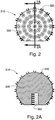
- the dental bur 310 of Figs. 2 and 2A further includes outwardly punched projections 320 which serve as cutting elements.
- the outward projections 320 in bur 310, of Figs. 2 and 2A are mechanically designed to either deflect or abrade upon encountering dentin of preselected hardness. Such a design may easily be made by those skilled in the art by reference to the dimensions and the material used in the construction of the upstanding projections, constituting cutting elements 320 in the bur of Figs. 2 and 2A .
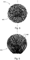
- the embodiments as shown in Figs. 3 and 5 , comprise dental burs wherein the cutting elements, which may be disposed over a mounting ball as in previous embodiments, comprise relatively hard, wire-like cutting material 420, in Fig. 3 , or material 620, in Fig. 5 .
- the material is sufficiently resistant to deflecting and abrading to cut softer dentin material, but sufficiently deflectable or abradable so as to avoid cutting or damaging healthy dentin material. This may be useful to avoid interruption of the cutting action in other burs in which narrow grooves in a bur 210 of the type shown in Fig. 1 , or a more dense cutting material in a bur 510 of the type shown in Fig.
- the cutting effectiveness of the wires shown in Figs. 3 and 5 will be determined by the design factors of the shape resilience of the wire selected in relation to the cross section of the individual wire filaments, and the density of the bulk wire. This is a relationship of the space occupied by the wire itself versus the space occupied by the interstices surrounding the wire. Material selection will also be an important part of the design consideration in the development of cutting elements based on wire-like materials in accordance with these embodiments.
- the dental bur 510 comprises a ball member with pores 520.
- the residual surrounding material of the pores 520 at the outer surface of the ball like bur 510 comprise cutting elements which, as in previous embodiments, are designed with respect to the material of construction and the dimensions.
- Ball like bur 510 also includes recess 540 for mounting bur 510 on a conventional dental drilling apparatus.
- a porous cutting bur 510 as shown in Figs. 4 and 4A may also be designed specifically to provide sufficient porosity to retain carious dentin removed from the drilling surface so as to avoid interruption of the cutting process.
Landscapes
- Health & Medical Sciences (AREA)
- Oral & Maxillofacial Surgery (AREA)
- Dentistry (AREA)
- Epidemiology (AREA)
- Life Sciences & Earth Sciences (AREA)
- Animal Behavior & Ethology (AREA)
- General Health & Medical Sciences (AREA)
- Public Health (AREA)
- Veterinary Medicine (AREA)
- Dental Tools And Instruments Or Auxiliary Dental Instruments (AREA)
- Dental Preparations (AREA)
- Saccharide Compounds (AREA)
- Instructional Devices (AREA)
Abstract
Description
- This invention relates generally to the field of dental cutting tools, and more specifically to a dental bur that selectively removes carious dentin without removing healthy dentin.
- There are many common dental instruments used for removing carious dentin from teeth. Typically, however, unless the operator senses when a harder material is encountered and immediately ceases drilling, prior art burs will continue to cut into normal dentin during and after removal of the carious dentin. Because of the difficulty in sensing precisely when harder material is encountered, the side effect of using such a bur is some cutting of normal healthy dentin. In addition, this produces an infected and clogged bur that is relatively expensive to discard and difficult to sterilize.
-
DE 298 10 111 U1 relates to a medical or dental instrument with a tool holder to those front end a tool with a tool shaft and a working body arranged on it is connected detachably by a holding device to tool holder, wherein the tool can be moved by a drive to perform its working movement, or tool for such instrument. - It is the object of the present invention to provide a dental bur which can remove carious dentin but terminates its operation upon encountering non-carious dentin.
- This object is achieved by the features of the characterizing part of claim 1 coupling the termination of the removal operation of the bur to the hardness of non-carious dentin. If the cutting elements encounters non-carious dentin as detected by the hardness of the material, the cutting elements deflect, deform or abrade and render the cutting elements temporarily or permanently inoperable.
- The subclaims are directed to suitable embodiments of the subject-matter of claim 1.
- The dental cutting tool (or "bur") of the present invention has a working surface that includes cutting elements adapted to cut or drill selectively only material of less than a preselected hardness. When material above the preselected level of hardness is encountered, the cutting elements deflect, deform, or abrade, thus preventing damage to the harder non-carious dentin.
- The invention is best understood from the following detailed description when read in connection with the accompanying drawings, in which:
-
Fig. 1 is a side view of a dental bur formed according to a first exemplary embodiment of the present invention; -
Fig. 1A is a sectional view, in theplane 1A-1A, of the bur shown inFig. 1 ; -
Figures 2, 2A ,4 and 4A relate to an illustrating example which does not form part of the present invention. -
Fig. 2 is a side view of a bur; -
Fig. 2A is a sectional view, in theplane 2A-2A, of the bur shown inFig. 2 ; -
Fig. 3 is a side view of a bur formed according to exemplary an embodiment which is not part of the present invention; -
Fig. 4 is a side view of a bur ; -
Fig. 4A is a sectional view, in theplane 4A-4A, of the bur shown inFig. 4 ; and -
Fig. 5 is a side view of a bur formed according to an embodiment which is not part of the present invention. - Referring now to the Figures, wherein like reference numerals refer to like steps and elements throughout,
Figs. 1 and 1A are side and sectional views, respectively, of the cutting head of a bur according to the first exemplary embodiment of the present invention. As shown inFigs. 1 and 1A ,bur 210 includesbur blades 220 interposed betweengrooves 230.Bur blades 220 are formed so that they will cut soft carious dentin, but will bend inward into the space ofgrooves 230 upon reaching a dentin of a specified hardness and renderbur 210 temporarily or permanently inoperable. Optimally,blades 220 may includeconcavity 225 to effect better control of the deflection, deformation, and/or abrasion ofblades 220 upon encountering a resistant force above a preselected level, characteristic of the maximum force needed to cut carious dentin, without cutting healthy dentin. This may vary with different individual situations, patients, or patient groups but, generally, the lower level of hardness for normal dentin is in the range of about 20 to about 60 Knoop Hardness Number (KHN). Thus, the blades (or cutting elements in other embodiments) of the present invention would be constructed so as to deflect, deform, or abrade upon encountering material above a preselected hardness, preferably above 60 KHN. - Skilled designers can readily
design blades 220 so as to deflect at the preselected resistant force by proper selection of the material of construction ofblades 220, and the dimensions thereof, particularly the height of each blade and the varying width of each blade. In addition, as indicated above,concavities 225 can be incorporated into the design of theblades 220 to optimize deflection or deformation. - The number of
bur blades 220 can be increased or reduced according to design parameters. Similarly, the depth ofgrooves 230 can be varied and the surface area ofbur blades 220 can be increased or decreased according to specific design parameters. For example, the number ofbur blades 220 can be reduced andgrooves 230 can be deepened to increase the scooping effect in soft dentin, and to decrease the efficiency ofbur blades 220 as the bur approaches harder material. - Still another important design variable, which the skilled designer will optimize for optimum performance is
concavity 225, the slope and depth of which may vary considerably. For example, an angular indentation may also perform this deflection-effecting function (i.e., to control the resistance level at whichbur blade 220 will defect). - Certain embodiments of
bur blades 220 can recover to their initial shape after bending back intogrooves 230 and may be available then to cut more superficial, softer carious dentin. These include silicone rubber and resilient, molded plastic embodiments. The ability to recover allows for removal of carious dentin by multiple vertical approaches. In other alternative embodiments ofbur 210, constructed of aluminum, aluminum alloy, hard ceramic, and plastic,blades 220 will deform or abrade and be rendered inoperable. - The shape of
blades 220 andgrooves 230 may be better seen from the cross sectional view ofbur 210 inFig. 1A . Bur 210 may be manufactured by machining a relatively hard metal sphere, such as one comprised of aluminum or aluminum alloy. Alternatively,blades 220 may be separately formed and secured to an underlying base. In either case,blades 220 may be anchored through a shank to a central pin extending throughblades 220 and the core. - The shank is standard sized, such as described in American National Standards Institute/American Dental Association (ANSI/ADA) Specification No. 23 (dental excavating burs). The shank may be constructed of steel, aluminum, or other suitable materials. Both latch type (Class 1-Angle handpiece) and friction grip (Class 4-Angle handpiece) shanks may be used in the excavator of the present invention. Bur 210 may also be injection molded from liquid silicone rubber for example.
- The color of
bur 210 can be made unique for each size bur and for each hardness level at whichbur 210 is molded. This allows the user ofbur 210 to identify quickly the desired size and hardness level of the bur needed. The head of the bur can be spherical or egg-shaped, having a diameter between about 0.6 mm and about 4.0 mm. In addition, the head can have alternative shapes that are compatible with the cutting elements of the present invention. The head can be made out of a variety of materials, including molded plastic, optionally polymethylmethacrylate, silicone rubber, wire ball, polymer wool, aluminum or aluminum alloy, cast alloy, and ceramic. - As an alternative to the design of
blades 220 which deflect upon encountering a preselected resistance force,bur blades 220 may be composed of an abradable material, such as hard ceramic elements embedded in a resinous base, designed to fracture or release the ceramic element when the preselected resistance force is encountered.Bur 210 may also be machinable from a hard ceramic material or injection molded from plastic material. - Still other characteristics may be designed into
blades 220 by increasing or decreasing the distance betweenconsecutive blades 220 and, thus, enlarging or reducing the area of the grooves whereblades 220 may retract. - In the following, an illustrative example, which does not form part of the present invention, is described with reference to
Figures 2, 2A ,4 and 4A . - Still other alternative bur designs are shown, for example, in
Fig. 2 , a side view ofbur 310 , and inFig. 2A , a cross section ofbur 310 shown inFig. 2 .Fig. 3 showsbur 410 havingwires 420 in a polymer wool ball.Fig. 4 showsbur 510 in a ball like structure andFig. 4A shows a cross section ofbur 510 shown inFig. 4 .Fig. 5 showsbur 610 also havingwires 620 in an alternative ball like structure. - The burs shown in
Figs. 2-5 all vary in their mechanical design but each present cutting elements that either deflect, deform, or abrade upon encountering a preselected cutting resistance force. This force is characteristic of the differential force below which soft or carious dentin may be cut or drilled by the bur and above which the cutting action would also be effective against healthy dentin. - These different mechanical forms of the present invention include, in
Figs. 2 and 2A , a ball likecentral element 300 with a threadedrecess 302 for mounting the bur on a conventional dental drilling apparatus. Although not shown in the Figures, such a mounting recess would necessarily be included in all bur heads made of a different material than the shank, i.e., machined ceramic, molded silicone rubber, wire ball, polymer wool ball, and ceramic foam versions. Moreover, the mounting recess is not necessary when the material for the entire excavator (blades, core, and shank) is the same, i.e., machined aluminum or aluminum alloy and molded plastic versions. As described above, the shank of the excavator would conform to ANSI/ADA specifications. Thedental bur 310 ofFigs. 2 and 2A further includes outwardly punchedprojections 320 which serve as cutting elements. Like the cutting blades ofbur 210 inFig. 1 , theoutward projections 320 inbur 310, ofFigs. 2 and 2A , are mechanically designed to either deflect or abrade upon encountering dentin of preselected hardness. Such a design may easily be made by those skilled in the art by reference to the dimensions and the material used in the construction of the upstanding projections, constituting cuttingelements 320 in the bur ofFigs. 2 and 2A . - In addition, the embodiments, as shown in
Figs. 3 and 5 , comprise dental burs wherein the cutting elements, which may be disposed over a mounting ball as in previous embodiments, comprise relatively hard, wire-like cutting material 420, inFig. 3 , ormaterial 620, inFig. 5 . The material is sufficiently resistant to deflecting and abrading to cut softer dentin material, but sufficiently deflectable or abradable so as to avoid cutting or damaging healthy dentin material. This may be useful to avoid interruption of the cutting action in other burs in which narrow grooves in abur 210 of the type shown inFig. 1 , or a more dense cutting material in abur 510 of the type shown inFig. 4 , become fully loaded with carious dentin removed from the drilling surface, thus impeding a further cutting action. The cutting effectiveness of the wires shown inFigs. 3 and 5 will be determined by the design factors of the shape resilience of the wire selected in relation to the cross section of the individual wire filaments, and the density of the bulk wire. This is a relationship of the space occupied by the wire itself versus the space occupied by the interstices surrounding the wire. Material selection will also be an important part of the design consideration in the development of cutting elements based on wire-like materials in accordance with these embodiments. - Still another embodiment is that shown in
Figs. 4 and 4A , in which thedental bur 510 comprises a ball member with pores 520. The residual surrounding material of thepores 520 at the outer surface of the ball likebur 510 comprise cutting elements which, as in previous embodiments, are designed with respect to the material of construction and the dimensions. Ball likebur 510 also includesrecess 540 for mountingbur 510 on a conventional dental drilling apparatus. Aporous cutting bur 510 as shown inFigs. 4 and 4A may also be designed specifically to provide sufficient porosity to retain carious dentin removed from the drilling surface so as to avoid interruption of the cutting process. - Although illustrated and described herein with reference to certain specific embodiments, the present invention is nevertheless not intended to be limited to the details shown. Rather, various modifications may be made in the details within the scope of the claims.
Claims (13)
- A dental bur (210; 310; 410; 510; 610) for use in removing carious dentin from teeth, said bur (210; 310; 410; 510; 610) comprising a working surface, a rotatable shank and a central pin, wherein the working surface includes cutting elements (220; 320) anchored through said rotatable shank to said central pin, wherein said cutting elements (220; 320; 420; 620) are rotatable about a longitudinal axis of said rotatable shank wherein said cutting elements (220; 320) are interposed between adjacent grooves (230), characterized in that said cutting elements (220; 320) are formed of a material adapted to deflect or deform inward into a space of said grooves (230) or abrade upon reaching a dentin above a preselected hardness and render the bur (210; 310) inoperable, wherein the cutting elements are either blades or external projections.
- The dental bur according to claim 1, characterized in that said bur (210; 310; 410; 510; 610) is positioned on a mounting member adapted to be retained in and activated by a dental drilling apparatus.
- The dental bur according to claim 2, characterized in that said mounting member is removably positioned on said dental drilling apparatus.
- The dental bur according to claim 3, characterized in that said cutting elements are the external projections (320) disposed over a ball like structure surface (300).
- The dental bur according to claim 4, characterized in that said cutting elements (320) are comprised of a metal.
- The dental bur as recited in claim 5, characterized in that said metal is aluminium or an aluminium alloy.
- The dental bur according to claim 1, wherein the blades are a plurality of outwardly projecting blades (220) interposed between a plurality of grooves in a ball like structure.
- The dental bur according to claim 7, characterized in that said cutting elements (220) are comprised of aluminium or aluminium alloy.
- The dental bur according to claim 1, characterized in that said abradable cutting elements comprise a hard ceramic or plastic material, said abradable cutting elements are embedded in a material that is substantially softer than ceramic or plastic material.
- The dental bur according to claim 1, characterized in that said cutting elements are adapted to deflect, deform, or abrade upon encountering material having a hardness at or above about 20 Knoop Hardness Number.
- The dental bur according to claim 1, characterized in that the cutting elements (220) comprise a plurality of blades (220) extending radially outwardly from the bur.
- The dental bur according to claim 11 comprising six blades (220).
- The dental bur according to claim 1, wherein the preselected hardness is above 60 Knoop Hardness Number.
Applications Claiming Priority (3)
| Application Number | Priority Date | Filing Date | Title |
|---|---|---|---|
| US09/211,402 US6106291A (en) | 1998-12-15 | 1998-12-15 | Selective dentin caries excavator |
| US211402 | 1998-12-15 | ||
| PCT/US1999/028162 WO2000035368A1 (en) | 1998-12-15 | 1999-11-29 | Selective dentin caries excavator |
Publications (3)
| Publication Number | Publication Date |
|---|---|
| EP1143873A1 EP1143873A1 (en) | 2001-10-17 |
| EP1143873A4 EP1143873A4 (en) | 2005-06-08 |
| EP1143873B1 true EP1143873B1 (en) | 2012-05-02 |
Family
ID=22786780
Family Applications (1)
| Application Number | Title | Priority Date | Filing Date |
|---|---|---|---|
| EP99960601A Expired - Lifetime EP1143873B1 (en) | 1998-12-15 | 1999-11-29 | Selective dentin caries excavator |
Country Status (9)
| Country | Link |
|---|---|
| US (1) | US6106291A (en) |
| EP (1) | EP1143873B1 (en) |
| JP (2) | JP4590103B2 (en) |
| AT (1) | ATE555740T1 (en) |
| AU (1) | AU1746200A (en) |
| BR (1) | BR9916234B1 (en) |
| CA (1) | CA2351399C (en) |
| ES (1) | ES2387247T3 (en) |
| WO (1) | WO2000035368A1 (en) |
Families Citing this family (17)
| Publication number | Priority date | Publication date | Assignee | Title |
|---|---|---|---|---|
| US6106291A (en) * | 1998-12-15 | 2000-08-22 | Temple University Of The Commonwealth System Of Higher Education | Selective dentin caries excavator |
| US6579092B1 (en) * | 1999-08-09 | 2003-06-17 | Lightspeed Technology, Inc. | Endodontic instruments with means for breakage containment |
| US6347941B1 (en) * | 2001-02-23 | 2002-02-19 | Temple University Of The Commonwealth System Of Higher Education | Partial dentin caries excavator |
| US7008223B2 (en) * | 2003-11-19 | 2006-03-07 | Essential Dental Systems, Inc. | Endodontic instrument for accessing a pulp chamber |
| EP1844727A1 (en) * | 2006-04-12 | 2007-10-17 | 3M Innovative Properties Company | Dental instrument for removing solely unremineralisable carious dentin |
| DE102006018933B4 (en) * | 2006-04-24 | 2008-01-24 | Gebr. Brasseler Gmbh & Co. Kg | Dental drills |
| US20080038691A1 (en) * | 2006-08-10 | 2008-02-14 | Walling Donny T | Denture Adjustment Tool |
| WO2009017148A1 (en) | 2007-08-01 | 2009-02-05 | Mani, Inc. | Stainless steel bar |
| JP5205646B2 (en) * | 2007-08-01 | 2013-06-05 | マニー株式会社 | Stainless steel bar |
| JP5205647B2 (en) * | 2007-08-30 | 2013-06-05 | マニー株式会社 | Stainless steel bar |
| JP5326163B2 (en) * | 2007-08-01 | 2013-10-30 | マニー株式会社 | Stainless steel bar |
| DE102008010049B3 (en) * | 2008-02-20 | 2009-01-02 | Gebr. Brasseler Gmbh & Co. Kg | Dental drill, has head provided with cutting edges, where two of cutting edges cross over at front side in intersection cutting edge and drill is made of plastic material exhibiting specific hardness |
| DE102011010897B4 (en) | 2011-02-10 | 2023-02-09 | Gebr. Brasseler Gmbh & Co. Kg | Dental instrument and method for its manufacture |
| US20140106297A1 (en) * | 2012-10-11 | 2014-04-17 | University Of Zurich | Dental bur and method for removing a soft deposit |
| GB2509739A (en) * | 2013-01-11 | 2014-07-16 | Nobel Biocare Services Ag | Dental drill bit with spherical head and helical fluting |
| DE102014203453B4 (en) * | 2014-02-26 | 2024-05-16 | Gebr. Brasseler Gmbh & Co. Kg | Dental instrument |
| PL238482B1 (en) * | 2018-01-30 | 2021-08-30 | Habryn Andrzej | Surgical, preferably dentist's tool, with required durability of its working part |
Family Cites Families (26)
| Publication number | Priority date | Publication date | Assignee | Title |
|---|---|---|---|---|
| US503744A (en) * | 1893-08-22 | Woodbury storer how | ||
| US463619A (en) * | 1891-11-24 | Pneumatic ink-eraser | ||
| US706013A (en) * | 1901-07-29 | 1902-08-05 | Thomas J Boyce | Rotary scraper for finishing artificial dentures. |
| US1225230A (en) * | 1916-09-28 | 1917-05-08 | George N Elwin | Rotary tooth-brush. |
| US1636577A (en) * | 1926-06-28 | 1927-07-19 | Carl G Schuller | Rotary cutting tool |
| DE2303148A1 (en) * | 1972-02-14 | 1974-07-25 | Daiberl Karl | DRILLING, MILLING OR GRINDING TOOL FOR DENTAL PURPOSES |
| US4190958A (en) * | 1978-01-17 | 1980-03-04 | Howard Martin | Endodontic drill-file |
| US4283175A (en) * | 1979-11-05 | 1981-08-11 | Syntex (U.S.A.) Inc. | Dental scaler having scaling tip with rounded edge work surfaces particularly suitable for circular or ellipsoidal patterns of vibration |
| US4365958A (en) * | 1981-06-17 | 1982-12-28 | Vlock D G | Combined dental drill and anchor pin |
| SE430389B (en) * | 1981-09-10 | 1983-11-14 | Dentatus Ab | TOOLS FOR NOTICE PROCESSING |
| US4449937A (en) * | 1981-12-03 | 1984-05-22 | Ipco Corporation | Dental anchor |
| JPH0228877Y2 (en) * | 1985-04-02 | 1990-08-02 | ||
| US4661061A (en) * | 1985-07-22 | 1987-04-28 | Howard Martin | Four sided root canal rasp for root canal preparation |
| US4684346A (en) * | 1985-07-22 | 1987-08-04 | Howard Martin | Endodontic access bur with extended diamond coat and method for using |
| WO1990005498A1 (en) * | 1988-11-18 | 1990-05-31 | Bernard Weissman | Dental reamer tool |
| CH679008A5 (en) * | 1989-03-21 | 1991-12-13 | Maillefer Auguste Sa | |
| JPH0773588B2 (en) * | 1992-07-09 | 1995-08-09 | 株式会社マシンツール中央 | Dental grinding / polishing material |
| US5299937A (en) * | 1992-07-29 | 1994-04-05 | Si Diamond Technology, Inc. | Dental instruments having diamond-like working surface |
| US5316475A (en) * | 1993-02-05 | 1994-05-31 | Rosenberg Neil A | Dental prophy cup |
| JP2670420B2 (en) * | 1993-11-18 | 1997-10-29 | 株式会社吉田製作所 | Laser cutting equipment |
| US5676593A (en) * | 1995-08-08 | 1997-10-14 | Stevens; Richard B. | Cutter for soft materials and method for making it |
| US5601430A (en) * | 1995-09-15 | 1997-02-11 | Kreativ, Inc. | Process for the removal of soft tooth decay using a unique abrasive fluid stream |
| US5882201A (en) * | 1997-01-21 | 1999-03-16 | Salem; George | Dental debridement method and tool therefor |
| US5779476A (en) * | 1997-04-30 | 1998-07-14 | Roetzer; Patrick | Rapid adapting precision transformer for occlusal resins |
| DE29810111U1 (en) * | 1997-08-20 | 1998-11-05 | Kaltenbach & Voigt Gmbh & Co, 88400 Biberach | Medical or dental instrument and tool for such an instrument |
| US6106291A (en) * | 1998-12-15 | 2000-08-22 | Temple University Of The Commonwealth System Of Higher Education | Selective dentin caries excavator |
-
1998
- 1998-12-15 US US09/211,402 patent/US6106291A/en not_active Expired - Lifetime
-
1999
- 1999-11-29 EP EP99960601A patent/EP1143873B1/en not_active Expired - Lifetime
- 1999-11-29 WO PCT/US1999/028162 patent/WO2000035368A1/en not_active Ceased
- 1999-11-29 CA CA002351399A patent/CA2351399C/en not_active Expired - Fee Related
- 1999-11-29 ES ES99960601T patent/ES2387247T3/en not_active Expired - Lifetime
- 1999-11-29 JP JP2000587690A patent/JP4590103B2/en not_active Expired - Fee Related
- 1999-11-29 AT AT99960601T patent/ATE555740T1/en active
- 1999-11-29 BR BRPI9916234-2A patent/BR9916234B1/en not_active IP Right Cessation
- 1999-11-29 AU AU17462/00A patent/AU1746200A/en not_active Abandoned
-
2008
- 2008-07-23 JP JP2008190318A patent/JP4794608B2/en not_active Expired - Fee Related
Also Published As
| Publication number | Publication date |
|---|---|
| WO2000035368A1 (en) | 2000-06-22 |
| ES2387247T3 (en) | 2012-09-18 |
| JP2008272513A (en) | 2008-11-13 |
| AU1746200A (en) | 2000-07-03 |
| JP4590103B2 (en) | 2010-12-01 |
| JP2002532133A (en) | 2002-10-02 |
| ATE555740T1 (en) | 2012-05-15 |
| EP1143873A1 (en) | 2001-10-17 |
| EP1143873A4 (en) | 2005-06-08 |
| US6106291A (en) | 2000-08-22 |
| CA2351399C (en) | 2010-03-09 |
| BR9916234B1 (en) | 2008-11-18 |
| BR9916234A (en) | 2001-09-04 |
| CA2351399A1 (en) | 2000-06-22 |
| JP4794608B2 (en) | 2011-10-19 |
Similar Documents
| Publication | Publication Date | Title |
|---|---|---|
| JP4794608B2 (en) | Excavator to select carious dentin | |
| CA2438918C (en) | Partial dentin caries excavator | |
| US6976844B2 (en) | Ultrasonic microtube dental instruments and methods of using same | |
| US20070248935A1 (en) | Dental drill | |
| JP6203642B2 (en) | Endodontic drill, kit and method for using an endodontic drill | |
| EP2114287A1 (en) | Endodontic file | |
| KR20110117692A (en) | Interlocking devices that can be connected to piles and vibrating handpieces for acting on tooth gaps in orthodontics as well as conservative treatment and prevention of teeth | |
| CA2500644C (en) | Improved dental bur | |
| WO1990005498A1 (en) | Dental reamer tool | |
| US5100322A (en) | Water-cooled friction contour cutting dental tool | |
| US6676410B2 (en) | Grinding bar | |
| MXPA01006066A (en) | Selective dentin caries excavator | |
| WO2001052764A1 (en) | Retention quill for a chucking system in a dental handpiece | |
| US20050244785A1 (en) | Rotary dental file having a safe breakage point | |
| JP3818738B2 (en) | Embedded material cutting bit | |
| KR102840164B1 (en) | Dental drill | |
| JPS6213014B2 (en) | ||
| JP5205646B2 (en) | Stainless steel bar | |
| JP2006503664A (en) | Self-controlled occlusal cutting bar and method of use | |
| WO2003047452A1 (en) | Bent structure for dental instruments | |
| WO2003075780A1 (en) | Bending structure of dental instruments |
Legal Events
| Date | Code | Title | Description |
|---|---|---|---|
| PUAI | Public reference made under article 153(3) epc to a published international application that has entered the european phase |
Free format text: ORIGINAL CODE: 0009012 |
|
| 17P | Request for examination filed |
Effective date: 20010521 |
|
| AK | Designated contracting states |
Kind code of ref document: A1 Designated state(s): AT BE CH CY DE DK ES FI FR GB GR IE IT LI LU MC NL PT SE |
|
| AX | Request for extension of the european patent |
Free format text: AL;LT;LV;MK;RO;SI |
|
| A4 | Supplementary search report drawn up and despatched |
Effective date: 20050426 |
|
| 17Q | First examination report despatched |
Effective date: 20051215 |
|
| 17Q | First examination report despatched |
Effective date: 20051215 |
|
| GRAP | Despatch of communication of intention to grant a patent |
Free format text: ORIGINAL CODE: EPIDOSNIGR1 |
|
| GRAS | Grant fee paid |
Free format text: ORIGINAL CODE: EPIDOSNIGR3 |
|
| GRAA | (expected) grant |
Free format text: ORIGINAL CODE: 0009210 |
|
| AK | Designated contracting states |
Kind code of ref document: B1 Designated state(s): AT BE CH CY DE DK ES FI FR GB GR IE IT LI LU MC NL PT SE |
|
| REG | Reference to a national code |
Ref country code: GB Ref legal event code: FG4D |
|
| REG | Reference to a national code |
Ref country code: AT Ref legal event code: REF Ref document number: 555740 Country of ref document: AT Kind code of ref document: T Effective date: 20120515 Ref country code: CH Ref legal event code: EP |
|
| REG | Reference to a national code |
Ref country code: IE Ref legal event code: FG4D |
|
| REG | Reference to a national code |
Ref country code: SE Ref legal event code: TRGR |
|
| REG | Reference to a national code |
Ref country code: DE Ref legal event code: R096 Ref document number: 69944188 Country of ref document: DE Effective date: 20120705 |
|
| REG | Reference to a national code |
Ref country code: CH Ref legal event code: NV Representative=s name: E. BLUM & CO. AG PATENT- UND MARKENANWAELTE VSP |
|
| REG | Reference to a national code |
Ref country code: NL Ref legal event code: VDEP Effective date: 20120502 |
|
| REG | Reference to a national code |
Ref country code: ES Ref legal event code: FG2A Ref document number: 2387247 Country of ref document: ES Kind code of ref document: T3 Effective date: 20120918 |
|
| PG25 | Lapsed in a contracting state [announced via postgrant information from national office to epo] |
Ref country code: CY Free format text: LAPSE BECAUSE OF FAILURE TO SUBMIT A TRANSLATION OF THE DESCRIPTION OR TO PAY THE FEE WITHIN THE PRESCRIBED TIME-LIMIT Effective date: 20120502 Ref country code: FI Free format text: LAPSE BECAUSE OF FAILURE TO SUBMIT A TRANSLATION OF THE DESCRIPTION OR TO PAY THE FEE WITHIN THE PRESCRIBED TIME-LIMIT Effective date: 20120502 |
|
| REG | Reference to a national code |
Ref country code: AT Ref legal event code: MK05 Ref document number: 555740 Country of ref document: AT Kind code of ref document: T Effective date: 20120502 |
|
| PG25 | Lapsed in a contracting state [announced via postgrant information from national office to epo] |
Ref country code: PT Free format text: LAPSE BECAUSE OF FAILURE TO SUBMIT A TRANSLATION OF THE DESCRIPTION OR TO PAY THE FEE WITHIN THE PRESCRIBED TIME-LIMIT Effective date: 20120903 Ref country code: GR Free format text: LAPSE BECAUSE OF FAILURE TO SUBMIT A TRANSLATION OF THE DESCRIPTION OR TO PAY THE FEE WITHIN THE PRESCRIBED TIME-LIMIT Effective date: 20120803 |
|
| PG25 | Lapsed in a contracting state [announced via postgrant information from national office to epo] |
Ref country code: BE Free format text: LAPSE BECAUSE OF FAILURE TO SUBMIT A TRANSLATION OF THE DESCRIPTION OR TO PAY THE FEE WITHIN THE PRESCRIBED TIME-LIMIT Effective date: 20120502 |
|
| PG25 | Lapsed in a contracting state [announced via postgrant information from national office to epo] |
Ref country code: DK Free format text: LAPSE BECAUSE OF FAILURE TO SUBMIT A TRANSLATION OF THE DESCRIPTION OR TO PAY THE FEE WITHIN THE PRESCRIBED TIME-LIMIT Effective date: 20120502 Ref country code: NL Free format text: LAPSE BECAUSE OF FAILURE TO SUBMIT A TRANSLATION OF THE DESCRIPTION OR TO PAY THE FEE WITHIN THE PRESCRIBED TIME-LIMIT Effective date: 20120502 Ref country code: AT Free format text: LAPSE BECAUSE OF FAILURE TO SUBMIT A TRANSLATION OF THE DESCRIPTION OR TO PAY THE FEE WITHIN THE PRESCRIBED TIME-LIMIT Effective date: 20120502 |
|
| PLBE | No opposition filed within time limit |
Free format text: ORIGINAL CODE: 0009261 |
|
| STAA | Information on the status of an ep patent application or granted ep patent |
Free format text: STATUS: NO OPPOSITION FILED WITHIN TIME LIMIT |
|
| 26N | No opposition filed |
Effective date: 20130205 |
|
| REG | Reference to a national code |
Ref country code: DE Ref legal event code: R097 Ref document number: 69944188 Country of ref document: DE Effective date: 20130205 |
|
| REG | Reference to a national code |
Ref country code: IE Ref legal event code: MM4A |
|
| PG25 | Lapsed in a contracting state [announced via postgrant information from national office to epo] |
Ref country code: IE Free format text: LAPSE BECAUSE OF NON-PAYMENT OF DUE FEES Effective date: 20121129 |
|
| PG25 | Lapsed in a contracting state [announced via postgrant information from national office to epo] |
Ref country code: MC Free format text: LAPSE BECAUSE OF NON-PAYMENT OF DUE FEES Effective date: 20121130 |
|
| PG25 | Lapsed in a contracting state [announced via postgrant information from national office to epo] |
Ref country code: LU Free format text: LAPSE BECAUSE OF NON-PAYMENT OF DUE FEES Effective date: 20121129 |
|
| PGFP | Annual fee paid to national office [announced via postgrant information from national office to epo] |
Ref country code: GB Payment date: 20141027 Year of fee payment: 16 Ref country code: ES Payment date: 20141105 Year of fee payment: 16 Ref country code: SE Payment date: 20141107 Year of fee payment: 16 Ref country code: CH Payment date: 20141027 Year of fee payment: 16 Ref country code: FR Payment date: 20141027 Year of fee payment: 16 |
|
| REG | Reference to a national code |
Ref country code: CH Ref legal event code: PL |
|
| GBPC | Gb: european patent ceased through non-payment of renewal fee |
Effective date: 20151129 |
|
| PG25 | Lapsed in a contracting state [announced via postgrant information from national office to epo] |
Ref country code: CH Free format text: LAPSE BECAUSE OF NON-PAYMENT OF DUE FEES Effective date: 20151130 Ref country code: LI Free format text: LAPSE BECAUSE OF NON-PAYMENT OF DUE FEES Effective date: 20151130 |
|
| REG | Reference to a national code |
Ref country code: FR Ref legal event code: ST Effective date: 20160729 |
|
| PG25 | Lapsed in a contracting state [announced via postgrant information from national office to epo] |
Ref country code: SE Free format text: LAPSE BECAUSE OF NON-PAYMENT OF DUE FEES Effective date: 20151130 |
|
| PG25 | Lapsed in a contracting state [announced via postgrant information from national office to epo] |
Ref country code: GB Free format text: LAPSE BECAUSE OF NON-PAYMENT OF DUE FEES Effective date: 20151129 |
|
| PG25 | Lapsed in a contracting state [announced via postgrant information from national office to epo] |
Ref country code: FR Free format text: LAPSE BECAUSE OF NON-PAYMENT OF DUE FEES Effective date: 20151130 |
|
| REG | Reference to a national code |
Ref country code: ES Ref legal event code: FD2A Effective date: 20170131 |
|
| PG25 | Lapsed in a contracting state [announced via postgrant information from national office to epo] |
Ref country code: ES Free format text: LAPSE BECAUSE OF NON-PAYMENT OF DUE FEES Effective date: 20151130 |
|
| PGFP | Annual fee paid to national office [announced via postgrant information from national office to epo] |
Ref country code: DE Payment date: 20171130 Year of fee payment: 19 |
|
| PGFP | Annual fee paid to national office [announced via postgrant information from national office to epo] |
Ref country code: IT Payment date: 20171113 Year of fee payment: 19 |
|
| REG | Reference to a national code |
Ref country code: DE Ref legal event code: R119 Ref document number: 69944188 Country of ref document: DE |
|
| PG25 | Lapsed in a contracting state [announced via postgrant information from national office to epo] |
Ref country code: IT Free format text: LAPSE BECAUSE OF NON-PAYMENT OF DUE FEES Effective date: 20181129 Ref country code: DE Free format text: LAPSE BECAUSE OF NON-PAYMENT OF DUE FEES Effective date: 20190601 |