EP1143712A2 - Method and apparatus for calculating motion vectors - Google Patents
Method and apparatus for calculating motion vectors Download PDFInfo
- Publication number
- EP1143712A2 EP1143712A2 EP01103501A EP01103501A EP1143712A2 EP 1143712 A2 EP1143712 A2 EP 1143712A2 EP 01103501 A EP01103501 A EP 01103501A EP 01103501 A EP01103501 A EP 01103501A EP 1143712 A2 EP1143712 A2 EP 1143712A2
- Authority
- EP
- European Patent Office
- Prior art keywords
- block
- image
- pixels
- pixel
- blocks
- Prior art date
- Legal status (The legal status is an assumption and is not a legal conclusion. Google has not performed a legal analysis and makes no representation as to the accuracy of the status listed.)
- Withdrawn
Links
Images


Classifications
-
- H—ELECTRICITY
- H04—ELECTRIC COMMUNICATION TECHNIQUE
- H04N—PICTORIAL COMMUNICATION, e.g. TELEVISION
- H04N5/00—Details of television systems
- H04N5/14—Picture signal circuitry for video frequency region
- H04N5/144—Movement detection
- H04N5/145—Movement estimation
-
- H—ELECTRICITY
- H04—ELECTRIC COMMUNICATION TECHNIQUE
- H04N—PICTORIAL COMMUNICATION, e.g. TELEVISION
- H04N7/00—Television systems
- H04N7/01—Conversion of standards, e.g. involving analogue television standards or digital television standards processed at pixel level
- H04N7/0117—Conversion of standards, e.g. involving analogue television standards or digital television standards processed at pixel level involving conversion of the spatial resolution of the incoming video signal
- H04N7/012—Conversion between an interlaced and a progressive signal
Definitions
- the present invention relates to a method and apparatus for calculating motion vectors and, in particular, to a motion vector calculation suitable for use in a video de-interlacing system.
- Digital television (DTV) signals conforming, for example, to the Advanced Television Systems Committee (ATSC) standard may have a large number of formats. These formats are typically referenced by the number of horizontal lines in the image and whether each image frame is formed from two fields, each containing alternate lines of the frame (interlaced) or from a single image field containing all of the lines of the frame (progressive). Listed from highest resolution to lowest resolution, the television signal formats defined by the ATSC standard are referenced by the designations, 10801, 720P, 480P and 480I. In these designations, the number refers to the number of horizontal lines in the image and the letter defines the resulting image as being interlaced (I) or progressive (P).
- ATSC Advanced Television Systems Committee
- NTSC National Television Standards Committee
- ATSC television receivers may support many different types of monitors.
- An ATSC receiver may, for example, be connected to a multi-sync monitor that can adapt to display whatever signal type is being received.
- This type of multi-sync monitor is typically referred to as a native mode monitor as it allows each possible type of ATSC signal to be displayed at its intended resolution.
- ATSC receivers may be purchased that can be connected to a standard NTSC monitor.
- One such receiver is the TU-DST51 DTV Decoder Set-Top Box manufactured by Panasonic. This receiver converts each ATSC signal type into a 4801 output signal that may be displayed on the NTSC monitor.
- the Panasonic receiver also supports the other types of monitors, automatically converting the received input signal to the format that is supported by the specified monitor.
- interlaced video signals have artifacts caused by the interlacing of video fields that occur at two different instants.
- One such artifact is vertical dot crawl. This artifact occurs at vertical edges in the image, typically at edges between portions of the image having different colors. As the name implies, the vertical dot crawl artifact is seen as a line of dots that seem to move from the bottom to the top of the frame. If the display device supports progressive video signals, these artifacts of interlaced scanning may be removed, or at least mitigated, by converting the interlaced video signal to a progressive video signal before it is displayed.
- motion compensation systems that use relatively large block sizes typically have good noise performance, that is to say they do not tend to track noise in the image instead of the underlying image content. These systems, however, do not tend to track small objects well. Thus, if a small object moves in the image sequence from one image to the next, a de-interlacing system that uses a large block size may have difficulty matching the moved object to the same object in the current frame. If, on the other hand, the block size is reduced as in the above referenced article, the small object recognition is improved but the noise performance suffers.
- the present invention is embodied in a motion estimation system for finding motion vectors between first and second images.
- the motion estimation system selects first and second overlapping blocks of pixels from the first image.
- the motion estimation system estimates motion between the first and second images to define respective motion vectors for the overlapping blocks. These motion vectors are assigned to respective first and second non-overlapping sub-blocks of pixels within the respective first and second overlapping blocks of pixels.
- Figure 1A is a block diagram of a motion adaptive interlaced scan to progressive scan conversion system in accordance with the present invention.
- Figure 1B is a block diagram of an interlaced to progressive converter suitable for use in the conversion system shown in Figure 1A.
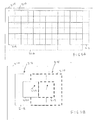
- Figure 2A is an image diagram that is useful for describing the block selection scheme used for motion vector calculation by the motion estimation processor shown in Figure 1A.
- Figure 2B is an image diagram showing a portion of the image diagram shown in Figure 2A.
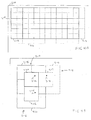
- Figure 3A is an image diagram which is useful for describing the motion vector calculation procedure used by the motion estimation processor shown in Figure 1A.
- Figure 3B is an image diagram that shows a portion of the image diagram of Figure 3A.
- Figure 4A is an image diagram which is useful for describing the motion vector calculation process used by the motion estimation processor of Figure 1A.
- Figure 4B is an image diagram showing a portion of the image diagram of Figure 4A.
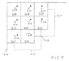
- Figure 5 is an image diagram which illustrates an exemplary process for calculating motion vectors of blocks around the edge of any of the images shown in Figure 2A through 4B.
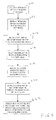
- Figure 6 is a flow-chart diagram that is useful for describing the process of the subject invention.
- FIG. 1 is a block diagram of an exemplary interlaced to progressive scan conversion system according to the present invention.
- an interlaced video signal is received into a current field memory 110.
- the prior contents of the memory 110 are transferred into a prior field memory 112.
- a motion estimation processor 114 is coupled to receive video information from both the current field memory 110 and the prior field memory 112.
- the motion estimation processor 114 as described below, generates motion vectors for the current field based on eight-by-eight blocks of pixels.
- the motion vectors are applied to four-by-four blocks of pixels.
- These motion vectors are used by the interlaced to progressive converter 116 to generate vertically interpolated samples between each pair of samples of the interlaced video signal.
- the current field memory 110, prior field memory 112, motion estimation processor 114, and interlaced to progressive converter 116 are controlled by a controller 118.
- the interlaced to progressive converter 116 is shown in Figure 1B.
- This converter includes an intra-field interpolator 124 and an inter-field interpolator 126.
- the intra-field interpolator 124 vertically averages corresponding samples from adjacent lines in the current interlaced field to generate interstitial samples between the lines.
- the inter-field interpolator 126 filters lines of samples from the current field and from the prior field, as indicated by the motion vector, to produce interpolated samples that are compensated for motion in the image.
- the motion vector generated by the motion estimation circuitry 114 truly reflects motion between the current field and the prior field
- the interpolated lines generated by the interpolator 126 are preferred as the resultant image has greater vertical resolution than if the lines from the intra-field interpolator 124 are used.
- the interpolated samples generated by the inter-field interpolator 126 may include motion distortion that degrades the quality of the image. In this instance, it may be desirable to use the interpolated lines generated by the intra-field interpolator 124.
- motion estimation processor 114 applies a difference value to a comparator 120.
- This value is a measure of the difference between the block in the current field and the corresponding block in the prior field.
- the comparator 120 compares the difference measure to a threshold value provided by a source of digital value (e.g. a register) 122.
- the output signal of comparator 120 is supplied to the control input terminal of a multiplexer 128 which is coupled to receive the intra-field interpolated samples provided by interpolator 124 at one signal input port and the corresponding samples provided by the inter-field interpolator 126 at a second signal input port.
- the comparator causes the multiplexer 128 to provide intra-field interpolated samples as the interpolated output signal 132. If, on the other hand, the difference value provided by the processor 114 is less than threshold value 122, the comparator causes the multiplexer 128 to provide inter-field interpolated samples generated by interpolator 126 as the interpolated output signal 132.
- the interlaced signal of the current field is provided as the interlaced samples 130. Together, the samples provided by the signal lines 130 and 132 form the progressive video image.
- Figure 2A is an image diagram that illustrates the overlapping large blocks used by the motion estimation processor 114 to calculate motion vectors.
- Figure 2A shows an image 210 and three sets of overlapping large blocks defined for the image. These sets of blocks are represented, respectively, by solid lines, dashed lines, and dotted lines.
- the first set of blocks 212 are defined by the solid lines. These blocks are offset from the edge of image 210 by, for example, two pixels in both the horizontal and vertical directions.
- Each exemplary block 218, as outlined by the lines having alternating dashes and dots, includes eight pixels on a side for a total of 64 pixels per large block.
- the second set of blocks 214 represented by the dashed lines, is also composed of eight-by-eight blocks of pixels.
- the third set of eight-by-eight blocks of pixels is the set 216 which is offset from the left side edge of the image 210 by two pixels and from the top edge of the image by six pixels.
- Figure 2B shows a detailed portion of the image shown in Figure 2A including the eight-by-eight block of pixels 218.
- the block of pixels 218 is offset from the left side edge of the image 210 by a two pixel interval 228. This block is also offset from the top side of the image by a two-pixel interval 224.
- the exemplary embodiment of the invention uses conventional motion estimation techniques to define a motion vector 212 based on the eight-by-eight block of pixels 218.
- This motion vector is applied only to a central four-by-four sub-block of pixels 220. As shown in Figure 2B, this central block is offset from the top edge of the block 218 by a two pixel interval 226 and from the left side edge of the block 218 by a two pixel interval 230.
- Figure 2B represents a first step in the motion estimation process performed by the processor 114 shown in Figure 1A.
- the motion estimation processor first defines the block 218 and then calculates a motion vector for the block by comparing the block 218 to corresponding eight-by-eight blocks of pixels from the prior field 112 that are displaced in position over a range of pixel positions (e.g. by plus or minus one to six pixel positions in each of the horizontal and vertical directions).
- the motion vector corresponds to the displacement of the block of the prior image that is within the search range and that best satisfies a matching criterion with respect to the block 218 in the current image 210.
- Exemplary matching algorithms may calculate, for example, the mean absolute difference between the 64 corresponding pairs of pixels in the block.
- FIGS 3A and 3B illustrate a second step in the motion estimation process performed by the processor 114.
- a second eight-by-eight block of pixels, 310 is used to generate a motion vector.
- This block of pixels is from the group of horizontally displaced blocks of pixels 214.
- the block of pixels 310 overlaps the block of pixel 218 by four pixels in the horizontal direction.
- the motion estimation processor 114 generates a motion vector 314 for the entire eight-by-eight block of pixels 310 but applies this motion vector only to the central four by four pixel sub-block 312.
- This block is displaced by two pixels positions in each direction from the edges of the block of pixels 310.
- the small block 312 is immediately adjacent to the small block of pixels 220.
- Figure 4A and 4B illustrate steps that are performed by the motion estimation processor 114 after the last block along the width of the image 210 has been processed using the steps illustrated by Figures 2 and 3.
- the motion estimation process 114 takes a block of samples 410 that is displaced by four-pixel positions in the vertical direction from the top edge of the block of samples 218 and, thus, overlaps the lower four lines of samples in the block.
- the motion estimation processor 114 calculates a motion vector 414 for the entire eight-by-eight block of pixels 410, but applies this motion vector only to the four-by-four central sub-block 412 of the eight-by-eight block of pixels 410.
- the four by four sub-block of pixels 412 is immediately below the four by four sub-block 220.
- the motion estimation process continues using a eight by eight block of pixels (not shown) that is displaced by four pixel positions in both the horizontal and vertical directions from the edges of the blocks of pixels 218.
- This block of pixels thus, overlaps the lower one-quarter of the block 218 and is used to generate a motion vector for a four-by-four block of pixels that is immediately below the four-by-four sub-block 312 and immediately to the right of the four-by-four sub-block of pixels 412. This process continues across the width of the image 210.
- the motion estimation process continues by using the next lower block of pixels from the group of pixels 212 outlined by solid lines in Figures 2A, 3A, and 4A.
- the result of the process illustrated by Figure 2A through 4B is a set of four-by-four blocks of pixels each of which has an associated motion vector.
- the motion vector is computed from a larger eight-by-eight block of pixels and so exhibits superior noise performance.
- the motion estimation processor 114 applies the four-by-four blocks of pixels to the interlaced to progressive converter 114, It also provides a measure of difference between the four by four block of pixels from the current field and the matching four-by-four block of pixels from the prior field.
- This measure of difference may for example, be a mean absolute difference (MAD) of pixel values or a means squared error (MSE) of the pixel values at corresponding positions in the two blocks.
- MAD mean absolute difference
- MSE means squared error
- the motion estimator 114 tracks motion in the image based on eight-by-eight blocks of pixel values, it tends to track image content and not noise. Thus, the estimator 114 exhibits superior noise performance compared to a converter that uses a smaller block size. In addition, because the measure of difference between the matching blocks that is applied to the interlaced to progressive converter 116 is based on the small, four-by-four pixel sub-blocks, the converter 116 is better able to reject false matches of small objects in the image than if a larger block size were used. Thus the interlaced to progressive converter 116 exhibits both good noise performance and good small object tracking.
- motion vectors exist for all of the blocks of pixels in the image except for a line of four pixel by four pixel sub-blocks, that surround the image.
- Motion vectors for these sub-blocks of may be calculated in many ways.
- Figure 5 the four-by-four sub-block of pixels 510 does not have a motion vector defined by the process described above.
- the motion vector 414 calculated for sub-block 412 is copied as the motion -vector 512 for the four-by-four sub-block 510.
- the motion vector 222 of sub-block 220 is copied as the motion vector 516 of sub-block 514; the motion vector 222 is also copied as the motion vector 520 of sub-block 518 and the motion vector 314 of sub-block 312 is copied as the motion vector 524 of sub-block 522.
- Block 526 does not have a calculated motion vector immediately adjacent along one of its edges. In this exemplary embodiment of the invention, however, the motion vector 222 is copied as the motion vector 528 for sub-block 526.
- the sub-blocks 510, 514, 518, 522, and 526 lie along the edge of the image 210, they are less important than blocks more centrally located in the image. This is because the viewers attention is typically directed to the center of the image and not to the edges of the image. Accordingly, the calculation of the motion vectors for these blocks is less important than for blocks near the central portion of the image. In an alternative embodiment of the invention, the motion vectors for these blocks may be set to zero. Alternatively, some other function of the adjacent blocks may be calculated, for example, the motion vector for block 512 maybe calculated as an average of the motion vectors 222, 414, and a motion vector (not shown) for the four-by-four sub-block of pixels (not shown) immediately below sub-block 412.
- the exemplary embodiments of the invention shown in Figures 2A through 5 define a row of small blocks around the edge of the image that have motion vectors generated by means other than the subject invention, it is contemplated that this step may be omitted.
- the set of blocks 212 may be aligned with the top and left edges of the image
- the set of blocks 214 may be aligned with the top and right edges of the image
- the set of blocks 216 may be aligned with the bottom and left edges of the image.
- a border region of, for example, two pixels is defined around the image. If this border region may be ignored in the progressive image, then no special motion vector step, as shown in Figure 5, need be implemented.
- Figure 6 is a flow-chart diagram that illustrates an exemplary software implementation of the invention that defines two motion vectors for respective overlapping blocks. These motion vectors define motion between the overlapping blocks in a first image and corresponding overlapping blocks in a second image.
- the process selects a first block of pixels from the first image.
- the process searches a predetermined range in the second image for the best matching block.
- the displacement of the matching block relative to the first block is set as a motion vector for the first block.
- step 622 assigns the first and second motion vectors to respective first and second non-overlapping blocks taken from central locations in the first and second overlapping blocks.
- the large blocks of pixels in the exemplary embodiment of the invention are eight-by-eight pixel blocks and the small blocks are four-by-four pixel blocks, it is contemplated that other block sizes may be used. In addition, it is contemplated that other amounts of overlap may be used.
- the large blocks may be, for example, eight pixel by ten pixel blocks and the small blocks may be four pixel by six pixel blocks.
- the invention has been described in terms of a de-interlacing system, it is contemplated that it may be used in other systems that employ motion vectors such as image compression systems and machine vision systems.
Landscapes
- Engineering & Computer Science (AREA)
- Computer Graphics (AREA)
- Multimedia (AREA)
- Signal Processing (AREA)
- Television Systems (AREA)
- Compression Or Coding Systems Of Tv Signals (AREA)
Abstract
Description
- The present invention relates to a method and apparatus for calculating motion vectors and, in particular, to a motion vector calculation suitable for use in a video de-interlacing system.
- Digital television (DTV) signals conforming, for example, to the Advanced Television Systems Committee (ATSC) standard, may have a large number of formats. These formats are typically referenced by the number of horizontal lines in the image and whether each image frame is formed from two fields, each containing alternate lines of the frame (interlaced) or from a single image field containing all of the lines of the frame (progressive). Listed from highest resolution to lowest resolution, the television signal formats defined by the ATSC standard are referenced by the designations, 10801, 720P, 480P and 480I. In these designations, the number refers to the number of horizontal lines in the image and the letter defines the resulting image as being interlaced (I) or progressive (P).
- Television receivers that operate according to the standard set by the National Television Standards Committee (NTSC) display 480 lines of active video information as two interlaced fields and, so. have a resolution of 480I. Most of the existing programming in the United States conforms to the NTSC standard.
- ATSC television receivers may support many different types of monitors. An ATSC receiver may, for example, be connected to a multi-sync monitor that can adapt to display whatever signal type is being received. This type of multi-sync monitor is typically referred to as a native mode monitor as it allows each possible type of ATSC signal to be displayed at its intended resolution. Alternatively, ATSC receivers may be purchased that can be connected to a standard NTSC monitor. One such receiver is the TU-DST51 DTV Decoder Set-Top Box manufactured by Panasonic. This receiver converts each ATSC signal type into a 4801 output signal that may be displayed on the NTSC monitor. The Panasonic receiver also supports the other types of monitors, automatically converting the received input signal to the format that is supported by the specified monitor.
- It is well known that interlaced video signals have artifacts caused by the interlacing of video fields that occur at two different instants. One such artifact is vertical dot crawl. This artifact occurs at vertical edges in the image, typically at edges between portions of the image having different colors. As the name implies, the vertical dot crawl artifact is seen as a line of dots that seem to move from the bottom to the top of the frame. If the display device supports progressive video signals, these artifacts of interlaced scanning may be removed, or at least mitigated, by converting the interlaced video signal to a progressive video signal before it is displayed.
- There are many methods for converting an interlaced video signal to a progressive video signal. Some of these methods are described in a paper by K. Sugiyama et al. entitled "A Method of De-interlacing with Motion Compensated Interpolation," IEEE Transactions on Consumer Electronics, Vol. 45, No. 3, 1999 pp. 611-616. Typically an interlaced video signal is converted to a progressive video signal (i.e. de-interlaced) by inserting interpolated image lines between the existing lines in each image field of the video signal.
- In motion compensated de-interlacing systems, a trade off exists between noise performance and small object Tracking. Motion compensation systems that use relatively large block sizes typically have good noise performance, that is to say they do not tend to track noise in the image instead of the underlying image content. These systems, however, do not tend to track small objects well. Thus, if a small object moves in the image sequence from one image to the next, a de-interlacing system that uses a large block size may have difficulty matching the moved object to the same object in the current frame. If, on the other hand, the block size is reduced as in the above referenced article, the small object recognition is improved but the noise performance suffers.
- The present invention is embodied in a motion estimation system for finding motion vectors between first and second images. The motion estimation system selects first and second overlapping blocks of pixels from the first image. The motion estimation system then estimates motion between the first and second images to define respective motion vectors for the overlapping blocks. These motion vectors are assigned to respective first and second non-overlapping sub-blocks of pixels within the respective first and second overlapping blocks of pixels.
- Figure 1A is a block diagram of a motion adaptive interlaced scan to progressive scan conversion system in accordance with the present invention.
- Figure 1B is a block diagram of an interlaced to progressive converter suitable for use in the conversion system shown in Figure 1A.
- Figure 2A is an image diagram that is useful for describing the block selection scheme used for motion vector calculation by the motion estimation processor shown in Figure 1A.
- Figure 2B is an image diagram showing a portion of the image diagram shown in Figure 2A.
- Figure 3A is an image diagram which is useful for describing the motion vector calculation procedure used by the motion estimation processor shown in Figure 1A.
- Figure 3B is an image diagram that shows a portion of the image diagram of Figure 3A.
- Figure 4A is an image diagram which is useful for describing the motion vector calculation process used by the motion estimation processor of Figure 1A.
- Figure 4B is an image diagram showing a portion of the image diagram of Figure 4A.
- Figure 5 is an image diagram which illustrates an exemplary process for calculating motion vectors of blocks around the edge of any of the images shown in Figure 2A through 4B.
- Figure 6 is a flow-chart diagram that is useful for describing the process of the subject invention.
- Figure 1 is a block diagram of an exemplary interlaced to progressive scan conversion system according to the present invention. In Figure 1A, an interlaced video signal is received into a current field memory 110. As each new field is received, the prior contents of the memory 110 are transferred into a
prior field memory 112. Amotion estimation processor 114 is coupled to receive video information from both the current field memory 110 and theprior field memory 112. Themotion estimation processor 114, as described below, generates motion vectors for the current field based on eight-by-eight blocks of pixels. The motion vectors, however, are applied to four-by-four blocks of pixels. These motion vectors are used by the interlaced toprogressive converter 116 to generate vertically interpolated samples between each pair of samples of the interlaced video signal. The current field memory 110,prior field memory 112,motion estimation processor 114, and interlaced toprogressive converter 116 are controlled by acontroller 118. - Although the subject invention is described in terms of an exemplary embodiment that generates interpolated samples for a current field by examining samples from a prior field, it is contemplated that it may be practiced in the context of a current field that generates interpolated samples by examining samples from a next field or from both a next field and a prior field.
- The interlaced to
progressive converter 116 is shown in Figure 1B. This converter includes anintra-field interpolator 124 and aninter-field interpolator 126. Theintra-field interpolator 124 vertically averages corresponding samples from adjacent lines in the current interlaced field to generate interstitial samples between the lines. Theinter-field interpolator 126 filters lines of samples from the current field and from the prior field, as indicated by the motion vector, to produce interpolated samples that are compensated for motion in the image. When the motion vector generated by themotion estimation circuitry 114 truly reflects motion between the current field and the prior field, the interpolated lines generated by theinterpolator 126 are preferred as the resultant image has greater vertical resolution than if the lines from theintra-field interpolator 124 are used. If, however, the motion vectors generated by the motion estimation processor are not reflective of true motion between fields, the interpolated samples generated by theinter-field interpolator 126 may include motion distortion that degrades the quality of the image. In this instance, it may be desirable to use the interpolated lines generated by theintra-field interpolator 124. - In the exemplary embodiment of the invention,
motion estimation processor 114, shown in Figure 1A, applies a difference value to acomparator 120. This value is a measure of the difference between the block in the current field and the corresponding block in the prior field. Thecomparator 120 compares the difference measure to a threshold value provided by a source of digital value (e.g. a register) 122. The output signal ofcomparator 120 is supplied to the control input terminal of amultiplexer 128 which is coupled to receive the intra-field interpolated samples provided byinterpolator 124 at one signal input port and the corresponding samples provided by theinter-field interpolator 126 at a second signal input port. If the difference value provided by themotion estimation processor 114 is greater than the threshold, the comparator causes themultiplexer 128 to provide intra-field interpolated samples as the interpolatedoutput signal 132. If, on the other hand, the difference value provided by theprocessor 114 is less thanthreshold value 122, the comparator causes themultiplexer 128 to provide inter-field interpolated samples generated byinterpolator 126 as the interpolatedoutput signal 132. The interlaced signal of the current field is provided as the interlacedsamples 130. Together, the samples provided by thesignal lines - Figure 2A is an image diagram that illustrates the overlapping large blocks used by the
motion estimation processor 114 to calculate motion vectors. Figure 2A shows animage 210 and three sets of overlapping large blocks defined for the image. These sets of blocks are represented, respectively, by solid lines, dashed lines, and dotted lines. The first set ofblocks 212 are defined by the solid lines. These blocks are offset from the edge ofimage 210 by, for example, two pixels in both the horizontal and vertical directions. Eachexemplary block 218, as outlined by the lines having alternating dashes and dots, includes eight pixels on a side for a total of 64 pixels per large block. The second set ofblocks 214, represented by the dashed lines, is also composed of eight-by-eight blocks of pixels. These blocks, however, are offset in the horizontal direction by six pixels from the left side edge of theimage 210 and by two pixels from the top edge. The third set of eight-by-eight blocks of pixels, represented by the dotted lines, is the set 216 which is offset from the left side edge of theimage 210 by two pixels and from the top edge of the image by six pixels. - Figure 2B shows a detailed portion of the image shown in Figure 2A including the eight-by-eight block of
pixels 218. As shown in Figure 2B, the block ofpixels 218 is offset from the left side edge of theimage 210 by a twopixel interval 228. This block is also offset from the top side of the image by a two-pixel interval 224. - The exemplary embodiment of the invention uses conventional motion estimation techniques to define a
motion vector 212 based on the eight-by-eight block ofpixels 218. This motion vector, however, is applied only to a central four-by-four sub-block ofpixels 220. As shown in Figure 2B, this central block is offset from the top edge of theblock 218 by a twopixel interval 226 and from the left side edge of theblock 218 by a twopixel interval 230. - Figure 2B, represents a first step in the motion estimation process performed by the
processor 114 shown in Figure 1A. By this process, the motion estimation processor first defines theblock 218 and then calculates a motion vector for the block by comparing theblock 218 to corresponding eight-by-eight blocks of pixels from theprior field 112 that are displaced in position over a range of pixel positions (e.g. by plus or minus one to six pixel positions in each of the horizontal and vertical directions). The motion vector corresponds to the displacement of the block of the prior image that is within the search range and that best satisfies a matching criterion with respect to theblock 218 in thecurrent image 210. Exemplary matching algorithms may calculate, for example, the mean absolute difference between the 64 corresponding pairs of pixels in the block. Once the motion vector is calculated, however, it is assigned only to the central four pixel by fourpixel sub-block 220. - Figures 3A and 3B illustrate a second step in the motion estimation process performed by the
processor 114. In this step, a second eight-by-eight block of pixels, 310, is used to generate a motion vector. This block of pixels is from the group of horizontally displaced blocks ofpixels 214. As shown in Figures 3A and 3B, the block ofpixels 310 overlaps the block ofpixel 218 by four pixels in the horizontal direction. As with the block ofpixel 218, themotion estimation processor 114 generates amotion vector 314 for the entire eight-by-eight block ofpixels 310 but applies this motion vector only to the central four by fourpixel sub-block 312. This block is displaced by two pixels positions in each direction from the edges of the block ofpixels 310. Thus. thesmall block 312 is immediately adjacent to the small block ofpixels 220. - The steps shown in Figures 2A and 2B; and 3A and 3B are repeated across the entire width of the
current image field 210. Figure 4A and 4B illustrate steps that are performed by themotion estimation processor 114 after the last block along the width of theimage 210 has been processed using the steps illustrated by Figures 2 and 3. In the step shown by the Figures 4A and 4B, themotion estimation process 114 takes a block ofsamples 410 that is displaced by four-pixel positions in the vertical direction from the top edge of the block ofsamples 218 and, thus, overlaps the lower four lines of samples in the block. Themotion estimation processor 114 calculates amotion vector 414 for the entire eight-by-eight block ofpixels 410, but applies this motion vector only to the four-by-fourcentral sub-block 412 of the eight-by-eight block ofpixels 410. The four by four sub-block ofpixels 412 is immediately below the four by four sub-block 220. - The motion estimation process continues using a eight by eight block of pixels (not shown) that is displaced by four pixel positions in both the horizontal and vertical directions from the edges of the blocks of
pixels 218. This block of pixels, thus, overlaps the lower one-quarter of theblock 218 and is used to generate a motion vector for a four-by-four block of pixels that is immediately below the four-by-foursub-block 312 and immediately to the right of the four-by-four sub-block ofpixels 412. This process continues across the width of theimage 210. After the last block of pixels in this second row of pixel blocks has been processed, the motion estimation process continues by using the next lower block of pixels from the group ofpixels 212 outlined by solid lines in Figures 2A, 3A, and 4A. - The result of the process illustrated by Figure 2A through 4B is a set of four-by-four blocks of pixels each of which has an associated motion vector. The motion vector, however, is computed from a larger eight-by-eight block of pixels and so exhibits superior noise performance. When the
motion estimation processor 114 applies the four-by-four blocks of pixels to the interlaced toprogressive converter 114, It also provides a measure of difference between the four by four block of pixels from the current field and the matching four-by-four block of pixels from the prior field. This measure of difference, may for example, be a mean absolute difference (MAD) of pixel values or a means squared error (MSE) of the pixel values at corresponding positions in the two blocks. - Because the
motion estimator 114 tracks motion in the image based on eight-by-eight blocks of pixel values, it tends to track image content and not noise. Thus, theestimator 114 exhibits superior noise performance compared to a converter that uses a smaller block size. In addition, because the measure of difference between the matching blocks that is applied to the interlaced toprogressive converter 116 is based on the small, four-by-four pixel sub-blocks, theconverter 116 is better able to reject false matches of small objects in the image than if a larger block size were used. Thus the interlaced toprogressive converter 116 exhibits both good noise performance and good small object tracking. - At the end of the motion estimation process, when the last eight-by-eight block of pixels in the image has been processed, motion vectors exist for all of the blocks of pixels in the image except for a line of four pixel by four pixel sub-blocks, that surround the image. Motion vectors for these sub-blocks of may be calculated in many ways. One example is shown in Figure 5. In this Figure, the four-by-four sub-block of
pixels 510 does not have a motion vector defined by the process described above. In this exemplary embodiment of the invention, themotion vector 414 calculated forsub-block 412 is copied as the motion -vector 512 for the four-by-foursub-block 510. Similarly themotion vector 222 ofsub-block 220 is copied as themotion vector 516 of sub-block 514; themotion vector 222 is also copied as the motion vector 520 ofsub-block 518 and themotion vector 314 ofsub-block 312 is copied as themotion vector 524 ofsub-block 522.Block 526 does not have a calculated motion vector immediately adjacent along one of its edges. In this exemplary embodiment of the invention, however, themotion vector 222 is copied as the motion vector 528 forsub-block 526. - Because the sub-blocks 510, 514, 518, 522, and 526 lie along the edge of the
image 210, they are less important than blocks more centrally located in the image. This is because the viewers attention is typically directed to the center of the image and not to the edges of the image. Accordingly, the calculation of the motion vectors for these blocks is less important than for blocks near the central portion of the image. In an alternative embodiment of the invention, the motion vectors for these blocks may be set to zero. Alternatively, some other function of the adjacent blocks may be calculated, for example, the motion vector forblock 512 maybe calculated as an average of themotion vectors sub-block 412. - Although the exemplary embodiments of the invention shown in Figures 2A through 5 define a row of small blocks around the edge of the image that have motion vectors generated by means other than the subject invention, it is contemplated that this step may be omitted. If, for example, the interlaced image is larger than the equivalent progressive image, the set of
blocks 212 may be aligned with the top and left edges of the image, the set ofblocks 214 may be aligned with the top and right edges of the image and the set ofblocks 216 may be aligned with the bottom and left edges of the image. In this implementation, a border region of, for example, two pixels is defined around the image. If this border region may be ignored in the progressive image, then no special motion vector step, as shown in Figure 5, need be implemented. - The embodiments of the invention described with reference to Figures 1A and 1B contemplate the use of specific hardware circuits to implement the subject invention. It is contemplated, however, that the invention may be implemented in software for a general purpose or special purpose computer. The software may reside on a computer readable carrier such as a magnetic or optical disk or a radio frequency or audio frequency carrier wave.
- Figure 6 is a flow-chart diagram that illustrates an exemplary software implementation of the invention that defines two motion vectors for respective overlapping blocks. These motion vectors define motion between the overlapping blocks in a first image and corresponding overlapping blocks in a second image. At
step 610, the process selects a first block of pixels from the first image. At step 612, the process searches a predetermined range in the second image for the best matching block. Atstep 614, the displacement of the matching block relative to the first block is set as a motion vector for the first block. - Next. at
steps - While the invention has been described in terms of an exemplary embodiment, it is contemplated that it may be practiced as described above within the scope of the attached claims. For example, while the large blocks of pixels in the exemplary embodiment of the invention are eight-by-eight pixel blocks and the small blocks are four-by-four pixel blocks, it is contemplated that other block sizes may be used. In addition, it is contemplated that other amounts of overlap may be used. The large blocks may be, for example, eight pixel by ten pixel blocks and the small blocks may be four pixel by six pixel blocks. In addition, while the invention has been described in terms of a de-interlacing system, it is contemplated that it may be used in other systems that employ motion vectors such as image compression systems and machine vision systems.
Claims (16)
- A method for calculating motion vectors between a first image and a second image, each of the first and second images having successive lines of picture element (pixel) samples, comprising the steps of:selecting a first block of N by M pixels having a predetermined position in the first image, where N and M are both integers greater than two;identifying a first matching block of N by M pixels in the second image, the first matching block having a position that is displaced from the position of the first block in the first image within a predetermined range of displacements and that matches the first block according to a predetermined criterion;calculating a first motion vector as the displacement of the pixel position of the first matching block of pixels from the second image relative to the position of the first block in the first image;selecting a second block of N by M pixels from the first image, the second block overlapping the first block in at least O pixel positions, O being an integer less than N times M;identifying a second matching block of N by M pixels in the second image, the second matching block having a position that is displaced from the position of the second block in the first image within the predetermined range of displacements and that matches the second block according to the predetermined criterion; andcalculating a second motion vector as the displacement of the pixel position of the second matching block of pixels in the second image relative to the position of the second block in the first image.
- A method according to claim 1, further including the step of assigning the first and second motion vectors to respective non-overlapping blocks of n by m pixels in the respective first and second blocks of the first image, where n and m are integers, n being less than N and m being less than M.
- A method according to claim 2, wherein N and M both equal eight, and n and m both equal four.
- A method according to claim 1, wherein the second block in the first image is horizontally displaced from the first block in the first image.
- A method according to claim 4, further including the steps of:selecting a third block of N by M pixels from the first image, the third block being vertically displaced from the first block and overlapping the first block in at least O pixel positions;identifying a third matching block of N by M pixels in the second image, the third matching block having a position that is displaced from the position of the third block in the first image within the predetermined range of displacements and that matches the third block according to the predetermined criterion; andcalculating a third motion vector as the displacement of the pixel position of the third matching block of pixels from the second image relative to the position of the third block in the first image.
- A method according to claim 1, wherein the second block in the first image is vertically displaced from the first block in the first image.
- Apparatus for calculating motion vectors between a first image and a second image, each of the first and second images having successive lines of picture element (pixel) samples, the apparatus comprising:means for selecting a first block of N by M pixels having a predetermined position in the first image, where N and M are both integers greater than two;means for identifying a first matching block of N by M pixels in the second image, the first matching block having a position that is displaced from the position of the first block in the first image within a predetermined range of displacements and that matches the first block according to a predetermined criterion;means for calculating a first motion vector as the displacement of the pixel position of the first matching block of pixels from the second image relative to the position of the first block in the first image;means for selecting a second block of N by M pixels from the first image. the second block overlapping the first block in at least O pixel positions, O being an integer less than N times M;means for identifying a second matching block of N by M pixels in the second image, the second matching block having a position that is displaced from the position of the second block in the first image within the predetermined range of displacements and that matches the second block according to the predetermined criterion; andmeans for calculating a second motion vector as the displacement of the pixel position of the second matching block of pixels from the second image relative to the position of the second block in the first image.
- Apparatus according to claim 7, further including means for assigning the first and second motion vectors to respective non-overlapping blocks of n by m pixels in the respective first and second blocks of the first image, where n and m are integers, n being less than N and m being less than M.
- Apparatus according to claim 8, wherein N and M both equal eight, and n and m both equal four.
- Apparatus according to claim 7, wherein the second block in the first image is horizontally displaced from the first block in the first image.
- Apparatus according to claim 10, further including:means for selecting a third block of N by M pixels from the first image, the third block being vertically displaced from the first block and overlapping the first block in at least O pixel positions;means for identifying a third matching block of N by M pixels in the second image, the third matching block having a position that is displaced from the position of the third block in the first image within the predetermined range of displacements and that matches the third block according to the predetermined criterion; andmeans for calculating a third motion vector as the displacement of the pixel position of the third matching block of pixels in the second image relative to the position of the third block in the first image.
- Apparatus according to claim 7, wherein the second block in the first image is vertically displaced from the first block in the first image.
- A computer readable carrier including a computer program that controls a computer to calculate motion vectors between a first image and a second image, each of the first and second images having successive lines of picture element (pixel) samples, the method comprising the steps of:selecting a first block of N by M pixels having a predetermined position in the first image, where N and M are both integers greater than two;identifying a first matching block of N by M pixels in the second image, the first matching block having a position that is displaced from the position of the first block in the first image within a predetermined range of displacements and that matches the first block according to a predetermined criterion;calculating a first motion vector as the displacement of the pixel position of the first matching block of pixels from the second image relative to the position of the first block in the first image;selecting a second block of N by M pixels from the first image, the second block overlapping the first block in at least O pixel positions, O being an integer less than N times M;identifying a second matching block of N by M pixels in the second image, the second matching block having a position that is displaced from the position of the second block in the first image within the predetermined range of displacements and that matches the second block according to the predetermined criterion; andcalculating a second motion vector as the displacement of the pixel position of the second matching block of pixels from the second image relative to the position of the second block in the first image.
- A method for converting an interlaced video signal having first and second image fields, each having L lines of picture element (pixel) samples into a progressive video signal having corresponding first and second image frames, each having at least 2L - 1 lines of pixel samples, by adding respective lines of interpolated pixel samples between each pair of lines of samples of the interlaced video signal, where L is an integer greater than one, the method comprising the steps of:selecting first and second overlapping blocks of N by M pixels from the first image field, wherein the first and second blocks overlap by O pixels in a predetermined direction, M, N and O being integers and O being less than at least one of N and M;estimating motion between the first and second image fields to define respective first and second motion vectors for the first and second overlapping blocks;assigning the first and second motion vectors to respective first and second non-overlapping sub-blocks of pixels in the respective first and second blocks of pixel samples;comparing a measure of difference between the first non-overlapping sub-block of pixels and a corresponding first matching sub-block from the second image, as determined by the first motion vector, to a predetermined threshold value to determine if the motion vector represents true motion between the first and second images;generating the interpolated pixel samples using pixel samples in the first sub-block and the first matching sub block if the motion vector represents true motion; andgenerating the interpolated pixel samples using pixel samples in the first sub-block only if the motion vector does not represent true motion.
- An interlaced scan to progressive scan converter, that converts an interlaced video signal having first and second image fields, each having L lines of picture element (pixel) samples into a progressive video signal having corresponding first and second image frames, each having at least 2L - 1 lines of pixel samples, by adding respective lines of interpolated pixel samples between each pair of lines of samples of the interlaced video signal, where L is an integer greater than one, the converter comprising:means for selecting first and second overlapping blocks of N by M pixels from the first image field, wherein the first and second blocks overlap by O pixels in a predetermined direction, M, N and O being integers and o being less than at least one of N and M;a motion estimator which estimates motion between the first and second image fields to define respective first and second motion vectors for the first and second overlapping blocks;means for assigning the first and second motion vectors to respective first and second non-overlapping sub-blocks of pixels in the respective first and second blocks of pixel samples:a comparator which compares a measure of difference between the first non-overlapping sub-block of pixels and a corresponding first matching sub-block from the second image, as determined by the first motion vector, to a predetermined threshold value to determine if the motion vector represents true motion between the first and second images;a first interpolator which generates the interpolated pixel samples using pixel samples in the first sub-block and in the first matching sub block if the motion vector represents true motion; anda second interpolator which generates the interpolated pixel samples using pixel samples in the first sub-block only if the motion vector does not represent true motion.
- A method for calculating motion vectors between a first image and a second image, each of the first and second images having successive lines of picture element (pixel) samples comprising the steps of:selecting first and second overlapping blocks of N by M pixels from the first image field, wherein the first and second blocks overlap by O pixels in a predetermined direction, M, N and O being integers and O being less than at least one of N and M;estimating motion between the first and second image fields to define respective first and second motion vectors for the first and second overlapping blocks; andassigning the first and second motion vectors to respective first and second non-overlapping sub-blocks of pixels in the respective first and second blocks of pixel samples.
Applications Claiming Priority (2)
| Application Number | Priority Date | Filing Date | Title |
|---|---|---|---|
| US540934 | 1990-06-20 | ||
| US09/540,934 US6473460B1 (en) | 2000-03-31 | 2000-03-31 | Method and apparatus for calculating motion vectors |
Publications (2)
| Publication Number | Publication Date |
|---|---|
| EP1143712A2 true EP1143712A2 (en) | 2001-10-10 |
| EP1143712A3 EP1143712A3 (en) | 2002-11-06 |
Family
ID=24157514
Family Applications (1)
| Application Number | Title | Priority Date | Filing Date |
|---|---|---|---|
| EP01103501A Withdrawn EP1143712A3 (en) | 2000-03-31 | 2001-02-15 | Method and apparatus for calculating motion vectors |
Country Status (4)
| Country | Link |
|---|---|
| US (1) | US6473460B1 (en) |
| EP (1) | EP1143712A3 (en) |
| JP (1) | JP2001285810A (en) |
| CN (1) | CN100348035C (en) |
Cited By (2)
| Publication number | Priority date | Publication date | Assignee | Title |
|---|---|---|---|---|
| EP1587032A1 (en) * | 2004-03-29 | 2005-10-19 | Sony Corporation | Image processing apparatus and method, recording medium, and program |
| US7453940B2 (en) * | 2003-07-15 | 2008-11-18 | Lsi Corporation | High quality, low memory bandwidth motion estimation processor |
Families Citing this family (58)
| Publication number | Priority date | Publication date | Assignee | Title |
|---|---|---|---|---|
| US6014182A (en) * | 1997-10-10 | 2000-01-11 | Faroudja Laboratories, Inc. | Film source video detection |
| US6680752B1 (en) * | 2000-03-31 | 2004-01-20 | Ati International Srl | Method and apparatus for deinterlacing video |
| US6661464B1 (en) * | 2000-11-21 | 2003-12-09 | Dell Products L.P. | Dynamic video de-interlacing |
| US6633612B2 (en) * | 2000-12-13 | 2003-10-14 | Genesis Microchip Inc. | Method and apparatus for detecting motion between odd and even video fields |
| US6930689B1 (en) * | 2000-12-26 | 2005-08-16 | Texas Instruments Incorporated | Hardware extensions for image and video processing |
| US6859235B2 (en) * | 2001-05-14 | 2005-02-22 | Webtv Networks Inc. | Adaptively deinterlacing video on a per pixel basis |
| US6999514B2 (en) * | 2001-10-26 | 2006-02-14 | Selliah Rathnam | Motion compensation with subblock scanning |
| US20030122961A1 (en) * | 2001-12-28 | 2003-07-03 | Motorola, Inc. | Method for de-interlacing video information |
| CN100401763C (en) * | 2003-05-16 | 2008-07-09 | 索尼株式会社 | motion compensation apparatus and method |
| DE10327576A1 (en) * | 2003-06-18 | 2005-01-13 | Micronas Gmbh | Method and apparatus for motion vector based pixel interpolation |
| US7567617B2 (en) * | 2003-09-07 | 2009-07-28 | Microsoft Corporation | Predicting motion vectors for fields of forward-predicted interlaced video frames |
| JP2007510344A (en) * | 2003-10-27 | 2007-04-19 | コーニンクレッカ フィリップス エレクトロニクス エヌ ヴィ | Power optimized array motion prediction method |
| KR100575578B1 (en) * | 2003-11-13 | 2006-05-03 | 한국전자통신연구원 | Motion detection method in mobile terminal device |
| KR20050049680A (en) * | 2003-11-22 | 2005-05-27 | 삼성전자주식회사 | Noise reduction and de-interlacing apparatus |
| DE102004017145B4 (en) * | 2004-04-07 | 2006-02-16 | Micronas Gmbh | Method and device for determining motion vectors associated with image areas of an image |
| US7542100B2 (en) * | 2004-04-30 | 2009-06-02 | Telegent Systems, Inc. | Video receiver with adaptive image rejection |
| CN1957614B (en) * | 2004-05-25 | 2010-04-14 | Nxp股份有限公司 | Motion Estimation in Interlaced Video Images |
| JP2006129069A (en) * | 2004-10-28 | 2006-05-18 | Canon Inc | Image pickup device and image pickup method |
| KR101042623B1 (en) * | 2004-11-17 | 2011-06-20 | 삼성전자주식회사 | Deinterlacing method and apparatus using field variable division method |
| US7551232B2 (en) * | 2005-11-14 | 2009-06-23 | Lsi Corporation | Noise adaptive 3D composite noise reduction |
| US8018999B2 (en) * | 2005-12-05 | 2011-09-13 | Arcsoft, Inc. | Algorithm description on non-motion blur image generation project |
| US20080018788A1 (en) * | 2006-07-20 | 2008-01-24 | Samsung Electronics Co., Ltd. | Methods and systems of deinterlacing using super resolution technology |
| GB2443858A (en) * | 2006-11-14 | 2008-05-21 | Sony Uk Ltd | Alias avoiding image processing using directional pixel block correlation and predetermined pixel value criteria |
| US8115863B2 (en) * | 2007-04-04 | 2012-02-14 | Freescale Semiconductor, Inc. | Video de-interlacer using pixel trajectory |
| US8300987B2 (en) * | 2007-09-28 | 2012-10-30 | Ati Technologies Ulc | Apparatus and method for generating a detail-enhanced upscaled image |
| US8964117B2 (en) | 2007-09-28 | 2015-02-24 | Ati Technologies Ulc | Single-pass motion adaptive deinterlacer and method therefore |
| US8259228B2 (en) * | 2007-12-10 | 2012-09-04 | Ati Technologies Ulc | Method and apparatus for high quality video motion adaptive edge-directional deinterlacing |
| US8396129B2 (en) * | 2007-12-28 | 2013-03-12 | Ati Technologies Ulc | Apparatus and method for single-pass, gradient-based motion compensated image rate conversion |
| US8811485B1 (en) * | 2009-05-12 | 2014-08-19 | Accumulus Technologies Inc. | System for generating difference measurements in a video processor |
| US8675736B2 (en) * | 2009-05-14 | 2014-03-18 | Qualcomm Incorporated | Motion vector processing |
| US9106933B1 (en) | 2010-05-18 | 2015-08-11 | Google Inc. | Apparatus and method for encoding video using different second-stage transform |
| US9532059B2 (en) | 2010-10-05 | 2016-12-27 | Google Technology Holdings LLC | Method and apparatus for spatial scalability for video coding |
| CN101969568B (en) * | 2010-11-16 | 2012-05-02 | 上海大学 | Motion Estimation Method for Frame Rate Up-conversion |
| US8767817B1 (en) | 2011-04-07 | 2014-07-01 | Google Inc. | Apparatus and method for coding using parameterized equation |
| US8989256B2 (en) | 2011-05-25 | 2015-03-24 | Google Inc. | Method and apparatus for using segmentation-based coding of prediction information |
| WO2013006386A1 (en) * | 2011-07-01 | 2013-01-10 | General Instrument Corporation | Motion vector prediction design simplification |
| US9185428B2 (en) | 2011-11-04 | 2015-11-10 | Google Technology Holdings LLC | Motion vector scaling for non-uniform motion vector grid |
| US9247257B1 (en) | 2011-11-30 | 2016-01-26 | Google Inc. | Segmentation based entropy encoding and decoding |
| US9094681B1 (en) | 2012-02-28 | 2015-07-28 | Google Inc. | Adaptive segmentation |
| US9185429B1 (en) | 2012-04-30 | 2015-11-10 | Google Inc. | Video encoding and decoding using un-equal error protection |
| US9113164B1 (en) | 2012-05-15 | 2015-08-18 | Google Inc. | Constant bit rate control using implicit quantization values |
| US9172970B1 (en) | 2012-05-29 | 2015-10-27 | Google Inc. | Inter frame candidate selection for a video encoder |
| US11317101B2 (en) | 2012-06-12 | 2022-04-26 | Google Inc. | Inter frame candidate selection for a video encoder |
| US9781447B1 (en) | 2012-06-21 | 2017-10-03 | Google Inc. | Correlation based inter-plane prediction encoding and decoding |
| US9510019B2 (en) | 2012-08-09 | 2016-11-29 | Google Inc. | Two-step quantization and coding method and apparatus |
| US9332276B1 (en) | 2012-08-09 | 2016-05-03 | Google Inc. | Variable-sized super block based direct prediction mode |
| US9167268B1 (en) | 2012-08-09 | 2015-10-20 | Google Inc. | Second-order orthogonal spatial intra prediction |
| US9344742B2 (en) | 2012-08-10 | 2016-05-17 | Google Inc. | Transform-domain intra prediction |
| US9380298B1 (en) | 2012-08-10 | 2016-06-28 | Google Inc. | Object-based intra-prediction |
| US9826229B2 (en) | 2012-09-29 | 2017-11-21 | Google Technology Holdings LLC | Scan pattern determination from base layer pixel information for scalable extension |
| US9369732B2 (en) | 2012-10-08 | 2016-06-14 | Google Inc. | Lossless intra-prediction video coding |
| US9503746B2 (en) | 2012-10-08 | 2016-11-22 | Google Inc. | Determine reference motion vectors |
| US9485515B2 (en) | 2013-08-23 | 2016-11-01 | Google Inc. | Video coding using reference motion vectors |
| US9407915B2 (en) | 2012-10-08 | 2016-08-02 | Google Inc. | Lossless video coding with sub-frame level optimal quantization values |
| US9350988B1 (en) | 2012-11-20 | 2016-05-24 | Google Inc. | Prediction mode-based block ordering in video coding |
| US9628790B1 (en) | 2013-01-03 | 2017-04-18 | Google Inc. | Adaptive composite intra prediction for image and video compression |
| US9681128B1 (en) | 2013-01-31 | 2017-06-13 | Google Inc. | Adaptive pre-transform scanning patterns for video and image compression |
| US9247251B1 (en) | 2013-07-26 | 2016-01-26 | Google Inc. | Right-edge extension for quad-tree intra-prediction |
Citations (3)
| Publication number | Priority date | Publication date | Assignee | Title |
|---|---|---|---|---|
| US5337154A (en) * | 1990-11-15 | 1994-08-09 | Sony United Kingdom Limited | Format conversion of digital video signals, integration of digital video signals into photographic film material and the like, associated signal processing, and motion compensated interpolation of images |
| US5410356A (en) * | 1991-04-19 | 1995-04-25 | Matsushita Electric Industrial Co., Ltd. | Scanning-line interpolation apparatus |
| US5557684A (en) | 1993-03-15 | 1996-09-17 | Massachusetts Institute Of Technology | System for encoding image data into multiple layers representing regions of coherent motion and associated motion parameters |
Family Cites Families (10)
| Publication number | Priority date | Publication date | Assignee | Title |
|---|---|---|---|---|
| US5198901A (en) | 1991-09-23 | 1993-03-30 | Matsushita Electric Corporation Of America | Derivation and use of motion vectors in a differential pulse code modulation system |
| GB9204117D0 (en) * | 1992-02-26 | 1992-04-08 | British Broadcasting Corp | Video image processing |
| DE4342305A1 (en) * | 1993-12-11 | 1995-06-29 | Thomson Brandt Gmbh | Method for hierarchical motion estimation in a television signal |
| US5644361A (en) * | 1994-11-30 | 1997-07-01 | National Semiconductor Corporation | Subsampled frame storage technique for reduced memory size |
| KR0171145B1 (en) * | 1995-03-20 | 1999-03-20 | 배순훈 | Improved motion compensation apparatus for use in an iamge encoding system |
| KR100308627B1 (en) * | 1995-10-25 | 2001-11-02 | 마찌다 가쯔히꼬 | Low bit rate encoder using overlapping block motion compensation and zerotree wavelet coding |
| US6359929B1 (en) * | 1997-07-04 | 2002-03-19 | Matsushita Electric Industrial Co., Ltd. | Image predictive decoding method, image predictive decoding apparatus, image predictive coding apparatus, and data storage medium |
| US6335950B1 (en) * | 1997-10-14 | 2002-01-01 | Lsi Logic Corporation | Motion estimation engine |
| EP0953254B1 (en) * | 1997-11-17 | 2006-06-14 | Koninklijke Philips Electronics N.V. | Motion-compensated predictive image encoding and decoding |
| US6195389B1 (en) * | 1998-04-16 | 2001-02-27 | Scientific-Atlanta, Inc. | Motion estimation system and methods |
-
2000
- 2000-03-31 US US09/540,934 patent/US6473460B1/en not_active Expired - Lifetime
-
2001
- 2001-02-15 EP EP01103501A patent/EP1143712A3/en not_active Withdrawn
- 2001-03-22 CN CNB011100133A patent/CN100348035C/en not_active Expired - Fee Related
- 2001-03-28 JP JP2001094422A patent/JP2001285810A/en not_active Withdrawn
Patent Citations (3)
| Publication number | Priority date | Publication date | Assignee | Title |
|---|---|---|---|---|
| US5337154A (en) * | 1990-11-15 | 1994-08-09 | Sony United Kingdom Limited | Format conversion of digital video signals, integration of digital video signals into photographic film material and the like, associated signal processing, and motion compensated interpolation of images |
| US5410356A (en) * | 1991-04-19 | 1995-04-25 | Matsushita Electric Industrial Co., Ltd. | Scanning-line interpolation apparatus |
| US5557684A (en) | 1993-03-15 | 1996-09-17 | Massachusetts Institute Of Technology | System for encoding image data into multiple layers representing regions of coherent motion and associated motion parameters |
Cited By (5)
| Publication number | Priority date | Publication date | Assignee | Title |
|---|---|---|---|---|
| US7453940B2 (en) * | 2003-07-15 | 2008-11-18 | Lsi Corporation | High quality, low memory bandwidth motion estimation processor |
| US7933331B2 (en) * | 2003-07-15 | 2011-04-26 | Lsi Corporation | High quality, low memory bandwidth motion estimation processor |
| EP1587032A1 (en) * | 2004-03-29 | 2005-10-19 | Sony Corporation | Image processing apparatus and method, recording medium, and program |
| CN100370824C (en) * | 2004-03-29 | 2008-02-20 | 索尼株式会社 | Image processing device and method, recording medium, and program |
| US7362379B2 (en) | 2004-03-29 | 2008-04-22 | Sony Corporation | Image processing apparatus and method, recording medium, and program |
Also Published As
| Publication number | Publication date |
|---|---|
| EP1143712A3 (en) | 2002-11-06 |
| CN100348035C (en) | 2007-11-07 |
| US6473460B1 (en) | 2002-10-29 |
| CN1319995A (en) | 2001-10-31 |
| JP2001285810A (en) | 2001-10-12 |
Similar Documents
| Publication | Publication Date | Title |
|---|---|---|
| US6473460B1 (en) | Method and apparatus for calculating motion vectors | |
| EP1143716B1 (en) | Apparatus and method for concealing interpolation artifacts in a video interlaced to progressive scan converter | |
| US6118488A (en) | Method and apparatus for adaptive edge-based scan line interpolation using 1-D pixel array motion detection | |
| US6577345B1 (en) | Deinterlacing method and apparatus based on motion-compensated interpolation and edge-directional interpolation | |
| EP1223748B1 (en) | Motion detection in an interlaced video signal | |
| EP1164792A2 (en) | Format converter using bidirectional motion vector and method thereof | |
| US7667773B2 (en) | Apparatus and method of motion-compensation adaptive deinterlacing | |
| KR100403364B1 (en) | Apparatus and method for deinterlace of video signal | |
| US7280709B2 (en) | Scan line interpolation device, image processing device, image display device, and scan line interpolation method | |
| JP2009515384A (en) | Method and apparatus for space-time deinterlacing assisted by motion compensation for field-based video | |
| US10440318B2 (en) | Motion adaptive de-interlacing and advanced film mode detection | |
| US7432979B2 (en) | Interlaced to progressive scan image conversion | |
| US20090167938A1 (en) | Synthesized image detection unit | |
| US7443448B2 (en) | Apparatus to suppress artifacts of an image signal and method thereof | |
| US20050018086A1 (en) | Image signal detecting apparatus and method thereof capable of removing comb by bad-edit | |
| US7129989B2 (en) | Four-field motion adaptive de-interlacing | |
| KR20030010252A (en) | An Efficient Spatial and Temporal Interpolation system for De-interlacing and its method | |
| US6804303B2 (en) | Apparatus and method for increasing definition of digital television | |
| EP1418754B1 (en) | Progressive conversion of interlaced video based on coded bitstream analysis | |
| US20070070243A1 (en) | Adaptive vertical temporal flitering method of de-interlacing | |
| Lee et al. | A motion-adaptive deinterlacer via hybrid motion detection and edge-pattern recognition | |
| US7466361B2 (en) | Method and system for supporting motion in a motion adaptive deinterlacer with 3:2 pulldown (MAD32) | |
| US20060033839A1 (en) | De-interlacing method | |
| JPH02312381A (en) | Method of interpolating scanning line | |
| JPH11266440A (en) | Scan conversion circuit for image signal and image decoding device |
Legal Events
| Date | Code | Title | Description |
|---|---|---|---|
| PUAI | Public reference made under article 153(3) epc to a published international application that has entered the european phase |
Free format text: ORIGINAL CODE: 0009012 |
|
| AK | Designated contracting states |
Kind code of ref document: A2 Designated state(s): AT BE CH CY DE DK ES FI FR GB GR IE IT LI LU MC NL PT SE TR |
|
| AX | Request for extension of the european patent |
Free format text: AL;LT;LV;MK;RO;SI |
|
| PUAL | Search report despatched |
Free format text: ORIGINAL CODE: 0009013 |
|
| AK | Designated contracting states |
Kind code of ref document: A3 Designated state(s): AT BE CH CY DE DK ES FI FR GB GR IE IT LI LU MC NL PT SE TR |
|
| AX | Request for extension of the european patent |
Free format text: AL;LT;LV;MK;RO;SI |
|
| 17P | Request for examination filed |
Effective date: 20030319 |
|
| AKX | Designation fees paid |
Designated state(s): DE FR GB |
|
| 17Q | First examination report despatched |
Effective date: 20041119 |
|
| RAP1 | Party data changed (applicant data changed or rights of an application transferred) |
Owner name: PANASONIC CORPORATION |
|
| GRAP | Despatch of communication of intention to grant a patent |
Free format text: ORIGINAL CODE: EPIDOSNIGR1 |
|
| STAA | Information on the status of an ep patent application or granted ep patent |
Free format text: STATUS: THE APPLICATION IS DEEMED TO BE WITHDRAWN |
|
| 18D | Application deemed to be withdrawn |
Effective date: 20090421 |