EP1143631A2 - Multi-path detecting circuit and system - Google Patents
Multi-path detecting circuit and system Download PDFInfo
- Publication number
- EP1143631A2 EP1143631A2 EP01108778A EP01108778A EP1143631A2 EP 1143631 A2 EP1143631 A2 EP 1143631A2 EP 01108778 A EP01108778 A EP 01108778A EP 01108778 A EP01108778 A EP 01108778A EP 1143631 A2 EP1143631 A2 EP 1143631A2
- Authority
- EP
- European Patent Office
- Prior art keywords
- delayed profile
- averaging
- path
- long period
- profile
- Prior art date
- Legal status (The legal status is an assumption and is not a legal conclusion. Google has not performed a legal analysis and makes no representation as to the accuracy of the status listed.)
- Granted
Links
Images



Classifications
-
- H—ELECTRICITY
- H04—ELECTRIC COMMUNICATION TECHNIQUE
- H04B—TRANSMISSION
- H04B1/00—Details of transmission systems, not covered by a single one of groups H04B3/00 - H04B13/00; Details of transmission systems not characterised by the medium used for transmission
- H04B1/69—Spread spectrum techniques
- H04B1/707—Spread spectrum techniques using direct sequence modulation
- H04B1/7097—Interference-related aspects
- H04B1/711—Interference-related aspects the interference being multi-path interference
- H04B1/7113—Determination of path profile
-
- H—ELECTRICITY
- H04—ELECTRIC COMMUNICATION TECHNIQUE
- H04B—TRANSMISSION
- H04B1/00—Details of transmission systems, not covered by a single one of groups H04B3/00 - H04B13/00; Details of transmission systems not characterised by the medium used for transmission
- H04B1/69—Spread spectrum techniques
- H04B1/707—Spread spectrum techniques using direct sequence modulation
- H04B1/709—Correlator structure
- H04B1/7093—Matched filter type
Definitions
- the present invention relates to multi-path detecting circuits and, more particularly, to multi-path detecting circuits and method used for CDMA (spread spectrum) systems.
- a multi-path detecting circuit or a path timing detecting circuit used for a CDMA receiver usually performs computation concerning correlation between received signal and spread code, thus making propagation channel delayed profile measurement for delayed profile correlation peak position detection.
- Such multi-path detecting circuits or related techniques are disclosed for instance, as "CDMA Multi-path Search Method and CDMA Signal Receiver” in JP-A-9-181704, as “Receiver of Direct Spread CDMA Transmitting System” in JP-A-10-190522, as “CDMA Mobile Communication Receiver” in JP-A-10-271034, as “Reception Timing Detecting Circuit for CDMA Receiver” in JP-A-10-32523, as “Long Code Searching Method in DS-CDMA Inter-Base Station Asynchronous Cellular System” in JP-A-11-205864 and as “Spread Spectrum Receiver” in JP-A-11-4213.
- Figs. 6(A) and 6(B) show examples of delayed profile variations.
- the ordinate or vertical axis
- the abscissa or horizontal axis
- the path timing is not substantially changed.
- it is better for obtaining satisfactory characteristics to average the delayed profile for a relatively long period of time so as to obtain sufficient level variation averaging.
- With an insufficient averaging time usually pathes of high average received power levels are not accurately determined particularly in cases where the number of detected pathes is greater than the number of the receiver fingers.
- a case may arise that a wave having been blocked by a building, for instance, suddenly appears.
- Fig. 6(B) illustrates such a case.
- a path which has been absent in the status in the upper part of the Figure suddenly appears as shown in the middle part of the Figure, or a path having been present in the status in the middle part of the Figure, suddenly disappears as in the lower part of the Figure.
- the long period delayed profile averaging as in the above case results in too long time until recognition of a new path, thus disabling the follow-up of the path variation as in Fig. 6(B).
- the short and long time delayed profile averaging cases have their own merits and demerits. It is possible, as shown in the above Japanese Patent Laid-Open No. 10-271034, to adaptively change the delayed profile averaging time in dependence on the path variation status. In this case, however, problems of averaging time check errors and checking process delay are posed.
- a multi-path detecting circuit for detecting multi-path timings by measuring a delayed profile of a propagation channel, comprising a short period delayed profile averaging part and a long period delayed profile averaging part for averaging the delayed profile in two different, i.e., short and long, cycle periods, respectively.
- the multi-path detecting circuit further comprises a threshold checking part for receiving the output of the short period delayed profile averaging part and checking whether the output exceeds a threshold value, a correlation peak retrieving part for receiving the output of the long period delayed profile averaging part and retrieving upper rank correlation peaks for every correlation profile, and a finger timing determining part for receiving the outputs of the correlation peak retrieving part and the threshold checking part.
- the multi-path detecting circuit further comprises a long period profile storing part for storing the output of the long period delayed profile averaging part.
- the multi-path detecting circuit further comprises a subtracter provided between the short period delayed profile averaging part and the threshold checking part, for extracting the difference of the short period averaged delayed profile from the long period averaged delayed profile stored in the long period delayed profile storing part for each short period averaged delayed profile.
- the the short period is set to about 10 msec.
- the long period is set to about 100 msec.
- the multi-path detecting circuit is used for a CDMA receiver having a RAKE finger part, to which the timing output from the finger timing determining part is supplied.
- a multi-path detecting system for determining pathes to be allotted to RAKE finger on the basis of combination of a long period averaged delayed profile for averaging level variations due to fading and a short period averaged delayed profile for fast detecting new path generation.
- a multi-path detecting system comprising: a matched filter for outputting correlation value data concerning spread code and received signal; a short period delayed profile averaging part for averaging delayed profile of measured channel path; a long period delayed profile averaging part for power averaging the short period averaged delayed profile data for a long period and storing the power averaged data to a long period delayed profile storing part; a subtracter for subtracting a difference from the stored long period averaged delayed profile whenever the short period averaged delayed profile is outputted; a threshold checking part for outputting data of pathes to be added when the difference from the subtracter exceeds a predetermined threshold value; a finger timing determining part for adding path allotment to RAKE finger part on the basis of the output of the threshold checking part; a correlation peak retrieving part for retrieving correlation peaks up to upper rank N for every long period delayed profile storing part output; a finger timing determining part for alloting the path timings to the RAKE finger part; and
- a multi-path detecting system comprising steps of: executing instantaneous delayed profile profile measurement by calculating correlation of spread codes and received signal to one another; averaging the delayed profile for time such as to be able to smooth noise; checking as to whether the time has elapsed; outputting the result of the short period averaging after the averaging for the time; calculating the difference of the long period averaged delayed profile correlation data from the short period averaged data obtained for each sample; checking, for each sample, as to whether a predetermined threshold value has been exceeded and, when the threshold value has been exceeded, outputting M sample numbers in excess of the threshold value; alloting newly detected new pathes the fingers presently out of use or in the order of lower reception power level fingers; averaging the short period averaged delayed profile for longer period of time; checking as to whether the longer time has elapsed; storing the long period averaged delayed profile data for every averaging period of the longer time; selecting upper N to M rank correlation peaks of the stored profile
- a CDMS receiver using the above multi-path detecting circuit comprising: an antenna part for receiving radio transmitted data; a high frequency signal receiving circuit for frequency converting the received signal; an A/D converter part for converting the output of the high frequency signal receiving circuit from analog signal to digital signal; the multi-path detecting circuit for receiving signal from the A/D converter part, detecting multi-path timing and determining the detected multi-path timing as reception timing input to RKE finger part; and a RAKE synthesizing part for synthesizing data from the RAKE finger part as received at each timing.
- a CDMS receiver using the above multi-path detecting system comprising: an antenna part for receiving radio transmitted data; a high frequency signal receiving circuit for frequency converting the received signal; an A/D converter part for converting the output of the high frequency signal receiving circuit from analog signal to digital signal; the multi-path detecting circuit for receiving signal from the A/D converter part, detecting multi-path timing and determining the detected multi-path timing as reception timing input to RKE finger part; and a RAKE synthesizing part for synthesizing data from the RAKE finger part as received at each timing.
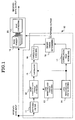
- Fig. 1 is a block diagram showing a preferred embodiment of the multi-path detecting circuit according to the present invention.
- the multi-path detecting circuit 10 according to the present invention comprises a matched filter 11, a short period delayed profile averaging part 12, a long period delayed profile averaging part 13, a long period delayed profile storing part 14, a subtracter 15, a threshold checking part 16, a correlation peak retrieving part 17 and a finger timing determining part 18.
- the output of the multi-path detecting circuit 10 is inputted together with received data input to an RAKE finger part 19.
- the output of the RAKE finger part 19 is inputted to an RAKE synthesizing part 20, which provides received data output.
- the received data input is inputted to the matched filter 11.
- the matched filter 11 is connected to the short delayed profile period averaging part 12.
- the short delayed profile period averaging part 12 is connected to the long delayed profile period averaging part 13 and also to the subtracter 15.
- the long delayed profile period averaging part 13 is connected via the long period delayed profile storing part 14 to the subtracter 15 and also to the correlation peak retrieving part 17.
- the subtracter 15 is connected via the threshold checking part 16 to the finger timing determining part 18.
- the correlation peak retrieving part 17 is also connected to the finger timing retrieving part 18.
- the multi-path detecting circuit shown in Fig. 1 features that it determines pathes to be allotted to RAKE finger by using in combination a long period averaged delayed profile for averaging level variations due to fading and a short period averaged delayed profile for fast detecting new path generation.
- the matched filter 11 outputs correlation value data concerning spread code and received signal.
- the short period delayed profile averaging part 12 thus averages delayed profile of measured channel path for such a short period that noise can be averaged.
- the long period delayed profile averaging part 13 further power averages the short period averaged delayed profile data for a long period, and outputs the power averaged data to the long period delayed profile storing part 14.
- the subtracter 15 subtracts a difference from the stored long period averaged delayed profile whenever the short period averaged delayed profile is outputted. When the difference exceeds a predetermined threshold value, the threshold checking part 16 outputs data of pathes to be added.
- the finger timing determining part 18 adds path allotment to the RAKE finger part 19 according to the output of the threshold checking part 16.
- the correlation peak retrieving part 16 retrieves correlation peaks up to upper rank N for every long period delayed profile storing part output.
- the part 18 allots these path timings to the RAKE finger part 19.
- N stands for number of fingers.
- the above operation is performed repeatedly for every two delayed profile averaging periods to estimate the multi-path timing of the propagation channel.
- the RAKE synthesizing part 20 synthesizes data received in the individual fingers with each multi-path. Thus, at such a low moving rate time as when the terminal user is walking, level variations due to low rate fading can be sufficiently averaged by the delayed profile averaging over the long period.
- Fig. 2 is a block diagram showing a CDMS receiver using the multi-path detecting circuit 10 shown in Fig. 1.
- the CDMA receiver 30 comprises an antenna part 21, a high frequency signal receiving circuit part 22 and an A/D (analog-to-digital) converter 23 as well as the RAKE finger part 19, the RAKE synthesizing part 20 and the multi-path detecting part 10 shown in Fig. 1.
- the antenna part 21 receives radio transmitted data.
- the high frequency signal receiving circuit (i.e., radio part) 22 frequency converts (i.e., down-converts) the received signal.
- the A/D converter part 23 converts the output of the circuit 22 from analog signal to digital signal.
- the multi-path detecting circuit 10 receives signal from the A/D converter part 23, and detects multi-path timing by measuring the delayed profile of the propagation channel.
- the output of the circuit 10 is used as reception timing input to the RKE finger part 19.
- the RAKE synthesizing part 20 synthesizes data from the RAKE finger part 19 as received at each timing.
- the multi-path detecting circuit 10 comprises the matched filter 11, which outputs the data of correlation of spread codes and received signal to one another.
- the short period delayed profile averaging part 12 averages the delayed profile of the propagation channel as measured by the matched filter 11 for such a short period of time as to be able to smooth noise.
- the long period delayed profile averaging part 13 power averages the short period averaged delayed profile data for a longer period of time, and outputs the resultant data to the long period delayed profile storing part 14.
- the subtracter 15 extracts the difference from the stored long period averaged delayed profile for every short period averaged delayed profile output.
- the threshold checking part 16 determines that a new path has been generated, and outputs data of pathes to be added. According to this output, the finger timing determining part 18 adds path allotment to the fingers.
- the correlation peak retrieving part 17 retrieves correlation peaks up to upper rank N for every long period delayed profile output. The part 18 allots these path timings to the RAKE finger part 19. The above operation is executed for every two delayed profile averaging periods, thus estimating the multi-path timing of the propagation channel.
- the multi-path timing data thus obtained is inputted (i.e., supplied) to the RAKE finger part 19 shown in Fig. 2.
- the multi-path detecting circuit 10 can obtain sufficient averaging of level variations due to slow fading by long period averaging the delayed profile. It is thus possible to obtain highly reliable path selection.
- the path positions are fast changed due to shadowing or like cases. Again in this case, it is possible to fast add path allotment to the fingers by the estimation according to the short period delayed profile. It is thus possible to obtain multi-path detection reliability improvement independently of the moving status of the terminal.
- the path selection according to the short period averaged delayed profile data requires only subtraction and threshold checking, it is possible to reduce the circuit scale and the current consumption.
- the matched filter 11 shown in Fig. 1 is well known to the person skilled in the art as delayed profile measuring means, and its detailed construction and operation are not described. It is possible to replace this part with a sliding correlator.
- the RAKE finger part 19 and the RAKE synthesizing part 20 are also well known to the person skilled in the art and have no direct bearing on the present invention, and their detailed construction and operation are not described.
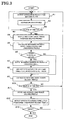
- the matched filter 11 executes instantaneous delayed profile profile measurement by calculating the correlation of spread codes and received signal to one another (step A1).
- This delayed profile is averaged for time T1 (for instance 10 msec.) such as to be able to smooth noise (step A2).
- a check is then performed as to whether the time T1 has elapsed (step A3).
- the result of the short period averaging is outputted (step A4).
- the difference of the stored long period averaged delayed profile correlation data from the output data obtained in the step A4 is calculated or extracted for each sample (step A5).
- step A6 a check is performed for each sample as to whether a predetermined threshold value has been exceeded.
- M sample numbers in excess of the threshold value are outputted (step A7).
- a finger allotment determining part allots newly detected new pathes are allotted to the fingers presently out of use or in the order of lower reception power level fingers (step A8).
- the above operation is executed in a cycle period of time T1.
- the detected pathes can be added in the time T1.
- the short period averaged delayed profile outputted in the step A4 is then averaged for longer period T2 of time (for instance 100 msec.) (step A9).
- a check is then performed as to whether time T2 has elapsed (step A10).
- the long period averaged delayed profile data is stored for every averaging period of the time T2 (step A11).
- Upper N to M rank correlation peaks of the stored profile are selected, and these timings are allotted to the fingers (step A12).
- N is the number of fingers
- M is the number of new peaks detected in the step A7.
- the above process is executed in a cycle period of the time T2.
- step A13 a check is performed as to whether the system has been inoperative (step A13). When “Yes” is yielded in the step A13, an end is brought to the routine. When “No” is yielded in the steps A10 and A13, the routine goes back to the step A1 noted above.
- Fig. 4 is a block diagram showing the construction of the different embodiment. This embodiment is the same in the basic construction as the preferred or first embodiment shown in Fig. 1. In Fig. 4, parts corresponding to those on Fig. 1 are designated by like reference numerals.
- the multi-path detecting circuit 10' shown in Fig. 4 is obtained by omitting the delayed profile storing part 14 and the subtracter 15 shown in Fig. 1 to reduce the necessary memory size. That is, the circuit 10' comprises the matched filter 11, the short period delayed profile averaging part 12, the long period delayed profile averaging part 13, the threshold checking part 16, the correlation peak retrieving part 17 and the finger timing determining part 18.
- the matched filter 11 receives received data input, and its output is inputted to the short period delayed profile averaging part 12.
- the short period delayed profile averaging part 12 is connected to the long period delayed profile averaging part 13 and the threshold checking part 16.
- the long period delayed profile delayed profile averaging part 13 is connected via the correlation peak retrieving part 17 to the finger timing determining part 18.
- the path timing output of the finger timing determining part 18 is inputted to the threshold checking part 16 and also to the RAKE finger part 19.
- the output of the RAKE finger part 19 is inputted to the RAKE synthesizing part 20, which in turn outputs received data output.
- Fig. 5 is a flow chart for describing the operation of the multi-path detecting circuit 10' shown in Fig. 4.
- the flow chart of Fig. 5, like the flow chart of Fig. 3, is constituted by steps B1 to B13, and main difference of the former chart from the later resides in that instead of the calculation of the difference between the long period averaged delayed profile data and the short period averaged data, the threshold checking part executes the threshold check by excluding the pathes presently allotted to the fingers and samples near the detected pathes from the short period delayed profile data (step B4).
- the threshold checking part executes the threshold check by excluding the pathes presently allotted to the fingers and samples near the detected pathes from the short period delayed profile data (step B4).
- the subtracting process on all the samples is simplified compared to the Fig. 4 embodiment.
- no long period averaged delayed profile storing part (or memory) is necessary.
- the multi-path detecting circuit As has been described in the foregoing, with the multi-path detecting circuit according to the present invention the following pronounced practical effects are obtainable.
- sufficient averaging of level variations due to slow fading is possible by long period averaging even at a slow moving time. It is thus possible to preferentially select high average reception power level pathes.
- the path existing positions is fast changes due to shadowing or like causes, it is possible to fast add path allotment to the fingers by the estimation from the short period delayed profile. It is thus possible to obtain multi-path detection reliability improvement independently of the moving status of the terminal.
- the path selection from the short period delayed profile requires only subtraction and threshold checking, it is possible to reduce the circuit scale and the current consumption.
Landscapes
- Engineering & Computer Science (AREA)
- Computer Networks & Wireless Communication (AREA)
- Signal Processing (AREA)
- Mobile Radio Communication Systems (AREA)
- Noise Elimination (AREA)
- Collating Specific Patterns (AREA)
- Monitoring And Testing Of Transmission In General (AREA)
Abstract
Description
Claims (10)
- A multi-path detecting circuit for detecting multi-path timings by measuring a delayed profile of a propagation channel, comprising:
a short period delayed profile averaging part and a long period delayed profile averaging part for averaging the delayed profile in two different, i.e., short and long, cycle periods, respectively. - The multi-path detecting circuit according to claim 1, further comprising a threshold checking part for receiving the output of the short period delayed profile averaging part and checking whether the output exceeds a threshold value, a correlation peak retrieving part for receiving the output of the long period delayed profile averaging part and retrieving upper rank correlation peaks for every correlation profile, and a finger timing determining part for receiving the outputs of the correlation peak retrieving part and the threshold checking part.
- The multi-path detecting circuit according to one of claims 1 and 2, comprising a long period profile storing part for storing the output of the long period delayed profile averaging part.
- The multi-path detecting circuit according to claim 3, comprising a subtracter provided between the short period delayed profile averaging part and the threshold checking part, for extracting the difference of the short period averaged delayed profile from the long period averaged delayed profile stored in the long period delayed profile storing part for each short period averaged delayed profile.
- The circuit according to any one of claims 1 to 4, wherein the short period is set to about 10 msec., and the long period is set to about 100 msec.
- The circuit according to any one of claims 1 to 5, which is used for a CDMA receiver having a RAKE finger part, to which the timing output from the finger timing determining part is supplied.
- A multi-path detecting system for determining pathes to be allotted to RAKE finger on the basis of combination of a long period averaged delayed profile for averaging level variations due to fading and a short period averaged delayed profile for fast detecting new path generation.
- A multi-path detecting system comprising:a matched filter for outputting correlation value data concerning spread code and received signal;a short period delayed profile averaging part for averaging delayed profile of measured channel path;a long period delayed profile averaging part for power averaging the short period averaged delayed profile data for a long period and storing the power averaged data to a long period delayed profile storing part;a subtracter for subtracting a difference from the stored long period averaged delayed profile whenever the short period averaged delayed profile is outputted;a threshold checking part for outputting data of pathes to be added when the difference from the subtracter exceeds a predetermined threshold value;a finger timing determining part for adding path allotment to RAKE finger part on the basis of the output of the threshold checking part;a correlation peak retrieving part for retrieving correlation peaks up to upper rank N for every long period delayed profile storing part output;a finger timing determining part for alloting the path timings to the RAKE finger part; anda RAKE synthesizing part for synthesizing data received in the individual fingers with each multi-path.
- A multi-path detecting system comprising steps of:executing instantaneous delayed profile profile measurement by calculating correlation of spread codes and received signal to one another;averaging the delayed profile for time such as to be able to smooth noise;checking as to whether the time has elapsed;outputting the result of the short period averaging after the averaging for the time;calculating the difference of the long period averaged delayed profile correlation data from the short period averaged data obtained for each sample;checking, for each sample, as to whether a predetermined threshold value has been exceeded and, when the threshold value has been exceeded , outputting M sample numbers in excess of the threshold value;alloting newly detected new pathes the fingers presently out of use or in the order of lower reception power level fingers.averaging the short period averaged delayed profile for longer period of time;checking as to whether the longer time has elapsed;storing the long period averaged delayed profile data for every averaging period of the longer time;selecting upper N to M rank correlation peaks of the stored profile; andalloting these timings to the fingers.
- A CDMS receiver using the multi-path detecting circuit according to any one of claims 1 to 6 or the multi-path detecting system according to any one of claims 7 to 9 comprising:an antenna part for receiving radio transmitted data;a high frequency signal receiving circuit for frequency converting the received signal;an A/D converter part for converting the output of the high frequency signal receiving circuit from analog signal to digital signal;the multi-path detecting circuit for receiving signal from the A/D converter part, detecting multi-path timing and determining the detected multi-path timing as reception timing input to RKE finger part; anda RAKE synthesizing part for synthesizing data from the RAKE finger part as received at each timing.
Applications Claiming Priority (2)
| Application Number | Priority Date | Filing Date | Title |
|---|---|---|---|
| JP2000106558A JP3440919B2 (en) | 2000-04-07 | 2000-04-07 | Multipath detection circuit |
| JP2000106558 | 2000-04-07 |
Publications (3)
| Publication Number | Publication Date |
|---|---|
| EP1143631A2 true EP1143631A2 (en) | 2001-10-10 |
| EP1143631A3 EP1143631A3 (en) | 2003-02-19 |
| EP1143631B1 EP1143631B1 (en) | 2006-06-07 |
Family
ID=18619706
Family Applications (1)
| Application Number | Title | Priority Date | Filing Date |
|---|---|---|---|
| EP20010108778 Expired - Lifetime EP1143631B1 (en) | 2000-04-07 | 2001-04-06 | Multi-path detecting circuit, system and method |
Country Status (6)
| Country | Link |
|---|---|
| US (1) | US20010028676A1 (en) |
| EP (1) | EP1143631B1 (en) |
| JP (1) | JP3440919B2 (en) |
| CN (1) | CN1170387C (en) |
| DE (1) | DE60120269T2 (en) |
| HK (1) | HK1042607A1 (en) |
Cited By (3)
| Publication number | Priority date | Publication date | Assignee | Title |
|---|---|---|---|---|
| EP1523108A1 (en) * | 2003-10-08 | 2005-04-13 | Nec Corporation | Method and apparatus for CDMA signal reception |
| EP1519494A3 (en) * | 2003-08-25 | 2006-10-25 | Sharp Kabushiki Kaisha | CDMA multipath reception |
| GB2493161A (en) * | 2011-07-26 | 2013-01-30 | St Microelectronics Res & Dev | Multi path detection |
Families Citing this family (9)
| Publication number | Priority date | Publication date | Assignee | Title |
|---|---|---|---|---|
| JP3421314B2 (en) * | 2000-10-04 | 2003-06-30 | 松下電器産業株式会社 | Path selection device and path selection method |
| US7103090B2 (en) * | 2001-08-13 | 2006-09-05 | Mediatek Inc. | Timing estimation of direct sequence spread spectrum communications systems over frequency-selective, slowly fading channels |
| JP3565199B2 (en) * | 2001-10-19 | 2004-09-15 | 日本電気株式会社 | CDMA receiver, base station, mobile terminal, path selection method and program |
| US7023902B2 (en) * | 2001-11-06 | 2006-04-04 | Qualcomm Inc. | Apparatus and method for scalable offline CDMA demodulation |
| JP4389704B2 (en) * | 2004-07-16 | 2009-12-24 | 日本電気株式会社 | CDMA receiver and synchronization timing detection method in CDMA receiver |
| CN102158436B (en) * | 2010-02-11 | 2014-01-08 | 富士通株式会社 | Channel Frequency Domain Correlation Calculation Method and Device, Channel Estimation Method and Device |
| JP2012165064A (en) * | 2011-02-03 | 2012-08-30 | Sharp Corp | Receiver, reception method, reception program, and communication system |
| US12063063B2 (en) * | 2021-09-16 | 2024-08-13 | L3Harris Technologies, Inc. | Rake receiver and related methods |
| CN114070779B (en) * | 2021-11-25 | 2023-08-29 | 群联电子股份有限公司 | Clock reforming circuit module, signal transmission system and signal transmission method |
Family Cites Families (15)
| Publication number | Priority date | Publication date | Assignee | Title |
|---|---|---|---|---|
| US5627863A (en) * | 1994-07-15 | 1997-05-06 | Amati Communications Corporation | Frame synchronization in multicarrier transmission systems |
| US6240124B1 (en) * | 1995-06-06 | 2001-05-29 | Globalstar L.P. | Closed loop power control for low earth orbit satellite communications system |
| US5790514A (en) * | 1996-08-22 | 1998-08-04 | Tellabs Operations, Inc. | Multi-point OFDM/DMT digital communications system including remote service unit with improved receiver architecture |
| JPH1093762A (en) * | 1996-09-18 | 1998-04-10 | Fuji Photo Film Co Ltd | Image data storing method and device therefor |
| US5844949A (en) * | 1996-10-09 | 1998-12-01 | General Electric Company | Power line communication system |
| JPH10190528A (en) * | 1996-12-25 | 1998-07-21 | Matsushita Electric Ind Co Ltd | Spread spectrum receiver |
| US6163563A (en) * | 1996-12-31 | 2000-12-19 | Lucent Technologies Inc. | Digital communication system for high-speed complex correlation |
| JP2850959B2 (en) * | 1997-05-12 | 1999-01-27 | 日本電気株式会社 | Spread spectrum communication synchronous acquisition demodulator |
| JP2856198B2 (en) * | 1997-06-11 | 1999-02-10 | 日本電気株式会社 | Spread spectrum receiver |
| US6389062B1 (en) * | 1997-09-17 | 2002-05-14 | Texas Instruments Incorporated | Adaptive frequency domain equalizer circuits, systems, and methods for discrete multitone based digital subscriber line modem |
| US6075821A (en) * | 1997-12-16 | 2000-06-13 | Integrated Telecom Express | Method of configuring and dynamically adapting data and energy parameters in a multi-channel communications system |
| JP3891373B2 (en) * | 1998-03-26 | 2007-03-14 | ソニー株式会社 | Demodulator and demodulation method |
| US6370397B1 (en) * | 1998-05-01 | 2002-04-09 | Telefonaktiebolaget Lm Ericsson (Publ) | Search window delay tracking in code division multiple access communication systems |
| US6603811B1 (en) * | 1998-05-29 | 2003-08-05 | 3Com Corporation | Low complexity frequency domain equalizer having fast re-lock |
| JP3571978B2 (en) | 1999-11-18 | 2004-09-29 | 株式会社エヌ・ティ・ティ・ドコモ | Path selection device, reception device, and path selection method |
-
2000
- 2000-04-07 JP JP2000106558A patent/JP3440919B2/en not_active Expired - Fee Related
-
2001
- 2001-04-06 CN CNB011105038A patent/CN1170387C/en not_active Expired - Fee Related
- 2001-04-06 EP EP20010108778 patent/EP1143631B1/en not_active Expired - Lifetime
- 2001-04-06 DE DE2001620269 patent/DE60120269T2/en not_active Expired - Lifetime
- 2001-04-09 US US09/828,237 patent/US20010028676A1/en not_active Abandoned
-
2002
- 2002-03-28 HK HK02102390.0A patent/HK1042607A1/en unknown
Cited By (7)
| Publication number | Priority date | Publication date | Assignee | Title |
|---|---|---|---|---|
| EP1519494A3 (en) * | 2003-08-25 | 2006-10-25 | Sharp Kabushiki Kaisha | CDMA multipath reception |
| US7519107B2 (en) | 2003-08-25 | 2009-04-14 | Sharp Kabushiki Kaisha | CDMA receiving apparatus, method, program and recording medium |
| EP1523108A1 (en) * | 2003-10-08 | 2005-04-13 | Nec Corporation | Method and apparatus for CDMA signal reception |
| US7292609B2 (en) | 2003-10-08 | 2007-11-06 | Nec Corporation | Method and apparatus for CDMA signal reception |
| GB2493161A (en) * | 2011-07-26 | 2013-01-30 | St Microelectronics Res & Dev | Multi path detection |
| US9236903B2 (en) | 2011-07-26 | 2016-01-12 | Stmicroelectronics (Research & Development) Limited | Multi-path detection |
| GB2493161B (en) * | 2011-07-26 | 2017-05-10 | Stmicroelectronics (Research & Development) Ltd | Multi-path detection |
Also Published As
| Publication number | Publication date |
|---|---|
| JP3440919B2 (en) | 2003-08-25 |
| DE60120269D1 (en) | 2006-07-20 |
| US20010028676A1 (en) | 2001-10-11 |
| CN1317893A (en) | 2001-10-17 |
| EP1143631B1 (en) | 2006-06-07 |
| EP1143631A3 (en) | 2003-02-19 |
| JP2001292076A (en) | 2001-10-19 |
| DE60120269T2 (en) | 2006-10-19 |
| CN1170387C (en) | 2004-10-06 |
| HK1042607A1 (en) | 2002-08-16 |
Similar Documents
| Publication | Publication Date | Title |
|---|---|---|
| AU760220B2 (en) | CDMA receiver, path detection method and recording medium on which path detection control program is recorded | |
| US6731622B1 (en) | Multipath propagation delay determining means using periodically inserted pilot symbols | |
| KR100274715B1 (en) | Spread spectrum receiver and transmission power control method | |
| EP1096711B1 (en) | CDMA receiving method and circuit | |
| EP1143631B1 (en) | Multi-path detecting circuit, system and method | |
| KR100694927B1 (en) | Multipath propagation delay determination device using pilot symbols inserted periodically | |
| US6763056B1 (en) | Path timing detection circuit and detection method thereof | |
| MXPA01013040A (en) | Method and apparatus for fast wcdma acquisition. | |
| WO2004028018A1 (en) | Assessment of delay estimation quality using interference estimates | |
| EP1527526A1 (en) | Power measurement of received cdma signals using soft threshold preprocessing after correlation | |
| EP1065795A2 (en) | CDMA communication terminal apparatus and radio reception method | |
| EP1628409B1 (en) | A power level measuring device and a mobile station | |
| JP2003347968A (en) | Path position detecting method and cdma receiver | |
| JP2003110459A (en) | Wireless receiving apparatus and wireless receiving method | |
| JPH08223108A (en) | Fading pitch estimation device | |
| EP1137193A2 (en) | Method and circuit for delay profile measurement | |
| JPH10112672A (en) | Spread spectrum communication receiver | |
| JP2004104575A (en) | Path timing detector | |
| JP4431601B2 (en) | Receiver for detecting path timing | |
| JP2001274726A (en) | Spread spectrum receiving apparatus and spread spectrum receiving method | |
| JPH0879161A (en) | Fading pitch estimation device | |
| KR19990015327A (en) | Initial Synchronization Recognition Method of Pseudo Noise Code |
Legal Events
| Date | Code | Title | Description |
|---|---|---|---|
| PUAI | Public reference made under article 153(3) epc to a published international application that has entered the european phase |
Free format text: ORIGINAL CODE: 0009012 |
|
| AK | Designated contracting states |
Kind code of ref document: A2 Designated state(s): AT BE CH CY DE DK ES FI FR GB GR IE IT LI LU MC NL PT SE TR |
|
| AX | Request for extension of the european patent |
Free format text: AL;LT;LV;MK;RO;SI |
|
| PUAL | Search report despatched |
Free format text: ORIGINAL CODE: 0009013 |
|
| AK | Designated contracting states |
Designated state(s): AT BE CH CY DE DK ES FI FR GB GR IE IT LI LU MC NL PT SE TR |
|
| AX | Request for extension of the european patent |
Extension state: AL LT LV MK RO SI |
|
| 17P | Request for examination filed |
Effective date: 20030110 |
|
| AKX | Designation fees paid |
Designated state(s): DE FR GB IT |
|
| 17Q | First examination report despatched |
Effective date: 20040713 |
|
| GRAP | Despatch of communication of intention to grant a patent |
Free format text: ORIGINAL CODE: EPIDOSNIGR1 |
|
| RTI1 | Title (correction) |
Free format text: MULTI-PATH DETECTING CIRCUIT, SYSTEM AND METHOD |
|
| GRAS | Grant fee paid |
Free format text: ORIGINAL CODE: EPIDOSNIGR3 |
|
| GRAA | (expected) grant |
Free format text: ORIGINAL CODE: 0009210 |
|
| AK | Designated contracting states |
Kind code of ref document: B1 Designated state(s): DE FR GB IT |
|
| PG25 | Lapsed in a contracting state [announced via postgrant information from national office to epo] |
Ref country code: IT Free format text: LAPSE BECAUSE OF FAILURE TO SUBMIT A TRANSLATION OF THE DESCRIPTION OR TO PAY THE FEE WITHIN THE PRESCRIBED TIME-LIMIT;WARNING: LAPSES OF ITALIAN PATENTS WITH EFFECTIVE DATE BEFORE 2007 MAY HAVE OCCURRED AT ANY TIME BEFORE 2007. THE CORRECT EFFECTIVE DATE MAY BE DIFFERENT FROM THE ONE RECORDED. Effective date: 20060607 |
|
| REG | Reference to a national code |
Ref country code: GB Ref legal event code: FG4D |
|
| REF | Corresponds to: |
Ref document number: 60120269 Country of ref document: DE Date of ref document: 20060720 Kind code of ref document: P |
|
| ET | Fr: translation filed | ||
| PLBE | No opposition filed within time limit |
Free format text: ORIGINAL CODE: 0009261 |
|
| STAA | Information on the status of an ep patent application or granted ep patent |
Free format text: STATUS: NO OPPOSITION FILED WITHIN TIME LIMIT |
|
| 26N | No opposition filed |
Effective date: 20070308 |
|
| PGFP | Annual fee paid to national office [announced via postgrant information from national office to epo] |
Ref country code: GB Payment date: 20140402 Year of fee payment: 14 |
|
| PGFP | Annual fee paid to national office [announced via postgrant information from national office to epo] |
Ref country code: IT Payment date: 20140418 Year of fee payment: 14 Ref country code: DE Payment date: 20140430 Year of fee payment: 14 Ref country code: FR Payment date: 20140409 Year of fee payment: 14 |
|
| REG | Reference to a national code |
Ref country code: GB Ref legal event code: 732E Free format text: REGISTERED BETWEEN 20141023 AND 20141029 |
|
| REG | Reference to a national code |
Ref country code: FR Ref legal event code: TP Owner name: LENOVO INNOVATIONS LIMITED (HONG KONG), HK Effective date: 20141119 |
|
| REG | Reference to a national code |
Ref country code: DE Ref legal event code: R119 Ref document number: 60120269 Country of ref document: DE |
|
| GBPC | Gb: european patent ceased through non-payment of renewal fee |
Effective date: 20150406 |
|
| PG25 | Lapsed in a contracting state [announced via postgrant information from national office to epo] |
Ref country code: IT Free format text: LAPSE BECAUSE OF NON-PAYMENT OF DUE FEES Effective date: 20150406 Ref country code: GB Free format text: LAPSE BECAUSE OF NON-PAYMENT OF DUE FEES Effective date: 20150406 Ref country code: DE Free format text: LAPSE BECAUSE OF NON-PAYMENT OF DUE FEES Effective date: 20151103 |
|
| REG | Reference to a national code |
Ref country code: FR Ref legal event code: ST Effective date: 20151231 |
|
| PG25 | Lapsed in a contracting state [announced via postgrant information from national office to epo] |
Ref country code: FR Free format text: LAPSE BECAUSE OF NON-PAYMENT OF DUE FEES Effective date: 20150430 |