JP3565199B2 - CDMA receiver, base station, mobile terminal, path selection method and program - Google Patents
CDMA receiver, base station, mobile terminal, path selection method and program Download PDFInfo
- Publication number
- JP3565199B2 JP3565199B2 JP2001321568A JP2001321568A JP3565199B2 JP 3565199 B2 JP3565199 B2 JP 3565199B2 JP 2001321568 A JP2001321568 A JP 2001321568A JP 2001321568 A JP2001321568 A JP 2001321568A JP 3565199 B2 JP3565199 B2 JP 3565199B2
- Authority
- JP
- Japan
- Prior art keywords
- path
- paths
- selection
- range
- circuit
- Prior art date
- Legal status (The legal status is an assumption and is not a legal conclusion. Google has not performed a legal analysis and makes no representation as to the accuracy of the status listed.)
- Expired - Fee Related
Links
Images


Classifications
-
- H—ELECTRICITY
- H04—ELECTRIC COMMUNICATION TECHNIQUE
- H04B—TRANSMISSION
- H04B1/00—Details of transmission systems, not covered by a single one of groups H04B3/00 - H04B13/00; Details of transmission systems not characterised by the medium used for transmission
- H04B1/69—Spread spectrum techniques
- H04B1/707—Spread spectrum techniques using direct sequence modulation
- H04B1/7097—Interference-related aspects
- H04B1/711—Interference-related aspects the interference being multi-path interference
- H04B1/7113—Determination of path profile
-
- H—ELECTRICITY
- H04—ELECTRIC COMMUNICATION TECHNIQUE
- H04B—TRANSMISSION
- H04B1/00—Details of transmission systems, not covered by a single one of groups H04B3/00 - H04B13/00; Details of transmission systems not characterised by the medium used for transmission
- H04B1/69—Spread spectrum techniques
- H04B1/707—Spread spectrum techniques using direct sequence modulation
- H04B1/7097—Interference-related aspects
- H04B1/711—Interference-related aspects the interference being multi-path interference
- H04B1/7115—Constructive combining of multi-path signals, i.e. RAKE receivers
- H04B1/7117—Selection, re-selection, allocation or re-allocation of paths to fingers, e.g. timing offset control of allocated fingers
Description
【0001】
【発明の属する技術分野】
本発明は、CDMA(Code Division Multiple Access) 受信装置に関し、特に、RAKE合成の対象にするパス間の遅延時間差を、サーチャー回路のパス測定範囲よりも短い一定の範囲内に収めるようにしたCDMA受信装置に関する。
【0002】
【従来の技術】
CDMA方式では、図9に示すようなマルチパス環境下(周波数選択性フェージング環境下)でも効率の良い通信を実現するため、基地局(或いは携帯端末)においては、図10に示すような遅延時間差を有する信号(パス)を、図11に示すように時間的にずらしながら合成するRAKE合成受信を行っている。
【0003】
図12に基地局や携帯端末で使用されている従来のCDMA受信装置の構成例を示す。同図に示すように、従来のCDMA受信装置は、無線受信部101と、サーチャー回路102と、RAKE合成回路103と、信号復号回路104とから構成されている。
【0004】
無線受信部101は、受信信号に対する周波数変換,AD変換を行う。サーチャー回路102は、無線受信部101の出力に基づいて遅延プロファイル(遅延時間に対する信号電力分布)を測定し、この遅延プロファイルに基づいてパス測定範囲内に存在するパスの内の幾つかを選択する。そして、選択したパスのタイミング(遅延時間)を示すタイミング情報をRAKE合成回路103に通知する。RAKE合成回路103では、通知されたタイミング情報に従って各パス毎に逆拡散を行い、RAKE合成を行う。RAKE合成回路103から出力されるデータ系列は、信号復号回路104において、誤り訂正復号される。
【0005】
ここで、RAKE合成を行うRAKE合成回路103は、受信電力を高め通信品質を向上させるために、なるべく多くのパスを合成できるものであることが望ましい。しかし、現実的には、回路規模の制限から合成できるパス数が制限される。このため、従来は、一般に、下記A〜Cの何れかの方法を用いて、パス測定範囲内に存在するパスの中からRAKE合成回路103で合成対象にするパスを幾つか選択するようにしている。
【0006】
A.レベルが大きい方から所定個数のパスを選択する(例えば、特開2000−101549 号公報の従来の技術の項)。
【0007】
B.遅延プロファイルの平均電力値等に基づいて閾値を決定し、この閾値よりもレベルが大きいパスを選択する(例えば、特開2000−101549 号公報)。
【0008】
C.主波(例えば、受信機に最初に到達したパス)の近傍に存在するパスから順番にレベルが閾値以上であるか否かを判定し、閾値以上のパスを所定個数選択する(例えば、特開2001−186056 号公報)。
【0009】
【発明が解決しようとする課題】
上述した方法A〜Cによれば、レベルの高いパスが選択されるため、受信電力を高いものにし、通信品質を高いものにすることができる。しかし、方法A〜Cの内、方法A,Bは、パスのレベルのみに注目して合成対象にするパスを選択しているため、選択されたパスの中に、遅延時間差が大きなものとなるパスの組み合わせが含まれる場合がある。上記遅延時間差の最大値は、サーチャー回路102のパス測定範囲に相当する時間となる。また、Cの方法は、主波から外側に向かって、レベルが閾値以上のパスを所定個数選択するようにしているが、この方法によっても選択されたパスの中に、遅延時間差がサーチャー回路102のパス測定範囲と同じになるパスの組み合わせが含まれる場合がある。
【0010】
このように、従来方法A〜Cで合成対象パスを選択すると、選択したパスの中に遅延時間差がサーチャー回路102のパス測定範囲と同じになるパスの組み合わせが含まれる場合がある。従って、従来方法A〜Cで選択されたパスをRAKE合成するRAKE合成回路103は、遅延時間差がサーチャー回路のパス測定範囲と同じになる、遅延時間差が大きなパスの組み合わせもRAKE合成できるものでなければならない。RAKE合成回路103の回路規模は、RAKE合成することが可能なパスの遅延時間差が大きくなるほど大きくなるため、従来方法A〜Cで合成対象パスを選択するようにすると、RAKE合成回路103の回路規模が大きくなってしまうという問題がある。例えば、図13に示すような、拡散符号発生器131,遅延回路132,受信信号遅延バッファ133,合成回路134および相関器135から構成されるRAKE合成回路に於いては、RAKE合成可能なパスの遅延時間差が大きくなると、受信信号遅延バッファ133の回路規模が大きくなってしまう。
【0011】
そこで、本発明の目的は、通信品質を保ち、且つRAKE合成回路の回路規模を小さくすることができるCDMA受信装置を提供することにある。
【0012】
【課題を解決するための手段】
本発明のCDMA受信装置は、上記目的を達成するため、サーチャー回路のパス測定範囲内に存在する両端のパス(遅延時間差が最も大きいパス)の内の、レベルの小さい方のパスを選択対象から除外するという処理を、除外されずに残っているパスの存在範囲が、RAKE合成回路の合成範囲(パス測定範囲よりも狭い)内となるまで繰り返し行う。そして、合成範囲内に存在することになったパスを、RAKE構成回路における合成対象パスとする。この構成によれば、サーチャー回路のパス測定範囲内に存在するパスの内の連続するパスが、RAKE合成回路における合成対象パスとして選択されるので、合成対象パスの遅延時間差を従来の技術に比較して小さくすることができる。この結果、RAKE合成回路の回路規模を従来よりも小さくすることができる。また、両端のパスの内、レベルの高い方を残しているので、受信電力を高いものにし、通信品質を保つことができる。
【0013】
より具体的には、本発明のCDMA受信装置は、
電波伝播上の遅延プロファイルを測定する測定手段と、
該測定手段の測定結果に基づいて、パス測定範囲内に存在する両端のパスの内のレベルが低い方のパスを選択対象から外すという処理を、選択対象として残ったパスの存在範囲が前記合成範囲内となるまで繰り返し行うパス選定回路とを含むサーチャー回路を備えている。
【0014】
また、本発明のCDMA受信装置は、ノイズの影響を少なくするため、
前記パス選定回路が、
前記両端のパスのレベルが同じ場合は、前記両端のパスそれぞれについて、隣接する内側パスとの遅延時間差を求め、両端のパスの内の遅延時間差が大きい方のパスを選択対象から外す構成を有している。
【0015】
図14(A),(B),(C)は、それぞれ田舎,丘,都会に於ける伝播モデルを示している。同図(A)〜(C)から分かるように、パスは集中して存在しており、若し、隣接パスとの遅延時間差が大きいパスが存在していれば、それはノイズである可能性が高い。従って、遅延時間差の大きなパスを選択対象から除外することにより、ノイズの影響を少なくすることができる。
【0016】
また、本発明は、サーチャー回路の処理時間を短縮させるため、
前記パス測定範囲内に存在するレベルが閾値以上のパスを対象にし、両端のパスの内のレベルが低い方のパスを選択対象から外すという処理を、選択対象として残ったパスの存在範囲が前記パス測定範囲よりも狭い、前記RAKE合成回路における合成範囲内となるまで繰り返し行う。
【0017】
この構成によれば、レベルが閾値以上のパスのみが処理対象になるので、サーチャー回路の処理時間を短縮することが可能になる。
【0018】
【発明の実施の形態】
次に本発明の実施の形態について図面を参照して詳細に説明する。
【0019】
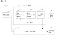
図1は本発明に係るCDMA受信装置の実施例のブロック図である。同図に示すように、本実施例のCDMA受信装置は、無線受信部1と、サーチャー回路2と、RAKE合成回路3と、信号復号回路4とを備えている。
【0020】
無線受信部1は、受信した信号をIF周波数に周波数変換した後、AD変換する機能を有する。
【0021】
サーチャー回路2は、RAKE合成回路3で合成対象にするパス(復調対象にするパス)を選択する機能を有するものであり、例えば、DSP(ディジタルシグナルプロセッサ)により構成される。本実施例のサーチャー回路2は、遅延プロファイル測定部21と、遅延プロファイル記憶部22と、パス選定回路23と、記録媒体K1とを備えている。
【0022】
遅延プロファイル測定部21は、パス測定範囲内に存在する各パスの遅延時間及びレベルを示す遅延プロファイルを測定し、測定結果を遅延プロファイル記憶部22に格納する機能や、遅延プロファイルの測定が完了したとき、パス選定回路23に完了通知を送る機能を有する。
【0023】
パス選定回路23は、遅延プロファイル記憶部22の内容に基づいて、パス測定範囲内に存在する各パスの内の、破棄されておらず且つ遅延時間差が最も大きい2つのパス(両端のパス)のレベルを比較し、レベルの小さい方のパスを破棄するという処理を、破棄されていないパスが存在する範囲がRAKE合成回路の合成範囲(パス測定範囲よりも狭い)内となるまで繰り返し行う機能や、残ったパスを合成対象パスとし、各合成対象パスを示すタイミング情報(遅延時間)をRAKE合成回路3に出力する機能を有する。更に、パス選定回路23は、両端のパスのレベルが同じ場合は、両端のパスそれぞれについて、内側パスとの遅延時間差を求め、両端のパスの内、内側パスとの遅延時間差の大きい方のパスを破棄する機能を有する。更に、パス選定回路23は、両端のパスの、内側パスとの遅延時間差が等しい場合は、両端のパスの内の、内側パスのレベルが低い方を破棄する機能を有する。
【0024】
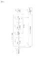
このような機能を有するパス選定回路23は、例えば、図2のブロック図に示す構成を有する。同図に示すように、パス選定回路23は、範囲判定手段231と、パス情報記憶部232と、タイミング情報作成手段233と、レベル比較手段234と、遅延時間差比較手段235とを備えている。
【0025】
範囲判定手段231は、次の機能を有する。
【0026】
・遅延プロファイル測定手段21から完了通知が送られてきたとき、遅延プロファイル記憶部22の内容をパス情報記憶部232にコピーする機能。
・遅延プロファイル記憶部22の内容のコピーが完了したとき、及び遅延時間差比較手段235から遅延時間差が同じであることが通知されたとき、レベル比較手段234に対して、レベルを比較する2個のパスを示す情報(例えば、両端のパスとか、両端のパスそれぞれに対する第n番目の内側パス等)を含む比較指示を出力する機能。
・レベル比較手段234からレベルが同じであることが通知されたとき、遅延時間差比較手段235に対して、遅延時間差を求める内側パスを示す情報(例えば、両端のパスそれぞれに対する第m番目の内側パス等)を含む比較指示を出力する機能。
・レベル比較手段234,遅延時間差比較手段235からパス情報を削除したことが通知されたとき、パス情報記憶部232の内容に基づいて、破棄されずに残っているパスの存在範囲が、合成範囲内になったか否かを判定する機能。
・破棄されずに残っているパスの存在範囲が、合成範囲内であると判定した場合、タイミング情報作成手段233に対してタイミング情報の作成指示を出力する機能。
【0027】
レベル比較手段234は、次の機能を有する。
【0028】
・範囲判定手段231から比較指示が送られてきたとき、パス情報記憶部232の内容に基づいて、上記比較指示に含まれている情報によって示されている2個のパスのレベルを比較する機能。
・上記2個のパスのレベルが同一の場合、そのことを範囲判定手段231に通知する機能。
・上記2個のパスのレベルが同一でない場合、レベルが小さい方のパスに関するパス情報をパス情報記憶部232から削除し、そのことを範囲判定手段231に通知する機能。
【0029】
遅延時間差比較手段235は、次の機能を有する。
【0030】
・範囲判定手段231から比較指示が送られてきたとき、両端のパスそれぞれについて、上記比較指示に含まれている情報によって示されている内側パスとの遅延時間差を求め、両者を比較する機能。
・両端のパスの、内側パスとの遅延時間差が同一である場合、そのことを範囲判定手段231に通知する機能。
・両端のパスの、内側パスとの遅延時間差が同一でない場合、両端のパスの内、遅延時間差が大きい方のパスに関するパス情報をパス情報記憶部232から削除し、そのことを範囲判定手段231に通知する機能。
【0031】
タイミング情報作成手段233は、パス情報記憶部232にパス情報が格納されているパスそれぞれを、RAKE合成回路3における合成対象パスとするためのタイミング情報(遅延時間)を作成し、それをRAKE合成回路3に出力する機能を有する。尚、RAKE合成回路3内に存在するフィンガ部(図示せず)の数が、パス情報記憶部232にパス情報が格納されているパスの数よりも少ない場合は、パス情報が格納されているパスの内、レベルが高い方からフィンガ部の数と同じ数のパスを選択し、それを合成対象パスとする。
【0032】
再び図1に戻り、RAKE合成回路3は、パス選定回路23から通知されたタイミング情報によって示される各パス毎に逆拡散を行い、RAKE合成を行う機能を有する。
【0033】
信号復号回路4は、RAKE合成回路3から出力されるデータ系列に対して誤り訂正復号等を行う機能を有する。
【0034】
記録媒体K1は、半導体メモリ,ディスク,その他の記録媒体であり、DSPをサーチャー回路2として機能させるためのプログラムが記録されている。このプログラムは、DSPによって読み取られ、その動作を制御することで、DSP上に、遅延プロファイル測定部21,パス選定回路23を実現する。
【0035】
【実施例の動作】
次の本実施例の動作について詳細に説明する。
【0036】
サーチャー回路2内の遅延プロファイル測定部21は、パス測定範囲内に存在する各パスの遅延時間及びレベルを示す遅延プロファイルを測定し、測定結果を遅延プロファイル記憶部22に格納する。その後、遅延プロファイル測定部21は、パス選定回路23に対して遅延プロファイルの測定が完了したことを通知する。
【0037】
これにより、パス選定回路23内の、範囲判定手段231は、遅延プロファイル記憶部22の内容をパス情報記憶部232にコピーする(図3,S31)。この結果、パス情報記憶部232には、サーチャー回路2のパス測定範囲内に存在する各パスのパス情報(レベル及び遅延時間)が格納されることになる。その後、範囲判定手段231は、パス情報記憶部232の内容に基づいて、破棄されずに残っているパスの存在範囲が、サーチャー回路2の測定範囲よりも狭い合成範囲内に収まっているか否かを判断する(S32)。
【0038】
今、例えば、ステップS31おいて、図4(A)に示す各パスP1〜P5のパス情報がパス情報記憶部232に格納されたとする。この場合、パスP1〜P5の存在範囲は、合成範囲内に収まらないので、ステップS32の判断結果はNOとなる。ステップS32の判断結果がNOとなると、範囲判定手段231は、レベル比較手段234に対して、両端のパスP1,P5のレベルを比較することを指示する。
【0039】
これにより、レベル比較手段234は、パス情報記憶部232を参照し、パスP1,P5のレベルを比較する(S33)。図4の例の場合、P1<P5であるので、レベル比較手段234は、パス情報記憶部232からパスP1のパス情報を破棄(削除)することによりパスP1を選択対象から除外し、そのことを範囲判定手段231に通知する(S34がNO,S35)。
【0040】
これにより、範囲判定手段231は、パス情報記憶部232の内容を参照し、破棄されずに残っているパスP2〜P5の存在範囲が、合成範囲内であるか否かを判定する(S32)。このとき、図4(B)に示すように、パスP2〜P5の存在範囲は、合成範囲内に収まらないので、ステップS32の判断結果はNOとなる。この結果、レベル比較手段234において、両端のパスP2,P5のレベルが比較され、レベルが小さい方のパスP5のパス情報がパス情報記憶部232から破棄される(S33,S34がNO,S35)。パスP5が破棄されると、図4(B)に示すように、破棄されずに残っているパスP2〜P4の存在範囲が、合成範囲内となるので(S32がYES)、範囲判定手段231は、タイミング情報作成手段233に対してタイミング情報の作成指示を出力する。
【0041】
これにより、タイミング情報作成手段233は、パス情報記憶部232に格納されているパスP2〜P4のパス情報に基づいて、上記各パスP2〜P4をRAKE合成回路3で合成させるためのタイミング情報を作成し、RAKE合成回路3に出力する(S36)。これにより、RAKE合成回路3は、タイミング情報に従ってパスP2〜P4を合成する。
【0042】
図4に示した例では、ステップS34の判断結果がYESとなることはなかったが、例えば、S31において、図5に示す各パスP11〜P16(両端のパスP11,P16のレベルは同一)のパス情報がパス情報記憶部232に格納された場合は、S34の判断結果はYESとなる。
【0043】
図5の例の場合、パスP11〜P16の存在範囲は合成範囲に収まらず、両端のパスP11,P16のレベルは同一であるので、ステップS32,S34の判断結果はそれぞれNO,YESとなる。ステップS34の判断結果がYESとなると、レベル比較手段234は、範囲判定手段231に対して、両端のパスP11,P16のレベルが同一であることを通知する。
【0044】
これにより、範囲判定手段231は、遅延時間差比較手段235に対して、比較指示を出力する。この比較指示には、両端のパスP11,P16との遅延時間差を求めるパスが、両端のパスP11,P16から内側に向かって第1番目の内側パス(隣接パス)P12,PI5であることを示す情報が含まれている。
【0045】
遅延時間差比較手段235は、上記比較指示が与えられると、パスP11,P12間の遅延時間差と、パスP15,P16間の遅延時間差を求め、両者を比較する(S37)。この例の場合、パスP15,P16間の遅延時間差の方が大きいので、遅延時間差比較手段235は、パス情報記憶部232に格納されているパスP16のパス情報を破棄し、そのことを範囲判定手段231に通知する(S38がNO,S39)。
【0046】
上記通知を受けると、範囲判定手段231は、パス情報記憶部232を参照し、廃棄されずに残っているパスP11〜P15の存在範囲が、合成範囲内であるか否かを判断する(S32)。この図5の例の場合、パスP11〜P15の存在範囲は合成範囲内に収まるので(S32がYES)、範囲判定手段231は、タイミング情報作成手段233に対してタイミング情報の作成指示を出力する。これにより、タイミング情報作成手段233は、パスP11〜P15を示すタイミング情報を作成し、RAKE合成回路3に出力する(S36)。
【0047】
図4,図5の例では、ステップS38の判断結果がYESとなることはなかったが、例えば、S31において、図6に示す各パスP21〜P26(両端のパスP21,P26のレベルが同一で、且つ隣接パスP22,P25も同一条件)のパス情報がパス情報記憶部232に格納された場合は、S38の判断結果はYESとなる。
【0048】
図6の例の場合、パスP21〜P26の存在範囲は合成範囲内に収まらず、両端のパスP21,P26のレベルが等しいので、ステップS32,S34の判断結果は、それぞれNO,YESとなる。ステップS34の判断結果がYESとなると、レベル比較手段234は、範囲判定手段231に対して両端のパスP21,P26のレベルが同一であることを通知する。
【0049】
この通知を受けると、範囲判定手段231は、遅延時間差比較手段235に対して、両端のパスP21,P26の、第1番目の内側パスP22,P25との遅延時間差を比較することを指示する。これにより、遅延時間差比較手段235は、パスP21,P22間の遅延時間差とパスP25,P26間の遅延時間差とを求め、両者を比較する(S37)。この例の場合、遅延時間差が同一であるので、ステップS38の判断結果がYESとなり、遅延時間差比較手段235が、範囲判定手段235に対して遅延時間差が同一であることを通知する。
【0050】
この通知を受けると、範囲判定手段231は、レベル比較手段234に対して第1番目の内側パスP22,P25のレベルを比較することを指示する。これにより、レベル比較手段234は、第1番目の内側パスP22,P25のレベルを比較する(S40)。この例の場合、パスP22,P25のレベルが等しいので(S41がYES)、レベル比較手段234は、第1番目の内側パスP22,P25のレベルが等しいことを範囲判定手段231に通知する。
【0051】
この通知を受けると、範囲判定手段231は、次の内側パス(第2番目の内側パス)P23,P24がクロスするか否かを判断する(S43)。ここで、クロスするとは、左端のパスに対する第n番目の内側パスが、右端のパスに対する第n番目の内側パスよりも右端のパスに近くなったことをいう。この例の場合、第2番目の内側パスP23,P24はクロスしていないので、ステップS43の判断結果はNOとなる。そして、ステップS43の判断結果がNOとなると、範囲判定手段231は、遅延時間差比較手段235に対して、両端のパスP21,P26の、第2番目の内側パスP23,P24との遅延時間差を比較することを指示する。
【0052】
これにより、遅延時間差比較手段235は、パスP21,P23間の遅延時間差とパスP24,P26間の遅延時間差を求め、両者を比較する(S37)。この図6の例の場合、パスP24,P26間の遅延時間差の方が大きいので、遅延時間差比較手段235は、パス情報記憶部232に格納されている右端のパスP26のパス情報を破棄し(S39)、そのことを範囲判定手段231に通知する。
【0053】
この通知を受けると、範囲判定手段231は、パス情報記憶部232を参照し、破棄されずに残っているパスP21〜P25の存在範囲が、合成範囲内であるか否かを判定する(S32)。この例の場合、パスP21〜パスP25の存在範囲は、合成範囲内となるので(S32がYES)、範囲判定手段231は、タイミング情報作成手段233に対してタイミング情報の作成指示を出力する。
【0054】
この作成指示を受けると、タイミング情報作成手段233は、パス情報記憶部232を参照し、破棄されずに残っているパスP21〜P25に対応するタイミング情報を作成し、RAKE合成回路3に出力する(S36)。
【0055】
図4,図5,図6の例では、ステップS43の判断結果がYESとなることはないが、ステップS31において、図7に示す各パスP30,P31〜P38のパス情報がパス情報記憶部232に格納された場合、S43の判断結果はYESとなる。尚、パスP31〜P38は、同レベルで同間隔のパスであり、左端のパスP30は他のパスP31〜P38に比較してレベルが小さいパスである。
【0056】
図7の例の場合、パスP30〜P38の存在範囲が、合成範囲内に収まらないので、両端のパスP30,P38のレベルが比較される(S32がNO,S33)。パスP30のレベルの方が低いので、パスP30は、選択対象から除外される(S34がNO,S35)。
【0057】
パスP30を選択対象から除外しても、選択対象にしているパスP31〜P38の存在範囲が合成範囲内に収まらないので、両端のパスP31,P38のレベルが比較される(S32がNO,S33)。パスP31,P38のレベルは等しいので(S34がYES)、両端のパスP31,P38の、第1番目の内側パスP32,P37との遅延時間差が比較される(S37)。遅延時間差が等しいので(S38がYES)、第1番目の内側パスP32,P37のレベルが比較される(S40)。第1番目の内側パスP32,P37のレベルは等しいので(S41がYES)、次の内側パス(第2番目の内側パス)P33,P36がクロスするか否かを調べる(S43)。
【0058】
第2番目の内側パスP33,P36はクロスしないので(S43がNO)、第2番目の内側パスP33,P36を対象にして、遅延時間差の比較(S37),レベルの比較(S40)が行われる。
【0059】
その後、第3番目の内側パスP34,P35を対象にして、遅延時間差の比較(S37),レベルの比較(S40)が行われる。
【0060】
その後、ステップS43で、第4番目の内側パスP35,P34がクロスしていると判断される。範囲判定手段231は、ステップS43の判断結果がNOとなると、パス情報記憶部232を参照し、合成範囲に収めることのできないパスのパス情報を破棄する(S44)。ステップS44に於けるパス情報の破棄方法としては、例えば、左端のパスP31を始点とした合成範囲に収まらないパス(図7の例ではパスP38)のパス情報を破棄する方法や、右端のパスP38を始点とした合成範囲に収まらないパスのパス情報を破棄する方法を採用することができる。このような方法を採用することにより、合成範囲内に存在するパス数を最大にすることができ、受信電力を高いものにすることができる。その後、範囲判定手段231は、タイミング情報作成手段233に対してタイミング情報の作成指示を出力する。
【0061】
これにより、タイミング情報作成手段233は、パス情報記憶部232に格納されているパス情報に基づいて、RAKE合成回路3で合成させるパスを示すタイミング情報を作成し、RAKE合成回路3に出力する(S36)。
【0062】
尚、上述した実施例においては、両端のパスのレベルが同じ場合、内側パスとの遅延時間差や内側パスのレベルに基づいて破棄するパスを決定するようにしたが、両端のパスの内、予め定められている方のパスを破棄するようにしても良い。また、上述した実施例では、内側パスとの遅延時間差が同じ場合、内側パスのレベルに基づいて、破棄するパスを決定するようにしたが、両端のパスの内、予め定められている方のパスを破棄するようにしても良い。また、上述した実施例は、本発明をCDMA受信装置に適用した場合について説明したが、本発明は、基地局や携帯端末に適用することもできる。
【0063】
【他の実施例】
次に、本発明の他の実施例について説明する。
【0064】
図8は本発明の他の実施例のブロック図であり、図1に示した実施例との相違点は、サーチャー回路2の代わりにサーチャー回路2aを備えている点である。サーチャー回路2aは、閾値選定処理部24が追加されている点、遅延プロファイル測定部21の代わりに遅延プロファイル測定部21aを備えている点、および記録媒体K1の代わりに記録媒体K2を備えている点が、図1に示したサーチャー回路2と相違している。尚、他の図1と同一符号は、同一部分を表している。
【0065】
遅延プロファイル測定部21aは、パス測定範囲内に存在する各パスの遅延時間及びレベルを示す遅延プロファイルを測定し、測定結果を閾値選定処理部24に出力する機能を有する。
【0066】
閾値選定処理部24は、遅延プロファイル測定部21aの測定結果に基づき、レベルが閾値以上のパスを選定し、選定したパスの遅延時間及びレベルを遅延プロファイル記憶部22に格納する機能や、遅延プロファイル記憶部22への格納処理が完了したとき、完了通知をパス選定回路23に出力する機能を有する。尚、上記閾値は、例えば、ノイズレベルに所定値を加えた値とする。
【0067】
記録媒体K2は、半導体メモリ,ディスク,その他の記録媒体であり、DSPをサーチャー回路2aとして機能させるためのプログラムが記録されている。このプログラムは、DSPによって読み取られ、その動作を制御することで、DSP上に、遅延プロファイル測定部21a,閾値選定処理部24,パス選定回路23を実現する。
【0068】
次に、本実施例の動作を説明する。
【0069】
遅延プロファイル測定部21aは、パス測定範囲内に存在する各パスの遅延時間及びレベルを示す遅延プロファイルを測定し、測定結果を閾値選定処理部24に出力する。
【0070】
閾値選定処理部24は、遅延プロファイル測定部21aの測定結果に基づき、レベルが閾値以上のパスを選定し、選定したパスの遅延時間及びレベルを遅延プロファイル記憶部22に格納する。その後、閾値設定処理部24は、完了通知をパス選定回路23へ送る。
【0071】
これにより、パス選定回路23は、前述した図3の流れ図に示す処理を行い、RAKE合成回路3で合成対象にするパスを選択し、そのパスを示すタイミング情報をRAKE合成回路3に出力する。
【0072】
本実施例によれば、パス選定回路23で処理対象にするパスが、レベルが閾値以上のパスに絞られるので、パス選定回路23の処理時間を短縮することが可能になる。更に、遅延プロファイル記憶部22に格納される情報も、レベルが閾値以上のパスに関する情報だけとなるので、遅延プロファイル記憶部22の記憶容量を小さくすることができる。また、上述した実施例は、本発明をCDMA受信装置に適用した場合について説明したが、本発明は、基地局や携帯端末に適用することもできる。
【0073】
【発明の効果】
第1の効果は、通信品質を保ちつつ、RAKE合成回路の回路規模を小さくできるという点である。
【0074】
その理由は、サーチャー回路のパス測定範囲内に存在する両端のパス(遅延時間差が最も大きいパス)の内の、レベルの小さい方のパスを選択対象から除外するという処理を、除外されずに残っているパスの存在範囲が、合成範囲内となるまで繰り返し行うからである。つまり、パス測定範囲よりも狭い合成範囲内に存在することになったパスのみを、RAKE合成回路における合成対象パスとしており、合成対象パス間の最大遅延時間差を小さいのにすることができるので、RAKE合成回路の回路規模を小さくすることができる。また、両端のパスの内、レベルの高い方を残しているので、受信電力を高いものにし、通信品質を保つことができる。
【0075】
第2の効果は、ノイズの影響を少なくすることができるという点である。
【0076】
その理由は、両端のパスのレベルが同じ場合、内側パスとの遅延時間差が大きい方のパスを破棄するようにしているからである。
【0077】
第3の効果は、サーチャー回路の処理時間を短縮することができるという点である。
【0078】
その理由は、レベルが閾値以上のパスのみを処理対象にしているからである。
【図面の簡単な説明】
【図1】本発明の一実施例のブロック図である。
【図2】パス選定回路23の構成例を示すブロック図である。
【図3】パス選定回路23の処理例を示す流れ図である。
【図4】実施例の動作を説明するための図である。
【図5】実施例の動作を説明するための図である。
【図6】実施例の動作を説明するための図である。
【図7】実施例の動作を説明するための図である。
【図8】本発明の他の実施例のブロック図である。
【図9】パルチパス伝播環境を示した図である。
【図10】受信信号の一例を示した図である。
【図11】RAKE合成を説明するための図である。
【図12】従来のCDMA受信装置の構成例を示す図である。
【図13】従来の技術の問題点を説明するための図である。
【図14】田舎,丘,都市に於ける伝播モデルを示した図である。
【符号の説明】
1,101…無線受信部
2,2a,102…サーチャー回路
21,21a…遅延プロファイル測定部
22…遅延プロファイル記憶部
23…パス選定回路
24…閾値選定処理部
231…範囲判定手段
232…パス情報記憶部
233…タイミング情報作成手段
234…レベル比較手段
235…遅延時間差比較手段
3,103…RAKE合成回路
4,104…信号復号回路
K1,K2…記録媒体[0001]
TECHNICAL FIELD OF THE INVENTION
The present invention relates to a CDMA (Code Division Multiple Access) receiving apparatus, and in particular, to a CDMA receiving apparatus in which a delay time difference between paths to be subjected to RAKE combining falls within a certain range shorter than a path measurement range of a searcher circuit. Equipment related.
[0002]
[Prior art]
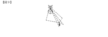
In the CDMA system, in order to realize efficient communication even under a multipath environment (under a frequency selective fading environment) as shown in FIG. 9, a delay time difference as shown in FIG. RAKE combining reception is performed to combine signals (paths) having a time shift as shown in FIG.
[0003]
FIG. 12 shows a configuration example of a conventional CDMA receiver used in a base station or a portable terminal. As shown in FIG. 1, the conventional CDMA receiving apparatus includes a radio receiving unit 101, a
[0004]
The wireless receiving unit 101 performs frequency conversion and AD conversion on a received signal. The
[0005]
Here, it is desirable that the RAKE combining circuit 103 that performs RAKE combining be capable of combining as many paths as possible in order to increase received power and improve communication quality. However, in reality, the number of paths that can be combined is limited due to the limitation of the circuit scale. For this reason, conventionally, some of the paths to be synthesized by the RAKE synthesis circuit 103 are generally selected from the paths existing within the path measurement range by using any one of the following methods A to C. I have.
[0006]
A. A predetermined number of paths are selected in descending order of level (for example, the related art in Japanese Patent Application Laid-Open No. 2000-101549).
[0007]
B. A threshold is determined based on the average power value of the delay profile and the like, and a path having a level higher than the threshold is selected (for example, JP-A-2000-101549).
[0008]
C. It is determined in order from a path existing near a main wave (for example, a path that first arrives at a receiver) whether or not the level is equal to or higher than a threshold, and a predetermined number of paths having the threshold or higher are selected (for example, 2001-186056).
[0009]
[Problems to be solved by the invention]
According to the above-described methods A to C, a path with a high level is selected, so that the received power can be made high and the communication quality can be made high. However, among the methods A to C, in the methods A and B, the paths to be synthesized are selected by paying attention only to the path levels, so that the delay time difference is large among the selected paths. May contain a combination of paths. The maximum value of the delay time difference is a time corresponding to the path measurement range of the
[0010]
As described above, when the paths to be combined are selected by the conventional methods A to C, combinations of paths in which the delay time difference is equal to the path measurement range of the
[0011]
Therefore, an object of the present invention is to provide a CDMA receiving apparatus that can maintain communication quality and reduce the circuit size of a RAKE combining circuit.
[0012]
[Means for Solving the Problems]
In order to achieve the above object, the CDMA receiving apparatus of the present invention selects a path having a smaller level among paths at both ends (a path having the largest delay time difference) existing within a path measurement range of a searcher circuit from selection targets. The process of exclusion is repeatedly performed until the existing range of the path that is not excluded remains within the synthesis range (smaller than the path measurement range) of the RAKE synthesis circuit. Then, the path determined to exist within the synthesis range is set as a synthesis target path in the RAKE configuration circuit. According to this configuration, a continuous path among paths existing within the path measurement range of the searcher circuit is selected as a synthesis target path in the RAKE synthesis circuit, so that the delay time difference of the synthesis target path is compared with the conventional technology. It can be made smaller. As a result, the circuit scale of the RAKE combining circuit can be made smaller than before. In addition, since the higher level is left among the paths at both ends, the received power can be increased and the communication quality can be maintained.
[0013]
More specifically, the CDMA receiver of the present invention
Measuring means for measuring a delay profile on radio wave propagation,
On the basis of the measurement result of the measuring means, the process of excluding the lower-level path among the paths at both ends existing in the path measurement range from the selection target is performed according to the existence range of the path remaining as the selection target. A searcher circuit that includes a path selection circuit that repeats until the value falls within the range.
[0014]
Further, the CDMA receiving apparatus of the present invention reduces the influence of noise.
The path selection circuit is
When the levels of the paths at both ends are the same, the delay time difference between the adjacent inner paths is determined for each of the paths at both ends, and the path having the larger delay time difference among the paths at both ends is excluded from selection targets. are doing.
[0015]
FIGS. 14A, 14B, and 14C show propagation models in a countryside, a hill, and a city, respectively. As can be seen from FIGS. 7A to 7C, the paths are concentrated, and if there is a path having a large delay time difference from the adjacent path, it may be noise. high. Therefore, the influence of noise can be reduced by excluding a path having a large delay time difference from selection targets.
[0016]
In addition, the present invention reduces the processing time of the searcher circuit,
Targeting paths whose level within the path measurement range is equal to or higher than the threshold, and excluding the path with the lower level among the paths at both ends from the selection target, the existence range of the path remaining as the selection target is The process is repeated until the range is smaller than the path measurement range and is within the synthesis range of the RAKE synthesis circuit.
[0017]
According to this configuration, only the paths whose levels are equal to or higher than the threshold are to be processed, so that the processing time of the searcher circuit can be reduced.
[0018]
BEST MODE FOR CARRYING OUT THE INVENTION
Next, embodiments of the present invention will be described in detail with reference to the drawings.
[0019]
FIG. 1 is a block diagram of an embodiment of a CDMA receiver according to the present invention. As shown in FIG. 1, the CDMA receiving apparatus according to the present embodiment includes a
[0020]
The
[0021]
The
[0022]
The delay
[0023]
The
[0024]
The
[0025]
The range determining means 231 has the following functions.
[0026]
A function of copying the contents of the delay
When the copying of the contents of the delay
When the
When it is notified that the path information has been deleted from the
A function of outputting a timing information creation instruction to the timing information creation means 233 when it is determined that the existing range of the path that remains without being discarded is within the synthesis range.
[0027]
The
[0028]
A function of comparing the levels of two paths indicated by the information included in the comparison instruction based on the contents of the path
A function of notifying the
When the levels of the two paths are not the same, a function of deleting the path information relating to the path having the lower level from the path
[0029]
The delay time difference comparing means 235 has the following functions.
[0030]
A function of, when a comparison instruction is sent from the
A function of notifying the range determining means 231 of the same delay time difference between the path at both ends and the inner path, when the difference is the same.
If the delay time difference between the path at both ends and the inner path is not the same, the path information relating to the path having the larger delay time difference among the paths at both ends is deleted from the path
[0031]
The timing
[0032]
Returning to FIG. 1 again, the
[0033]
The signal decoding circuit 4 has a function of performing error correction decoding and the like on the data sequence output from the
[0034]
The recording medium K1 is a semiconductor memory, a disk, or another recording medium, in which a program for causing the DSP to function as the
[0035]
[Operation of the embodiment]
Next, the operation of the present embodiment will be described in detail.
[0036]
The delay
[0037]
Accordingly, the
[0038]
Now, for example, it is assumed that the path information of each of the paths P1 to P5 shown in FIG. 4A is stored in the path
[0039]
Accordingly, the
[0040]
Accordingly, the
[0041]
Accordingly, the timing
[0042]
In the example illustrated in FIG. 4, the determination result of step S <b> 34 did not become YES, but, for example, in S <b> 31, the level of each of the paths P <b> 11 to P <b> 16 illustrated in FIG. If the path information has been stored in the path
[0043]
In the case of the example of FIG. 5, the existence ranges of the paths P11 to P16 do not fall within the synthesis range, and the levels of the paths P11 and P16 at both ends are the same, so the determination results in steps S32 and S34 are NO and YES, respectively. If the decision result in the step S34 is YES, the
[0044]
As a result, the
[0045]
Upon receiving the comparison instruction, the delay time difference comparing means 235 obtains the delay time difference between the paths P11 and P12 and the delay time difference between the paths P15 and P16, and compares the two (S37). In the case of this example, since the delay time difference between the paths P15 and P16 is larger, the delay time difference comparing unit 235 discards the path information of the path P16 stored in the path
[0046]
Upon receiving the notification, the
[0047]
In the examples of FIGS. 4 and 5, although the determination result of step S38 is not YES, for example, in step S31, the paths P21 to P26 shown in FIG. If the path information of the adjacent paths P22 and P25 is stored in the path
[0048]
In the example of FIG. 6, the existence range of the paths P21 to P26 does not fall within the synthesis range, and the levels of the paths P21 and P26 at both ends are equal. Therefore, the determination results in steps S32 and S34 are NO and YES, respectively. If the decision result in the step S34 is YES, the
[0049]
Upon receiving this notification, the
[0050]
Upon receiving this notification, the
[0051]
Upon receiving this notification, the range determination means 231 determines whether or not the next inner path (second inner path) P23, P24 crosses (S43). Here, the cross means that the n-th inner path for the left end path is closer to the right end path than the n-th inner path for the right end path. In the case of this example, since the second inner paths P23 and P24 do not cross, the determination result in step S43 is NO. Then, if the decision result in the step S43 is NO, the range determining means 231 compares the delay time difference between the second inner paths P23, P24 of the paths P21, P26 at both ends to the delay time difference comparing means 235. To do so.
[0052]
Thereby, the delay time difference comparing means 235 obtains the delay time difference between the paths P21 and P23 and the delay time difference between the paths P24 and P26, and compares them (S37). In the example of FIG. 6, since the delay time difference between the paths P24 and P26 is larger, the delay time difference comparing unit 235 discards the path information of the rightmost path P26 stored in the path information storage unit 232 ( S39), and notifies this to the
[0053]
Upon receiving this notification, the
[0054]
Upon receiving the creation instruction, the timing
[0055]
In the examples of FIGS. 4, 5, and 6, the determination result of step S43 is not YES, but in step S31, the path information of each of the paths P30, P31 to P38 shown in FIG. , The determination result in S43 is YES. The paths P31 to P38 are paths at the same level and at the same interval, and the path P30 at the left end is a path having a smaller level than the other paths P31 to P38.
[0056]
In the case of the example of FIG. 7, since the existing range of the paths P30 to P38 does not fall within the synthesis range, the levels of the paths P30 and P38 at both ends are compared (NO in S32, S33). Since the level of the path P30 is lower, the path P30 is excluded from the selection targets (NO in S34, S35).
[0057]
Even if the path P30 is excluded from the selection targets, the levels of the paths P31 and P38 at both ends are compared because the existing range of the paths P31 to P38 to be selected does not fall within the synthesis range (NO in S32, S33). ). Since the levels of the paths P31 and P38 are equal (S34 is YES), the delay time difference between the first inner paths P32 and P37 of the both ends of the paths P31 and P38 is compared (S37). Since the delay time differences are equal (S38: YES), the levels of the first inner paths P32 and P37 are compared (S40). Since the levels of the first inner paths P32 and P37 are equal (S41: YES), it is checked whether or not the next inner paths (second inner paths) P33 and P36 cross (S43).
[0058]
Since the second inner paths P33 and P36 do not cross (S43: NO), the comparison of the delay time difference (S37) and the level comparison (S40) are performed on the second inner paths P33 and P36. .
[0059]
Thereafter, the comparison of the delay time difference (S37) and the comparison of the levels (S40) are performed on the third inner paths P34 and P35.
[0060]
Thereafter, in step S43, it is determined that the fourth inner paths P35 and P34 cross. When the determination result of step S43 is NO, the
[0061]
Accordingly, the timing
[0062]
In the above-described embodiment, when the paths at both ends have the same level, the path to be discarded is determined based on the delay time difference from the inner path and the level of the inner path. The specified path may be discarded. Further, in the above-described embodiment, when the delay time difference from the inner path is the same, the path to be discarded is determined based on the level of the inner path. The path may be discarded. In the above-described embodiment, the case where the present invention is applied to a CDMA receiving apparatus has been described. However, the present invention can also be applied to a base station or a mobile terminal.
[0063]
[Other embodiments]
Next, another embodiment of the present invention will be described.
[0064]
FIG. 8 is a block diagram of another embodiment of the present invention. The difference from the embodiment shown in FIG. 1 is that a
[0065]
The delay profile measurement unit 21a has a function of measuring a delay profile indicating a delay time and a level of each path existing within the path measurement range, and outputting a measurement result to the threshold selection processing unit 24.
[0066]
The threshold selection processing unit 24 selects a path whose level is equal to or greater than the threshold based on the measurement result of the delay profile measurement unit 21a, and stores the delay time and level of the selected path in the delay
[0067]
The recording medium K2 is a semiconductor memory, a disk, or another recording medium, in which a program for causing the DSP to function as the
[0068]
Next, the operation of this embodiment will be described.
[0069]
The delay profile measurement unit 21a measures a delay profile indicating a delay time and a level of each path existing within the path measurement range, and outputs a measurement result to the threshold selection processing unit 24.
[0070]
The threshold selection processing unit 24 selects a path whose level is equal to or larger than the threshold based on the measurement result of the delay profile measurement unit 21a, and stores the delay time and the level of the selected path in the delay
[0071]
Thus, the
[0072]
According to the present embodiment, the paths to be processed by the
[0073]
【The invention's effect】
The first effect is that the circuit size of the RAKE combining circuit can be reduced while maintaining communication quality.
[0074]
The reason is that the process of excluding the path with the smaller level from the paths at both ends (the path with the largest delay time difference) existing within the path measurement range of the searcher circuit remains without being excluded. This is because the repetition is performed until the existing range of the path is within the synthesis range. In other words, only the paths that are determined to be within the synthesis range narrower than the path measurement range are set as synthesis target paths in the RAKE synthesis circuit, and the maximum delay time difference between the synthesis target paths can be reduced. The circuit scale of the RAKE combining circuit can be reduced. In addition, since the higher level is left among the paths at both ends, the received power can be increased and the communication quality can be maintained.
[0075]
The second effect is that the influence of noise can be reduced.
[0076]
The reason for this is that if the paths at both ends have the same level, the path with the larger delay time difference from the inner path is discarded.
[0077]
A third effect is that the processing time of the searcher circuit can be reduced.
[0078]
The reason is that only the paths whose levels are equal to or higher than the threshold are to be processed.
[Brief description of the drawings]
FIG. 1 is a block diagram of one embodiment of the present invention.
FIG. 2 is a block diagram illustrating a configuration example of a
FIG. 3 is a flowchart illustrating a processing example of a
FIG. 4 is a diagram for explaining the operation of the embodiment.
FIG. 5 is a diagram for explaining the operation of the embodiment.
FIG. 6 is a diagram for explaining the operation of the embodiment.
FIG. 7 is a diagram for explaining the operation of the embodiment.
FIG. 8 is a block diagram of another embodiment of the present invention.
FIG. 9 is a diagram showing a partipath propagation environment.
FIG. 10 is a diagram illustrating an example of a received signal.
FIG. 11 is a diagram for explaining RAKE combining.
FIG. 12 is a diagram illustrating a configuration example of a conventional CDMA receiver.
FIG. 13 is a diagram for explaining a problem of the conventional technique.
FIG. 14 is a diagram showing a propagation model in a countryside, a hill, and a city.
[Explanation of symbols]
1, 101 ... wireless receiving unit
2, 2a, 102 ... searcher circuit
21, 21a... Delay profile measuring section
22: delay profile storage unit
23… Path selection circuit
24: threshold selection processing unit
231 ... range determination means
232: Path information storage unit
233 timing information creation means
234: Level comparison means
235 ... Delay time difference comparison means
3,103 ... RAKE synthesis circuit
4,104 ... signal decoding circuit
K1, K2: recording medium
Claims (39)
前記サーチャー回路が、
パス測定範囲内に存在する両端のパスの内のレベルが低い方のパスを選択対象から外すという処理を、選択対象として残ったパスの存在範囲が前記パス測定範囲よりも狭い、前記RAKE合成回路における合成範囲内となるまで繰り返し行うことを特徴とするCDMA受信装置。In a CDMA receiver including a searcher circuit for selecting a path to be demodulated from a delay profile on radio wave propagation, and a RAKE combining circuit for combining the path selected by the searcher circuit,
The searcher circuit is
The RAKE combining circuit, wherein the process of excluding a path having a lower level among the paths at both ends existing in the path measurement range from the selection target is performed, wherein the existence range of the path remaining as the selection target is narrower than the path measurement range. A CDMA receiving apparatus, wherein the processing is repeatedly performed until the sum falls within the synthesis range.
前記サーチャー回路が、
電波伝播上の遅延プロファイルを測定する測定手段と、
該測定手段の測定結果に基づいて、パス測定範囲内に存在する両端のパスの内のレベルが低い方のパスを選択対象から外すという処理を、選択対象として残ったパスの存在範囲が前記合成範囲内となるまで繰り返し行うパス選定回路とを備えたことを特徴とするCDMA受信装置。In the CDMA receiver according to claim 1,
The searcher circuit is
Measuring means for measuring a delay profile on radio wave propagation,
On the basis of the measurement result of the measuring means, the process of excluding the lower-level path among the paths at both ends existing in the path measurement range from the selection target is performed according to the existence range of the path remaining as the selection target. A CDMA receiving apparatus comprising: a path selection circuit that repeats the processing until the signal falls within the range.
前記パス選定回路が、
前記両端のパスのレベルが同じ場合は、前記両端のパスそれぞれについて、隣接する内側パスとの遅延時間差を求め、両端のパスの内の遅延時間差が大きい方のパスを選択対象から外す構成を有することを特徴とするCDMA受信装置。The CDMA receiver according to claim 2,
The path selection circuit is
When the levels of the paths at both ends are the same, the delay time difference between adjacent inner paths is obtained for each of the paths at both ends, and the path having the larger delay time difference among the paths at both ends is excluded from selection targets. A CDMA receiving apparatus characterized by the above-mentioned.
前記パス選定回路が、
前記両端のパスの、隣接する内側パスとの遅延時間差が等しい場合は、前記両端のパスの内の、隣接する内側パスのレベルが低い方を選択対象から外す構成を有することを特徴とするCDMA受信装置。The CDMA receiver according to claim 3,
The path selection circuit is
When the delay time difference between the paths at both ends and the adjacent inner path is equal, a configuration is adopted in which, of the paths at both ends, the lower level of the adjacent inner path is excluded from selection targets. Receiver.
前記パス選定回路が、前記両端のパスのレベルが同じ場合は、下記A〜Gの処理を行う構成を有することを特徴とするCDMA受信装置。
A.両端のパスそれぞれについて、未処理の内側パスの内の、最も両端のパスに近い内側パスとの遅延時間差を求め、両者を比較する。
B.Aにおいて、両者が同一でないと判定した場合は、両端のパスの内の、遅延時間差が大きな方のパスを選択対象から外す。
C.Aにおいて、両者が同一であると判定した場合は、未処理の内側パスの内の、最も両端のパスに近い内側パスのレベルを比較する。
D.Cにおいて、両者が同一でないと判定した場合は、両端のパスの内の、内側パスのレベルが低い方のパスを選択対象から外す。
E.Cにおいて、両者が同一であると判定した場合は、次の内側パスがクロスするか否かを調べる。
F.Eにおいて、クロスしないと判定した場合は、次の内側パスを処理対象にしてAの処理を行う。
G.Eにおいて、クロスすると判定した場合は、選択対象として残っているパスの中から、合成範囲内に存在することになるパスを選択する。In the CDMA receiver according to claim 2,
A CDMA receiving apparatus, wherein the path selection circuit has a configuration for performing the following processes A to G when the levels of the paths at both ends are the same.
A. For each of the paths at both ends, the delay time difference between the unprocessed inner path and the inner path closest to the both ends is calculated, and the two are compared.
B. In A, when it is determined that the two are not the same, the path having the larger delay time difference among the paths at both ends is excluded from selection targets.
C. In A, when it is determined that the two are the same, the level of the inner path closest to the end path among the unprocessed inner paths is compared.
D. If it is determined in C that the two are not the same, the path having the lower level of the inner path among the paths at both ends is excluded from selection targets.
E. FIG. If it is determined in C that they are the same, it is checked whether or not the next inner path crosses.
F. In E, if it is determined that no crossing occurs, the process of A is performed on the next inner path as a processing target.
G. FIG. In E, if it is determined to cross, a path that will be within the synthesis range is selected from the paths remaining as selection targets.
前記パス選定回路が、
パス測定範囲内に存在する両端のパスの内のレベルが低い方のパスを選択対象から外すレベル比較手段と、
選択対象として残ったパスの存在する範囲が、前記合成範囲内であるか否かを調べ、合成範囲内である場合は、前記残ったパスを前記RAKE合成回路の合成対象パスとし、合成範囲内でない場合は、前記レベル比較手段を動作させる範囲判定手段を備えたことを特徴とするCDMA受信装置。In the CDMA receiver according to claim 2,
The path selection circuit is
A level comparing means for excluding a path having a lower level among paths at both ends existing in the path measurement range from selection targets,
It is checked whether or not the range in which the path remaining as the selection target exists is within the synthesis range. If the range is within the synthesis range, the remaining path is set as the synthesis target path of the RAKE synthesis circuit. If not, a CDMA receiving apparatus comprising a range determining means for operating the level comparing means.
前記両端のパスのレベルが等しい場合、前記両端のパスそれぞれについて、隣接する内側パスとの遅延時間差を求め、遅延時間差の大きい方のパスを選択対象から外す遅延時間差比較手段を備えたことを特徴とするCDMA受信装置。In the CDMA receiver according to claim 6,
When the levels of the paths at both ends are equal, a delay time difference comparing means for obtaining a delay time difference from an adjacent inner path for each of the paths at both ends and excluding a path having a larger delay time difference from selection targets is provided. CDMA receiver.
前記レベル比較手段が、
前記両端のパスの、隣接する内側パスとの遅延時間差が同一である場合、前記内側パスのレベルを比較し、前記両端のパスの内の、内側パスのレベルが低い方のパスを選択対象から外す構成を有することを特徴とするCDMA受信装置。In the CDMA receiver according to claim 7,
The level comparing means includes:
In the case where the delay time difference between the both ends of the path and the adjacent inner path is the same, the level of the inner path is compared, and among the paths at both ends, the path having the lower level of the inner path is selected from the selection targets. A CDMA receiver having a configuration for removing the CDMA receiver.
前記サーチャー回路が、
前記パス測定範囲内に存在するレベルが閾値以上のパスを対象にし、両端のパスの内のレベルが低い方のパスを選択対象から外すという処理を、選択対象として残ったパスの存在範囲が前記パス測定範囲よりも狭い、前記RAKE合成回路における合成範囲内となるまで繰り返し行うことを特徴とするCDMA受信装置。The CDMA receiver according to claim 1,
The searcher circuit is
Targeting paths whose level within the path measurement range is equal to or higher than the threshold, and excluding the path with the lower level among the paths at both ends from the selection target, the existence range of the path remaining as the selection target is A CDMA receiving apparatus, wherein the CDMA receiving apparatus repeats the processing until it is within a synthesis range of the RAKE synthesis circuit, which is narrower than a path measurement range.
前記サーチャー回路が、
電波伝播上の遅延プロファイルを測定する測定手段と、
該測定手段の測定結果に基づいて、パス測定範囲に存在するレベルが閾値以上のパスを選定する閾値選定処理手段と、
該閾値選定処理手段で選定されたパスを対象にし、両端のパスの内のレベルが低い方のパスを選択対象から外すという処理を、選択対象として残ったパスの存在範囲が前記合成範囲内となるまで繰り返し行うパス選定回路とを備えたことを特徴とするCDMA受信装置。In the CDMA receiver according to claim 9,
The searcher circuit is
Measuring means for measuring a delay profile on radio wave propagation,
Threshold selection processing means for selecting a path whose level in the path measurement range is equal to or greater than a threshold based on the measurement result of the measurement means,
Targeting the path selected by the threshold selection processing means, the processing of excluding the path with the lower level among the paths at both ends from the selection target, the existence range of the path remaining as the selection target is determined to be within the synthesis range. A CDMA receiving apparatus comprising: a path selection circuit that repeats a path selection until the CDMA receiving apparatus performs the processing.
前記パス選定回路が、
前記両端のパスのレベルが同じ場合は、前記両端のパスそれぞれについて、隣接する内側パスとの遅延時間差を求め、両端のパスの内の遅延時間差が大きい方のパスを選択対象から外す構成を有することを特徴とするCDMA受信装置。The CDMA receiver according to claim 10,
The path selection circuit is
When the levels of the paths at both ends are the same, the delay time difference between adjacent inner paths is obtained for each of the paths at both ends, and the path having the larger delay time difference among the paths at both ends is excluded from selection targets. A CDMA receiving apparatus characterized by the above-mentioned.
前記パス選定回路が、
前記両端のパスの、隣接する内側パスとの遅延時間差が等しい場合は、前記両端のパスの内の、隣接する内側パスのレベルが低い方を選択対象から外す構成を有することを特徴とするCDMA受信装置。The CDMA receiver according to claim 11,
The path selection circuit is
When the delay time difference between the paths at both ends and the adjacent inner path is equal, a configuration is adopted in which, of the paths at both ends, the lower level of the adjacent inner path is excluded from selection targets. Receiver.
前記サーチャー回路が、
パス測定範囲内に存在する両端のパスの内のレベルが低い方のパスを選択対象から外すという処理を、選択対象として残ったパスの存在範囲が前記パス測定範囲よりも狭い、前記RAKE合成回路における合成範囲内となるまで繰り返し行うことを特徴とする基地局。In a base station including a searcher circuit for selecting a path to be demodulated from a delay profile on radio wave propagation, and a RAKE combining circuit for combining the path selected by the searcher circuit,
The searcher circuit is
The RAKE combining circuit, wherein the process of excluding a path having a lower level among the paths at both ends existing in the path measurement range from the selection target is performed, wherein the existence range of the path remaining as the selection target is narrower than the path measurement range. A base station, wherein the repetition is performed until the sum falls within the combining range.
前記サーチャー回路が、
電波伝播上の遅延プロファイルを測定する測定手段と、
該測定手段の測定結果に基づいて、パス測定範囲内に存在する両端のパスの内のレベルが低い方のパスを選択対象から外すという処理を、選択対象として残ったパスの存在範囲が前記合成範囲内となるまで繰り返し行うパス選定回路とを備えたことを特徴とする基地局。In the base station according to claim 13,
The searcher circuit is
Measuring means for measuring a delay profile on radio wave propagation,
On the basis of the measurement result of the measuring means, the process of excluding the lower-level path among the paths at both ends existing in the path measurement range from the selection target is performed according to the existence range of the path remaining as the selection target. A base station comprising: a path selection circuit that repeats the operation until the path is within the range.
前記パス選定回路が、
前記両端のパスのレベルが同じ場合は、前記両端のパスそれぞれについて、隣接する内側パスとの遅延時間差を求め、両端のパスの内の遅延時間差が大きい方のパスを選択対象から外す構成を有することを特徴とする基地局。In the base station according to claim 14,
The path selection circuit is
When the levels of the paths at both ends are the same, the delay time difference between adjacent inner paths is obtained for each of the paths at both ends, and the path having the larger delay time difference among the paths at both ends is excluded from selection targets. A base station, characterized in that:
前記パス選定回路が、
前記両端のパスの、隣接する内側パスとの遅延時間差が等しい場合は、前記両端のパスの内の、隣接する内側パスのレベルが低い方を選択対象から外す構成を有することを特徴とする基地局。In the base station according to claim 15,
The path selection circuit is
A base having a configuration in which, when the delay time difference between the paths at the both ends and the adjacent inner path is equal, the lower level of the adjacent inner path among the paths at the both ends is excluded from selection targets; Bureau.
前記サーチャー回路が、
前記パス測定範囲内に存在するレベルが閾値以上のパスを対象にし、両端のパスの内のレベルが低い方のパスを選択対象から外すという処理を、選択対象として残ったパスの存在範囲が前記パス測定範囲よりも狭い、前記RAKE合成回路における合成範囲内となるまで繰り返し行うことを特徴とする基地局。In the base station according to claim 13,
The searcher circuit is
Targeting paths whose level within the path measurement range is equal to or higher than the threshold, and excluding the path with the lower level among the paths at both ends from the selection target, the existence range of the path remaining as the selection target is A base station, wherein the repetition is performed until the range becomes smaller than a path measurement range and is within a synthesis range of the RAKE synthesis circuit.
前記サーチャー回路が、
電波伝播上の遅延プロファイルを測定する測定手段と、
該測定手段の測定結果に基づいて、パス測定範囲に存在するレベルが閾値以上のパスを選定する閾値選定処理手段と、
該閾値選定処理手段で選定されたパスを対象にし、両端のパスの内のレベルが低い方のパスを選択対象から外すという処理を、選択対象として残ったパスの存在範囲が前記合成範囲内となるまで繰り返し行うパス選定回路とを備えたことを特徴とする基地局。In the base station according to claim 17,
The searcher circuit is
Measuring means for measuring a delay profile on radio wave propagation,
Threshold selection processing means for selecting a path whose level in the path measurement range is equal to or greater than a threshold based on the measurement result of the measurement means,
Targeting the path selected by the threshold selection processing means, the processing of excluding the path with the lower level among the paths at both ends from the selection target, the existence range of the path remaining as the selection target is determined to be within the synthesis range. A base station, comprising: a path selection circuit that repeats the path selection until the base station has a path.
前記パス選定回路が、
前記両端のパスのレベルが同じ場合は、前記両端のパスそれぞれについて、隣接する内側パスとの遅延時間差を求め、両端のパスの内の遅延時間差が大きい方のパスを選択対象から外す構成を有することを特徴とする基地局。In the base station according to claim 18,
The path selection circuit is
When the levels of the paths at both ends are the same, the delay time difference between adjacent inner paths is obtained for each of the paths at both ends, and the path having the larger delay time difference among the paths at both ends is excluded from selection targets. A base station, characterized in that:
前記パス選定回路が、
前記両端のパスの、隣接する内側パスとの遅延時間差が等しい場合は、前記両端のパスの内の、隣接する内側パスのレベルが低い方を選択対象から外す構成を有することを特徴とする基地局。In the base station according to claim 19,
The path selection circuit is
A base having a configuration in which, when the delay time difference between the paths at the both ends and the adjacent inner path is equal, the lower level of the adjacent inner path among the paths at the both ends is excluded from selection targets; Bureau.
前記サーチャー回路が、
パス測定範囲内に存在する両端のパスの内のレベルが低い方のパスを選択対象から外すという処理を、選択対象として残ったパスの存在範囲が前記パス測定範囲よりも狭い、前記RAKE合成回路における合成範囲内となるまで繰り返し行うことを特徴とする携帯端末。In a portable terminal including a searcher circuit for selecting a path to be demodulated from a delay profile on radio wave propagation, and a RAKE combining circuit for combining the path selected by the searcher circuit,
The searcher circuit is
The RAKE combining circuit, wherein the process of excluding a path having a lower level among the paths at both ends existing in the path measurement range from the selection target is performed, wherein the existence range of the path remaining as the selection target is narrower than the path measurement range. A portable terminal characterized in that the process is repeatedly performed until the result falls within the synthesis range.
前記サーチャー回路が、
電波伝播上の遅延プロファイルを測定する測定手段と、
該測定手段の測定結果に基づいて、パス測定範囲内に存在する両端のパスの内のレベルが低い方のパスを選択対象から外すという処理を、選択対象として残ったパスの存在範囲が前記合成範囲内となるまで繰り返し行うパス選定回路とを備えたことを特徴とする携帯端末。The mobile terminal according to claim 21,
The searcher circuit is
Measuring means for measuring a delay profile on radio wave propagation,
On the basis of the measurement result of the measuring means, the process of excluding the lower-level path among the paths at both ends existing in the path measurement range from the selection target is performed according to the existence range of the path remaining as the selection target. A portable terminal, comprising: a path selection circuit that repeats the process until the value falls within the range.
前記パス選定回路が、
前記両端のパスのレベルが同じ場合は、前記両端のパスそれぞれについて、隣接する内側パスとの遅延時間差を求め、両端のパスの内の遅延時間差が大きい方のパスを選択対象から外す構成を有することを特徴とする携帯端末。The mobile terminal according to claim 22,
The path selection circuit is
When the levels of the paths at both ends are the same, the delay time difference between adjacent inner paths is obtained for each of the paths at both ends, and the path having the larger delay time difference among the paths at both ends is excluded from selection targets. A mobile terminal, characterized in that:
前記パス選定回路が、
前記両端のパスの、隣接する内側パスとの遅延時間差が等しい場合は、前記両端のパスの内の、隣接する内側パスのレベルが低い方を選択対象から外す構成を有することを特徴とする携帯端末。The mobile terminal according to claim 23,
The path selection circuit is
When the delay time difference between the paths at both ends and the adjacent inner paths is equal, a configuration is adopted in which, of the paths at both ends, the lower level of the adjacent inner path is excluded from selection targets. Terminal.
前記サーチャー回路が、
前記パス測定範囲内に存在するレベルが閾値以上のパスを対象にし、両端のパスの内のレベルが低い方のパスを選択対象から外すという処理を、選択対象として残ったパスの存在範囲が前記パス測定範囲よりも狭い、前記RAKE合成回路における合成範囲内となるまで繰り返し行うことを特徴とする携帯端末。The mobile terminal according to claim 21,
The searcher circuit is
Targeting paths whose level within the path measurement range is equal to or higher than the threshold, and excluding the path with the lower level among the paths at both ends from the selection target, the existence range of the path remaining as the selection target is A portable terminal, wherein the repetition is performed until the range is smaller than a path measurement range and is within a synthesis range of the RAKE synthesis circuit.
前記サーチャー回路が、
電波伝播上の遅延プロファイルを測定する測定手段と、
該測定手段の測定結果に基づいて、パス測定範囲に存在するレベルが閾値以上のパスを選定する閾値選定処理手段と、
該閾値選定処理手段で選定されたパスを対象にし、両端のパスの内のレベルが低い方のパスを選択対象から外すという処理を、選択対象として残ったパスの存在範囲が前記合成範囲内となるまで繰り返し行うパス選定回路とを備えたことを特徴とする携帯端末。The mobile terminal according to claim 25,
The searcher circuit is
Measuring means for measuring a delay profile on radio wave propagation,
Threshold selection processing means for selecting a path whose level in the path measurement range is equal to or greater than a threshold based on the measurement result of the measurement means,
Targeting the path selected by the threshold selection processing means, the processing of excluding the path with the lower level among the paths at both ends from the selection target, the existence range of the path remaining as the selection target is determined to be within the synthesis range. A mobile terminal, comprising: a path selection circuit that repeats a path selection until the mobile terminal has a path selection circuit.
前記パス選定回路が、
前記両端のパスのレベルが同じ場合は、前記両端のパスそれぞれについて、隣接する内側パスとの遅延時間差を求め、両端のパスの内の遅延時間差が大きい方のパスを選択対象から外す構成を有することを特徴とする携帯端末。The mobile terminal according to claim 26,
The path selection circuit is
When the levels of the paths at both ends are the same, the delay time difference between adjacent inner paths is obtained for each of the paths at both ends, and the path having the larger delay time difference among the paths at both ends is excluded from selection targets. A mobile terminal, characterized in that:
前記パス選定回路が、
前記両端のパスの、隣接する内側パスとの遅延時間差が等しい場合は、前記両端のパスの内の、隣接する内側パスのレベルが低い方を選択対象から外す構成を有することを特徴とする携帯端末。The mobile terminal according to claim 27,
The path selection circuit is
When the delay time difference between the paths at both ends and the adjacent inner paths is equal, a configuration is adopted in which, of the paths at both ends, the lower level of the adjacent inner path is excluded from selection targets. Terminal.
パス測定範囲内に存在する両端のパスの内のレベルが低い方のパスを選択対象から外すという処理を、選択対象として残ったパスの存在範囲が前記パス測定範囲よりも狭い、前記RAKE合成回路における合成範囲内となるまで繰り返し行うことを特徴とするパス選定方法。In a path selection method for selecting a demodulation target path to be combined by a RAKE combining circuit from a delay profile on radio wave propagation,
The RAKE combining circuit, wherein the process of excluding a path having a lower level among the paths at both ends existing in the path measurement range from the selection target is performed, wherein the existence range of the path remaining as the selection target is narrower than the path measurement range. A path selection method characterized in that the method is repeatedly performed until the result falls within the synthesis range.
電波伝播上の遅延プロファイルを測定する測定ステップと、
該測定ステップの測定結果に基づいて、パス測定範囲内に存在する両端のパスの内のレベルが低い方のパスを選択対象から外すという処理を、選択対象として残ったパスの存在範囲が前記合成範囲内となるまで繰り返し行うパス選定ステップとを含むことを特徴とするパス選定方法。In the path selecting method according to claim 29,
A measuring step of measuring a delay profile on radio wave propagation;
Based on the measurement result of the measurement step, the process of excluding, from the selection target, the lower-level path of the paths at both ends existing in the path measurement range is performed by combining the existing range of the path remaining as the selection target. A path selection step of repeatedly performing the path selection until it is within the range.
前記パス選定ステップは、
前記両端のパスのレベルが同じ場合は、前記両端のパスそれぞれについて、隣接する内側パスとの遅延時間差を求め、両端のパスの内の遅延時間差が大きい方のパスを選択対象から外すことを特徴とするパス選定方法。31. The path selection method according to claim 30,
The path selection step includes:
When the levels of the paths at both ends are the same, a delay time difference between adjacent inner paths is obtained for each of the paths at both ends, and a path having a larger delay time difference among the paths at both ends is excluded from selection targets. Path selection method.
前記パス選定ステップは、
前記両端のパスの、隣接する内側パスとの遅延時間差が等しい場合は、前記両端のパスの内の、隣接する内側パスのレベルが低い方を選択対象から外すことを特徴とするパス選定方法。The path selection method according to claim 31,
The path selection step includes:
A path selection method, wherein, when the delay time difference between the path at both ends and the adjacent inner path is equal, the lower level of the adjacent inner path among the paths at both ends is excluded from selection targets.
前記パス選定ステップは、前記両端のパスのレベルが同じ場合は、下記A〜Gの処理を行うことを特徴とするパス選定方法。
A.両端のパスそれぞれについて、未処理の内側パスの内の、最も両端のパスに近い内側パスとの遅延時間差を求め、両者を比較する。
B.Aにおいて、両者が同一でないと判定した場合は、両端のパスの内の、遅延時間差が大きな方のパスを選択対象から外す。
C.Aにおいて、両者が同一であると判定した場合は、未処理の内側パスの内の、最も両端のパスに近い内側パスのレベルを比較する。
D.Cにおいて、両者が同一でないと判定した場合は、両端のパスの内の、内側パスのレベルが低い方のパスを選択対象から外す。
E.Cにおいて、両者が同一であると判定した場合は、次の内側パスがクロスするか否かを調べる。
F.Eにおいて、クロスしないと判定した場合は、次の内側パスを処理対象にしてAの処理を行う。
G.Eにおいて、クロスすると判定した場合は、選択対象として残っているパスの中から、合成範囲内に存在することになるパスを選択する。In the path selecting method according to claim 30,
The path selection method is characterized in that, in the path selection step, when the levels of the paths at both ends are the same, the following processes A to G are performed.
A. For each of the paths at both ends, the delay time difference between the unprocessed inner path and the inner path closest to the both ends is calculated, and the two are compared.
B. In A, when it is determined that the two are not the same, the path having the larger delay time difference among the paths at both ends is excluded from selection targets.
C. In A, when it is determined that the two are the same, the level of the inner path closest to the end path among the unprocessed inner paths is compared.
D. If it is determined in C that the two are not the same, the path having the lower level of the inner path among the paths at both ends is excluded from selection targets.
E. FIG. If it is determined in C that they are the same, it is checked whether or not the next inner path crosses.
F. In E, if it is determined that no crossing occurs, the process of A is performed on the next inner path as a processing target.
G. FIG. In E, if it is determined to cross, a path that will be within the synthesis range is selected from the paths remaining as selection targets.
前記パス測定範囲内に存在するレベルが閾値以上のパスを対象にし、両端のパスの内のレベルが低い方のパスを選択対象から外すという処理を、選択対象として残ったパスの存在範囲が前記パス測定範囲よりも狭い、前記RAKE合成回路における合成範囲内となるまで繰り返し行うことを特徴とするパス選定方法。30. The path selection method according to claim 29,
Targeting paths whose level within the path measurement range is equal to or higher than the threshold, and excluding the path with the lower level among the paths at both ends from the selection target, the existence range of the path remaining as the selection target is A path selection method, wherein the method is repeatedly performed until the range is smaller than the path measurement range and is within the synthesis range of the RAKE synthesis circuit.
電波伝播上の遅延プロファイルを測定する測定ステップと、
該測定ステップの測定結果に基づいて、パス測定範囲に存在するレベルが閾値以上のパスを選定する閾値選定処理ステップと、
該閾値選定処理ステップで選定されたパスを対象にして、両端のパスの内のレベルが低い方のパスを選択対象から外すという処理を、選択対象として残ったパスの存在範囲が前記合成範囲内となるまで繰り返し行うパス選定ステップとを含むことを特徴とするパス選定方法。In the path selecting method according to claim 34,
A measuring step of measuring a delay profile on radio wave propagation;
A threshold selection processing step of selecting a path whose level in the path measurement range is equal to or greater than a threshold based on the measurement result of the measurement step;
For the path selected in the threshold value selection processing step, the processing of excluding the path with the lower level among the paths at both ends from the selection target is performed, and the existence range of the path remaining as the selection target is within the synthesis range. A path selection step that is repeatedly performed until the following condition is satisfied.
前記パス選定ステップは、
前記両端のパスのレベルが同じ場合は、前記両端のパスそれぞれについて、隣接する内側パスとの遅延時間差を求め、両端のパスの内の遅延時間差が大きい方のパスを選択対象から外すことを特徴とするパス選定方法。36. The path selection method according to claim 35,
The path selection step includes:
When the levels of the paths at both ends are the same, a delay time difference between adjacent inner paths is obtained for each of the paths at both ends, and a path having a larger delay time difference among the paths at both ends is excluded from selection targets. Path selection method.
前記パス選定ステップは、
前記両端のパスの、隣接する内側パスとの遅延時間差が等しい場合は、前記両端のパスの内の、隣接する内側パスのレベルが低い方を選択対象から外すことを特徴とするパス選定方法。37. The path selection method according to claim 36,
The path selection step includes:
A path selection method, wherein, when the delay time difference between the path at both ends and the adjacent inner path is equal, the lower level of the adjacent inner path among the paths at both ends is excluded from selection targets.
前記コンピュータに、
パス測定範囲内に存在する両端のパスの内のレベルが低い方のパスを選択対象から外すという処理を、選択対象として残ったパスの存在範囲が前記パス測定範囲よりも狭い、前記RAKE合成回路における合成範囲内となるまで繰り返し行わせるプログラム。A program for allowing a computer to select a demodulation target path to be synthesized by a RAKE synthesis circuit from a delay profile on radio wave propagation,
To the computer,
The RAKE combining circuit, wherein the process of excluding a path having a lower level among the paths at both ends existing in the path measurement range from the selection target is performed, wherein the existence range of the path remaining as the selection target is narrower than the path measurement range. Program to be repeatedly executed until within the synthesis range in.
前記コンピュータに、
パス測定範囲内に存在するレベルが閾値以上のパスを対象にし、両端のパスの内のレベルが低い方のパスを選択対象から外すという処理を、選択対象として残ったパスの存在範囲が前記パス測定範囲よりも狭い、前記RAKE合成回路における合成範囲内となるまで繰り返し行わせるプログラム。A program for allowing a computer to select a demodulation target path to be synthesized by a RAKE synthesis circuit from a delay profile on radio wave propagation,
To the computer,
The process of targeting paths whose level within the path measurement range is equal to or higher than the threshold and excluding the path having the lower level among the paths at both ends from the selection target is performed by changing the existence range of the path remaining as the selection target to the path. A program that is repeatedly executed until the value falls within the synthesis range of the RAKE synthesis circuit, which is smaller than the measurement range.
Priority Applications (4)
| Application Number | Priority Date | Filing Date | Title |
|---|---|---|---|
| JP2001321568A JP3565199B2 (en) | 2001-10-19 | 2001-10-19 | CDMA receiver, base station, mobile terminal, path selection method and program |
| US10/235,712 US20030076800A1 (en) | 2001-10-19 | 2002-09-06 | CDMA receiver, and path selection method |
| DE60215753T DE60215753D1 (en) | 2001-10-19 | 2002-09-10 | CDMA receiver and method for route selection |
| EP20020020406 EP1304814B1 (en) | 2001-10-19 | 2002-09-10 | CDMA receiver, and path selection method |
Applications Claiming Priority (1)
| Application Number | Priority Date | Filing Date | Title |
|---|---|---|---|
| JP2001321568A JP3565199B2 (en) | 2001-10-19 | 2001-10-19 | CDMA receiver, base station, mobile terminal, path selection method and program |
Publications (2)
| Publication Number | Publication Date |
|---|---|
| JP2003124847A JP2003124847A (en) | 2003-04-25 |
| JP3565199B2 true JP3565199B2 (en) | 2004-09-15 |
Family
ID=19138761
Family Applications (1)
| Application Number | Title | Priority Date | Filing Date |
|---|---|---|---|
| JP2001321568A Expired - Fee Related JP3565199B2 (en) | 2001-10-19 | 2001-10-19 | CDMA receiver, base station, mobile terminal, path selection method and program |
Country Status (4)
| Country | Link |
|---|---|
| US (1) | US20030076800A1 (en) |
| EP (1) | EP1304814B1 (en) |
| JP (1) | JP3565199B2 (en) |
| DE (1) | DE60215753D1 (en) |
Families Citing this family (2)
| Publication number | Priority date | Publication date | Assignee | Title |
|---|---|---|---|---|
| US7460583B2 (en) * | 2003-12-15 | 2008-12-02 | Telefonaktiebolaget Lm Ericsson (Publ) | Method for path searching and verification |
| CN102868598B (en) * | 2011-07-07 | 2015-07-29 | 株式会社日立制作所 | Control device and control method |
Family Cites Families (7)
| Publication number | Priority date | Publication date | Assignee | Title |
|---|---|---|---|---|
| FR2737362B1 (en) * | 1995-07-25 | 1997-10-10 | Matra Communication | PROCESS FOR SELECTING THE PROPAGATION DELAYS RETAINED TO RECEIVE MESSAGES TRANSMITTED BY RADIOCOMMUNICATION WITH A SPREAD OF SPECTRUM |
| JP2000082973A (en) * | 1998-09-04 | 2000-03-21 | Fujitsu Ltd | Path search device and cdma receiver using the same |
| JP3031351B2 (en) * | 1998-09-24 | 2000-04-10 | 日本電気株式会社 | CDMA receiving apparatus, path detecting method used therefor, and recording medium recording control program therefor |
| JP3600529B2 (en) * | 1999-03-01 | 2004-12-15 | 富士通株式会社 | CDMA receiver |
| JP2001186056A (en) * | 1999-12-27 | 2001-07-06 | Toshiba Corp | Cdma demodulation method and cdma demodulator |
| JP2001211101A (en) * | 2000-01-26 | 2001-08-03 | Nec Corp | Cdma receiver with low power consumption and its power consumption reducing method |
| JP3440919B2 (en) * | 2000-04-07 | 2003-08-25 | 日本電気株式会社 | Multipath detection circuit |
-
2001
- 2001-10-19 JP JP2001321568A patent/JP3565199B2/en not_active Expired - Fee Related
-
2002
- 2002-09-06 US US10/235,712 patent/US20030076800A1/en not_active Abandoned
- 2002-09-10 EP EP20020020406 patent/EP1304814B1/en not_active Expired - Fee Related
- 2002-09-10 DE DE60215753T patent/DE60215753D1/en not_active Expired - Lifetime
Also Published As
| Publication number | Publication date |
|---|---|
| JP2003124847A (en) | 2003-04-25 |
| US20030076800A1 (en) | 2003-04-24 |
| EP1304814A2 (en) | 2003-04-23 |
| EP1304814A3 (en) | 2004-02-11 |
| DE60215753D1 (en) | 2006-12-14 |
| EP1304814B1 (en) | 2006-11-02 |
Similar Documents
| Publication | Publication Date | Title |
|---|---|---|
| JP4559002B2 (en) | Apparatus and method for selecting correlation timing in rake receiver | |
| JP2001333002A (en) | Method for estimating transmitting antenna weight in mobile communication system and mobile communication terminal | |
| JP3565199B2 (en) | CDMA receiver, base station, mobile terminal, path selection method and program | |
| JP3482931B2 (en) | Radio communication apparatus and searcher control method for DS / CDMA mobile communication system | |
| JP4815561B2 (en) | Method and apparatus for managing multipath signals | |
| US7359399B2 (en) | CDMA path protection method based on path protection information | |
| JP4165238B2 (en) | Path search circuit, method and program | |
| JP2000165351A (en) | Method and device for controlling searcher and radio communication equipment | |
| JP2001016134A (en) | Receiver for cdma and path searching method therefor | |
| JPH10271034A (en) | Cdma mobile communication receiver | |
| JP3441431B2 (en) | RAKE receiver and receiving method | |
| KR100366292B1 (en) | Symbol data timing alignment and combining method for reducing the number of FIFO registers, and a rake receiver and it's architecture with the proposed combining technique | |
| US7269437B2 (en) | Transmission power control circuit using W-CDMA method | |
| KR20020093389A (en) | Method for Canceling Interference for Parallel Type for CDMA Receiver | |
| JP2009117940A (en) | Wireless diversity reception apparatus and reception method | |
| JP3675446B2 (en) | CDMA receiver, path management method thereof, and path management program | |
| JP2002009663A (en) | Receiver for spread spectrum communication | |
| JP3429716B2 (en) | Demodulation method and apparatus in wireless communication system using M-sequence quadrature modulation | |
| JP2004297533A (en) | Receiver and receiving method | |
| KR100426946B1 (en) | Grouping Interference Cancellation Apparatus using Adaptive Sector Antenna, Adaptive Sector Antennas for Load Distribution, and the Sectorization Methods | |
| JP2001274778A (en) | Error correction signal generator | |
| JP2006148196A (en) | Radio communication system | |
| JP2002118500A (en) | Mobile station for cdma communication system and method for assigning its finger | |
| JP4519622B2 (en) | Path search processing method for mobile radio terminal device | |
| JP5464373B2 (en) | Delay amount determining apparatus, delay amount determining method, multiple signal communication system, and multiple signal communication method |
Legal Events
| Date | Code | Title | Description |
|---|---|---|---|
| A977 | Report on retrieval |
Free format text: JAPANESE INTERMEDIATE CODE: A971007 Effective date: 20040401 |
|
| TRDD | Decision of grant or rejection written | ||
| A01 | Written decision to grant a patent or to grant a registration (utility model) |
Free format text: JAPANESE INTERMEDIATE CODE: A01 Effective date: 20040518 |
|
| A61 | First payment of annual fees (during grant procedure) |
Free format text: JAPANESE INTERMEDIATE CODE: A61 Effective date: 20040531 |
|
| R150 | Certificate of patent or registration of utility model |
Free format text: JAPANESE INTERMEDIATE CODE: R150 |
|
| LAPS | Cancellation because of no payment of annual fees |