EP1143581A2 - Solid-state laser and optical transmitter - Google Patents
Solid-state laser and optical transmitter Download PDFInfo
- Publication number
- EP1143581A2 EP1143581A2 EP00120122A EP00120122A EP1143581A2 EP 1143581 A2 EP1143581 A2 EP 1143581A2 EP 00120122 A EP00120122 A EP 00120122A EP 00120122 A EP00120122 A EP 00120122A EP 1143581 A2 EP1143581 A2 EP 1143581A2
- Authority
- EP
- European Patent Office
- Prior art keywords
- solid
- gain medium
- state
- medium
- opposite
- Prior art date
- Legal status (The legal status is an assumption and is not a legal conclusion. Google has not performed a legal analysis and makes no representation as to the accuracy of the status listed.)
- Withdrawn
Links
Images



Classifications
-
- H—ELECTRICITY
- H01—ELECTRIC ELEMENTS
- H01S—DEVICES USING THE PROCESS OF LIGHT AMPLIFICATION BY STIMULATED EMISSION OF RADIATION [LASER] TO AMPLIFY OR GENERATE LIGHT; DEVICES USING STIMULATED EMISSION OF ELECTROMAGNETIC RADIATION IN WAVE RANGES OTHER THAN OPTICAL
- H01S3/00—Lasers, i.e. devices using stimulated emission of electromagnetic radiation in the infrared, visible or ultraviolet wave range
- H01S3/05—Construction or shape of optical resonators; Accommodation of active medium therein; Shape of active medium
- H01S3/06—Construction or shape of active medium
- H01S3/0602—Crystal lasers or glass lasers
-
- H—ELECTRICITY
- H01—ELECTRIC ELEMENTS
- H01S—DEVICES USING THE PROCESS OF LIGHT AMPLIFICATION BY STIMULATED EMISSION OF RADIATION [LASER] TO AMPLIFY OR GENERATE LIGHT; DEVICES USING STIMULATED EMISSION OF ELECTROMAGNETIC RADIATION IN WAVE RANGES OTHER THAN OPTICAL
- H01S3/00—Lasers, i.e. devices using stimulated emission of electromagnetic radiation in the infrared, visible or ultraviolet wave range
- H01S3/05—Construction or shape of optical resonators; Accommodation of active medium therein; Shape of active medium
- H01S3/08—Construction or shape of optical resonators or components thereof
-
- H—ELECTRICITY
- H01—ELECTRIC ELEMENTS
- H01S—DEVICES USING THE PROCESS OF LIGHT AMPLIFICATION BY STIMULATED EMISSION OF RADIATION [LASER] TO AMPLIFY OR GENERATE LIGHT; DEVICES USING STIMULATED EMISSION OF ELECTROMAGNETIC RADIATION IN WAVE RANGES OTHER THAN OPTICAL
- H01S3/00—Lasers, i.e. devices using stimulated emission of electromagnetic radiation in the infrared, visible or ultraviolet wave range
- H01S3/05—Construction or shape of optical resonators; Accommodation of active medium therein; Shape of active medium
- H01S3/08—Construction or shape of optical resonators or components thereof
- H01S3/08059—Constructional details of the reflector, e.g. shape
-
- H—ELECTRICITY
- H01—ELECTRIC ELEMENTS
- H01S—DEVICES USING THE PROCESS OF LIGHT AMPLIFICATION BY STIMULATED EMISSION OF RADIATION [LASER] TO AMPLIFY OR GENERATE LIGHT; DEVICES USING STIMULATED EMISSION OF ELECTROMAGNETIC RADIATION IN WAVE RANGES OTHER THAN OPTICAL
- H01S3/00—Lasers, i.e. devices using stimulated emission of electromagnetic radiation in the infrared, visible or ultraviolet wave range
- H01S3/09—Processes or apparatus for excitation, e.g. pumping
- H01S3/091—Processes or apparatus for excitation, e.g. pumping using optical pumping
- H01S3/094—Processes or apparatus for excitation, e.g. pumping using optical pumping by coherent light
- H01S3/0941—Processes or apparatus for excitation, e.g. pumping using optical pumping by coherent light of a laser diode
- H01S3/09415—Processes or apparatus for excitation, e.g. pumping using optical pumping by coherent light of a laser diode the pumping beam being parallel to the lasing mode of the pumped medium, e.g. end-pumping
-
- H—ELECTRICITY
- H01—ELECTRIC ELEMENTS
- H01S—DEVICES USING THE PROCESS OF LIGHT AMPLIFICATION BY STIMULATED EMISSION OF RADIATION [LASER] TO AMPLIFY OR GENERATE LIGHT; DEVICES USING STIMULATED EMISSION OF ELECTROMAGNETIC RADIATION IN WAVE RANGES OTHER THAN OPTICAL
- H01S3/00—Lasers, i.e. devices using stimulated emission of electromagnetic radiation in the infrared, visible or ultraviolet wave range
- H01S3/10—Controlling the intensity, frequency, phase, polarisation or direction of the emitted radiation, e.g. switching, gating, modulating or demodulating
- H01S3/11—Mode locking; Q-switching; Other giant-pulse techniques, e.g. cavity dumping
- H01S3/1106—Mode locking
- H01S3/1112—Passive mode locking
-
- H—ELECTRICITY
- H01—ELECTRIC ELEMENTS
- H01S—DEVICES USING THE PROCESS OF LIGHT AMPLIFICATION BY STIMULATED EMISSION OF RADIATION [LASER] TO AMPLIFY OR GENERATE LIGHT; DEVICES USING STIMULATED EMISSION OF ELECTROMAGNETIC RADIATION IN WAVE RANGES OTHER THAN OPTICAL
- H01S3/00—Lasers, i.e. devices using stimulated emission of electromagnetic radiation in the infrared, visible or ultraviolet wave range
- H01S3/14—Lasers, i.e. devices using stimulated emission of electromagnetic radiation in the infrared, visible or ultraviolet wave range characterised by the material used as the active medium
- H01S3/16—Solid materials
- H01S3/1601—Solid materials characterised by an active (lasing) ion
- H01S3/162—Solid materials characterised by an active (lasing) ion transition metal
- H01S3/1623—Solid materials characterised by an active (lasing) ion transition metal chromium, e.g. Alexandrite
-
- H—ELECTRICITY
- H01—ELECTRIC ELEMENTS
- H01S—DEVICES USING THE PROCESS OF LIGHT AMPLIFICATION BY STIMULATED EMISSION OF RADIATION [LASER] TO AMPLIFY OR GENERATE LIGHT; DEVICES USING STIMULATED EMISSION OF ELECTROMAGNETIC RADIATION IN WAVE RANGES OTHER THAN OPTICAL
- H01S3/00—Lasers, i.e. devices using stimulated emission of electromagnetic radiation in the infrared, visible or ultraviolet wave range
- H01S3/14—Lasers, i.e. devices using stimulated emission of electromagnetic radiation in the infrared, visible or ultraviolet wave range characterised by the material used as the active medium
- H01S3/16—Solid materials
- H01S3/163—Solid materials characterised by a crystal matrix
- H01S3/164—Solid materials characterised by a crystal matrix garnet
- H01S3/1643—YAG
Definitions
- the present invention relates to a small solid-state laser and an optical transmitter using the solid-state laser.
- the number of optical multiplicity in the wavelength-division-multiplexed optical transmission is rapidly increased due to rapid increased demand of an optical transmission capacity.
- laser diodes of the number of multiplicity are arranged at present (e.g. Hiroshi Toba: O plus E, Vol. 21, No. 8, pp. 965-974).
- Hiroshi Toba O plus E, Vol. 21, No. 8, pp. 965-974.
- alternative measures are required in consideration of viewpoints of a cost, an apparatus size, the necessity of precise control of a wavelength and the like.
- an ultrashort pulse solid-state laser having a pulse width of 1 picosecond or less is used as a light source of an optical transmitter. Since the ultrashort pulse solid-state laser has a wide spectrum, a large number of wavelength components required for the wavelength-division-multiplexed optical transmission can be taken out from a single laser. Since a wavelength component for each channel is taken out from the ultrashort pulse solid-state laser through a passive element, control of the wavelength is easy. Consequently, a cost is reduced and an apparatus is made small.
- the ultrashort pulse solid-state laser As a multi-wavelength light source for the wavelength-division-multiplexed optical transmission, it is necessary to produce a pulse train at a rate matched to an optical transmission rate.
- transmission is usually made at a rate of 2.4 GHz or 10 GHz, while a general ultrashort pulse solid-state laser produces a pulse train at a repetition rate of about 100 MHz.
- the ultrashort pulse laser is also improved and the repetition rate of 1.2 GHz is attained recently (Tomaru et al., Opt. Lett. Vol. 25, No. 8, pp. 584-586), while a higher repetition rate is required.
- a resonator including only two elements having a gain medium and a solid-state medium or a chirped mirror having a wavelength-dependent dispersion opposite to that of the gain medium is fabricated to attain a small size and the higher repetition rate.
- the solid-state laser is operated at the ultrashort-pulse condition, it is necessary to set a dispersion value in the resonator to a proper value and set a minimum beam diameter of a resonator mode in the gain medium to a proper value.
- the dispersion value can be set by adjusting a length of the solid-state medium or adjusting a chirped value of the chirped mirror.
- the minimum beam diameter can be set by adjusting a curvature of the curved surface of the gain medium or the solid-state medium.
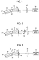
- FIG. 1 shows a structure of the embodiment.
- a resonator includes a gain medium 10 and a solid-state medium 20 having the wavelength-dependent dispersion opposite to that of the gain medium 10.
- Surfaces 11 and 21 of the gain medium 10 and the solid-state medium 20, which are not opposite to each other, are reflectively coated to the reflectance of about 99.9% in a wavelength of light oscillated, to thereby form end mirrors of the resonator.
- the oscillation light is in the vicinity of 1.5 ⁇ m and the representative of the solid-state medium 20 paired therewith is made of fused silica indicating a negative dispersion in a wavelength region thereof.
- a laser using the solid-state medium such as the Cr:YAG crystal as the gain medium 10 is generally named a solid-state laser and particularly a laser using the Cr:YAG crystal as the gain medium is named a Cr:YAG laser.
- the gain medium for all of Kerr-lens mode-locked solid-state lasers such as Ti:Al 2 O 3 , Cr:LiSrAlF 6 , Cr:Mg 2 SiO 4 , Yb:YAG, Yb:Ca 4 GdO(BO 3 ) 3 crystals, Yb:glass, Nd:glass or the like can be employed in addition to the Cr:YAG crystal.
- the kind of the solid-state medium 20 paired with the gain medium 10 must be selected in consideration of the dispersion in regard to the individual gain medium.
- a surface 22 of the solid-state medium 20, opposite to the gain medium 10 is polished to a curved surface so as to have the function of a lens, so that the stable resonator is obtained.
- a diameter of the beam is defined as a diameter at the place where the intensity is 1/e 2 of this value at the center of the beam
- the curvature of the surface 22 is designed so that a beam diameter 2w at the surface 11 of the gain medium is 0.1 mm or less.
- the beam diameter 2w is typically determined to be about 70 ⁇ m.
- the curved surface 22 is antireflectively coated to the transmittance of about 99.9% in a wavelength of light oscillated.
- the gain medium 10 is made of a Cr:YAG crystal having a length of 18 mm and the solid-state medium 20 is made of fused silica
- the length of the fused silica is properly about 10 to 20 mm and when a distance between the surfaces 22 and 12 is about 0 to 10 mm, the radius of curvature of the surface 22 is properly about 2 to 4 mm.
- the surface 12 of the gain medium 10, opposite to the solid-state medium 20 is polished to a plane surface and a polishing angle thereof can be selected from three kinds of angles.
- the reflectance is theoretically zero to polarization (p-polarization) in the paper surface of Fig. 1 and a loss in the surface 12 can be almost reduced to zero.
- the surface is coated antireflectively to the oscillation light in order to suppress reflection at the surface 12.
- the surface 12 is polished at a shifted angle of several degrees to the perpendicularly polished surface ( ⁇ gain ⁇ 0). In this case, the multiple reflection effect having a possibility of being produced in case of the perpendicular polishing can be suppressed. Further, since the third case is not symmetrical in rotation as in the perpendicular polishing, polarization of the light oscillated can be stabilized. Even in this case, since reflection occurs in the surface 12, the surface is antireflectively coated.
- Excitation of the laser resonator is attained by leading the excitation light from the excitation light source 30 to the gain medium 10.
- the excitation light is focused on the surface 11 of the gain medium 10 through a focusing lens 40.
- the distance between the excitation light source 30 and the surface 11 and the focal length of the focusing lens 40 are important particularly when an ultrashort pulse is oscillated.
- a beam diameter of the excitation light at the surface 11 is designed to be smaller than that of the resonator mode.
- the surface 11 is coated highly reflectively (for example, 99.9%) for the oscillation light whereas it is coated not to reflect the excitation light (it is desirable that the reflectance is zero but light is reflected about 5% actually).
- the excitation light source can use a laser diode, a solid-state laser, a gas laser or the like.
- the gain medium 10 is a Cr:YAG crystal
- the wavelength of the excitation light is desirably about 1.05 ⁇ m and Nd:YAG, Nd:YVO4, Nd:glass, Nd:YLF lasers or the like is proper as the excitation light source in addition to the laser diode.
- the output light is taken out from the surface 21 as shown in Fig. 1.
- the surface 21 is reflectively coated so that the output light is transmitted partially.
- the final transmissivity is different depending on a gain medium used but is smaller than or equal to several %. In the case of the Cr:YAG laser, the transmissivity of about 0.5% is used.
- the output light is taken out from the surface 11 as shown in Fig. 2.
- the surface 11 is reflectively coated so that the oscillation light is transmitted partially.
- the final transmissivity is different depending on a gain medium used but is smaller than or equal to several %. In the case of the Cr:YAG laser, the transmissivity of about 0.5% is used.
- the surface 21 is highly reflectively coated. Since the output light taken out from the surface 11 passes through the same optical path as the excitation light, it is necessary to separate the output light from the optical path for the excitation light by means of a dichroic mirror 50.
- the dichroic mirror 50 transmits the excitation light and reflects the output light.
- the output light from the surface 11 has a minimum beam diameter at the surface 11 and the beam diameter of the output light produced from the surface 11 spreads gradually. Accordingly, it is advantageous that a concave mirror is used as the dichroic mirror 50 so that the output light is collimated.
- the dichroic mirror 50 acts as a concave lens to the excitation light and it is necessary to select the fucusing lens 40 in consideration of the action of the dichroic mirror 50. Since the concave lens 50 is not vertical to the optical axis of the excitation light, an astigmatism occurs. The astigmatism can be compensated by tilting the focusing lens 40 in the same direction as the tilt direction of the concave lens 50 or in the reverse direction thereto as disclosed in Japanese Patent Application No. 12-34306.
- the surface 12 is polished while it is shifted slightly from the Brewster angle or the surface 12 is polished at an angle shifted from the perpendicular direction to the propagating direction of light so that it is antireflectively coated to have a slite reflective-component.
- the surface 12 is used as an output coupler. In this case, the surfaces 11 and 21 are highly reflectively coated to the oscillation light.
- the surfaces of the gain medium 10 are polished to the plane surfaces and one surface 22 of the solid-state medium 20 is polished to the curved surface so as to have the function of lens so that a stability region of the resonator is formed.
- the stable resonator can be formed.
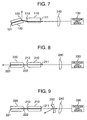
- three drawings are shown depending on how to take out the output light.
- a surface 122 of the solid-state medium 120 can be polished at the Brewster angle or perpendicularly to the propagating direction of light or at the shifted angle from the perpendicular direction.
- the radius of curvature of the curved surface 112 of the gain medium 110 may be about 6 mm for the Cr:YAG laser when a length of the gain medium is 18 mm, a fused silica of 13 mm is used as the solid-state medium 120, and a repetition rate is 2.4 GHz. This radius of curvature is about twice as larger as compared with the embodiment 1. The radius of curvature is determined so that the beam diameter at the surface 111 of the gain medium 110 is optimum.
- the lens formed by the curved surface is nearer to the surface 111 as compared with the embodiment 1, a lens having as short a focal length as in the embodiment 1 is not required and the radius of curvature of the surface 111 can be made larger. In this case, there are advantages that the spherical aberration is made small, polishing to a curved surface is made simple and the like
- one of the opposite surfaces of the gain medium and the solid-state medium is polished to the curved surface so as to have the function of lens so that a stability region of the resonator is formed.
- surfaces 212 and 222 of a gain medium 210 and a solid-state medium 220, which are opposite to each other are polished to curved surfaces, so that the stable resonator is formed.
- a coating method of the surfaces is the same as the embodiments 1 and 2.
- the output light is reflected by a dichroic mirror 250 in the same manner as the embodiments 1 and 2.
- a focusing lens 240 is tilted in order to compensate the astigmatism of the excitation light.
- Figs. 8 and 9 the inside of the resonator is symmetrical in rotation. There is a case where polarization of the oscillated light is not stabilized in the case of the symmetry in rotation, while by shifting the optical axis of the oscillated light from a center axis of rotation of the resonator, the symmetry in rotation collapses, so that the polarization can be stabilized in the same manner as the embodiments 1 and 2.
- the gain medium and the solid-state medium having the wavelength-dependent dispersion opposite to that of the gain medium are paired to form the resonator and by adjusting the length of the solid-state medium, a dispersion value in the resonator is set to a predetermined value.
- a chirped mirror for producing dispersion upon reflection is used instead of the solid-state medium (Figs. 10 and 11).
- An example of the solid-state laser using the chirped mirror is described in JP-A-11-168252 of the Inventors.
- the chirped mirror is formed of a multi-layer of dielectric or semiconductor and the thickness of the layers is changed gradually.
- the chirped mirror is accompanied by dispersion (e.g. N.
- the sign and the magnitude of the dispersion can be set to any values by controlling the thickness of the layers and are designed to be matched to the dispersion value of the gain medium.
- the function of lens is required in the resonator in order to form the stable resonator and this lens function is attained by polishing a surface 312 of a gain medium 310 to a curved surface.
- There are two kinds of methods of taking out the output light The output light is taken out from the chirped mirror side as shown in Fig. 10 or the output light is taken out from the gain medium side as shown in Fig. 11.
- a dichroic mirror 350 is used in the latter case and the method thereof is the same as the embodiments 1, 2 and 3.
- the inside of the resonator of Figs. 10 and 11 is symmetrical in rotation and there is a case where polarization is not stabilized, while by shifting the optical axis of the oscillation light from an axis of the symmetry in rotation, the symmetry collapses, so that the polarization can be stabilized.
- a Kerr-lens mode-locked solid-state laser can be operated spontaneously, while by providing a saturable absorber layer in the resonator, the mode-locked operation is further stabilized.
- the saturable absorber layer has the characteristic that the trasmissivity is high when the light intensity is high and the transmissivity is low when the light intensity is low. Accordingly, the transmissivity is high in a pulse portion where light is present and the transmissivity is reduced in a portion where there is no light, so that the saturable absorber layer acts to promote the pulse oscillation.
- the saturable absorber layer can be fabricated from a semiconductor (e.g. U. Keller, K. J. Weingarten, F. X. Kärtner, D. Kopf, B. Braun, I.
- the ultrafast pulse solid-state laser has a wide spectrum and it can be taken out at every wavelength to be used as a multi-wavelength light source for the wavelength-division-multiplexed optical transmission. This configuration is definitely shown in Fig. 12 in block.
- the optical transmission usually uses a wavelength of the 1.5 ⁇ m band and accordingly a solid-state laser suitable thereto is a Cr:YAG laser.
- An output of a solid-state laser 510 is led to a WDM splitter 520 composed of a diffraction grating or a waveguide type diffraction grating (e.g. A. Kaneko, T. Goh, H. Yamada, T. Tanaka, and I. Ogawa, IEEE. Journal of Selected Topics in Quantum Electronics, Vol.
- the separated wavelength components are led to individual modulators 530, respectively, and modulated by signals.
- the modulated wavelength components are combined in a WDM combiner 540 composed of a diffraction grating or a waveguide type diffraction grating to be transmitted.
- An optical transmitter 500 is formed by the above constituent elements.
- the wavelength components are combined into one signal by the WDM combiner 540 to be transmitted to a place, while there is a case where a destination for transmission is different depending on each wavelength for reasons of network management.
- the combiner is not provided as shown in Fig. 13 and the modulated wavelength components may be outputted in each wavelength.
- a bit rate of 2.4 GHz or 10 GHz is used usually.
- the ultrafast pulse solid-state laser of the embodiments 1 to 4 such a bit rate can be attained, while when another solid-state laser having the resonator length of 10 cm to several meters is used, the bit rate is made small.
- an output of the solid-state laser 510 is led to a time-division multiplexer 550 having the function of multiplying the repetition rate of a pulse by integral times so that the bit rate is increased.
- the configuration subsequent to the time-division multiplexer 550 is the same as that of Figs. 12 and 13.
- the time-division multiplexer 550 can be configured by various methods. The representatives thereof are shown in Figs. 16 to 18.
- the time-division multiplexer shown in Fig. 16 uses a delay line. An input light is divided into two optical paths 551 and 552 and then the divided light are combined. Since the optical paths 551 and 552 are different in length, a bit rate of the combined signal is twice. A pair of optical paths 553 and 554 and a pair of optical paths 555 and 556 are also operated similarly, so that the bit rate of a pulse train output from the time-division multiplexer of Fig. 16 is eight times as a whole.
- Fig. 17 shows an example of the time-division multiplexer 550 using a linearly-chirped fiber grating 557.
- An input light to the time-division multiplexer 550 is led to the linearly-chirped fiber grating 557 by means of an optical circulator 559.
- the input light is reflected while being accompanied by dispersion in the same manner as the chirped mirror in the linearly-chirped fiber grating 557.
- the reflected light is returned to the optical circulator again and outputted from the time-division multiplexer.
- An amount of dispersion set in the linearly-chirped fiber grating 557 is increased so that a pulse width is spread as a result of the dispersion and adjacent pulses overlap each other.
- the pulses are converted into a pulse train having the increased bit rate as a result of interference of the pulses.
- the method of setting the amount of dispersion is described in a paper: J. Azaa and M. A. Muriel, Optics Letters, Vol. 24, No. 23, pp. 1672-1674 (1999).
- the linearly-chirped fiber grating 557 is used to give dispersion to the pulse train, while the linearly-chirped fiber grating 557 is not necessarily required therefor and any dispersion medium 558 may be used as far as it gives a predetermined dispersion. It is shown in Fig. 18.
- the function of lens can be attained by polishing the gain medium or the solid-state medium to a curved surface, so that the ultrashort pulse solid-state laser having the small size and the high repetition rate can be provided. Further, by using the solid-state laser as a light source for a transmitter of the wavelength-division-multiplexed optical transmission, the number of light sources in the transmitter can be reduced greatly.
Landscapes
- Physics & Mathematics (AREA)
- Electromagnetism (AREA)
- Chemical & Material Sciences (AREA)
- Crystallography & Structural Chemistry (AREA)
- Engineering & Computer Science (AREA)
- Plasma & Fusion (AREA)
- Optics & Photonics (AREA)
- Lasers (AREA)
- Optical Communication System (AREA)
Abstract
By configuring the resonator only by two components (10,20), the required high repetition rate can be attained. Since each channel is produced passively from the splitter (520), very precise wavelength management is not required.
Description
Claims (24)
- A solid-state laser including an excitation light source (30), a lens system (40) for focusing an excitation light produced from said light source, and a laser resonator which is laser-oscillated in response to the focused excitation light, wherein said resonator comprises a gain medium (10) and a solid-state medium (20) having dispersion of a wavelength dependence opposite to that of said gain medium, and surfaces (11, 21) of said gain medium and said solid-state medium, which are not opposite to each other, are reflectively coated, at least one (22) of surfaces (12, 22) of said gain medium and said solid-state medium, which are opposite to each other, being polished to a curved surface, said gain medium being excited by said focused excitation light so that the laser oscillation is made in said resonator.
- A solid-state laser according to Claim 1, wherein said gain medium (10) is made of any of Cr:YAG, Ti:Al2O3, Cr:LiSrAlF6, Cr:Mg2SiO4, Yb:YAG and Yb:Ca4GdO(BO3)3 crystals, Yb:glass, and Nd:glass.
- A solid-state laser according to Claim 1, wherein if a diameter at a place where the intensity is 1/e2 of that on an optical axis of a resonator mode is defined as a diameter of a beam, a minimum diameter of the beam in said gain medium (10) is smaller than or equal to 0.1 mm.
- A solid-state laser according to Claim 1, wherein said excitation light source (30) is any of a laser diode, a gas laser and a solid-state laser.
- A solid-state laser according Claim 1, wherein said solid-state medium (20) having dispersion of the wavelength dependence opposite to that of said gain medium is any of fused silica, glass, MgF2 and CaF2.
- A solid-state laser according to Claim 1, wherein a surface (12) which is not polished to a curved surface, of two surfaces (12, 22) of said gain medium (10) and said solid-state medium (20), which are opposite to each other, is polished to a Brewster angle to the oscillation light.
- A solid-state laser according to Claim 1, wherein a surface (12) which is not polished to a curved surface, of two surfaces (12, 22) of said gain medium (10) and said solid-state medium (20), which are opposite to each other, is polished perpendicularly to a propagating direction of the oscillation light and is coated antireflectively.
- A solid-state laser according to Claim 1, wherein a surface (12) which is not polished to a curved surface, of two surfaces (12, 22) of said gain medium (10) and said solid-state medium (20), which are opposite to each other, is polished so that an incident angle of the oscillation light from the outside of said gain medium or said solid-state medium, to said surface which is not polished to the curved surface is larger than or equal to 0 degree and smaller than 90 degrees and is coated antireflectively.
- A solid-state laser according to Claim 1, wherein an output light of said resonator is any one or both of light transmitted from surfaces (11, 21) of said gain medium and said solid-state medium, which are not opposite to each other, and light reflected from a surface (12) which is not polished to a curved surface, of two surfaces (12, 22) of said gain medium and said solid-state medium (20), which are opposite to each other.
- A solid-state laser according to Claim 1, wherein an incident angle of the oscillation light from the outside of said gain medium (10) or said solid-state medium (20), to said surface which is polished to the curved surface, of said gain medium or said solid-state medium is larger than or equal to 0 degree and smaller than 90 degrees.
- A solid-state laser including an excitation light source (330), a lens system (340) for focusing an excitation light produced from said light source, and a laser resonator which is laser-oscillated in response to the focused excitation light, wherein said resonator comprises a gain medium (310) and a chirped mirror (360) having a dispersion of a wavelength dependence opposite to that of said gain medium, and a surface (311) of said gain medium (310), which is not opposite to said chirped mirror (360) is coated reflectively, a surface (312) of said gain medium, which is opposite to said chirped mirror, being polished to a curved surface, said gain medium being excited by said focused excitation light so that the laser oscillation is made in said resonator.
- A solid-state laser according to Claim 11, wherein said chirped mirror (360) is formed of a multi-layer of dielectric or semiconductor.
- A solid-state laser according to Claim 11, wherein said chirped mirror (360) includes a stacked structure of a multi-layer reflection coating accompanied by dispersion and a saturable absorber layer.
- A solid-state laser according to Claim 11, wherein said gain medium (310) is made of any of Cr:YAG, Ti:Al2O3, Cr:LiSrAlF6, Cr:Mg2SiO4, Yb:YAG, and Yb:Ca4GdO(BO3)3 crystals, Yb:glass, and Nd:glass.
- A solid-stage laser according to Claim 11, wherein if a diameter at a place where the intensity is 1/e2 of that on an optical axis of a resonator mode is defined as a diameter of a beam, a minimum diameter of the beam in said gain medium is smaller than or equal to 0.1 mm.
- A solid-state laser according to Claim 11, wherein said excitation light source (330) is any of a laser diode, a gas laser and a solid-state laser.
- A solid-state laser according to Claim 11, wherein an output light from said resonator is any one or both of light transmitted from a surface (311) of said gain medium (310) which is not opposite to said chirped mirror and light transmitted from said chirped mirror (360).
- A solid-state laser according to Claim 11, wherein an incident angle of the oscillation light from the outside of said gain medium (310), to said surface (312) which is polished to the curved surface, of said gain medium is larger than or equal to 0 degree and smaller than 90 degrees.
- An optical transmitter comprising a Kerr-lens mode-locked solid-state laser (510), a splitter (520) for splitting an output light of said solid-state laser in each wavelength, and modulators (530) each modulating said split light by a signal, to transmit said modulated light.
- An optical transmitter according to Claim 19, wherein said solid-state laser (510) comprises an excitation light source (30), a lens system (40) for focusing an excitation light produced from said light source, and a laser resonator including a gain medium (10) and a solid-state medium (20) having dispersion of a wavelength dependence opposite to that of said gain medium, and surfaces (11, 21) of said gain medium and said solid-state medium, which are not opposite to each other, are reflectively coated, at least one (22) of surfaces (12, 22) of said gain medium and said solid-state medium, which are opposite to each other, being polished to a curved surface, said gain medium being excited by said focused excitation light so that the laser oscillation is made in said resonator.
- An optical transmitter according to Claim 19, wherein said solid-state laser (510) comprises an excitation light source (330), a lens system (340) for focusing an excitation light produced from said light source, and a resonator including a gain medium (310) and a chirped mirror (360) having a dispersion of a wavelength dependence opposite to that of said gain medium, and a surface (311) of said gain medium, which is not opposite to said chirped mirror, is reflectively coated, a surface (312) of said gain medium, which is opposite to said mirror, being polished to a curved surface, said gain medium being excited by said focused excitation light so that the laser oscillation is made in said resonator.
- An optical transmitter comprising a Kerr-lens mode-locked solid-state laser (510), a time-division multiplexer (550) for multiplying a repetition rate of an output pulse train of said solid-state laser by integral times, a splitter (520) for splitting an output light of said time-division multiplexer in each wavelength, and modulators (530) each modulating said split light by a signal, to transmit said modulated light.
- An optical transmitter according to Claim 22, wherein said solid-state laser (510) comprises an excitation light source (30), a lens system (40) for focusing an excitation light produced from said light source, and a laser resonator including a gain medium (10) and a solid-state medium (20) having dispersion of a wavelength dependence opposite to that of said gain medium, and surfaces (11, 21) of said gain medium and said solid-state medium, which are not opposite to each other are reflectively coated, at least one (22) of surfaces (12, 22) of said gain medium and said solid-state medium, which are opposite to each other being polished to a curved surface, said gain medium being excited by said focused excitation light so that the laser oscillation is made in said resonator.
- An optical transmitter according to Claim 22, wherein said solid-state laser (510) comprises an excitation light source (330), a lens system (340) for focusing an excitation light produced from said light source, and a resonator including a gain medium (310) and a chirped mirror (360) having a dispersion of a wavelength dependence opposite to that of said gain medium, and a surface of said gain medium which is not opposite to said chirped mirror is reflectively coated, a surface (312) of said gain medium which is opposite to said chirped mirror being polished to a curved surface, said gain medium being excited by said focused excitation light so that the laser oscillation is made in said resonator.
Applications Claiming Priority (2)
| Application Number | Priority Date | Filing Date | Title |
|---|---|---|---|
| JP2000107973 | 2000-04-05 | ||
| JP2000107973A JP3858563B2 (en) | 2000-04-05 | 2000-04-05 | Solid-state laser capable of car lens mode synchronization |
Publications (2)
| Publication Number | Publication Date |
|---|---|
| EP1143581A2 true EP1143581A2 (en) | 2001-10-10 |
| EP1143581A3 EP1143581A3 (en) | 2004-09-15 |
Family
ID=18620894
Family Applications (1)
| Application Number | Title | Priority Date | Filing Date |
|---|---|---|---|
| EP00120122A Withdrawn EP1143581A3 (en) | 2000-04-05 | 2000-09-19 | Solid-state laser and optical transmitter |
Country Status (5)
| Country | Link |
|---|---|
| US (2) | US6560267B1 (en) |
| EP (1) | EP1143581A3 (en) |
| JP (1) | JP3858563B2 (en) |
| CN (1) | CN1316809A (en) |
| CA (1) | CA2319892A1 (en) |
Cited By (1)
| Publication number | Priority date | Publication date | Assignee | Title |
|---|---|---|---|---|
| WO2015059310A1 (en) * | 2013-10-25 | 2015-04-30 | Atla Lasers As | Graphene-based optical sub-system |
Families Citing this family (14)
| Publication number | Priority date | Publication date | Assignee | Title |
|---|---|---|---|---|
| JP3858563B2 (en) * | 2000-04-05 | 2006-12-13 | 株式会社日立製作所 | Solid-state laser capable of car lens mode synchronization |
| US7453486B2 (en) * | 2000-12-13 | 2008-11-18 | Orbotech Ltd | Pulse light pattern writer |
| WO2003028177A1 (en) * | 2001-09-24 | 2003-04-03 | Giga Tera Ag | Pulse-generating laser |
| US20030058904A1 (en) * | 2001-09-24 | 2003-03-27 | Gigatera Ag | Pulse-generating laser |
| KR100442658B1 (en) * | 2002-08-14 | 2004-08-02 | 삼성전자주식회사 | Light source device for wavelength division multiplexing optical communication system |
| EP1870972A1 (en) * | 2006-06-22 | 2007-12-26 | Fujifilm Corporation | Mode-locked laser device |
| JP2008028379A (en) * | 2006-06-22 | 2008-02-07 | Fujifilm Corp | Mode-locked laser device |
| AT505021B1 (en) * | 2006-06-27 | 2008-10-15 | Nxp Semiconductors Austria Gmb | MEMBRANLESS MICROPHONE WITH THE HELP OF LIGHT INTERFERENCE |
| JP2010045147A (en) * | 2008-08-12 | 2010-02-25 | Fujifilm Corp | Mode synchronous laser device, pulse laser light source device, and microscope device |
| JP2010103291A (en) * | 2008-10-23 | 2010-05-06 | Fujifilm Corp | Mode synchronous laser device |
| US9851570B2 (en) | 2014-09-18 | 2017-12-26 | Ipg Photonics Corporation | Beam shaping of high intensity high frequency optical output |
| WO2017175344A1 (en) * | 2016-04-07 | 2017-10-12 | ギガフォトン株式会社 | Solid-state laser device, solid-state laser system, and laser device for light exposure device |
| CN105932534A (en) * | 2016-06-17 | 2016-09-07 | 北京国科世纪激光技术有限公司 | Intracavity frequency doubling astigmatism compensation type laser |
| JP2024137115A (en) * | 2023-03-24 | 2024-10-07 | ソニーグループ株式会社 | Laser elements and electronic devices |
Family Cites Families (12)
| Publication number | Priority date | Publication date | Assignee | Title |
|---|---|---|---|---|
| US5212698A (en) * | 1990-05-02 | 1993-05-18 | Spectra-Physics Lasers, Incorporated | Dispersion compensation for ultrashort pulse generation in tuneable lasers |
| US5856996A (en) * | 1992-12-07 | 1999-01-05 | The United States Of America As Represented By The Secretary Of The Air Force | Compact efficient solid state laser |
| WO1995031023A1 (en) * | 1994-05-09 | 1995-11-16 | Massachusetts Institute Of Technology | Dispersion-compensated laser using prismatic end elements |
| US5586996A (en) | 1994-05-12 | 1996-12-24 | Manookian, Jr.; Arman K. | Vapor separating device |
| US5761227A (en) * | 1994-08-23 | 1998-06-02 | Laser Power Corporation | Efficient frequency-converted laser |
| DE19603637C1 (en) * | 1996-02-01 | 1997-07-31 | Lambda Physik Gmbh | Narrow band radiation emitting laser |
| US5912915A (en) * | 1997-05-19 | 1999-06-15 | Coherent, Inc. | Ultrafast laser with multiply-folded resonant cavity |
| JPH11168252A (en) * | 1997-12-05 | 1999-06-22 | Hitachi Ltd | Small solid-state laser |
| US6229835B1 (en) * | 1997-12-05 | 2001-05-08 | Hitachi, Ltd. | Compact solid-state laser and transmitter using the same |
| US6393037B1 (en) * | 1999-02-03 | 2002-05-21 | Lambda Physik Ag | Wavelength selector for laser with adjustable angular dispersion |
| US6393035B1 (en) * | 1999-02-01 | 2002-05-21 | Gigatera Ag | High-repetition rate passively mode-locked solid-state laser |
| JP3858563B2 (en) * | 2000-04-05 | 2006-12-13 | 株式会社日立製作所 | Solid-state laser capable of car lens mode synchronization |
-
2000
- 2000-04-05 JP JP2000107973A patent/JP3858563B2/en not_active Expired - Fee Related
- 2000-09-15 CA CA002319892A patent/CA2319892A1/en not_active Abandoned
- 2000-09-19 US US09/665,619 patent/US6560267B1/en not_active Expired - Fee Related
- 2000-09-19 EP EP00120122A patent/EP1143581A3/en not_active Withdrawn
- 2000-09-20 CN CN00128674.9A patent/CN1316809A/en active Pending
-
2003
- 2003-04-23 US US10/420,902 patent/US6754248B2/en not_active Expired - Fee Related
Cited By (2)
| Publication number | Priority date | Publication date | Assignee | Title |
|---|---|---|---|---|
| WO2015059310A1 (en) * | 2013-10-25 | 2015-04-30 | Atla Lasers As | Graphene-based optical sub-system |
| US10333266B2 (en) | 2013-10-25 | 2019-06-25 | Alta Lasers As | Graphene-based optical sub-system |
Also Published As
| Publication number | Publication date |
|---|---|
| US6754248B2 (en) | 2004-06-22 |
| EP1143581A3 (en) | 2004-09-15 |
| US20030210730A1 (en) | 2003-11-13 |
| US6560267B1 (en) | 2003-05-06 |
| JP2001291918A (en) | 2001-10-19 |
| CA2319892A1 (en) | 2001-10-05 |
| CN1316809A (en) | 2001-10-10 |
| JP3858563B2 (en) | 2006-12-13 |
Similar Documents
| Publication | Publication Date | Title |
|---|---|---|
| US6560267B1 (en) | Solid-state laser and optical transmitter | |
| US6097741A (en) | Passively mode-locked fiber lasers | |
| US20230170664A1 (en) | Method and Device for Altering Repetition Rate in a Mode-Locked Laser | |
| US5689519A (en) | Environmentally stable passively modelocked fiber laser pulse source | |
| EP0571051A1 (en) | Solid state microlaser | |
| US7103076B2 (en) | Ultrashort pulsed laser and optical head using the same | |
| JP2013077831A (en) | Modular fiber-based chirped pulse amplification system | |
| US6307872B1 (en) | Compact solid-state laser and transmitter using the same | |
| US6967976B2 (en) | Laser with reflective etalon tuning element | |
| CN110600984A (en) | Wavelength-adjustable passive mode-locking fiber laser | |
| US5889798A (en) | Active-switching laser and microchip laser | |
| US20090041062A1 (en) | Fiber-based tunable laser | |
| JPH11168252A (en) | Small solid-state laser | |
| EP1186078B1 (en) | Diode laser-pumped solid state laser | |
| US6351484B1 (en) | Output couplers for lasers | |
| US20250167506A1 (en) | Laser amplifier utilizing multiple end pump spots and method of manufacture | |
| JP2004165652A (en) | Ultrashort pulse laser device and optical head using the same | |
| US6959023B1 (en) | Laser with reflective etalon tuning element | |
| JPWO2006132285A1 (en) | light source | |
| US20060056465A1 (en) | Laser with reflective etalon tuning element | |
| US20190006811A1 (en) | Laser device with an optical resonator and method for adjusting the laser device | |
| JP2009016607A (en) | Mode-locked laser device | |
| EP1487072B1 (en) | Transversely pumped laser | |
| EP1037336A2 (en) | Solid-state laser compensated for pumping-light astigmatism | |
| WO2001005004A1 (en) | Wavelength tunable, polarization stable mode-locked fiber laser |
Legal Events
| Date | Code | Title | Description |
|---|---|---|---|
| PUAI | Public reference made under article 153(3) epc to a published international application that has entered the european phase |
Free format text: ORIGINAL CODE: 0009012 |
|
| AK | Designated contracting states |
Kind code of ref document: A2 Designated state(s): AT BE CH CY DE DK ES FI FR GB GR IE IT LI LU MC NL PT SE |
|
| AX | Request for extension of the european patent |
Free format text: AL;LT;LV;MK;RO;SI |
|
| PUAL | Search report despatched |
Free format text: ORIGINAL CODE: 0009013 |
|
| AK | Designated contracting states |
Kind code of ref document: A3 Designated state(s): AT BE CH CY DE DK ES FI FR GB GR IE IT LI LU MC NL PT SE |
|
| AX | Request for extension of the european patent |
Extension state: AL LT LV MK RO SI |
|
| 17P | Request for examination filed |
Effective date: 20050307 |
|
| AKX | Designation fees paid |
Designated state(s): DE FR GB IT |
|
| 17Q | First examination report despatched |
Effective date: 20080215 |
|
| STAA | Information on the status of an ep patent application or granted ep patent |
Free format text: STATUS: THE APPLICATION IS DEEMED TO BE WITHDRAWN |
|
| 18D | Application deemed to be withdrawn |
Effective date: 20080626 |