EP1143460A1 - Surge arrester - Google Patents
Surge arrester Download PDFInfo
- Publication number
- EP1143460A1 EP1143460A1 EP01108390A EP01108390A EP1143460A1 EP 1143460 A1 EP1143460 A1 EP 1143460A1 EP 01108390 A EP01108390 A EP 01108390A EP 01108390 A EP01108390 A EP 01108390A EP 1143460 A1 EP1143460 A1 EP 1143460A1
- Authority
- EP
- European Patent Office
- Prior art keywords
- surge arrester
- insulating
- electrode terminals
- nonlinear resistive
- arrester
- Prior art date
- Legal status (The legal status is an assumption and is not a legal conclusion. Google has not performed a legal analysis and makes no representation as to the accuracy of the status listed.)
- Granted
Links
Images


Classifications
-
- A—HUMAN NECESSITIES
- A01—AGRICULTURE; FORESTRY; ANIMAL HUSBANDRY; HUNTING; TRAPPING; FISHING
- A01M—CATCHING, TRAPPING OR SCARING OF ANIMALS; APPARATUS FOR THE DESTRUCTION OF NOXIOUS ANIMALS OR NOXIOUS PLANTS
- A01M29/00—Scaring or repelling devices, e.g. bird-scaring apparatus
- A01M29/06—Scaring or repelling devices, e.g. bird-scaring apparatus using visual means, e.g. scarecrows, moving elements, specific shapes, patterns or the like
-
- H—ELECTRICITY
- H01—ELECTRIC ELEMENTS
- H01T—SPARK GAPS; OVERVOLTAGE ARRESTERS USING SPARK GAPS; SPARKING PLUGS; CORONA DEVICES; GENERATING IONS TO BE INTRODUCED INTO NON-ENCLOSED GASES
- H01T4/00—Overvoltage arresters using spark gaps
-
- A—HUMAN NECESSITIES
- A01—AGRICULTURE; FORESTRY; ANIMAL HUSBANDRY; HUNTING; TRAPPING; FISHING
- A01M—CATCHING, TRAPPING OR SCARING OF ANIMALS; APPARATUS FOR THE DESTRUCTION OF NOXIOUS ANIMALS OR NOXIOUS PLANTS
- A01M29/00—Scaring or repelling devices, e.g. bird-scaring apparatus
- A01M29/06—Scaring or repelling devices, e.g. bird-scaring apparatus using visual means, e.g. scarecrows, moving elements, specific shapes, patterns or the like
- A01M29/08—Scaring or repelling devices, e.g. bird-scaring apparatus using visual means, e.g. scarecrows, moving elements, specific shapes, patterns or the like using reflection, colours or films with specific transparency or reflectivity
-
- A—HUMAN NECESSITIES
- A01—AGRICULTURE; FORESTRY; ANIMAL HUSBANDRY; HUNTING; TRAPPING; FISHING
- A01M—CATCHING, TRAPPING OR SCARING OF ANIMALS; APPARATUS FOR THE DESTRUCTION OF NOXIOUS ANIMALS OR NOXIOUS PLANTS
- A01M29/00—Scaring or repelling devices, e.g. bird-scaring apparatus
- A01M29/24—Scaring or repelling devices, e.g. bird-scaring apparatus using electric or magnetic effects, e.g. electric shocks, magnetic fields or microwaves
- A01M29/26—Scaring or repelling devices, e.g. bird-scaring apparatus using electric or magnetic effects, e.g. electric shocks, magnetic fields or microwaves specially adapted for birds, e.g. electrified rods, cords or strips
-
- H—ELECTRICITY
- H01—ELECTRIC ELEMENTS
- H01C—RESISTORS
- H01C7/00—Non-adjustable resistors formed as one or more layers or coatings; Non-adjustable resistors made from powdered conducting material or powdered semi-conducting material with or without insulating material
- H01C7/10—Non-adjustable resistors formed as one or more layers or coatings; Non-adjustable resistors made from powdered conducting material or powdered semi-conducting material with or without insulating material voltage responsive, i.e. varistors
- H01C7/12—Overvoltage protection resistors
- H01C7/126—Means for protecting against excessive pressure or for disconnecting in case of failure
Definitions
- the present invention relates to a surge arrester by the use of a nonlinear resistive element, which is mainly composed of a zinc oxide. Further, the present invention particularly relates to a surge arrester of a type that a resin (polymer) material is used as an insulative container.
- a nonlinear resistive element As an internal element of this surge arrester, a nonlinear resistive element is used, which represents an insulating property when a normal voltage is applied and represents a low resistance property when the unusual voltage is applied. Depending on a property of this nonlinear resistive element, when the unusual voltage occurs, a discharge current flows through the surge arrester, so that the unusual voltage is limited. Then, when the voltage returns to a normal state, the discharge current immediately stops and the voltage returns to original insulated state.
- FIG. 1 is a schematic cross sectional view for showing an example of a conventional surge arrester.
- a plurality of nonlinear resistive elements (zinc oxide elements) 1 which are mainly composed of zinc oxides, are stacked in a predetermined direction, so that a lamination layer is formed. Then, disposing electrode terminals 2 at an upper terminal and a lower terminal of this lamination layer, internal elements of the surge arrester are formed.
- the surge arrester is configured in such a manner of housing these internal elements of the surge arrester in an insulation tube 21 having a space 3a for discharging a voltage at their side face and covering this insulation tube 21 with an insulative container 22 made of a polymer resin.
- the surge arrester configured as described above, in the case that the nonlinear resistive elements 1 are damaged by the voltage, which exceeds its obligation, and further, an earth fault current flows through the internal elements within the surge arrester, the current which originally flowed through the nonlinear resistive elements 1 in the internal elements in the surge arrester turns out an arc 23.
- an inner voltage of the insulation tube 21 increases and this increased voltage is discharged from the space 3a for discharging a voltage through the insulative container 22, so that the surge arrester is prevented from bursting up.
- the insulative container 22 made of a polymer resin is particularly referred to as a polymer type surge arrester.
- a polymer type surge arrester has more flexibility in design compared with a surge arrester by the use of an insulative container made of a ceramic. Further, since this polymer type surge arrester has an advantage such as a narrower gap within the insulative container 22 or the like, it has a good prospect with respect to both of productivity and capability, so that development of this polymer type surge arrester is further expected.
- a conventional surge arrester as shown in FIG. 1 involves the following problems. At first, as shown in FIG. 1, the space 3a for discharging a voltage functions as an outlet of the arc 23 which is generated within the insulative container 22. However, since the conventional surge arrester is configured on the insulation tube 21, it should secure the strength in an axial of the insulation tube 21. Therefore, its position is materially limited.
- the space 3a which only can be disposed on a limited position is not capable of exerting the discharging function sufficiently, so that there is a possibility such that the electrode terminals 2 deviate by a high voltage within the insulative container 22 and the surge arrester internal elements such as the nonlinear resistive elements 1 or the like is darted out from the insulation tube 21 and the insulation tube 21 is blow out.
- the surge arrester by the use of the insulative container 22 made of a polymer resin, since the feathered creature such as a crow pecks a cap of the insulative container 22, this involves a problem such that the insulating property of the surge arrester is decreased.
- An object of the present invention is to provide a surge arrester, which can relieve the internal pressure, and whose failure is not likely to cause an explosive failure, when the nonlinear resistive element is broken up due to the exceed voltage and the earth current flows within the surge arrester and has an excellent property for discharging voltage, an excellent property for boiling resistance, safety and a high reliability of long duration without infiltrating the moisture.
- Another object of the present invention is to provide a surge arrester, which is also capable of preventing a damage by the feathered creature such as a crow and has a higher reliability in addition to prevention of burst up, shatter and infiltrate of the moisture.
- the surge arrester of the present invention in accordance with claim 1 comprises at least one nonlinear resistive element made mainly of zinc oxide and having two ends and one axis;
- this constitution it is possible to form an opening which extends in a direction of an axis of the surge arrester between the insulation supporting elements, so that, in the case that the nonlinear resistive elements 1 are damaged by the voltage which exceeds its allowance, and further, an earth fault current flows through the internal elements in the surge arrester, the internal pressure is capable of being discharged sufficiently from the opening, which extends in a direction of its axis. Therefore, an excellent pressure discharging property can be obtained and burst up and shatter of the surge arrester can be prevented.
- the surge arrester since the construction of the surge arrester is simple and a silicone resin with an excellent flow property is used, the surge arrester is capable of easily being molded in various shapes without applying excess power to internal elements of the surge arrester, so that gaps and air bubbles in an internal of the surge arrester can be decreased. Therefore, an excellent property for boiling resistance can be obtained and the moisture is prevented from being infiltrated in an internal of the surge arrester under a harsh condition.
- the arrester according to claim 1 wherein the insulating supports are secured to the electrode terminals by one of a method selected from the group consisting of a method using bolts, a method of using projections protruding from the ends of the insulating support and holes made in the electrode terminals and a method of bonding the insulating supports to the electrode terminals.
- the surge arrester can be easily composed. Particularly, in the case that they are fixed only by fitting and bonding, the number of parts can be omitted. Further, in this case, since there is no step for fixing by a bolt, the composing operation can be easier and economical efficiency becomes higher.
- the arrester according to claim 1 or 2 wherein a metal plate is interposed between at least one of the electrode terminals and the nonlinear resistive element, the at least one of the electrode terminals has a screw hole, and a screw is set in screw engagement with the screw hole and functions as a jack when rotated to push the metal plate.
- a compression loading which is applied to the nonlinear resistive element can be appropriately managed, since the usage of a plurality of springs with various strengths enables to absorb the compression loading which is applied to the nonlinear resistive element by expansion and contraction depending on the temperature change of the insulates supporting element with a larger coefficient of thermal expansion by using a plurality of springs.
- the arrester according to any one of claims 1 to 4, wherein the insulating supports are made of plastic reinforced plastic with mesh fiber.
- the arrester according to any one of claims 1 to 5, wherein the nonlinear resistive element is covered with a plastic layer reinforced with mesh fiber.
- the usage of FRP enables to improve the strength of insulation supporting of the internal elements of the surge arrester.
- the nonlinear resistive element is covered with a mesh fiber reinforced plastic (FRP) as described in claim 6, it is possible to prevent small fractions of the damaged zinc oxide element from flying out from the opening between the insulation supporting elements even when the nonlinear resistive element is damaged by the short circuit current.
- FRP mesh fiber reinforced plastic
- the arrester according to claim 7 wherein the epoxy resin layer covers each of the insulating supports, except that part thereof to which an electric current is supplied, and the circumferential surface of each of the insulating supports.
- the arrester in accordance with claim 9, the arrester according to any one of claims 1 to 8, wherein the insulating container has a substantially polygonal cross section, and the insulating supports are arranged at every other side or every other apex of the substantially polygonal cross section.
- the arrester according to claim 9 wherein the any side of the insulating container that contacts one insulating support is thicker than any other side of the insulating container.
- the arrester according to claim 9 wherein the any side of the insulating container that contacts one insulating support is 2 to 5 mm at the thinnest part.
- the thickness of the silicone resin is in the range of 2 and 5 mm as described in claim 11. This is why the silicone resin is easily damaged when the thickness thereof is less than 2 mm and the internal pressure thereof is increased if the thickness thereof exceeds 5 mm when the short circuit current flows.
- the arrester according to any one of claims 1 to 12, wherein a pattern is provided on an outer circumferential surface of the insulating container, the pattern being one selected from the group consisting of a pattern composed of stripes of the same color, a pattern composed of strips alternately of two colors complement to each other, a pattern representing a natural enemy of birds that may fly toward the arrester and a pattern composed of at least two of the three patterns mentioned.
- the arrester according to any one of claims 1 to 13, further comprising a bracket for fastening the arrester to a pole, the bracket having a plurality of pyramidal projections on one surface.
- a pattern such that complementary colors are distributed alternatively and a pattern representing a natural enemy of potential birds which may come by air on surfaces of the insulative containers it is possible to prevent the birds from approaching to the insulative containers.
- a concavo-convex portion including an angular portion is formed on an arm of a bracket, on which the surge arrester, it is possible to prevent the birds from settling in the vicinity of the surged arrester.
- the surged arrester comprises a plurality of slender insulation supporting elements, which are disposed to a circumference of the nonlinear resistive element and are fixed to the electrode terminals and insulative containers, which is shaped in a mold by a silicone resin around the nonlinear resistive element and the insulation supporting elements, it is possible to discharge the internal pressure sufficiently and it is possible to prevent the surged arrester from bursting up and shatter in the case that the nonlinear resistive element is damaged by the excessive voltage, the earth fault current flows through the internal of the surged arrester and the moisture is not infiltrated in the internal of the surged arrester. Therefore, the present invention is capable of providing a surged arrester having an excellent discharge pressure property, an excellent property for boiling resistance, safety and a high reliability of long duration.
- the caps of the insulation containers made of a silicone resin representing a pattern on the surface of the insulative containers and devising the arm or the like of the bracket, on which the surge arrester is disposed, it is possible to provide a surged arrester having a higher reliability, which is capable of preventing the damages by the feathered creature such as a crow as well as preventing the burst out thereof, shatter thereof and insertion of the moisture therein.
- FIGS. 1 to 4 An embodiment applying a surge arrester according to the present invention will be specifically explained with reference to FIGS. 1 to 4 below.
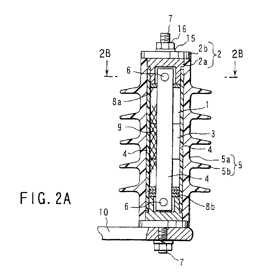
- FIGS. 2A to 2C are views for showing an example of a surge arrester applying a first embodiment of the present invention.
- a lamination layer is formed by laminating a plurality of nonlinear resistive elements (zinc oxide elements) 1 in a predetermined direction and the surge arrester internal elements are formed by disposing electrode terminal 2, which are composed of a fixing portion 2a and a plate portion 2b, at an upper edge and a lower edge of this lamination layer, respectively.
- a plurality of slender and plate type insulation supporting elements 4 which have rigidity and are made of fiber reinforced plastic (FRP) are disposed around the nonlinear resistive elements 1 in such a manner that they define a plurality of space 3, which extend in an axis direction of the surge arrester and these insulation supporting elements 4 are fixed to the electrode terminals 2 on the opposite sides. Then, by molding a periphery of the nonlinear resistive elements 1 and the insulation supporting elements 4 with a silicone resin which has an excellent flow property, an insulative container 5 which is composed of a drum portion 5a and a cap portion 5b is formed.
- FRP fiber reinforced plastic
- the insulative container 5 is molded as described below.
- the electrode terminals 2 are connected to the opposite edges in an axial direction of the nonlinear resistive elements 1. Simultaneously, housing the electrode terminals 2, to which a plurality of the insulation supporting elements 4 are fixed, in a mold and filling a liquid silicone resin in this mold, the insulative containers 5 and the nonlinear resistive elements 1 are entirely surrounded. Then, the insulative container 5 is molded so that the portions of the electrode terminals 2 are exposed.
- the insulation supporting element 4 is fixed to the fixing portion 2a of the electrode terminal 2, for example, by a plate screw 6.
- This fixation may be performed by, a knocking pin, such that a metal is spread in a rivet shape in the inner space by knocking with a hammer.
- this knocking pin since the air space of a screw hole or the like is vanished, it becomes possible to fix them steady without blurring.
- the insulation supporting element 4 is fixed to respective one position of the upper and lower edges by plate screw 6 in FIGS. 2A to 2C, it is desirable that the insulation supporting element 4 is fixed to more than two positions of the upper and lower edges, respectively.
- Embedded screws 7 for adjusting spacing are disposed on the electrode terminals 2 on the opposite sides, respectively, so that they are capable of being screwed.
- a screw hole (not illustrated), in which the embedded screw 7 is infiltrated, is defined on the fixing portion 2a and the plate portion 2b, which compose the electrode terminal 2 and a female screw (not illustrated) is formed on this screw hole.
- a nut 16 is fitted in a portion, which is prominent from the electrode terminal 2 of the embedded screw 7, through a chip plate 15 in order to connect a lead wire for connecting the surge arrester, for example, between the non-illustrated electric system and the earth.
- a metal caul 8a is disposed between the electrode terminal 2 at the upper edge and the nonlinear resistive elements 1.
- the surge arrester is constructed surge arrester when the metal caul 8a is pressed by the screw 7.
- a plurality of springs 8b with various strengths are arranged between the electrode terminal 2 at the lower edge and the nonlinear resistive elements 1.
- a space for compression of a metal caul 8a is left between the electrode terminal 2 at the upper edge and the nonlinear resistive elements 1.
- the nonlinear resistive elements 1 is covered with a mesh 9 made of the fiber reinforced plastic (FRP).
- the reference numeral 10 shows an arm 10 of a bracket for disposing the surge arrester on an electric pole or the like.
- the short circuit test was carried out by applying the excessive voltage for a short time and carrying the short circuit current, 10 kA, for 0.2 s after electrically destroying the nonlinear resistive elements 1.
- a side face of the insulative container 5 is tore, so that the rising inner pressure is capable of being effectively released.
- the space 3 which extends to the axis direction of the surge arrester is defined. Further, there is nothing to suppress the rising of the inner pressure upon carrying the short circuit current, so that the inner pressure is extremely not risen. In other words, upon discharging the pressure, the fragments or the like of the nonlinear resistive elements 1 were not flew out to the outside, so that it was deemed that the inner pressure was capable of being sufficiently discharged from the space 3, which extended to the axis direction of the surge arrester.
- the nonlinear resistive elements 1 is covered with the mesh 9 made of FRP, it was deemed that small fragments of the nonlinear resistive elements 1, which was destroyed by the short circuit current, were efficiently prevented from flying out from a gap of the insulation supporting elements.
- the surge arrester according to the first embodiment has a simple construction and especially, the insulative container 5 is made of a silicone resin having an excellent flow property by molding, so that it is possible that the surge arrester according to the first embodiment is easily molded into various forms without providing the excessive power to the inside of the surge arrester and the generation of the places where the infiltrated moisture is accumulate, such as the gaps and the air bubbles in the inside of the nonlinear resistive elements 5, is decreased. Thus, it can be seemed that the electric property of the surge arrester is not lowered even when it is soaked in the boiled water.
- the mesh 9 and the insulation supporting elements 4, which are disposed around the nonlinear resistive elements 1, are made of the FRP, there is an advantage such that the insulation supporting strength in the inside of the surge arrester can be improved.
- applying an epoxy coating on a side face of the nonlinear resistive elements 1 may be considered.
- the change of the electric property was further smaller than that of the first embodiment except for the nonlinear resistive elements 1 when the same salt water boiling test was carried out with respect to the surge arrester having the same construction as the first embodiment.
- applying an epoxy coating not only on a side face of the nonlinear resistive elements 1, but also to the all elements of the inside of the surge arrester composed of the nonlinear resistive elements 1 and the electrode terminals 2 except for the current carrying portions and to the periphery of the insulation supporting elements 4 may also be considered.
- the portions except for the above portions the further excellent results were obtained such that there is little or nothing lowering of the electric property when the same salt water boiling test was carried out with respect to the surge arrester having the same construction as the first embodiment.
- FIGS. 3A to 3C are views for showing an example of a surge arrester applying a second embodiment of the present invention.
- the insulation supporting elements 4 and the fixing portions 2a of the electrode terminals 2 are fixed by fitting prominences 11, which are disposed on the opposite edges of the insulation supporting elements 4, with holes, which are defined in the fixing portions 2a of the electrode terminals 2 in place of the usage of the bolts 6 in the surge arrester according to the first embodiment.
- the portions except for the above are constructed in the same way as those of the first embodiment.
- the surge arrester of the present embodiment When manufacturing the surge arrester of the present embodiment having such a construction and carrying out the same short circuit test and the same salt water boiling test, the excellent results were obtained in the same way. Therefore, according to the present embodiment, the same effect as that of the first embodiment can be obtained. Additionally, according to the present embodiment, there is an advantage such that it has a good economical efficiency and a good operability since few parts are required and no step for a bolt fixation is required in the case that the fixing method by the use of fitting is employed. Alternatively, as a modified example of the present embodiment, it may be considered that the adhesive is applied to the fitting portion between the electrode terminals 2 and the insulation supporting elements 4 so that they are bonded. Also, in this case, a good result was obtained when the surge arrester was manufactured in actual and the same test was carried out.
- a third embodiment of the present invention has a construction such that the outline of the electrode terminals 2 are regular polygon, ing., e.g. regular hexagon and the insulative containers thereof 5 are polygon e.g., hexagon and the insulation supporting elements 4 are disposed for every other side of the polygon which is an electrode terminal.
- the thickness of a silicone resin in a portion, in which the insulation supporting element 4 is not interposed is thinner than the thickness of a silicone resin in a portion, in which the insulation supporting element 4 is interposed, with respect to the thickness of a silicone resin between the nonlinear resistive elements 1 and surfaces of the insulative containers 5 (a thinner silicone resin layer 13).
- a thinner silicone resin layer 13 even the thinnest portion of the thinner silicone resin layer 13 is in the range of 2 to 5 mm.
- Other portions except for this are constructed in the same way as the first embodiment. If the polygon approximates a circle, the thickness of a resin in a side portion 12 (i.e.
- the thickness of the silicone resin layer 13), in which the insulation supporting element 4 is not interposed is thicker compared with the thickness of the resin in a side portion, in which the insulation supporting element 4 is interposed, by the thickness of the insulation supporting element 4. Therefore, a triangle shown in FIGS. 4A to 4D is particularly desirable among the polygons in regard to the construction and the manufacturability. However, if the polygon is a square (not illustrated), cutting off the opposite edges of the insulation supporting elements 4, it is possible to make the thickness of the resin of the side portion 12, in which the insulation supporting element 4 is not interposed, i.e., the thickness of the silicone resin layer 13, thinner from the view of the construction.
- the third embodiment it is also possible to improve the discharge pressure property in addition to obtaining the same effect as that of the first embodiment.
- a construction may be considered such that the insulation supporting elements 4 are disposed on the vertexes of the polygon so that the thickness of the silicone resin in the side portion of the polygon is thinner. Also, in this case, when manufacturing a surge arrester of the present embodiment in actual and carrying out the same short circuit test and the same salt water boiling test, the good results were obtained in the same way.
- the thickness of the silicone resin is desirable in the range of 2 to 5 mm at the thinnest portion of the polymer of the entire surge arrester. This is the reason why the polymer of the thickness less than 2 mm is easily damaged and the inner pressure very rises in the polymer of the thickness more than 5 mm upon carrying the short circuit current.
- the disposing position of the lope-shaped silicone rubber may be any place of the silicone resin layer 13 if it can be a start point for discharging the pressure, it is desirable that the lope-shaped silicone rubber is disposed in the vicinity of a center of the silicone resin layer 13. This is the reason why it becomes easier to discharge the pressure as the lope-shaped silicone rubber is disposed closer to a center of the silicone resin layer 13.
- a portion having prominences such that their diameters gradually increase may be disposed on a portion of the side portion 12, which is a spacer between the nonlinear resistive elements and in which the insulation supporting elements 4 are not infiltrated.
- the silicone rubber covering this prominent portion becomes thinner, so that the silicone rubber covering this prominent portion becomes a start point for discharging the pressure and further, it becomes possible to prevent the surge arrester from being bursting up and being shattered.
- the insulative containers 5 have cap portions, of which length is not less than 5 cm and of which spacing is not more than 5 cm and concave-convex portions 10a including the angle portion are disposed on an arm 10 of a bracket.
- the other portions except for this are constructed in the same way as the first embodiment.
- the length and the spacing of the cap portions 5b of the insulative containers 5 are defined appropriately, so that it is possible to prevent a pecker of a bird 14, which has the habit of pecking something like a trunk of a tree in a columnar shape with an appropriate flexibility, from reaching to a drum of the insulative container 5.
- the convaco-convex portions 10a including the angle portion are disposed on an arm 10 of a bracket, to which the surge arrester is disposed, it is possible to physically prevent the birds from settling on the vicinity of the insulative containers 5. Therefore, the damage of the surged arrester by the birds and the contamination thereof by the feces of the birds are capable of being prevented by a synergy effect and it is possible to vanish a possibility that the moisture is infiltrated within the surge arrester.
- the invention in accordance with the invention set forth in may be considered as a modified example of the fourth embodiment.
- a pattern so as to visually prevent the bird from approaching to the surged arrester is displayed on the surfaces of the insulative containers 5, such as a mesh pattern, a pattern such that complementary colors are distributed alternatively and a pattern representing a natural enemy of potential birds which may come by air.
- picturing a pattern, a face and an eye or the like of a snake, which is a natural enemy of the bird, on the surfaces of the insulative containers 5 may be considered.
- the present invention is not limited to respective embodiments as described above. However, the present invention may be applied to various embodiments within a scope of the present invention in addition to the above described embodiments.
- the surge arrester has at least a plurality of slender insulation supporting elements, which are disposed to a circumference of the nonlinear resistive elements and are fixed to the electrode terminals and the insulative containers, which are molded around the nonlinear resistive elements and the insulation supporting elements and are made of a silicone resin, the constitution of the nonlinear resistive element and the insulation supporting element, the detailed constitution of the insulative container or the like and the constitutions of the other portions may be freely selected. In any case, the excellent effect is capable of being obtained in the same way as the above described embodiments.
- the nonlinear resistive element may not be limited to this but it may be an any form such as an ellipse, a trainable, a rectangular and a polygon. Additionally, it is exemplified and explained that a plurality of the nonlinear resistive elements 1 is stacked in a layer in a predetermined direction. However, without being limited to this, an example such that one nonlinear resistive elements 1 is disposed may be applied to the present invention.
Abstract

Description
Claims (14)
- An arrester characterized by comprising:at least one nonlinear resistive element (1) made mainly of zinc oxide and having two ends and one axis;at least two electrode terminals (2) electrically connected to the two ends of said at least one nonlinear resistive element (1), respectively;a plurality of elongated insulating supports (4) arranged around the nonlinear resistive element (1), extending parallel to the axis of the nonlinear resistive element (1) and spaced apart from one another, each insulating support (4) having both ends secured to the electrode terminals (2); andan insulating container (5) made of silicone resin and formed by molding, surrounding the nonlinear resistive element (1) and the insulating supports (4), and exposing parts of the electrode terminals (2).
- The arrester according to claim 1, characterized in that the insulating supports (4) are secured to the electrode terminals (2) by one of a method selected from the group consisting of a method using bolts, a method of using projections protruding from the ends of the insulating support (4) and holes made in the electrode terminals (2) and a method of bonding the insulating supports (4) to the electrode terminals (2).
- The arrester according to claim 1 or 2, characterized in that a metal plate (8a) is interposed between at least one of the electrode terminals (2) and the nonlinear resistive element (1), the at least one of the electrode terminals (2) has a screw hole, and a screw is set in screw (7) engagement with the screw hole and functions as a jack when rotated to push the metal plate.
- The arrester according to any one of claims 1 to 3, characterized in that a plurality of springs (8b) of different strengths are provided between one of the electrode terminals (2) and the nonlinear resistive element (1) and absorb compressed load acting sail non-linear resistive element (1) with expansion and contraction of said insulating supports (4).
- The arrester according to any one of claims 1 to 4, characterized in that the insulating supports (4) are made of plastic reinforced plastic with mesh fiber.
- The arrester according to any one of claims 1 to 5, characterized in that the nonlinear resistive element (1) is covered with a plastic layer reinforced with mesh fiber.
- The arrester according to any one of claims 1 to 6, characterized further comprising an epoxy resin layer formed by molding and covering a circumferential surface of each of the insulating supports (4).
- The arrester according to claim 7, characterized in that the epoxy resin layer covers each of the insulating supports (4), except that part thereof to which an electric current is supplied, and the circumferential surface of each of the insulating supports (4).
- The arrester according to any one of claims 1 to 8, characterized in that the insulating container (5) has a substantially polygonal cross section, and the insulating supports (4) are arranged at every other side or every other apex of the substantially polygonal cross section.
- The arrester according to claim 9, characterized in that the any side of the insulating container (5) that contacts one insulating support (4) is thicker than any other side of the insulating container (5).
- The arrester according to claim 9, characterized in that the any side of the insulating container (5) that contacts one insulating support (4) is 2 to 5 mm at the thinnest part.
- The arrester according to any one of claims 1 to 11, characterized in that annular fins are provided on an outer circumferential surface of the insulating container (5), are arranged at intervals of at most 5 cm in an axial direction of the insulating container (5), and have a width of at least 5 cm.
- The arrester according to any one of claims 1 to 12, characterized in that a pattern is provided on an outer circumferential surface of the insulating container (5), said pattern being one selected from the group consisting of a pattern composed of stripes of the same color, a pattern composed of strips alternately of two colors complement to each other, a pattern representing a natural enemy of birds that may fly toward the arrester and a pattern composed of at least two of the three patterns mentioned.
- The arrester according to any one of claims 1 to 13, characterized by further comprising a bracket (10) for fastening the arrester to a pole, said bracket having a plurality of pyramidal projections on one surface.
Applications Claiming Priority (2)
| Application Number | Priority Date | Filing Date | Title |
|---|---|---|---|
| JP2000106788A JP4342078B2 (en) | 2000-04-07 | 2000-04-07 | Lightning arrestor |
| JP2000106788 | 2000-04-07 |
Publications (2)
| Publication Number | Publication Date |
|---|---|
| EP1143460A1 true EP1143460A1 (en) | 2001-10-10 |
| EP1143460B1 EP1143460B1 (en) | 2009-11-11 |
Family
ID=18619901
Family Applications (1)
| Application Number | Title | Priority Date | Filing Date |
|---|---|---|---|
| EP01108390A Expired - Lifetime EP1143460B1 (en) | 2000-04-07 | 2001-04-03 | Surge arrester |
Country Status (7)
| Country | Link |
|---|---|
| EP (1) | EP1143460B1 (en) |
| JP (1) | JP4342078B2 (en) |
| KR (1) | KR100443447B1 (en) |
| CN (1) | CN1201343C (en) |
| BR (1) | BR0101329A (en) |
| DE (1) | DE60140396D1 (en) |
| TW (1) | TW594805B (en) |
Cited By (7)
| Publication number | Priority date | Publication date | Assignee | Title |
|---|---|---|---|---|
| EP1529440A1 (en) * | 2003-11-10 | 2005-05-11 | Ngk Insulators, Ltd. | Bird-pecking-preventive polymer insulator |
| EP1936639A1 (en) * | 2006-12-22 | 2008-06-25 | ABB Technology Ltd | Surge arrester |
| WO2010037634A1 (en) * | 2008-10-01 | 2010-04-08 | Siemens Aktiengesellschaft | Electrical device having a support frame |
| DE102009008463A1 (en) * | 2009-02-09 | 2010-08-12 | Siemens Aktiengesellschaft | arrester |
| AU2006336899B2 (en) * | 2006-01-25 | 2013-03-07 | Tridelta Uberspannungsableiter Gmbh | Cage-type surge arrester and method for producing the same |
| WO2014063870A1 (en) * | 2012-10-26 | 2014-05-01 | Dehn + Söhne Gmbh + Co.Kg | Lightning protection device having an insulated diverter |
| WO2017112418A1 (en) * | 2015-12-21 | 2017-06-29 | Cooper Technologies Company | Hollow core arrester strength membrane |
Families Citing this family (13)
| Publication number | Priority date | Publication date | Assignee | Title |
|---|---|---|---|---|
| KR100412277B1 (en) * | 2001-05-15 | 2003-12-31 | 주식회사 에이피케이 | Surge arrester |
| KR100440616B1 (en) * | 2003-09-06 | 2004-07-19 | 정용기 | Lightening arrester |
| JP5025303B2 (en) * | 2007-03-29 | 2012-09-12 | 株式会社東芝 | Polymer lightning arrester and manufacturing method thereof |
| KR100915434B1 (en) * | 2007-11-30 | 2009-09-03 | 주식회사 효성 | nacelle cover of a wind generator |
| KR200453986Y1 (en) | 2009-05-25 | 2011-06-10 | 주식회사 평일 | Arrester in an elbow type |
| JP5417060B2 (en) * | 2009-06-30 | 2014-02-12 | 株式会社東芝 | Polymer lightning arrester |
| JP2011142274A (en) * | 2010-01-08 | 2011-07-21 | Toshiba Corp | Lightning arrester |
| JP2012151142A (en) * | 2011-01-14 | 2012-08-09 | Toshiba Corp | Polymer arrester |
| RU2474901C1 (en) * | 2011-09-06 | 2013-02-10 | Закрытое акционерное общество "Завод энергозащитных устройств" | Method to manufacture oxide-zinc varistors |
| JP2014022632A (en) * | 2012-07-20 | 2014-02-03 | Toshiba Corp | Lightning arrester and assembling method therefor |
| CN103022904A (en) * | 2013-01-06 | 2013-04-03 | 辽宁省电力有限公司铁岭供电公司 | Combined support for arresters on single-column transformer platform |
| CN104091661A (en) * | 2014-06-12 | 2014-10-08 | 宜兴华源电工设备有限公司 | Dual lightning protection and explosion-proof composite post type insulator |
| CN106486224A (en) * | 2016-10-18 | 2017-03-08 | 合肥浮点信息科技有限公司 | A kind of outdoor Communication Equipment thunder-lightning countermeasure set |
Citations (7)
| Publication number | Priority date | Publication date | Assignee | Title |
|---|---|---|---|---|
| DE2843639A1 (en) * | 1978-10-06 | 1980-04-24 | Hoechst Ag | Animal-deterring plastics film band - has coloured fluorescent patterns to scare cattle and/or game off wood-lands |
| US4571660A (en) * | 1982-09-14 | 1986-02-18 | Mitsubishi Denki Kabushiki Kaisha & NGK Insulators Chubu Electric Co., Inc. | Lightning arrester insulator |
| US4989115A (en) * | 1989-08-16 | 1991-01-29 | Hydro Quebec | Surge arrester |
| US5602710A (en) * | 1993-09-06 | 1997-02-11 | Abb Management Ag | Surge arrester |
| US5625523A (en) * | 1995-04-03 | 1997-04-29 | Nedriga; Walter N. | Surge arrester |
| WO1997039462A1 (en) * | 1996-04-12 | 1997-10-23 | Soule Materiel Electrique | Enhanced varistor-based lighting arresters |
| US5912611A (en) * | 1994-08-29 | 1999-06-15 | Asea Brown Boveri Ab | Surge arrester |
Family Cites Families (4)
| Publication number | Priority date | Publication date | Assignee | Title |
|---|---|---|---|---|
| SE516123C2 (en) * | 1994-05-13 | 2001-11-19 | Abb Ab | Valve diverter, method of making such and use |
| JP3376774B2 (en) * | 1995-08-25 | 2003-02-10 | 株式会社明電舎 | Lightning arrester and method of manufacturing lightning arrester |
| DE19813135A1 (en) * | 1998-03-25 | 1999-09-30 | Asea Brown Boveri | Surge arresters |
| JP2000100544A (en) * | 1998-09-25 | 2000-04-07 | Otowa Denki Kogyo Kk | Lightning arrester |
-
2000
- 2000-04-07 JP JP2000106788A patent/JP4342078B2/en not_active Expired - Fee Related
-
2001
- 2001-02-27 TW TW090104475A patent/TW594805B/en not_active IP Right Cessation
- 2001-04-03 DE DE60140396T patent/DE60140396D1/en not_active Expired - Lifetime
- 2001-04-03 EP EP01108390A patent/EP1143460B1/en not_active Expired - Lifetime
- 2001-04-03 KR KR10-2001-0017525A patent/KR100443447B1/en active IP Right Grant
- 2001-04-06 CN CNB011097566A patent/CN1201343C/en not_active Expired - Fee Related
- 2001-04-06 BR BR0101329-7A patent/BR0101329A/en not_active Application Discontinuation
Patent Citations (7)
| Publication number | Priority date | Publication date | Assignee | Title |
|---|---|---|---|---|
| DE2843639A1 (en) * | 1978-10-06 | 1980-04-24 | Hoechst Ag | Animal-deterring plastics film band - has coloured fluorescent patterns to scare cattle and/or game off wood-lands |
| US4571660A (en) * | 1982-09-14 | 1986-02-18 | Mitsubishi Denki Kabushiki Kaisha & NGK Insulators Chubu Electric Co., Inc. | Lightning arrester insulator |
| US4989115A (en) * | 1989-08-16 | 1991-01-29 | Hydro Quebec | Surge arrester |
| US5602710A (en) * | 1993-09-06 | 1997-02-11 | Abb Management Ag | Surge arrester |
| US5912611A (en) * | 1994-08-29 | 1999-06-15 | Asea Brown Boveri Ab | Surge arrester |
| US5625523A (en) * | 1995-04-03 | 1997-04-29 | Nedriga; Walter N. | Surge arrester |
| WO1997039462A1 (en) * | 1996-04-12 | 1997-10-23 | Soule Materiel Electrique | Enhanced varistor-based lighting arresters |
Non-Patent Citations (1)
| Title |
|---|
| VITET S ET AL: "THERMAL STRESS ON ZNO SURGE ARRESTERS IN POLLUTED CONDITIONS PART II: FIELD TEST RESULTS", IEEE TRANSACTIONS ON POWER DELIVERY,US,IEEE INC. NEW YORK, vol. 7, no. 4, 1 October 1992 (1992-10-01), pages 2023 - 2036, XP000298215, ISSN: 0885-8977 * |
Cited By (11)
| Publication number | Priority date | Publication date | Assignee | Title |
|---|---|---|---|---|
| EP1529440A1 (en) * | 2003-11-10 | 2005-05-11 | Ngk Insulators, Ltd. | Bird-pecking-preventive polymer insulator |
| AU2004226921B2 (en) * | 2003-11-10 | 2006-12-07 | Ngk Insulators, Ltd. | Bird-pecking-preventive polymer insulator |
| AU2006336899B2 (en) * | 2006-01-25 | 2013-03-07 | Tridelta Uberspannungsableiter Gmbh | Cage-type surge arrester and method for producing the same |
| EP1936639A1 (en) * | 2006-12-22 | 2008-06-25 | ABB Technology Ltd | Surge arrester |
| WO2008077808A1 (en) * | 2006-12-22 | 2008-07-03 | Abb Technology Ltd | Surge arrester |
| US8107206B2 (en) | 2006-12-22 | 2012-01-31 | Abb Technology Ltd. | Surge arrester |
| WO2010037634A1 (en) * | 2008-10-01 | 2010-04-08 | Siemens Aktiengesellschaft | Electrical device having a support frame |
| DE102009008463A1 (en) * | 2009-02-09 | 2010-08-12 | Siemens Aktiengesellschaft | arrester |
| WO2014063870A1 (en) * | 2012-10-26 | 2014-05-01 | Dehn + Söhne Gmbh + Co.Kg | Lightning protection device having an insulated diverter |
| WO2017112418A1 (en) * | 2015-12-21 | 2017-06-29 | Cooper Technologies Company | Hollow core arrester strength membrane |
| TWI720082B (en) * | 2015-12-21 | 2021-03-01 | 美商古柏科技公司 | Hollow core arrester strength membrane and method of making an arrester membrane having a hollow core |
Also Published As
| Publication number | Publication date |
|---|---|
| JP4342078B2 (en) | 2009-10-14 |
| KR100443447B1 (en) | 2004-08-23 |
| EP1143460B1 (en) | 2009-11-11 |
| JP2001291606A (en) | 2001-10-19 |
| KR20010091041A (en) | 2001-10-22 |
| CN1201343C (en) | 2005-05-11 |
| TW594805B (en) | 2004-06-21 |
| CN1317807A (en) | 2001-10-17 |
| BR0101329A (en) | 2001-11-06 |
| DE60140396D1 (en) | 2009-12-24 |
Similar Documents
| Publication | Publication Date | Title |
|---|---|---|
| EP1143460A1 (en) | Surge arrester | |
| JP4898960B2 (en) | Surge arrester | |
| CN101336458B (en) | Cage-type surge arrester | |
| US5608597A (en) | Surge arrester | |
| US8009402B2 (en) | Surge arrester with a cage design, and a production method for it | |
| EP1067565A2 (en) | Arrester and manufacturing method thereof | |
| JP2628664B2 (en) | Manufacturing method of lightning arrester | |
| AU2005256790A1 (en) | A method of manufacturing a crimped assembly, and related apparatuses | |
| RU2172535C2 (en) | Surge arrester | |
| US20100307793A1 (en) | Insulator arrangement | |
| EP1936639B1 (en) | Surge arrester | |
| US20120293905A1 (en) | Surge arrester | |
| EP3066671B1 (en) | Surge arrester with moulded sheds and apparatus for moulding | |
| CN104145392B (en) | Effective lightening conductor | |
| JP2000021609A (en) | Lightning arrester | |
| CN100399889C (en) | High-tension winding ceramic disc of electronic insects killing lamp | |
| DE202007002275U1 (en) | Varistor e.g. voltage dependent resistor, has ceramic crystal with main body provided with electrode layers on both sides, and current conductors with one end linearly welded on exterior of electrode layers of crystal | |
| US6778374B2 (en) | Reinforced arrester housing | |
| RU221914U1 (en) | Surge suppressor | |
| CA2879858C (en) | Voltage surge protector having a pressure release mechanism | |
| JP2005515626A (en) | Overvoltage arrester | |
| JP2000048658A (en) | Lightning arresting insulator for power transmission | |
| JPH11121139A (en) | Arrester | |
| KR19980061186U (en) | Pressure-resistant insulator for lightning arrester | |
| DE19946199A1 (en) | Electrical component with variable resistance, such as temperature-dependent and voltage-dependent types |
Legal Events
| Date | Code | Title | Description |
|---|---|---|---|
| PUAI | Public reference made under article 153(3) epc to a published international application that has entered the european phase |
Free format text: ORIGINAL CODE: 0009012 |
|
| 17P | Request for examination filed |
Effective date: 20010403 |
|
| AK | Designated contracting states |
Kind code of ref document: A1 Designated state(s): AT BE CH CY DE DK ES FI FR GB GR IE IT LI LU MC NL PT SE TR Kind code of ref document: A1 Designated state(s): DE FR |
|
| AX | Request for extension of the european patent |
Free format text: AL;LT;LV;MK;RO;SI |
|
| AKX | Designation fees paid |
Free format text: DE FR |
|
| 17Q | First examination report despatched |
Effective date: 20070508 |
|
| GRAP | Despatch of communication of intention to grant a patent |
Free format text: ORIGINAL CODE: EPIDOSNIGR1 |
|
| GRAS | Grant fee paid |
Free format text: ORIGINAL CODE: EPIDOSNIGR3 |
|
| GRAA | (expected) grant |
Free format text: ORIGINAL CODE: 0009210 |
|
| AK | Designated contracting states |
Kind code of ref document: B1 Designated state(s): DE FR |
|
| REF | Corresponds to: |
Ref document number: 60140396 Country of ref document: DE Date of ref document: 20091224 Kind code of ref document: P |
|
| PLBI | Opposition filed |
Free format text: ORIGINAL CODE: 0009260 |
|
| PLAX | Notice of opposition and request to file observation + time limit sent |
Free format text: ORIGINAL CODE: EPIDOSNOBS2 |
|
| 26 | Opposition filed |
Opponent name: ABB SCHWEIZ AG, INTELLECTUAL PROPERTY CH-LC/IP Effective date: 20100810 |
|
| PLAF | Information modified related to communication of a notice of opposition and request to file observations + time limit |
Free format text: ORIGINAL CODE: EPIDOSCOBS2 |
|
| PLAF | Information modified related to communication of a notice of opposition and request to file observations + time limit |
Free format text: ORIGINAL CODE: EPIDOSCOBS2 |
|
| PLBB | Reply of patent proprietor to notice(s) of opposition received |
Free format text: ORIGINAL CODE: EPIDOSNOBS3 |
|
| PLAB | Opposition data, opponent's data or that of the opponent's representative modified |
Free format text: ORIGINAL CODE: 0009299OPPO |
|
| R26 | Opposition filed (corrected) |
Opponent name: ABB SCHWEIZ AG, INTELLECTUAL PROPERTY CH-LC/IP Effective date: 20100810 |
|
| PLCK | Communication despatched that opposition was rejected |
Free format text: ORIGINAL CODE: EPIDOSNREJ1 |
|
| PLAO | Information deleted related to despatch of communication that opposition is rejected |
Free format text: ORIGINAL CODE: EPIDOSDREJ1 |
|
| PLCK | Communication despatched that opposition was rejected |
Free format text: ORIGINAL CODE: EPIDOSNREJ1 |
|
| APBM | Appeal reference recorded |
Free format text: ORIGINAL CODE: EPIDOSNREFNO |
|
| APBP | Date of receipt of notice of appeal recorded |
Free format text: ORIGINAL CODE: EPIDOSNNOA2O |
|
| APAH | Appeal reference modified |
Free format text: ORIGINAL CODE: EPIDOSCREFNO |
|
| APBQ | Date of receipt of statement of grounds of appeal recorded |
Free format text: ORIGINAL CODE: EPIDOSNNOA3O |
|
| PLAB | Opposition data, opponent's data or that of the opponent's representative modified |
Free format text: ORIGINAL CODE: 0009299OPPO |
|
| R26 | Opposition filed (corrected) |
Opponent name: ABB SCHWEIZ AG, INTELLECTUAL PROPERTY CH-LC/IP Effective date: 20100810 |
|
| REG | Reference to a national code |
Ref country code: FR Ref legal event code: PLFP Year of fee payment: 16 |
|
| REG | Reference to a national code |
Ref country code: FR Ref legal event code: PLFP Year of fee payment: 17 |
|
| REG | Reference to a national code |
Ref country code: DE Ref legal event code: R100 Ref document number: 60140396 Country of ref document: DE |
|
| APBU | Appeal procedure closed |
Free format text: ORIGINAL CODE: EPIDOSNNOA9O |
|
| PLBN | Opposition rejected |
Free format text: ORIGINAL CODE: 0009273 |
|
| STAA | Information on the status of an ep patent application or granted ep patent |
Free format text: STATUS: OPPOSITION REJECTED |
|
| 27O | Opposition rejected |
Effective date: 20170427 |
|
| REG | Reference to a national code |
Ref country code: FR Ref legal event code: PLFP Year of fee payment: 18 |
|
| PGFP | Annual fee paid to national office [announced via postgrant information from national office to epo] |
Ref country code: FR Payment date: 20180315 Year of fee payment: 18 |
|
| PGFP | Annual fee paid to national office [announced via postgrant information from national office to epo] |
Ref country code: DE Payment date: 20180320 Year of fee payment: 18 |
|
| REG | Reference to a national code |
Ref country code: DE Ref legal event code: R119 Ref document number: 60140396 Country of ref document: DE |
|
| PG25 | Lapsed in a contracting state [announced via postgrant information from national office to epo] |
Ref country code: DE Free format text: LAPSE BECAUSE OF NON-PAYMENT OF DUE FEES Effective date: 20191101 |
|
| PG25 | Lapsed in a contracting state [announced via postgrant information from national office to epo] |
Ref country code: FR Free format text: LAPSE BECAUSE OF NON-PAYMENT OF DUE FEES Effective date: 20190430 |