The present invention relates to an objective lens
suitable for recording or reproducing an optical disk
such as CD (compact disks), DVD (digital video disks) and
so on, and having a diffraction-limited performance, and
an optical device using such objective lens wherein CD
includes recordable CD-R.
There have been proposed objective lenses for
reading DVD comprising a transparent substrate having a
thickness of 0.6 mm and CD comprising a transparent
substrate having a thickness of 1.2 mm (JP-A-10-255305,
JP-A-11-16190, JP-A-11-2759).
In these conventional techniques, a phase shifter
having a concave portion or a convex portion which is
formed in a ringed belt-like shape around the optical
axis as the center, is provided in a surface of the
objective lens having an aspheric surface. The basic
structure of the objective lens is optimized so as to be
capable of reading DVD preferably. When CD is to be
read, the phase is corrected by the phase shifter
so that the aberration is made smaller as possible. As a
result, for both DVD and CD, the correction can
preferably be achieved with respect to the on-axial
aberration, in particular, the on-axial spherical
aberration.
In the conventional techniques, however, a preferred
correction could not be achieved with respect to the off-axial
coma aberration at the time of reading . CD. Namely,
since the off-axial coma aberration was large, the
optical performance showed a large reduction when the
light source, the objective lens and so on inclined from
the optical axis or shifted from the optical axis.
Therefore, high accuracy was required for positioning the
objective lens and other elements in assembling the
optical device, hence, productivity was poor.
Further, since high accuracy was required in
determining the position of the objective lens, gradual
deterioration of the optical performance was caused with
a lapse of time due to the wearing or another cause of a
mechanism for moving the lens or the light source (a
moving mechanism), the wearing resulting an inclination
or a shift of the objective lens from the optical axis.
Further, since the off-axial coma aberration was
large, an allowable range became narrow in determining
the position of the objective lens, in particular, a
shift from the optical axis in autofocus driving to the
objective lens when the optical device was actually
operated. Therefore, there was the problem that the
optical performance was reduced.
The present invention is to solve the above-mentioned
disadvantages, and it is an object of the
present invention to provide an objective lens capable of
correcting well both the on-axial aberration and the off-axial
aberration when a plurality of optical disks such
as for example DVD, CD and so on are recorded or read,
and an optical device.
In accordance with the present invention, there is
provided an objective lens having aspheric surfaces at
its both surfaces, used for an optical system wherein
light from one or two light sources having different
wavelengths with respect to two optical disks is
converged to respective data recording surfaces of
optical disks and reflection light from the respective
data recording surfaces is received by a light receiving
element in recording or reading the optical disks
respectively, the objective lens being characterized in
that in recording or reading a first optical disk, a
first wavelength λ1 is used, and in recording or reading
a second optical disk, a second wavelength λ2 is used; a
first phase shifter provided with ring-like step portions
having the center coincident with the optical axis is
provided in a surface of the objective lens, the first
phase shifter having function to produce a phase
difference with respect to light having the first
wavelength; and a second phase shifter provided with
ring-like step portions having the center coincident with
the optical axis is provided in the other surface of the
objective lens, the second phase shifter having function
to produce a phase difference with respect to light
having the second wavelength λ2.
Further, there is provided an optical device
comprising an objective lens having aspheric surfaces at
its both surfaces, wherein light from one or two light
sources having different wavelengths with respect to two
optical disks is converged to respective data recording
surfaces of optical disks and reflection light from the
respective data recording surfaces is received by a light
receiving element in recording or reading the optical
disks respectively.
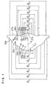
In drawings, FIG. 1 is a cross-sectional view
showing an Embodiment of the objective lens according to
the present invention;
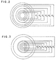
FIG. 2 is a front view of the objective lens shown
in FIG. 1 which is observed from a side of the light
source;
FIG. 3 is a rear view of the objective lens shown in
FIG. 1;
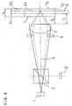
FIG. 4 is a diagram showing an Embodiment of the
optical device according to the present invention;
FIG. 5 is a diagram of an Embodiment of the optical
device which is different from that shown in FIG. 4;
FIG. 6 is a cross-sectional view showing an
objective lens according to Example 1;
FIG. 7 is a cross-sectional view showing an
objective lens according to Example 2;
FIG. 8 is a cross-sectional view showing an
objective lens according to Example 3;
FIG. 9 is an off-axial wavefront aberration
characteristic diagram of an optical system for CD in
Example 1;
FIG. 10 is an off-axial wavefront aberration
characteristic diagram of an optical system for DVD in
Example 1;
FIG. 11 is an off-axial wavefront aberration
characteristic diagram of an optical system for CD in
Example 2;
FIG. 12 is an off-axial wavefront aberration
characteristic diagram of an optical system for DVD in
Example 2;
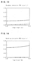
FIG. 13 is an off-axial wavefront aberration
characteristic diagram of an optical system for CD in
Example 3;
FIG. 14 is an off-axial wavefront aberration
characteristic diagram of an optical system for DVD in
Example 3;
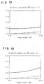
FIG. 15 is an off-axial wavefront aberration
characteristic diagram of an optical system for CD in
Example 4;
FIG. 16 is an off-axial wavefront aberration
characteristic diagram of an optical system for DVD in
Example 4;
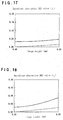
FIG. 17 is an off-axial wavefront aberration
characteristic diagram of an optical system for CD in
Example 5;
FIG. 18 is an off-axial wavefront aberration
characteristic diagram of an optical system for DVD in
Example 5;
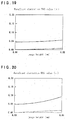
FIG. 19 is an off-axial wavefront aberration
characteristic diagram of an optical system for CD in
Example 6;
FIG. 20 is an off-axial wavefront aberration
characteristic diagram of an optical system for DVD in
Example 6;
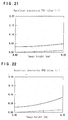
FIG. 21 is an off-axial wavefront aberration
characteristic diagram of an optical system for CD in
Example 7 and
FIG. 22 is an off-axial wavefront aberration
characteristic diagram of an optical system for DVD in
Example 7.
Preferred Embodiments of the objective lens and the
optical device of the present invention will be described
with reference to the drawings.
FIG. 1 is a cross-sectional view showing an
Embodiment of the objective lens of the present
invention, which is sectioned in parallel to and on the
optical axis 4, and is observed from a direction
perpendicular to the optical axis 4. Directions are
determined based on the surface of the papers on which
figures are drawn (when the A4 papers are observed in a
longitudinal direction, a left side corresponds to an
upper portion and a lower portion corresponds to a light
source side). FIG. 2 is a front view of the objective
lens shown in FIG. 1, observed from the light source
side, and FIG. 3 is a rear view with respect to FIG. 2.
In FIG. 1, reference numerals 11, 12, 13, 14 and 15
designate ring-like step portions having the center
coincident with the optical axis; numerals 21, 22, 23,
24, 25 and 26 designate ring-like step portions having
the center coincident with the optical axis 4; characters
11, 12, 13, 14 and 15 designate respectively the
diameter of an inner side of the step portions 11, 12,
13, 14 and 15; 16 designates an effective diameter of
the first surface; 21, 22, 23, 24, 25 and 26
designate respectively the diameter of an inner side of
the step portions 21, 22, 23, 24, 25 and 26, and 27
designates an effective diameter of the second surface.
The angle of each step portion is not limited to a right
angle but it may have an angle gently inclined. In the
following description, dimensions such as distance,
interval, length, thickness and so on are expressed by a
unit of mm unless specifically described.
The objective lens of the present invention is used
for an optical system in which light from one or two
light sources having different wavelengths with respect
to two optical disks is converged to respective data
recording surfaces of the optical disks and reflected
light from the respective recording surfaces is received
by a light receiving element in recording or reading the
optical disks. The objective lens of the present
invention has aspheric surfaces in both surfaces.
When the first optical disk is recorded or read, the
first wavelength is used, and when the second optical
disk is recorded or read, the second wavelength is used.
In a surface of the objective lens, the first phase
shifter provided with, for example, the ring-like step
portions 11, 12, 13, 14 and 15 having the center
coincident with the optical axis is provided. The first
phase shifter has function to produce a phase difference
with respect to the light having the first wavelength
(i.e., to shift the phase of the light having the first
wavelength). By shifting the phase of the light having
the first wavelength, the aberration, in particular, the
on-axial spherical aberration is improved in recording or
reading the first optical disk.
In the other surface of the objective lens, the
second phase shifter provided with, for example, the
ring-like step portions 21, 22, 23, 24, 25 and 26 having
the center coincident with the optical axis is provided.
The second phase shifter has function to produce a phase
difference with respect to the light having the second
wavelength (i.e., to shift the phase of the light having
the second wavelength). By shifting the phase of the
light having the second wavelength, the aberration, in
particular, the on-axial spherical operation is improved
in recording or reading the second optical disk. The
number of the step portions is not limited to that shown
in FIG. 1 but the change is optional.
It is possible that the first phase shifter is
provided in the first surface (the surface at a light
source side) of the objective lens, and the second phase
shifter is provided in the second surface (the surface at
an optical disk side) of the objective lens. Or, it is
possible that the first phase shifter is provided in the
second surface of the objective lens, and the second
phase shifter is provided in the first surface of the
objective lens. The step portions for forming the first
phase shifter or the second phase shifter may comprise
convex portions or concave portions provided in the
surfaces of the objective lens.
In order to shift the phase of the light having the
first wavelength, it is preferable that the dimensions
and the shape of the step portions of the first phase
shifter is determined so that a phase difference caused
by the light having the first wavelength is i times of
0.9λ2 to 1.1λ2 where λ2 represents the second wavelength
and i represents a natural number, when it is converted
into a distance.
In order to shift the phase of the light having the
first wavelength, it is more preferable that the
dimensions and the shape of the step portions of the
first phase shifter are determined so that a phase
difference caused by the light having the first
wavelength is in a range of from (i-0.1)λ2 to (i+0.1)λ2
when it is converted into a distance.
In order that the phase difference caused by the
light having the first wavelength is i times of 0.9λ2 to
1.1λ2, the head γ1 of each ring-like step portion of the
first phase shifter, λ2 and the refractive index n2 of a
material for the objective lens 3 to the second
wavelength satisfy the following Formula 1.
0.9iλ2/(n2-1)≦λ1≦1.1iλ2/(n2-1)
In order that the phase difference caused by the
light having the first wavelength is in a range of from
(i-0.1) λ2 to (i+0.1) λ2, it is necessary to satisfy the
following Formula 2.
(i-0.1)λ2/(n2-1)≦γ1≦(i+0.1)λ2/(n2-1)
Here, in a case that each aspheric surface having a
ring-like shape is provided between the ring of a step
portion and the ring of another step portion, or in the
vicinity of the effective diameter (hereinbelow, referred
to as each ringed belt-like aspheric surface or ringed
belt-like aspheric surfaces), a head means a distance
between the crossing point of an extension from a ringed
belt-like aspheric surface toward the optical axis 4
according to Formula 5 described after and the optical
axis 4 and the apex of the surface of the objective lens
in which the ringed belt-like aspheric surface is
provided. For example, there is a distance γ11 (the head
of the step portion 11) in FIG. 1. This distance is
along the optical axis 4. The way of thinking of the
head is also applicable to Formulae 3 and 4 described
after.
Further, in order to shift the phase of the light
having the second wavelength, it is preferable that the
dimensions and the shape of the step portions of the
second phase shifter are determined so that a phase
difference caused by the light having the second
wavelength is j times of 0.9λ1 to 1.1λ1 where λ1
represents the first wavelength and j represents a
natural number when it is converted into a distance.
In order to shift the phase of the light having the
second wavelength, it is more preferable that the
dimensions and the shape of the step portions of the
second phase shifter are determined so that a phase
difference caused by the light having the second
wavelength λ2 is in a range of from (j-0.1) λ1 to
(j+0.1)λ1 when it is converted into a distance.
In order that the phase difference caused by the
light having the second wavelength is j times of 0.9λ1
to 1.1λ1, the head γ2 of each ringed belt-like step
portion of the second phase shifter, λ1 and the
refractive index n1 of a material for the objective lens
should satisfy the following Formula 3.
0.9jλ1/(n1-1)≦γ2≦1.1jλ1/(n1-1)
In order that the phase difference caused by the
light having the second wavelength λ2 is in a range of
from (j-0.1)λ1 to (j+0.1)λ1 when it is converted into a
distance, the head γ2 of each ringed belt-like step
portion of the second phase shifter, λ1 and the
refractive index n1 of a material for the objective lens
should satisfy the following Formula 4.
(j-0.1)λ1/(n1-1)≦γ2≦(j+0.1)λ1/(n1-1)
When a numerical aperture NA1 of the objective lens
in recording or reading the first optical disk and a
numerical aperture NA2 of the objective lens in recording
or reading the second optical disk satisfy NA1>NA2, it is
preferable that an inner diameter 1 of the step portion
having the smallest diameter among the step portions of
the first phase shifter, an effective diameter A of the
surface of the objective lens in which the first phase
shifter is provided (corresponding to 16 in FIG. 1), an
inner diameter 2 of the step portion having the
smallest diameter among the step portions of the second
phase shifter, and an effective diameter B of the
surface of the objective lens in which the first phase
shifter is provided (corresponding to 27 in FIG. 1),
satisfy 1/A>2/B.
It is because correction of the aberration has to be
conducted to the second phase shifter in a range of NA2
having a smaller numerical aperture. When 11/A/2/B
is not satisfied, recording or reading to the second
optical disk may not be performed well. By the same
reason, it is preferable to satisfy 1/A/2/B when
NA1>1.2NA2 is established.
It is preferable that in establishment of 1.5t1<t2,
the total number of rings of the step portions of the
first phase shifter is 3 - 10, and the total number of
the rings of the step portions of the second phase
shifter is 3 - 10. When the total number is respectively
3 or less, the on-axial spherical aberration may not be
corrected well. Further, in consideration that the
effective diameters of the first and second surfaces of
the objective lens are generally 5.0 mm or less, the
rings of the step portions exceeding 10 may cause
difficulty in manufacturing. Preferably, the total
number of the rings of the step portions of the first
phase shifter is 4 - 8, and the total number of the rings
of the step portions of the second phase shifter is 5-8.
FIG. 4 is a diagram showing an embodiment of the
optical device according to the present invention. In
FIG. 4, reference numeral 1 designates a light source,
numeral 2 designates an optical medium having a
reflecting function, numeral 3 an objective lens, numeral
5 an auxiliary lens, numeral 6 a first optical disk,
numeral 6a a transparent substrate of the first optical
disk 6 (hereinbelow, referred to as a first transparent
substrate), numeral 6b a data recording surface of the
first optical disk 6 (hereinbelow referred to as a first
data recording surface), numeral 7 a second optical disk,
numeral 7a a transparent substrate of the second optical
disk 7 (hereinbelow, referred to as a second transparent
substrate), numeral 7b a data recording surface of the
second optical disk 7 (hereinbelow, referred to as a
second data recording surface), numeral 9 an aperture,
numeral 10 a light receiving element, character S1 the
distance on the optical axis from the light source 1 to
the surface (the first surface) at a light source side of
the auxiliary lens 5, and character S2 the distance on
the optical axis from the surface (the second surface) at
an optical disk side of the auxiliary lens 5 to the first
surface of the objective lens 3.
In the optical device shown in FIG. 4, the numerical
aperture NA1 of the objective lens 3 in recording or
reading the first optical disk by using the first
wavelength and the numerical aperture NA2 of the
objective lens 3 in recording or reading the second
optical disk by using the second wavelength satisfy
NA1>NA2.
FIG. 5 is a diagram showing an embodiment different
from that shown in FIG. 4. In the optical device shown
in FIG. 5, light from the light source 1 is converged to
the data recording surface of the optical disk by only
the objective lens 3.
In FIG. 4, light having the first wavelength emitted
from the light source 1 is successively passed through
the optical medium 2, the auxiliary lens 5 and the
objective lens 3 to be introduced into and converged on
the first data recording surface 6b. In FIG. 5, since
the auxiliary lens 5 is not provided, light having the
first wavelength is successively passed through the
optical medium 2 and the objective lens 3 to be
introduced into and converged on the first data recording
surface 6b.
In FIG. 4, light having the second wavelength
emitted from the light source 1 is successively passed
through the optical medium 2, the auxiliary lens 5 and
the objective lens 3 to be introduced into and converged
on the second data recording surface 7b. In FIG. 5,
since the auxiliary lens 5 is not provided, light having
the first wavelength is successively passed through the
optical medium 2 and the objective lens 3 to be
introduced into and converged on the second data
recording surface 7b.
The light having the first wavelength reflected by
the first data recording surface 6b and the light having
the second wavelength reflected by the second data
recording surface 7b are returned on the light paths
along which they come and are reflected by the optical
medium 2 to be received by the light receiving element
10.
The optical systems of the optical devices shown in
FIGS. 4 and 5 form finite type optical systems in their
entirety. The objective lens 3 in FIG. 4 may be an
infinite type lens when the auxiliary lens is a
collimeter lens. The objective lens in FIG. 5 is a
finite type lens. It is because light from the light
source located in a range of finite distance with respect
to an optical disk is converged to the data recording
surface of the optical disk. The objective lens 3
includes an objective lens designed as an infinite type
which is usable as a finite type even in a case that a
finite type lens can be used.
Further, marks representing digital signals are
recorded in the first data recording surface 6b and the
second data recording surface 7b. When the dimension of
1 pit for each mark is several µm or less, the optical
system of the optical device of the present invention has
a diffraction-limited performance in order to achieve
precise recording or reading.
As the light source 1, a laser light source or the
like may be mentioned, for example. Assumed that the
first optical disk 6 is DVD and the second optical disk 7
is CDs, a laser light source having a wavelength of 780
nm may be used for CD and a laser light source having a
wavelength 650 nm may be used for DVD, for example.
However, the wavelengths of the light sources are not
limited to the above-mentioned 650 nm and 780 nm.
In the optical device shown in FIG. 4, a combination
of the auxiliary lens 5 and the objective lens 3 is
optimized with respect to the thickness t1 of the first
transparent substrate 6a so that the light having the
first wavelength is well converged on the data recording
surface 6b, and a combination of the auxiliary lens 5 and
the objective lens 3 is optimized with respect to the
thickness t2 of the second transparent substrate 7a so
that the light having the second wavelength is well
converged on the second data recording surface 7b.
In other words, in the combination of the auxiliary
lens 5 and the objective lens 3 in FIG. 4, correction of
the aberration is properly carried out with respect to
the first wavelength, the object-image distance and the
thickness t1 of the first transparent substrate 6a, and
the aberration characteristics of the optical system for
recording or reading the first optical disk 6 by using
the light having the first wavelength are optimized
either in off-axial or on-axial. Further, in the
combination of the auxiliary lens 5 and the objective
lens 3 in FIG. 4, correction of the aberration is
properly carried out with respect to the second
wavelength, the object-image distance and the thickness
t2 of the second transparent substrate 7a, and the
aberration characteristics of the optical system for
recording or reading the second optical disk 7 by using
the light having the second wavelength are optimized
either in off-axial or on-axial. The auxiliary lens 5 is
so determined that the aberration becomes optimum when
used in combination with the objective lens 3.
In the optical device shown in FIG. 5, the objective
lens 3 is optimized with respect to the thickness t1 of
the first transparent substrate 6a so that the light
having the first wavelength is well converged on the
first data recording surface 6b, and the objective lens 3
is optimized with respect to the thickness t2 of the
second transparent substrate 7a so that the light having
the second wavelength is well converged on the second
data recording surface 7b.
In other words, in the objective lens 3 in FIG. 5,
correction of the aberration is properly carried out with
respect to the first wavelength, the object-image
distance and the thickness t1 of the first transparent
substrate 6a, and the aberration characteristics of the
optical system for recording or reading the first optical
disk 6 by using the light having the first wavelength are
optimized either in off-axial or on-axial. Further, in
the objective lens 3 in FIG. 5, correction of the
aberration is properly carried out with respect to the
second wavelength, the object-image distance and the
thickness t2 of the second transparent substrate 7a, and
the aberration characteristics of the optical system for
recording or reading the second optical disk 7 by using
the light having the second wavelength are optimized
either in off-axial or on-axial. Thus, the recording or
reading of the first optical disk 6 and the second
optical disk 7 which differ in the thickness of their
transparent substrates are well carried out. Further,
the aberration characteristics are influenced by not only
the thickness of the transparent substrates, but also the
refractive index of the transparent substrates although
the degree of influence is slight.
In the optical device shown in FIG. 4, it is
preferable that a combination of an aspheric surface in
the surface including the apex in a surface of the
objective lens 3 (for instance, the aspheric surface 11a)
and an aspheric surface in the surface including the apex
in the other surface of the objective lens 3 (for
instance, the aspheric surface 21a) and the optical
system comprising the auxiliary lens 5, with respect to
the light having the first wavelength, is so determined
that the off-axial coma aberration in an image height of
0.05 mm is 0.03 λ1 or less in RMS value when data in the
data recording surface 6b of the first optical disk 6 are
recorded or read, and a combination of an aspheric
surface in the surface including the apex in the surface
of the objective lens 3 (for instance, the aspheric
surface 11a) and an aspheric surface in the surface
including the apex in the other surface of the objective
lens 3 (for instance, the aspheric surface 21a) and the
optical system comprising the auxiliary lens 5, with
respect to the light having the second wavelength, are so
determined that the off-axial coma aberration in an image
height of 0.05 mm is 0.03 λ2 or less in RMS value when
data in the data recording surface 7b of the second
optical disk 7 are recorded or read.
In the optical device shown in FIG. 4, it is more
preferable that a combination of each ringed belt-like
aspheric surface in a surface of the objective lens 3
(for instance, the ringed belt-like aspheric surface 12a,
13a, 14a, 15a, 16a) and an aspheric surface in the
surface including the apex in the other surface of the
objective lens 3 (for instance, the aspheric surface 21a)
and the optical system comprising the auxiliary lens 5,
with respect to the light having the first wavelength,
are so determined that the off-axial coma aberration in
an image height of 0.05 mm is 0.03 λ1 or less in RMS
value when data in the data recording surface 6b of the
first optical disk 6 are recorded or read, and a
combination of an aspheric surface in the surface
including the apex in the surface of the objective lens 3
(for instance, the aspheric surface 11a) and each ringed
belt-like aspheric surface in the other surface of the
objective lens 3 (for instance, the ringed belt-like
aspheric surface 22a, 23a, 24a, 25a, 26a, 27a) and the
optical system comprising the auxiliary lens 5, with
respect to the light having the second wavelength are so
determined that the off-axial coma aberration in an image
height of 0.05 mm is 0.03 λ2 or less in RMS value when
data in the data recording surface 7b in the second
optical disk 7 are recorded or read.
In the optical device shown in FIG. 5, it is
preferable that a combination of an aspheric surface in
the surface including the apex in a surface of the
objective lens 3 (for instance, the aspheric surface 11a)
and an aspheric surface in the surface including the apex
in the other surface of the objective lens 3 (for
instance, the aspheric surface 21a) with respect to the
light having the first wavelength is so determined that
the off-axial coma aberration in an image height of 0.05
mm is 0.03 λ1 or less in RMS value when data in the data
recording surface 6b of the first optical disk 6 are
recorded or read, and a combination of an aspheric
surface in the surface including the apex in the surface
of the objective lens 3 (for instance, the aspheric
surface 11a) and an aspheric surface in the surface
including the apex in the other surface of the objective
lens 3 (for instance, the aspheric surface 21a) is so
determined that the off-axial coma aberration in an image
height of 0.05 mm is 0.03 λ2 or less in RMS value when
data in the data recording surface 7b of the second
optical disk 7 are recorded or read.
In the optical device shown in FIG. 5, it is more
preferable that a combination of each ringed belt-like
aspheric surface in the surface of the objective lens 3
(for instance, the ringed belt-like aspheric surfaces
12a, 13a, 14a, 15a, 16a) and an aspheric surface in the
surface including the apex in the other surface of the
objective lens 3 (for instance, the aspheric surface 21a)
with respect to the light having the first wavelength is
so determined that the off-axial coma aberration in an
image height of 0.05 mm is 0.03 λ1 or less in RMS value
when data in the data recording surface 6b of the first
optical disk 6 are recorded or read, and a combination of
an aspheric surface in the surface including the apex in
the surface of the objective lens 3 (for instance, the
aspheric surface 11a) and each ringed belt-like aspheric
surface in the other surface of the objective lens 3 (for
instance, the ringed belt-like aspheric surfaces 22a,
23a, 24a, 25a, 26a, 27a) with respect to the light having
the second wavelength is so determined that the off-axial
coma aberration in an image height of 0.05 mm is 0.03 λ2
or less in RMS value when data in the data recording
surface 7b of the second optical disk 7 are recorded or
read.
When the off-axial coma aberration in an image
height of 0.05 mm is 0.03 λ or less, an allowable range
in an inclination or a shift of axis from the optical
axis of the light source, the auxiliary lens, the object
lens or the optical disk is expanded to 0.1% or more in
comparison with the case that the off-axial coma
aberration is more than 0.03 λ. A more preferable range
of the off-axial coma aberration in an image height of
0.05 mm is 0.01 λ or less. In this case, an allowable
range is expanded to 0.5% or more in comparison with the
case that the off-axial coma aberration is more than 0.01
λ.
When the lateral magnification in combination of the
auxiliary lens 5 and the objective lens 3 which
corresponds to a combination of the light having the
first wavelength and the first transparent substrate 6a
in the optical device shown in FIG. 4 is indicated by β
1, the lateral magnification of the objective lens 3 in
combination which corresponds to a combination of the
light having the first wavelength and the first
transparent substrate 6a in the optical device shown in
FIG. 5 is also indicated by β1, the lateral
magnification in combination of the auxiliary lens 5 and
the objective lens 3 which corresponds to a combination
of the light having the second wavelength and the second
transparent substrate 7a in the optical device shown in
FIG. 4 is indicated by β2, and the lateral magnification
of the objective lens 3 in combination which corresponds
to a combination of the light having the second
wavelength and the second transparent substrate 7a in the
optical device shown in FIG. 5 is also indicated by β2,
it is preferable that both conditions described in the
following Formulae (A) and (B) are satisfied.
(A) 0.05 ≦ |β1 |≦0.3,
and
(B) 0.05 ≦ |β2 | ≦ 0.3
In a case that 0.05≦|β1| and 0 . 05 ≦ |β2| are not
satisfied, the object-image distance becomes too long so
that miniaturization of the optical device becomes
difficult. Further, in a case that |β1|≦0.3 and
|β2|≦0.3 are not satisfied, correction of the aberration
becomes difficult.
Further, in the optical device shown in FIG. 4, it is
preferable that the distance S1 on the optical axis from
the light source 1 to the surface, at a side of the light
source 1, of the auxiliary lens 5 is 8 mm≦S1≦25 mm.
When S1 is less than 8 mm, correction of the aberration
becomes difficult. On the other hand, when S1 exceeds 25
mm, miniaturization of the optical device becomes
difficult.
As an example of the optical medium 2, there are a
beam splitter, half mirror, prism and so on, for example.
In the optical device shown in FIGS. 4 and 5, the optical
medium 2 may not be provided so that light from the light
source 1 is incident directly to the objective lens 3.
Further, means for supplying data in the data
recording surface of the optical disk to the light
receiving element are not limited to those as shown in
FIGS. 4 and 5.
The aperture 9 functions to change a numerical
aperture (NA). The reason why the aperture 9 is provided
is that when a numerical aperture used for the first
optical disk 6 is different from a numerical aperture for
the second optical disk 7 in recording or reading, the
numerical apertures have to be adjusted by the aperture
10. When a numerical aperture used for the first optical
disk 6 is the same as a numerical aperture for the second
optical disk 7, the aperture 9 is generally unnecessary.
As the aperture 9, there are a mechanical aperture and an
optical aperture, which is however, not limited thereto.
When Na1>Na2 is established between a numerical
aperture NA1 of the objective lens used for the first
optical disk and a numerical aperture NA2 of the
objective lens used for the second optical disk, a step
portion may be provided, instead of the aperture 9, in a
ringed belt-like region having the center coincident with
the optical axis, in a or both surfaces of the objective
lens to prevent the light having the second wavelength
from passing through to thereby throttle the light to the
numerical aperture NA2.
In FIG. 4, the auxiliary lens 5 is constituted by a
single lens. However, the auxiliary lens 5 is not
limited to have such structure, and it may comprise a
plurality of lenses.
In the above, description has been made as to
recording or reading two kinds of optical disk. However,
the present invention is not limited thereto and
recording or reading can be conducted to three or more
kinds of optical disk wherein the thickness of these
transparent substrates are all different. Further, the
optical disks used in the present invention are not
limited to DVD or CD but may be another kind of optical
disk.
In the optical device shown in FIG. 4 and 5, light
having the first wavelength and light having the second
wavelength are emitted from a single light source 1.
However, the present invention is not limited thereto and
light sources for emitting the light having the first
wavelength and the light having the second wavelength may
be provided separately.
Generally, a synthetic resin is used as materials
for the auxiliary lens 5 and the objective lens 4. The
materials are not limited to synthetic resin, and glass
may be used. Further, an autofocusing driving means may
be provided for the objective lens in the optical device
of the present invention.
Now, the present invention will be described in
detail with reference to Examples. However, it should be
understood that the present invention is by no means
restricted by such specific examples.
EXAMPLE
An optical device as shown in FIG. 4 was prepared on
the premise of recording or reading CD and DVD wherein
DVD (t1=0.60 mm) was used as the first optical disk 6 and
CD (t2=1.20 mm) was used as the second optical disk 7.
A laser light source for emitting light having a
wavelength of 650 nm was used for reading or recording
DVD and a laser light source for emitting light having a
wavelength of 780 nm was used for reading or recording
CD. As the optical medium 2, a beam splitter made of a
material of BK and having a thickness 3.00 mm was used.
The transparent substrate of DVD was designed to have a
refractive index of 1.580 with the wavelength of 650 nm.
The transparent substrate of CD was designed to have a
refractive index of 1.573 with the wavelength of 780 nm.
The shape of the aspheric surfaces formed in the
objective lens 3 including each ringed belt-like aspheric
surface was determined according to the following Formula
5. In Formula 5, i is 2, 4, 6, 8 or 10; j is 1 or 2; h
is a height from the optical axis; zj is a distance from
a surface contact with the apex of the j th aspheric
surface to a point having a height h on the aspheric
surface, and rj, kj, ai, j is the coefficient of the j th
surface respectively.
Zj=(1/rj)h2/[1+{1-(1+kj)(1/rj)2h2}0.5]+Σiai,jhi
EXAMPLE 1 (COMPARATIVE EXAMPLE)
The shape of the objective lens 3 was such shape as
shown in FIG. 6. For either CD or DVD, designing was
conducted so that the on-axial spherical aberration was
not corrected but the off-axial coma aberration was well
corrected.
Specifications and numerical values of the optical
device and the objective lens in Example 1 are shown in
the first left and right frames of Table 1. In the first
left and right frames of Table 1, f
1 indicates the focal
distance of the objective lens 3 at a wavelength of 650
nm, f
2 indicates the focal distance of the objective lens
3 at a wavelength of 780 nm, d
1 indicates the thickness
of the center of the objective lens 3, n
1 indicates the
refractive index of the objective lens 3 at a wavelength
of 650 nm, and n
2 indicates a refractive index of the
objective lens 3 at a wavelength of 780 nm. Coefficients
of the aspheric surface in the first surface of the
objective lens in Example 1 are shown in the second left
and right frames of Table 1, and coefficients of the
aspheric surface in the second surface of the objective
lens are shown in the third left and right frames of
Table 1. In Tables described Hereinbelow, E-1 means 10
-1.
| f 1 = 3. 0 1 2 mm | d 1 = 2. 0 0 mm |
| f 2 = 3. 0 2 9 mm | n 1=1. 5 4 0 7 |
| NA1 = 0. 6 5 0 | n 2= 1. 5 3 7 3 |
| NA2=0. 5 2 0 |
| r 1 = 1. 1 8 7 7 7 2 | a 2, 1=-1. 6 5 2 3 5 1 4 E- 1 |
| k 1=-1. 0 2 1 7 6 4 | a 4, 1= 1. 0 6 0 9 3 1 E - 2 |
| | a 6, 1= 2. 2 7 5 2 5 2 5 E - 3 |
| | a 8, 1=-2. 8 0 9 9 6 4 5 E - 4 |
| r 2=-5. 802628 | a 2,2= 6. 0824628E-3 |
| k 2 = - 1 0 | a 4,2= 2. 9 5 5 1 1 5 6 E - 2 |
| | a 6, 2 = - 8. 9 4 2 3 5 3 E - 3 |
| | a 8, 2 = 9. 3 1 5 9 9 4 4 E - 4 |
A collimater lens was used as the auxiliary lens and
the shape of the aspheric surface of the auxiliary lens
was determined according to Formula 5. Coefficients of
the aspheric surface of the auxiliary lens are shown in
upper frames of Table 2. In the upper frames of Table 2,
fc1 indicates the focal distance at a wavelength of 650
nm, fc2 indicates the focal distance at a wavelength of
780 nm dc indicates the thickness at the center, nc1
indicates the refractive index at a wavelength of 650 nm,
and nc2 indicates the refractive index at a wavelength of
780 nm. In Examples 2 - 5, the auxiliary lens as
indicated in the upper frames of Table 2 was also used.
Specifications of the auxiliary lens as in the upper
frames and the optical system comprising the objective
lens in Table 1 are indicated in lower frames of Table 2.
In the lower frames of Table 2, P
1 indicates the distance
(operating distance) between the second surface of the
objective lens and the surface at an objective lens side
of the first optical disk 6 at a wavelength of 650 nm,
and P
2 indicates the distance (operating distance)
between the second surface of the objective lens and the
surface at an objective lens side of the second optical
disk.
| fC1 = 1 8. 0 0 m m | r1 = 3 7. 0 5 0 9 2 |
| fC2= 1 8. 1 1 m m | r2=-1 2. 4 3 3 1 2 |
| dC=2. 4 5 m m | k1=1 9. 5 7 5 2 9 |
| nc1 = 1. 5 4 0 7 | k2=- 1. 0 0 7 7 2 2 |
| nc2 = 1. 5 3 7 3 | a2, 1=-2. 0 7 4 7 5 7 9 E - 3 |
| S1= 1 7. 7 5 m m | a2, 2=-5. 3 7 0 9 7 4 1 E - 4 |
| S2=5. 2 5 m m | a4, 1=8. 7 1 3 3 7 9 4 E - 5 |
| | a4, 2 =1. 2 1 5 6 9 1 E - 4 |
| | a6, 1=0. 0 |
| | a6, 2=0. 0 |
| | a8, 1=0. 0 |
| | a8, 2= 0. 0 |
| | Optical system | Optical system |
| | for CD | for DVD |
| Aperture (diameter) | 3. 1 6 mm | 3. 9 4 mm |
| Lateral magnification of | -0. 1 6 8 | -0. 1 6 7 |
| optical system (β1, β2) |
| P1, P2 | 1. 2 0 m m | 1. 5 5mm |
FIG. 9 shows the off-axial wavefront aberration
characteristics of the optical system for CD. In FIG. 9,
a solid line shows a wavefront aberration including all
kinds of aberration. A broken line shows only an off-axial
coma aberration in the off-axial wavefront
aberration. FIG. 10 shows the off-axial wavefront
aberration characteristics of the optical system for DVD.
The solid line and the broken line have the same meaning
as in FIG. 9. Further, in the aberration characteristic
diagrams described hereinbelow, solid lines and broken
lines have the same meaning as in FIG. 9. The aberration
characteristic diagrams on each Example and aberration
values in Tables described after one all based on
calculated values. The objective lens of Example 1 and
an auxiliary lens were prepared by injection-molding a
plastic material, and the optical device of FIG. 4 was
fabricated. When recording or reading was conducted to
DVD and CD with this optical device, accurate recording
or reading could not be performed for both DVD and CD.
EXAMPLE 2 (COMPARATIVE EXAMPLE)
An objective lens was formed to have such shape as
shown in FIG. 7 wherein specifications of the lens were
the same as those of Example 1 as described in the first
left and right frames of Table 1, which are basic
specifications. A first phase shifter was provided in a
first surface of the objective lens in order to correct
the on-axial spherical aberration for DVD. The shape of
the first surface of the objective lens was the same as
the first surface of the objective lens as shown in FIG.
1, and the second surface of the objective lens was the
same as the second surface of the objective lens of
Example 1. In the following, an aspheric surface in the
first surface of the objective lens will be described by
using the same reference numerals as in FIG. 1.
An aspheric surface 11a in the surface including the
apex in the first surface of the objective lens was
formed in the same manner as the aspheric surface in the
surface including the apex in the first surface of the
objective lens of Example 1. The second surface of the
objective lens 3 was formed in the same manner as the
second surface of the objective lens of Example 1.
Coefficients of aspheric surface of a ringed belt-like
aspheric surface 12a are shown in an upper column of
Table 3; coefficients of the aspheric surface of ringed
belt-like aspheric surfaces 13a, 15a are shown in a
middle column of Table 3, and coefficients of aspheric
surface of ringed belt-like aspheric surfaces 14a, 16a
are shown in a lower column of Table 3. Further, each
head γ
1 is described in an upper right column of Table
4. Further,
11,
12,
13,
14,
15 and
16 are shown in
a lower right column of Table 4.
| Head γ11 of ring-like step portion 11 | 1. 45 µm |
| Head γ12 of ring-like step portion 12 | 2. 90 µ m |
| Head γ13 of ring-like step portion 13 | 4. 3 5 µm |
| Head γ 14 of ring-like step portion 14 | 2. 9 0 µ m |
| Head γ15 of ring-like step portion 15 | 4. 3 5 µ m |
| 11 | 1. 1 0 mm |
| 12 | 1. 4 8 mm |
| 13 | 1. 9 2 mm |
| 14 | 2. 6 8 mm |
| 15 | 3. 5 0 mm |
| 16 | 3. 9 7 mm |
FIG. 11 shows the off-axial wavefront aberration
characteristics of the optical system for CD. FIG. 12
shows the off-axial wavefront aberration characteristics
of the optical system for DVD. The objective lens having
the shape as shown in Example 2 and the auxiliary lens 5
were prepared by injection-molding a plastic material,
and the optical device of FIG. 4 was fabricated. When
recording or reading was conducted to DVD and CD with
this optical device, accurate recording or reading could
not be performed for CD although accurate recording or
reading could be performed for DVD.
EXAMPLE 3 (COMPARATIVE EXAMPLE)
An objective lens was prepared to have such shape of
lens as shown in FIG. 8 wherein specifications of the
lens were the same as those of Example 1 described in the
first left and right frames of Table 1, which are basic
specification. A second phase shifter was provided in
the second surface of the objective lens in order to
correct the on-axial spherical aberration for CD. The
second surface of the objective lens was such shape as
that of the second surface of the objective lens shown in
FIG. 1, and the first surface of the objective lens was
formed in the same manner as the first surface in the
objective lens of Example 1. In the following, the
aspheric surface in the second surface of the objective
lens will be described by using the reference numerals as
in FIG. 1.
An aspheric surface 21a in the surface including the
apex in the second surface of the objective lens was
formed in the same manner as the aspheric surface in the
surface including the apex in the first surface of the
objective lens. An aspheric surface lla in the surface
including the apex in the first surface of the objective
lens was formed in the same manner as the aspheric
surface in the surface including the apex in the first
surface of the objective lens of Example 1.
Coefficients of aspheric surface of a ringed belt-like
aspheric surface 22a are shown in the upper left
frame of Table 5; coefficients of aspheric surface of the
ringed belt-like aspheric surfaces 23a, 27a are shown in
the upper right frame of Table 5; coefficients of
aspheric surface of ringed belt-like aspheric surfaces
24a, 26a are shown in the lower left frame of Table 5,
and coefficients of aspheric surface of a ringed belt-like
aspheric surface 25a are shown in a lower right
frame of Table 5.
Further, each head γ2 is shown in the upper right
column of Table 6, and
21,
22,
23,
24,
25 and
26
are shown in the lower right column of Table 6.
| r2=-6.2025351 | r2=-5.960583851 |
| k2=-10 | k2=-10 |
| a2,2=7.037623E-4 | a2,2=4.121361E-3 |
| a4,2=3.046768E-2 | a4,2=2.983039E-2 |
| a6,2=-9.073626E-3 | a6,2=-8.963419E-3 |
| a8,2= 9.416602E-4 | a8,2=9.314379E-4 |
| r2=-6.277223534 | r2 = -6.344678464 |
| k 2 = - 1 0 | k 2=-1 0 |
| a2,2=6.027714E-5 | a2,2=-6.281483E-4 |
| a4,2= 3.048556E-2 | a4,2= 3.055276E-2 |
| a 6, 2 = -9.050586E-3 | a 6, 2 = -9.04747E-3 |
| a 8, 2 = 9.75883E-4 | a 8, 2 = 9.362317E-4 |
| Head γ 2 1 of ring-like step portion 21 | 1. 2 0 µ m |
| Head γ 2 2 of ring-like step portion 22 | 2. 4 0 µ m |
| Head γ 2 3 of ring-like step portion 23 | 3. 6 1 µ m |
| Head γ 2 4 of ring-like step portion 24 | 4. 8 1 µ m |
| Head γ 2 5 of ring-like step portion 25 | 3. 6 1 µ m |
| Head γ 2 6 of ring-like step portion 26 | 2. 4 0 µ m |
| 21 | 0.46mm |
| 22 | 0.78mm |
| 23 | 1.13mm |
| 24 | 1.49mm |
| 25 | 2.17mm |
| 26 | 2.32mm |
| 27 | 3.56 mm |
FIG. 13 shows the off-axial wavefront aberration
characteristics of the optical system for CD. FIG. 14
shows the off-axial wavefront aberration characteristics
of the optical system for DVD. An objective lens having
the shape of Example 3 and an auxiliary lens were
prepared, and the optical device of FIG. 4 was
fabricated. When recording or reading was conducted to
DVD and CD with this optical device, accurate recording
or reading could not be performed for DVD although
accurate recording or reading could be performed for CD.
EXAMPLE 4 (EXAMPLE)
An objective lens was formed to have such shape of
lens as shown in FIG. 1 wherein specifications of the
lens were the same as those of Example 1 described in the
first left and right frames of Table 1, which are basic
specification. The first surface of the objective lens
was formed in the same manner as the first surface of the
objective lens in Example 2, and the second surface of
the objective lens was formed in the same manner as the
second surface of the objective lens in Example 3.
FIG. 15 shows the off-axial wavefront aberration
characteristics of the optical system for CD. FIG. 16
shows the off-axial wavefront aberration characteristics
of the optical device for DVD. An objective lens having
the same shape as in Example 4 and an auxiliary lens were
prepared and the optical device of FIG. 4 was fabricated.
When recording or reading was conducted to CD and DVD
with this optical device, accurate recording or reading
could be performed for both CD and DVD.
EXAMPLE 5 (EXAMPLE)
An objective lens having the shape as shown in FIG.
1 was designed wherein specifications of the objective
lens were the same as those in Example 1 described in the
first left and right frames of Table 1, which are the
basic specification.
Coefficients of aspheric surface of an aspheric
surface 11a are shown in an upper left frame of Table 7;
coefficients of aspheric surface of a ringed belt-like
aspheric surface 12a are shown in an upper right frame of
Table 7; coefficients of aspheric surface of a ringed
belt-like aspheric surface 13a are shown in a middle left
frame of Table 7; coefficients of aspheric surface of a
ringed belt-like aspheric surface 14a are shown in a
middle right frame of Table 7; coefficients of aspheric
surface of a ringed belt-like aspheric surface 15a are
shown in a lower left frame of Table 7, and coefficients
of aspheric surface of a ringed belt-like aspheric
surface 16a are shown in a lower right frame of Table 7
respectively.
| r1=1.186966 | r1=1.1869361 |
| k1=-1.021764 | k1=1.021764 |
| a2,1=-1.65039E-1 | a2,1=-1.6517677E-1 |
| a4,1=1.0967235E-2 | a4,1=1.0746695E-2 |
| a6,1=2.5768064E-3 | a6,1=2.2932601E-3 |
| a8,1=-1.2901136E-3 | a8,1=-6.6819358E-4 |
| r1=1.1872281 | r1=1.186582 |
| k1=-1.021764 | k1=-1.021764 |
| a2,1=-1.6521502E-1 | a2,1=-1.6544294E-1 |
| a4,1=1.0670918E-2 | a4,1=1.0632515E-2 |
| a6,1=2.3099968E-3 | a6,1=2.2738951E-3 |
| a8,1=-2.9605177E-4 | a8,1=-2.9516419E-4 |
| r1=1.1874106 | r1=1.1866318 |
| k1=-1.021764 | k1=-1.021764 |
| a2,1=1.6527676E-1 | a2,1=-1.6545995E-1 |
| a4,1=1.0623504E-2 | a4,1=1.0636869E-2 |
| a6,1=2.2839713E-3 | a6,1=2.2852066E-3 |
| a8,1=-2.797455E- | a8,1=-2.8267783E-4 |
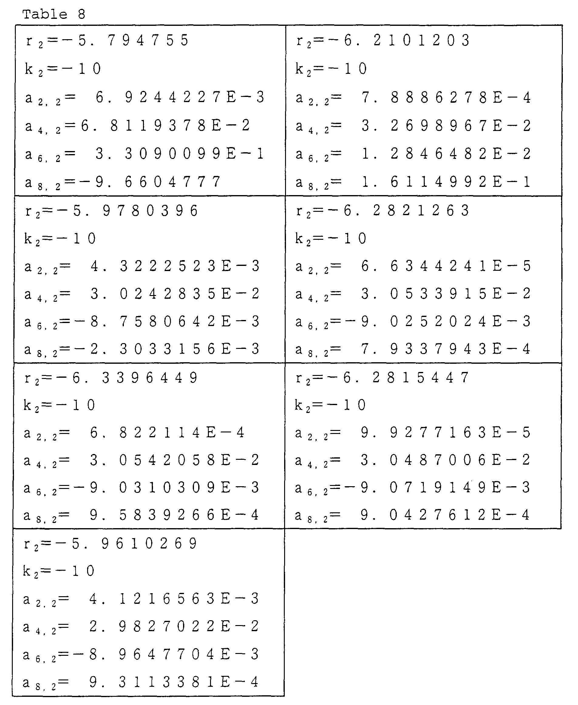
Coefficients of aspheric surface of a aspheric
surface 21a are shown in the first left frame of Table 8;
coefficients of aspheric surface of a ringed belt-like
aspheric surface 22a are shown in the first right frame
of Table 8; coefficients of aspheric surface of a ringed
belt-like aspheric surface 23a are shown in the second
left frame of Table 8; coefficients of aspheric surface
of a ringed belt-like aspheric surface 24a are shown in
the second right frame of Table 8; coefficients of
aspheric surface of a ringed belt-like aspheric surface
25a are shown in the third left frame of Table 8;
coefficients of aspheric surface of a ringed belt-like
aspheric surface 26a are shown in the third right frame
of Table 8, and coefficients of aspheric surface of a
ringed belt-like aspheric surface 2a are shown in the
fourth left frame of Table 8.
Specifications which are not described in Table 7
and Table 8 were determined in the same manner as in
Example 4. FIG. 17 shows the off-axial wavefront
aberration characteristics of the optical system for CD.
FIG. 18 shows the off-axial wavefront aberration
characteristics of the optical system for DVD. An
objective lens having the same shape as in Example 5 and
an auxiliary lens were prepared, and the optical device
of FIG. 4 was fabricated. When recording or reading was
conducted to CD and DVD with this optical device,
accurate recording or reading could be performed for both
CD and DVD.
EXAMPLE 6 (EXAMPLE)
An objective lens used for the optical device (of a
finite type) shown in FIG. 5 was designed wherein 7
ringed belt-like aspheric surfaces were formed in the
plane at a side of the light source, and 6 ringed belt-like
aspheric surfaces were formed in the surface at a
side of the optical disks.
The objective lens was designed so that the off-axial
coma aberration was excellent for either CD or DVD.
The 7 ringed belt-like aspheric surfaces formed in the
first surface were for phase correction for CD so that
the on-axial characteristics were corrected, and the 6
ringed belt-like aspheric surfaces formed in the second
surface were for correcting the on-axial spherical
aberration for DVD. Table 9 shows basic specifications
of the objective lens. Specifications such as wavelength
which are not described in Table 9 are the same as in
Example 4.
When an aspheric surface in the surface including
the apex in the surface, at a side of the light source,
of the objective lens 3 is referred to as a light source
side apex aspheric surface; a ringed belt-like aspheric
surface nearest to the light source side apex aspheric
surface is referred to as a first light source side
ringed belt-like aspheric surface, and ringed belt-like
aspheric surfaces formed successively from the first
light source side ringed belt-like aspheric surface
toward an outer periphery of the objective lens are
referred to a second light source side ringed belt-like
aspheric surface, a third light source side ringed belt-like
aspheric surface, ... respectively, coefficients of
aspheric surface of the light source side apex aspheric
surface are shown in the first left frame of Table 10;
coefficients of aspheric surface of the first light
source side ringed belt-like aspheric surface are shown
in the first right frame of Table 10; coefficients of
aspheric surface of the second light source side ringed
belt-like aspheric surface are shown in the second left
frame of Table 10; coefficients of aspheric surface of
the third light source side ringed belt-like aspheric
surface 24a are shown in the second light frame of Table
10; coefficients of aspheric surface of the fourth light
source side ringed belt-like aspheric surface 25a are
shown in the third left frame of Table 10; coefficients
of aspheric surface of the fifth light source side ringed
belt-like aspheric surface 26a are shown in the third
right frame of Table 10, and coefficients of aspheric
surface of the sixth light source side ringed belt-like
aspheric surfaces 2a are shown in the fourth left frame
of Table 10 respectively.
| r1=1.233515 | r1=1.1634129 |
| k1=-1.0 | k1=-1.0 |
| a2,1=-1.3150492E-1 | a2,1=-1.558908E-1 |
| a4,1=7.2179622E-3 | a4,1=7.225168E-3 |
| a6,1=2.3729098E-3 | a6,1=2.374128E-3 |
| a8,1=-4.934695E-4 | a8,1=-4.940307E-4 |
| r1=1.1698054 | r1=1.164662 |
| k1=-1.0 | k1=-1.0 |
| a2,1=-1.535026E-1 | a2,1=-1.553506E-1 |
| a4,1=7.231035E-3 | a4,1=7.236925E-3 |
| a6,1=2.375854E-3 | a6,1=2.377573E-3 |
| a8,1=-4.946562E-4 | a8,1=-4.952812E-4 |
| r1=1.1626195 | r1=1.164662 |
| k1=-1.0 | k1=-1.0 |
| a2,1=-1.560651E-1 | a2,1=-1.553506E-1 |
| a4,1=7.242843E-3 | a4,1=7.236925E-3 |
| a6,1=2.379282E-3 | a6,1=2.377573E-3 |
| a8,1=-4.959056E-4 | a8,1=-4.952812E-4 |
| r1=1.1698054 |
| k1=-1.0 |
| a2,1=-1.535026E-1 |
| a4,1=7.231035E-3 |
| a6,1=2.375854E-3 |
| a8,1=-4.946562E-4 |
When an aspheric surface in the surface including
the apex in the surface, at a side of the optical disks,
of the objective lens 3 is referred to as an optical disk
side apex aspheric surface; a ringed belt-like aspheric
surface nearest to the optical disk side apex aspheric
surface is referred to as a first optical disk side
ringed belt-like aspheric surface, and ringed belt-like
aspheric surfaces formed successively from the first
optical disk side ringed belt-like aspheric surface
toward an outer periphery of the objective lens are
referred to as a second optical disk side ringed belt-like
aspheric surface, a third optical disk side ringed
belt-like aspheric surface, ... respectively,
coefficients of aspheric surface of the optical disk side
apex aspheric surfaces are shown in the first left frame
of Table 11; coefficients of aspheric surface of the
first optical disk side ringed belt-like aspheric surface
are shown in the first right frame of Table 11;
coefficients of aspheric surface of the second optical
disk side ringed belt-like aspheric surfaces are shown in
the second left frame of Table 11; coefficients of
aspheric surface of the third optical disk side ringed
belt-like aspheric surfaces 24a are shown in the second
right frame of Table 11; coefficients of aspheric surface
of the fourth optical disk side ringed belt-like aspheric
surface 25a are shown in the third left frame of Table 11,
and coefficients of aspheric surface of the fifth optical
disk side ringed belt-like aspheric surface 26a are shown
in the third right frame of Table 11.
| r2=-3.340008 | r2=-3.3432047 |
| k2=-10 | k2=-10 |
| a2,2=7.015422E-3 | a2,2=7.111702E-3 |
| a4,2=2.0917566E-2 | a4,2=2.086996E-2 |
| a6,2=-6.8247138E-3 | a6,2=-6.807255E-3 |
| a8,2=6.74139E-4 | a8,2=6.718432E-4 |
| r2=-3.3478395 | r2=-3.3524715 |
| k2=-10 | k2=-10 |
| a2,2=7.145621E-3 | a2,2=7.17975E-3 |
| a4,2=2.085166E-2 | a4,2=2.083321E-2 |
| a6,2=-6.798639E-3 | a6,2=-6.789984E-3 |
| a8,2=6.706505E-4 | a8,2=6.694536E-4 |
| r2=-3.3478395 | r2=-3.35624715 |
| k2=-10 | k2=-10 |
| a2,2=7.145621E-3 | a2,2=7.17975E-3 |
| a4,2=2.085166E-2 | a4,2=2.083321E-2 |
| a6,2=-6.798639E-3 | a6,2=-6.789984E-3 |
| a8,2=6.706505E-4 | a8,2=6.694536E-4 |
Table 12 shows each head formed in the surface at a
light source side of the objective lens 3. In Table 12,
each light source side ringed belt-like aspheric surface
is provided at an optical disk side with respect to the
apex at a light source side.
| Head of the step portion between light source side apex aspheric surface and first light source side ringed belt-like aspheric surface | 1. 2 0 µ m |
| Head of the step portion between first light source side ringed belt-like aspheric surface and second light source side ringed belt-like aspheric surface | 2. 4 0 µ m |
| Head of the step portion between second light source side ringed belt-like aspheric surface and third light source side ringed belt-like aspheric surface | 3. 6 0 µ m |
| Head of the step portion between third light source side ringed belt-like aspheric surface and fourth light source side ringed belt-like aspheric surface | 4. 80 µm |
| Head of the step portion between fourth light source side ringed belt-like aspheric surface and fifth light source side ringed belt-like aspheric surface | 3. 60 µm |
| Head of the step portion between fifth light source side ringed belt-like aspheric surface and sixth light source side ringed belt-like aspheric surface | 2. 4 0 µ m |
Table 13 shows each head in the surface at a disk
side of the objective lens 3. In Table 13, each disk
side ringed belt-like aspheric surface is provided at a
light source side with respect to the apex at a disk side.
| Head of the step portion between disk side apex aspheric surface and first disk side ringed belt-like aspheric surface | 1. 4 5 µ m |
| Head of the step portion between first disk side ringed belt-like aspheric surface and second disk side ringed belt-like aspheric surface | 2. 9 0 µ m |
| Head of the step portion between second disk side ringed belt-like aspheric surface and third disk side ringed belt-like aspheric surface | 4. 3 5 µ m |
| Head of the step portion between third disk side ringed belt-like aspheric surface and fourth disk side ringed belt-like aspheric surface | 2. 9 0 µ m |
| Head of the step portion between fourth disk side ringed belt-like aspheric surface and fifth disk side ringed belt-like aspheric surface | 4. 3 5 µm |
Table 14 shows an outer diameter of each aspheric
surface of the objective lens 3.
| Outer diameter of light source side apex aspheric surface | 0. 6 9 6 |
| Outer diameter of first light source side ringed belt-like aspheric surface | 1. 1 2 0 |
| Outer diameter of second light source side ringed belt-like aspheric surface | 1. 5 8 4 |
| Outer diameter of third light source side ringed belt-like aspheric surface | 2. 0 9 8 |
| Outer diameter of fourth light source side ringed belt-like aspheric surface | 2. 8 8 2 |
| Outer diameter of fifth light source side ringed belt-like aspheric surface | 3. 0 1 6 |
| Outer diameter of sixth light source side ringed belt-like aspheric surface | 3. 9 9 8 |
| Outer diameter of disk side apex aspheric surface | 0. 5 6 4 |
| Outer diameter of first disk side ringed belt-like aspheric surface | 0. 9 1 4 |
| Outer diameter of second disk side ringed belt-like aspheric surface | 1. 2 3 4 |
| Outer diameter of third disk side ringed belt-like aspheric surface | 1. 9 7 8 |
| Outer diameter of fourth disk side ringed belt-like aspheric surface | 2. 8 0 0 |
| Outer diameter of fifth disk side ringed belt-like aspheric surface | 3. 6 6 2 |
FIG. 19 shows the off-axial wavefront aberration
characteristics of the optical system for CD. FIG. 20
shows the off-axial wavefront aberration characteristics
of the optical system for DVD. An objective lens of
Example 6 was prepared by injection-molding a plastic
material and the optical device as shown in FIG. 5 was
fabricated. When recording or reading was conducted to
CD and DVD with this optical device, accurate recording
or reading could be performed for both.
EXAMPLE 7 (EXAMPLE)
An objective lens used for the optical device shown
in FIG. 5 was designed wherein 7 ringed belt-like
aspheric surfaces were formed in the surface at a light
source side and 6 ringed belt-like aspheric surfaces were
formed in the surface at an optical disk side.
The objective lens was designed so that for either
CD or DVD, the off-axial coma aberration was excellent.
The 7 ringed belt-like aspheric surfaces formed in the
first surface were for phase correction so that the on-axial
characteristics can be corrected, and the 6 ringed
belt-like aspheric surfaces formed in the second surface
were to correct the on-axial spherical aberration for DVD.
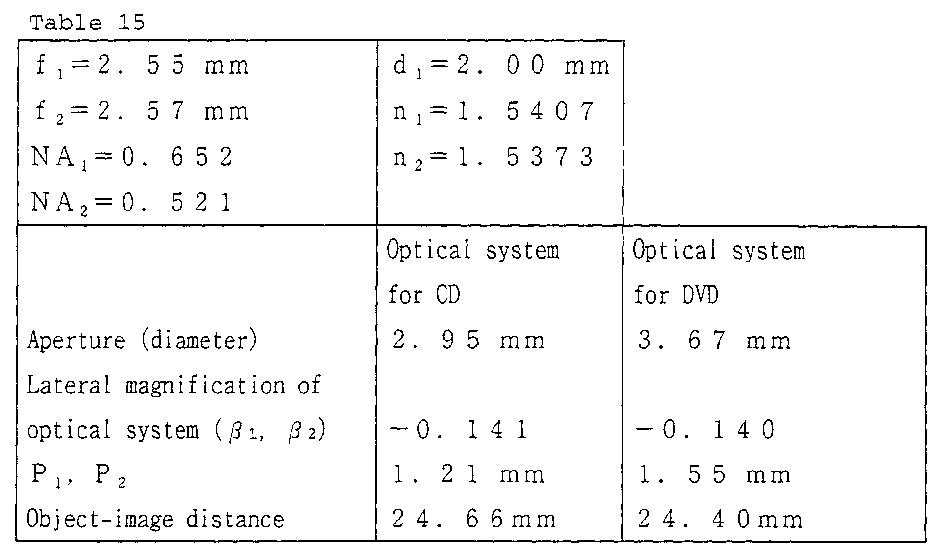
Table 15 shows basic specifications of the objective lens.
Specifications such as wavelength which are not described
in Table 15 are the same as those of Example 4.
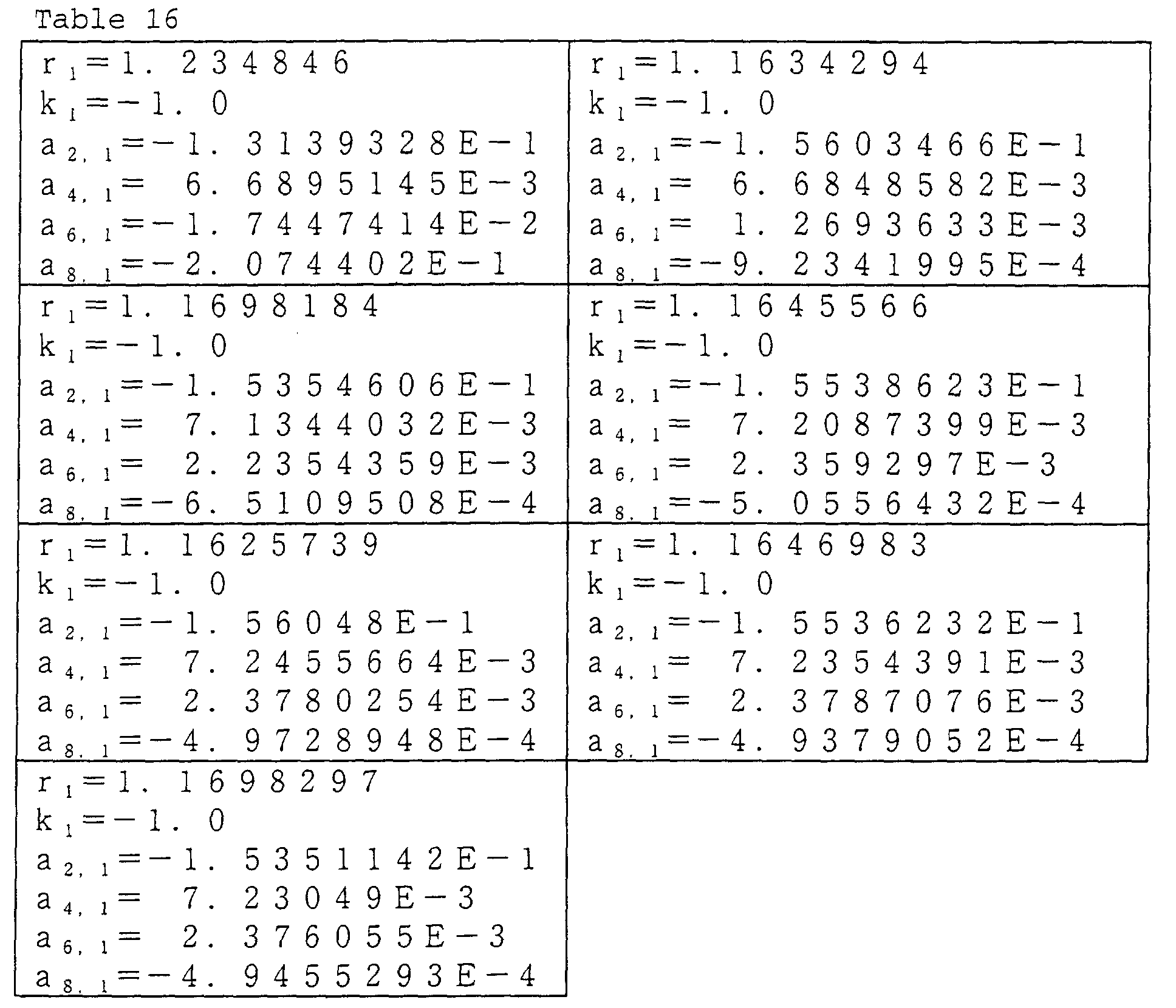
Table 16 shows coefficients of each aspheric surface
in the surface at a light source side of the objective
lens. The arrangement of Table 16 is the same as that of
Table 10.
Table 17 shows coefficients of each aspheric surface
in the surface at an optical disks of the objective lens.
The arrangement of Table 17 is the same as that of Table
11.
| r2=-3.318011 | r2=-3.3430456 |
| k2=-10 | k2=-10 |
| a2,2=6.9401748E-3 | a2,2=7.0902766E-3 |
| a4,2=1.8184351E-2 | a4,2=1.9972318E-2 |
| a6,2=-8.0507917E-2 | a6,2=-1.1906001E-2 |
| a8,2=-2.869907E-1 | a8,2=-1.999556E-2 |
| r2=-3.3502186 | r2=-3.352159 |
| k2=-10 | k2=-10 |
| a2,2=7.135788E-3 | a2,2=7.1767339E-3 |
| a4,2=2.0668896E-2 | a4,2=2.0824246E-2 |
| a6,2=-7.671281E-3 | a6,2=-6.7437767E-3 |
| a8,2=-3.0715885E-3 | a8,2=7.695503E-4 |
| r2=-3.3482377 | r2=-3.3523753 |
| k2=-10 | k2=-10 |
| a2,2=7.152478E-3 | a2,2=7.1766873E-3 |
| a4,2=2.0850797E-2 | a4,2=2.0831735E-2 |
| a6,2=-6.8047193E-3 | a6,2=-6.7902997E-3 |
| a8,2=6.6269524E-4 | a8,2=6.6924933E-4 |
Each head in the surface 3 at a light source of the
objective lens was the same (Table 12) as that of the
objective lens of Example 6. Each head in the surface at
a side of the disks of the objective lens 3 was also the
same (Table 13) as that of the objective lens of Example
6. The outer diameter of each aspheric surface of the
objective lens 3 was the same (Table 14) as that of the
objective lens of Example 6.
FIG. 21 shows the off-axial wavefront aberration
characteristics of the optical system for CD. FIG. 22
shows the off-axial wavefront aberration characteristics
of the optical system for DVD. An objective lens of
Example 7 was prepared by injection-molding a plastic
material and optical device as shown in FIG. 5 was
fabricated. When recording or reading was conducted to
CD and DVD with this optical device, accurate recording
or reading could be performed for both.
The objective lens of the present invention is
provided with the first phase shifter in a surface of the
lens, which has function to produce a phase difference
with respect to light having the first wavelength and the
second phase shifter in the other surface of the lens,
which has function to produce a phase difference with
respect to light having the second wavelength.
Accordingly, when recording or reading is conducted to
the first optical disk and the second optical disk, both
the on-axial aberration and the off-axial aberration can
be corrected well.
Accordingly, the objective lens of the present
invention provides excellent on-axial aberration and off-axial
aberration even when an inclination of the light
source or the objective lens from the optical axis or a
shift of axis of it is caused with the lapse of time.
Further, in the objective lens, it is easy to increase
precision, and a possibility that the optical performance
decreases with the lapse of time is little.
The entire disclosure of Japanese Patent Application
No. 2000-099580 filed on March 31, 2000 including
specification, claims, drawings and summary are
incorporated herein by reference in its entirety.