BACKGROUND OF THE INVENTION
The present invention relates generally to a method of
recording much information in a magnetic recording medium in
single operation, and more particularly to a method of
transferring recording information to a large-capacity, high-recording
density magnetic recording medium.
The quantity of information used with personal
computers, etc. are now dramatically increased because of
wide use of digital images, etc. With an increasing amount
of information, there are now demanded mass-storage magnetic
recording media that cost less and have ever-shorter write
and read time.
High-density recording media such as hard disks and a
high-density floppy disk type of magnetic recording media
have an information recording area provided with tracks
narrower than those used with ordinary floppy disks. To
precisely scan narrow track widths with a magnetic head
thereby recording and reading signals with high S/N ratios,
precise scanning must be effected using tracking servo
technology.
For this reason, mass-storage magnetic recording media
such as hard disks and removal types of magnetic recording
media represented by ZIP (Iomega Co., Ltd.) are currently
subjected to the so-called preformatting wherein tracking
servo signals, address information signals, read clock
signals, etc. are preformatted in one track at a certain
interval.
The magnetic head reads these preformatted signals to
make correction for its own position, so that it can run over
the tracks.
To fabricate a current preformat, a disk is recorded one
by one and track by track, using a dedicated servo recorder.
The servo recorder is expensive and long is needed for
preformatting, resulting in an increased production time.
This has some influences on production costs.
For this reason, a magnetic transfer system has been
proposed instead of the track-by-track preformatting system.
For instance, some transfer techniques are introduced in JP-A's
63-183623, 10-40544 and 10-269566. However, these
publications say nothing about practical conditions for
magnetic fields applied for magnetic transfer and practical
means for generating such magnetic fields.
To provide a solution to such prior art problems, for
instance, JP-A's 63-183623 and 10-40544 disclose a recording
method. According to this method, a substrate is provided on
its surface with a pit-and-projection configuration
corresponding to information signals. Then, a ferromagnetic
thin film is formed on the surface of at least the projection
portion of the pit-and-projection configuration to form a
magnetic transfer master carrier. While the surface of the
master carrier is brought in contact with the surface of a
sheet or disk form of magnetic recording medium having a
ferromagnetic thin film or ferromagnetic powder coating
layer, the ferromagnetic material forming the surface of the
projection portion is energized by the application of an a.c.
bias magnetic field or d.c. magnetic field, thereby recording
a magnetization pattern corresponding to the pit-and-projection
form on the magnetic recording medium.
In the aforesaid method, the surface of the projection
portion of the master carrier is brought in close contact
with the magnetic recording medium to be preformatted, i.e.,
a slave medium. At the same time, the ferromagnetic material
forming the projection portion is energized by transfer to
form a given format on the slave medium. Thus, this method
is characterized in that static recording is feasible without
any relative displacement of the slave medium with respect to
the magnetic transfer master carrier and so precise preformat
recording is feasible. In addition, this method is
characterized in that the time needed for recording is very
short. Here it is noted that the problems with the aforesaid
recording method using a magnetic head are that the recording
time of a few minutes to a few tens of minutes is usually
needed and the time needed for recording increases further
proportional to recording capacity. With the magnetic
transfer method, however, it is possible to finish transfer
within 1 second irrespective of recording capacity and
recording density.
Preformatting pattern transfer from the magnetic
transfer master carrier is here explained with reference to
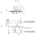
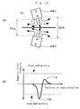
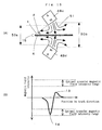
Figs. 1(A) and 1(B). Fig. 1(A) is a plane view in schematic
form illustrating a magnetic layer surface of the magnetic
transfer master carrier, and Fig. 1(B) is a sectional view
illustrative of one transfer process.
A magnetic transfer master carrier 1 is provided at a
given track area with a preformat area 2 having a pattern
comprising the tracking serve signals and address signals to
be transferred, and a data area 3. While the magnetic
transfer master carrier 1 is brought in close contact with a
slave medium 4, a transfer external magnetic field 6 is
applied in a track direction 5, thereby transfer preformat
information on the slave medium side in the form of recording
information 7. Thus, the slave medium can be fabricated with
high efficiency.
When transfer is carried out by such a method, however,
it is found that the quality of some information signals
often becomes worse with inaccurate servo operation.
An object of the present invention is therefore to
provide a stable transfer method and system which can prevent
inaccurate servo operation of a slave medium fabricated by a
preformat pattern transfer process where while a magnetic
transfer master carrier and a slave medium are brought in
close contact with each other, an external magnetic field is
applied to the salve medium.
BRIEF DESCRIPTION OF THE DRAWINGS
Figs. 1(A) and 1(B) are illustrative of pattern transfer
by a magnetic transfer master carrier.
Figs. 2(A), 2(B) and 2(C) are illustrative of a transfer
method and system using a single permanent magnet having a
magnetic field for a slave medium surface, which is
symmetrical with respect to the center axis of a magnetic
pole.
Figs. 3(A) and 4(B) are illustrative of another magnetic
field application method.
Figs. 4(A) and 4(B) are illustrative of yet another
magnetic application method.
Figs. 5(A), 5(B) and 5(C) are illustrative of how
magnetic fields produced by two juxtaposed permanent magnets
are applied to one surface of the slave medium.
Figs. 6(A) and 6(B) are illustrative of pattern transfer
from the master carrier to the slave medium.
Figs. 7(A), 7(B) and 7(C) are illustrative of how
magnetic fields produced by two juxtaposed permanent magnets
are applied to one surface of the slave medium.
Figs. 8(A), 8(B) and 8(C) are illustrative of one
embodiment of a permanent magnet wherein the end faces of
both magnetic poles thereof are directed to a slave medium
surface so that a magnetic field is applied by both magnetic
poles to a slave medium.
Figs. 9(A) and 9(B) are illustrative of pattern transfer
from a master carrier to a slave medium.
Figs. 10(A), 10(B) and 10(C) are illustrative of how to
apply a magnetic field produced by an electromagnet to one
surface of a slave medium.
Figs. 11(A) and 11(B) are illustrative of another
magnetic field application method.
Figs. 12(A) and 12(B) are illustrative of pattern
transfer from a master carrier to a slave medium.
Figs. 13(A), 13(B) and 13(C) are illustrative of how two
opposite electromagnets are used for the application of a
magnetic field.
Figs. 14(A) and 14(B) are illustrative of another
magnetic field application method.
Figs. 15(A) and 15(B) are illustrative of yet another
magnetic field application method.
Figs. 16(A), 16(B) and 16(C) are illustrative of how two
pairs of juxtaposed electromagnets are positioned with a
slave medium sandwiched therebetween, so that magnetic fields
are applied vertically to the surfaces of a slave medium.
Figs. 17(A) and 17(B) are illustrative of pattern
transfer from a master carrier to a slave medium.
Figs. 18(A) through 18(E) are illustrative of how to
apply a magnetic field using an electromagnet with the axis
of a magnetic pole parallel with a slave medium surface.
Figs. 19(A) and 19(B) are illustrative of pattern
transfer from a master carrier to a slave medium.
Figs. 20(A), 20(B) and 20(C) are illustrative of how two
juxtaposed electromagnets are used to apply a magnetic field
to one surface of a slave medium.
Figs. 21(A) and 21(B) are illustrative of pattern
transfer from a master carrier to a slave medium.
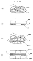
Figs. 22(A) through 22(D) are illustrative of a magnetic
field application method using an annular electromagnet.
Fig. 23 is illustrative of another annular
electromagnet.
Figs. 24(A) and 24(B) are illustrative of pattern
transfer from a master carrier to a slave medium.
SUMMARY OF THE INVENTION
The aforesaid objects are achievable by any one of the
following inventions (1) to (22).
a magnetic field is previously applied to said slave
medium in a track direction to initially d.c. magnetize said
slave medium in said track direction, and said magnetic
transfer master carrier is brought in close contact with said
initially d.c. magnetized slave medium to apply said transfer
magnetic field to said slave medium in said track direction
for magnetic transfer. (2) The magnetic transfer method according to (1)
above, wherein said magnetic layer of said magnetic transfer
master carrier has a coercive force Hcm of 600 Oe (48 kA/m) or
lower. (3) The magnetic transfer method according to (1)
above, wherein said associated slave medium has a coercive
force Hcs of 1,800 Oe (143 kA/m) or more. (4) The magnetic transfer method according to (1)
above, wherein the direction of said initial d.c.
magnetization of said slave medium by application of said
magnetic field in said track direction is opposite on a slave
medium surface to that of said transfer magnetic field
applied for magnetic transfer. (5) The magnetic transfer method according to (1)
above, wherein a magnetic field having a magnetic field
intensity profile having a magnetic field intensity portion
exceeding said coercive force Hcs of said slave medium at at
least one position in said track direction is generated at a
part of said track direction to rotate said slave medium or
said magnetic field in said track direction, so that said
magnetic field for said initial d.c. magnetization of said
slave medium in said track direction is applied to said slave
medium. (6) The magnetic transfer method according to (1)
above, wherein a magnetic field having a magnetic field
intensity profile, which has a magnetic field intensity
portion exceeding said coercive force Hcs of said slave medium
in one direction alone at a track direction position and in
which a magnetic strength in an opposite direction is less
than said coercive force Hcs of said slave medium at any track
direction position, is generated at a part of said track
direction to rotate said slave medium or said magnetic field
in said track direction, so that said magnetic field for said
initial d.c. magnetization of said slave medium in said track
direction is applied to said slave medium. (7) The magnetic transfer method according to (1)
above, wherein a magnetic field having a magnetic field
intensity profile, in which a magnetic strength exceeding a
maximum value of an optimum transfer magnetic field intensity
range is absent in any track direction, at least one portion
having a magnetic field intensity within said optimum
transfer magnetic strength field range is present in one
track direction and a magnetic field intensity in an opposite
direction thereto is less than a minimum value of said
optimum transfer magnetic field intensity range at any track
direction position, is generated at a part of said track
direction to rotate said slave medium in said track direction
while said initially d.c. magnetized slave medium is brought
in close contact with said or rotate said magnetic field in
said track direction, so that said transfer magnetic field is
applied to a slave medium surface in said track direction. (8) The magnetic transfer method according to (5)
above, wherein a magnetic pole axis of a permanent magnet is
located vertically on one of upper and lower surface sides of
said slave medium to apply to said slave medium a magnetic
field symmetrical with respect to said magnetic pole axis to
rotate said slave medium or said permanent magnet in said
track direction, so that said slave medium is initially d.c.
magnetized in said track direction. (9) The magnetic transfer method according to (6)
above, wherein a magnetic pole axis of a permanent magnet is
located obliquely with respect to a slave medium surface to
make an asymmetrical magnetic field intensity profile in said
track direction and rotate said slave medium or said
permanent magnet in said track direction, so that said slave
medium is initially d.c. magnetized in said track direction. (10) The magnetic transfer method according to (7)
above, wherein an axis of a magnetic pole of a permanent
magnet is located obliquely with respect to a slave medium
surface to make an asymmetrical magnetic field intensity
profile in said track direction and said initially d.c.
magnetized slave medium is rotated in said track direction
while said slave medium is brought in close contact with said
magnetic transfer master carrier or said magnetic field is
rotated in said track direction, so that said transfer
magnetic field is applied to said slave medium in said track
direction. (11) The magnetic transfer method according to (7) or
(10), wherein an optimum transfer magnetic field intensity is
given by 0.6 x Hcs to 1.3 x Hcs where Hcs is the coercive
force of said slave medium. (12) A magnetic transfer system in which a magnetic
transfer master carrier having a magnetic layer at a surface
portion of a substrate having an information signal is
brought in close contact with an associated slave medium and
a transfer magnetic field is applied to the slave medium,
which comprises:
initial d.c. magnetization means for previously applying
a magnetic field to said slave medium in a track direction to
initially d.c. magnetize said slave medium in said track
direction, and transfer magnetic field application means for applying a
transfer magnetic field to said initially d.c. magnetized
slave medium in said track direction while said magnetic
transfer master carrier is brought in close contact with said
initially d.c. magnetized slave medium. (13) The magnetic transfer system according to (12)
above, wherein said magnetic layer of said magnetic transfer
master carrier has a coercive force Hcm of 600 Oe (48 kA/m) or
more. (14) The magnetic transfer system according to (12)
above, wherein said associated slave medium has a coercive
force Hcs of 1,800 Oe (143 kA/m) or lower. (15) The magnetic transfer system according to (12)
above, wherein the direction of said initial d.c.
magnetization of said slave medium by application of said
magnetic field in said track direction is opposite on a slave
medium surface to said transfer magnetic field applied for
magnetic transfer. (16) The magnetic transfer system according to (12)
above, wherein said initial d.c. magnetization means
comprises means for generating a magnetic field having a
magnetic field intensity profile, which has a magnetic field
intensity portion exceeding said coercive force Hcs of said
slave medium at at least one position in said track
direction, at a part of said track direction and rotating
said slave medium or said magnetic field in said track
direction. (17) The magnetic transfer system according to (12)
above, wherein said initial d.c. magnetization means
comprises means for generating a magnetic field having a
magnetic field intensity profile, which has a magnetic field
intensity portion exceeding said coercive force Hcs of said
slave medium in one direction alone at a track direction
position and in which a magnetic strength in an opposite
direction is less than said coercive force Hcs of said slave
medium at any track direction position, at a part of said
track direction to rotate said slave medium or said magnetic
field in said track direction, so that said magnetic field
for said initial d.c. magnetization of said slave medium in
said track direction is applied to said slave medium. (18) The magnetic transfer system according to (12)
above, wherein said transfer magnetic field application means
comprises means for generating a magnetic field having a
magnetic field intensity profile, in which a magnetic
strength exceeding a maximum value of an optimum transfer
magnetic field intensity range is absent in any track
direction, at least one portion having a magnetic field
intensity within said optimum transfer magnetic strength
field range is present in one track direction and a magnetic
field intensity in an opposite direction thereto is less than
a minimum value of said optimum transfer magnetic field
intensity range at any track direction position, at a part of
said track direction, and means for rotating said slave
medium in said track direction while said initially d.c.
magnetized slave medium is brought in close contact with said
or rotating said magnetic field in said track direction, so
that said transfer magnetic field is applied to a slave
medium surface in said track direction. (19) The magnetic transfer system according to (16)
above, which comprises initial d.c. magnetization means
including a single permanent magnet for locating a magnetic
pole axis of said permanent magnet vertically on one of upper
and lower surface sides of said slave medium to apply to said
slave medium a magnetic field symmetrical with respect to
said magnetic pole axis, and means for rotating said slave
medium or said permanent magnet in said track direction, so
that said slave medium is initially d.c. magnetized in said
track direction. (20) The magnetic transfer system according to (17)
above, which comprises initial d.c. magnetization means
including a single permanent magnet for locating a magnetic
pole axis of said permanent magnet obliquely with respect to
a slave medium surface to make an asymmetrical magnetic field
intensity profile in said track direction and means for
rotating said slave medium or said permanent magnet in said
track direction, so that said slave medium is initially d.c.
magnetized in said track direction. (21) The magnetic transfer system according to (18)
above, wherein said transfer magnetic field application means
comprises a single permanent magnet magnetized in a vertical
direction with respect to a slave medium surface and located
obliquely with respect to said slave medium surface and on
one of upper and lower surface sides of said slave medium to
make an asymmetrical magnetic field intensity profile in said
track direction and means for rotating said initially d.c.
magnetized slave medium in said track direction while said
slave medium is brought in close contact with said magnetic
transfer master carrier or rotating said magnetic field in
said track direction, so that said transfer magnetic field is
applied to said slave medium in said track direction for
magnetic transfer. (22) The magnetic transfer system according to (18) or
(21) above, wherein an optimum transfer magnetic field
intensity is given by 0.6 x Hcs to 1.3 x Hcs where Hcs is the
coercive force of said slave medium.
DESCRIPTION OF THE PREFERRED EMBODIMENT
The present invention has been accomplished through the
inventors' findings that unstable transfer and low signal
quality upon the application of an external transfer magnetic
field to a slave medium in close contact with a magnetic
transfer master carrier are caused due to the fact that the
applied magnetic field is improper.
When an external magnetic field higher than the coercive
force Hcs of the slave medium is applied to the slave medium
for magnetic transfer from a magnetic transfer master carrier
thereto, there is a general perception that the whole slave
medium is magnetized in the direction of the applied magnetic
field, and so the pattern to be essentially transferred
cannot be recorded. For instance, JP-A 10-40544 teaches at
the paragraph [0064] that the applied magnetic field should
preferably be equal to or less than the coercive force of a
magnetic recording medium.
According to the inventors' studies concerning the
principle of magnetic transfer, it has now been found that an
external transfer magnetic field 6 is absorbed in a convex
form of magnetic layer of a magnetic transfer master carrier
1 which is in substantial contact with a slave medium 4, as
shown in Fig. 1(B). Consequently, the magnetic layer of the
slave medium 4 in contact with the magnetic transfer master
carrier 1 cannot have a magnetic field intensity at which
recording is feasible, but the magnetic layer of the slave
medium 4 corresponding to a concave portion of the magnetic
transfer master carrier 1 in no contact with the slave medium
4 can have a magnetic field intensity at which recording is
feasible. This in turn allows the magnetic layer of the
slave medium 4 to be magnetized in the direction of the
external transfer magnetic field 6, as shown by 7 in Fig.
1(B), so that the preformatting pattern on the magnetic
transfer master carrier 1 can be transferred to the slave
medium 4 in the form of recording information 7.
It is thus believed that in transfer from the magnetic
transfer master carrier to the slave medium, the portion of
the master carrier in contact with the slave medium is not
inverted even when a transfer magnetic field higher than the
coercive force Hcs is applied to the slave medium. This is
because a large part of the magnetic field strikes on the
pattern portion on the magnetic transfer master carrier. In
other words, it is possible to obtain a slave medium of high
signal quality by the application of a transfer magnetic
field having a specific strength as compared with the
coercive force Hcs of the slave medium.
To achieve clear transfer irrespective of any pattern,
it is preferable that the slave medium is initially d.c.
magnetized in one direction using a sufficiently large
magnetic field greater than the coercive force Hcs, preferably
a magnetic field at least 1.2 times as high as the coercive
force Hcs, followed by application of a transfer magnetic
field having a specific strength, i.e., a magnetic field
within the optimum transfer magnetic strength range. The
preferable transfer magnetic field is represented by
0.6 x Hcs ≤ Transfer Magnetic Field ≤ 1.3 x Hcs
This transfer magnetic field is applied in the opposite
direction to the direction of the initial d.c. magnetization.
The transfer magnetic field is more preferably between
0.8 Hcs and 1.2 Hcs, and even more preferably between 1 Hcs
and to 1.1 Hcs.
The magnetic recording medium to be servo preformatted
is generally a disk form of recording medium in which
information is recorded along tracks drawn concentrically
from the center of rotation. When a magnetic field is
applied to such a disk form of magnetic recording medium for
radial pattern transfer, the magnetic field is previously
applied to a slave medium surface in its track direction,
i.e., at an arbitrary track direction position and in a
tangential direction of a circular arc to initially d.c.
magnetize the slave medium in the track direction.
Then, the magnetic transfer master carrier is brought in
close contact with the initially d.c. magnetized slave medium
to apply the transfer magnetic field to a slave medium
surface in its track direction for magnetic transfer. In
this case, it is required that the direction of initial d.c.
magnetization of the slave medium by the previous application
of the magnetic field in the track direction be opposite on
the slave medium surface to that of the transfer magnetic
field applied for magnetic transfer.
To apply the magnetic field satisfying the above applied
magnetic field requirement all over the surface of the disk
form of recording medium, it is preferable to initially d.c.
magnetize the slave medium by generating a magnetic field
having a magnetic field intensity profile, which has a
magnetic field intensity portion exceeding the coercive force
Hcs of the slave medium at at least one position in the track
direction, at a part of said track direction and allowing the
slave medium or the magnetic field to make one rotation in
the track direction.
It is also preferable to initially d.c. magnetize the
slave medium in the track direction by producing a magnetic
field having a magnetic field intensity profile, which has a
magnetic field intensity portion exceeding the coercive force
Hcs of the slave medium in one direction alone at a track
direction position and in which a magnetic strength in an
opposite direction thereto is less than the coercive force Hcs
of the slave medium at any track direction position, at a
part of the track direction and allowing the slave medium or
the magnetic field to make one rotation in the track
direction.
According to the present invention, it is preferable to
generate a magnetic field having a magnetic field intensity
profile, in which a magnetic strength exceeding a maximum
value of an optimum transfer magnetic field intensity range
is absent in any track direction, at least one portion having
a magnetic field intensity within said optimum transfer
magnetic strength field range is present in one track
direction and a magnetic field intensity in an opposite
direction thereto is less than a minimum value of said
optimum transfer magnetic field intensity range at any track
direction position, at a part of said track direction and
rotating the initially d.c. magnetized slave medium in the
track direction while the initially d.c. magnetized slave
medium is brought in close contact with the magnetic transfer
master carrier or rotating the magnetic field in the track
direction, so that the transfer magnetic field is applied to
the slave medium surface in the track direction.
According to the method of the present invention, it is
also preferable to locate the axis of the magnetic pole of
the permanent magnet obliquely with respect to the slave
medium surface to provide an inclined transfer magnetic
field. Preferably in this case, the optimum value of
inclination of the axis of the magnetic pole should be such
that the angle between the surface vertical to the axis of
the magnetic pole and the slave medium surface is between 5°
and 70°, and especially between 20° and 55° for a cuboidal
permanent magnet, although varying depending on the
configuration of the magnet.
The permanent magnet used for the initial d.c.
magnetization and magnet transfer according to the present
invention should preferably have a size equal to or larger
than the distance between one end track and the other end
track end on the slave medium. When the slave medium is a
disk medium, the permanent magnet should preferably have a
size equal to or larger than the radial distance between the
outermost track and the innermost track. By use of the
permanent magnet having such a size, it is possible to apply
a uniform magnetic field to the slave medium surface. For
this, it is only required to allow any one of the slave
medium, an integral piece obtained by bringing the slave
medium in close contact with the magnetic transfer master
carrier and the permanent magnet to move in one direction
along the overall track length or make one rotation.
The magnetic field intensity applied using the permanent
magnet is required to be uniform throughout all track
positions, i.e., have a strength variation of within
preferably ±5%, and more preferably ±2.5% at all track
positions.
While the present invention has been explained with
reference to the embodiments wherein the permanent magnet is
used to apply a magnetic field to the slave medium and
magnetic transfer master carrier, it is understood that an
electromagnet may be used to apply a magnetic field thereto.
The electromagnet, too, may be located such that its
magnetic pole axis is inclined with respect to the slave
medium surface. Preferably in this case, the optimum value
of inclination of the magnetic pole axis should be such that
the angle between the surface vertical to the axis of the
magnetic pole and the slave medium surface is between 5° and
70°, and especially between 20° and 55° for a cuboidal
electromagnet, although varying depending on the
configuration of the magnet.
The electromagnet used for the initial d.c.
magnetization and magnet transfer according to the present
invention should preferably have a size equal to or larger
than the distance between one end track and the other end
track end on the slave medium. When the slave medium is a
disk medium, the permanent magnet should preferably have a
size equal to or larger than the radial distance between the
outermost track and the innermost track. By use of the
permanent magnet having such a size, it is possible to apply
a uniform magnetic field to the slave medium surface. For
this, it is only required to allow any one of the slave
medium, an integral piece obtained by bring the slave medium
in close contact with the magnetic transfer master carrier
and the permanent magnet to move in one direction along the
overall track length or make one rotation.
The magnetic field intensity applied using the
electromagnet is required to be uniform throughout all track
positions, i.e., have a strength variation of within
preferably ±5%, and more preferably ±2.5% at all track
positions.
When the electromagnet is used as the magnet in the
transfer method and system of the present invention, it is
possible to control the strength of the magnetic field acting
on the slave medium by controlling the distance between the
electromagnet and the slave medium, the inclination of the
electromagnet with respect to the slave medium surface and
the value of an exciting current fed to the electromagnet
and, hence, effect magnetic transfer for various slave media
and magnetic transfer master carriers having varying coercive
forces.
A number of embodiments of the transfer method and
system of the present invention are now explained with
reference to the accompanying drawings.
In the embodiment of the transfer method and system of
the present invention shown in Figs. 2(A) through 2(C), a
single permanent magnet having a symmetrical magnetic field
for a slave medium surface, which is symmetrical with respect
to the center axis of the magnetic pole.
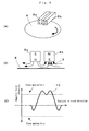
Fig. 2(A) is illustrative of how the slave medium is
rotated while a magnetic field is applied by a permanent
magnet 8 to the upper surface of a slave medium 4.
While a parallel magnetic field 9 in the track direction
is applied from the single permanent magnet 8 provided over
the upper surface of the slave medium 4 to the surface of the
slave medium as shown in Fig. 2(B), the slave medium or the
permanent magnet is rotated in the track direction with
respect to the center axis of the slave medium. A magnetic
field having a peak 10 exceeding the coercive force Hcs of the
slave medium, as shown in Fig. 2(C), is applied to the
surface of the slave medium for the initial d.c.
magnetization thereof. Although the permanent magnet is
provided over the upper surface side of the slave medium as
shown in Fig. 2(A), it is understood the permanent magnet may
be provided on the lower surface side of the slave medium.
Then, the slave medium is brought in close contact with
the magnetic transfer master carrier. Subsequently, a
magnetic field in the opposite direction to the initial d.c.
magnetization direction is applied to the slave medium, so
that the pattern on the magnetic transfer master carrier can
be transferred to the slave medium.
Alternatively, a single permanent magnet magnetized
vertically with respect to the slave medium surface may be
positioned obliquely with respect to either one of the upper
and lower surface sides of the slave medium to create an
asymmetrical magnetic field intensity profile in the track
direction. In this setting, the slave medium or the
permanent magnet is rotated, thereby initially d.c.
magnetizing the slave medium or transferring the pattern on
the magnetic transfer master carrier to the slave medium.
Another magnetic field application method is shown in
Figs. 3(A) and 3(B).
The application of an inclined magnetic field is
illustrated in Fig. 3(A) and the magnetic field intensity
obtained by the application of the magnetic field illustrated
in Fig. 3(A) is illustrated in Fig. 3(B).
Figs. 3(A) and 3(B) are illustrative of how an initial
d.c. magnetic field is applied to the surface of a slave
medium 4 using a gradient permanent magnet 11. An inclined
magnetic field 9 is applied to the slave medium 4 to rotate
the slave medium 4 or the gradient permanent magnet 11 in the
track direction with respect to the center axis of the slave
medium and thereby apply an asymmetrical magnetic field to
the slave medium, so that the slave medium can be initially
d.c. magnetized.
One peak 13 of reduced strength has no influence on the
initial d.c. magnetization of the slave medium at all; only
another peak 14 of increased strength takes part in the
initial d.c. magnetization.
Yet another magnetic field application method is shown
in Figs. 4(A) and 4(B).
The application of an inclined magnetic field is
illustrated in Fig. 4(A) and the magnetic field intensity
obtained by the application of the magnetic field illustrated
in Fig. 4(A) is illustrated in Fig. 4(B).
Fig. 4(A) is illustrative of how to apply a transfer
magnetic field to the surface of an integral piece 15
comprising a slave medium 4 and a magentic transfer master
carrier 1 close contact therewith, using an inclined
permanent magnet 11. An inclined transfer magnetic field 12
is applied to the integral piece 15 to rotate the inclined
permanent magnet 11 or the integral piece 15 in the track
direction with respect to the center axis of the integral
piece 15, whereby a magnetic field in the opposite direction
to that of the initial d.c. magnetization is applied thereto.
A reduced-strength peak 16 of the asymmetrical magnetic
field shows no influence at all on transfer of pattern
transfer from the magnetic transfer master carrier to the
slave medium; only a peak 17 of increased strength
contributes to magnetic transfer.
The peak 17 of increased strength allows the optimum
range of transfer magnetic field to be applied from the
magnetic transfer master carrier to the slave medium, thereby
making it possible to form a satisfactory pattern
irrespective of the configuration of the pattern.
By allowing the strengths of the initial d.c. magnetic
field and transfer magnetic field to have a proper magnitude,
it is thus possible to form a preferable transfer pattern.
The systems used for the magnetic transfer methods shown
in Figs. 2 through 4 are each provided with a mechanism
capable of arbitrarily controlling the distance between the
slave medium and the permanent magnet. By controlling the
distance between the slave medium and the permanent magnet,
the desired magnetic field intensity can be obtained on the
surface of the slave medium.
In addition to the distance control mechanism, each of
the systems shown in Figs. 3 and 4 is provided with a
mechanism capable of arbitrarily controlling the angle of
inclination of the permanent magnet, so that the strength of
the magnetic field in the opposite direction to that of
initial d.c. magnetization or the magnetic transfer magnetic
filed can be controlled as desired.
Each of the methods of Figs. 3 and 4 is nothing but one
example of making an asymmetrical magnetic field profile at
the track direction position using a substantially single
permanent magnet. For instance, the asymmetrical magnetic
field profile may be obtained by changing the configuration
of the surface of the permanent magnet opposite to the slave
medium or providing one block of combined permanent magnets
or making inhomogeneous the magnetic material used for the
permanent magnet. In this case, too, a magnetic pattern
having such an asymmetrical strength profile as shown in
Figs. 3 and 4 may be obtained.
Further embodiments of the transfer methods and systems
according to the present invention are now explained with
reference to the drawings.
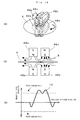
Figs. 5(A) through 5(C) are illustrative of how two
permanent magnets are juxtaposed over one surface of a slave
medium to apply a magnetic field to the slave medium.
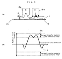
As shown in Fig. 5(A), two permanent magnets 8a and 8b
are juxtaposed over at least one surface of a slave medium 4
in such a way that the magnetic pole directions of both
magnets are opposite to each other, i.e., the polarities of
the adjacent magnetic poles are opposite to each other, with
the respective magnetic pole axes located vertically with
respect to the slave medium. In such a setting, the slave
medium 4 is rotated.
As explained above, the two permanent magnets 8a and 8b
are juxtaposed over at least one surface of the slave medium
4 in such a way that the magnetic pole directions of both
magnets are opposite to each other, i.e., the polarities of
the adjacent magnetic poles are opposite to each other, with
the respective magnetic pole axes located vertically with
respect to the slave medium. As shown in Fig. 5(B), one
permanent magnet 8a produces a magnetic field toward another
permanent magnet 8b, and so provides a magnetic field 9 to be
applied to the surface of the slave medium 4.
Fig. 5(C) is a diagram illustrative of the strength of
the magnetic field applied to the slave medium. In the
magnetic field applied to the slave medium, a peak 10
exceeding the coercive force Hcs of the slave medium is found,
so that the slave medium can be initially d.c. magnetized by
rotating the slave medium or the two permanent magnets.
If the slave medium is brought in close contact with a
magnetic transfer master carrier and a magnetic field is
applied in the opposite direction to the initial d.c.
magnetization direction according to such a similar method as
mentioned above, it is then possible to achieve pattern
transfer from the magnetic transfer master carrier to the
slave medium.
The distance between the juxtaposed magnets may be such
that the magnetic field having a strength exceeding the
coercive force of the slave medium can be applied to the
slave medium.
Figs. 6(A) and 6(B) are illustrative of how the pattern
on the magnetic transfer master carrier is transferred to the
slave medium.
Fig. 6(A) is illustrative of how a magnetic field is
applied to an integral piece obtained by bringing the slave
medium in close contact with the magnetic transfer master
carrier, and Fig. 6(B) is a diagram illustrative of the
strength of the magnetic field applied as shown in Fig. 6(A).
Permanent magnets 8a and 8b, each having a symmetrical
magnetic field with respect to its magnetic pole axis, are
juxtaposed over the upper surface of an integral piece 15
comprising a slave medium 4 and a magnetic transfer master
carrier 1 in close contact therewith in such a way that the
polarities of the adjacent magnetic poles are opposite to
each other, with the respective magnetic pole axes located
vertically with respect to the integral piece. In this
setting, the integral piece 15 is rotated.
As explained above, the permanent magnets 8a and 8b are
juxtaposed over the upper surface of the integral piece 15 in
such a way that the polarities of the adjacent magnetic poles
are opposite to each other. As shown, one permanent magnet
8a produces a magnetic field toward another permanent magnet
8b, and so applies a transfer magnetic field 12 to the
integral piece 15.
Fig. 6(B) is a diagram illustrative of the strength of
the magnetic field applied to the slave medium in close
contact with the magnetic transfer mater carrier.
A reduced-strength peak 13 of the strength profile of
the magnetic field applied to the slave medium is so much
smaller than the optimum transfer magnetic field intensity
range that it has no influence at all on pattern transfer
from the master carrier to the slave medium. Only a peak 14
of increased strength contributes to magnetic transfer. The
peak 14 of increased strength also makes it possible to apply
to the slave medium a magnetic field included in the optimum
transfer magnetic field intensity range for pattern transfer
from the magnetic transfer master carrier to the slave
medium, thereby forming a satisfactory pattern irrespective
of the configuration of the pattern.
The system used for each of the magnetic transfer
methods shown in Figs. 5 and 6 is provided with a mechanism
capable of arbitrarily controlling the distance between the
slave medium and the permanent magnets and the distance
between the juxtaposed permanent magnets. By controlling the
distance between the slave medium and the permanent magnets
and the distance between the juxtaposed permanent magnets, it
is thus possible to obtain the desired magnetic field
intensity on the slave medium surface.
Figs. 7(A) through 7(C) are illustrative of the transfer
method and system of the present invention wherein a single
permanent magnet is located over a slave medium surface with
the end faces of both its magnetic poles opposing to the
slave medium surface.
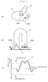
As shown in Fig. 7(A), a permanent magnet 8 is located
over the upper surface of a slave medium 4 with the end faces
39a and 39b of both its magnetic poles opposing to the slave
medium 4, thereby applying a magnetic field to the slave
medium 4. In this setting, the slave medium is rotated.
While parallel magnetic fields 9 in a track direction
are applied from the end faces 39a and 39b of both magnetic
poles of the single permanent magnet 8 located over the upper
surface of the slave medium 4 to the slave medium surface, as
shown in Fig. 7(B), the slave medium or the permanent magnet
is rotated in the track direction with respect to the center
axis of the slave medium. A magnetic field having a peak 10
exceeding the coercive force Hcs of the slave medium such as
one shown in Fig. 7(C) is applied to the slave medium surface
so that it is initially d.c. magnetized. In the embodiment
of Fig. 7(A), one permanent magnet is located over the upper
surface of the slave medium. However, it is understood that
one permanent magnet may be located on the lower surface side
of the slave medium or two permanent magnets may be located
over both surfaces of the slave medium.
Then, the slave medium is brought in close contact with
the magnetic transfer master carrier, whereupon a magnetic
field is applied to the slave medium in a direction opposite
to that of the initial d.c. magnetization, so that a pattern
on the magnetic transfer master carrier can be transferred to
the slave medium.
The magnet used herein to apply the magnetic field to
the slave medium or the integral piece comprising the slave
medium and the magnetic transfer master carrier in close
contact therewith may be any one of U-shaped magnets,
horseshoe-shaped magnets, circular magnets, oval magnets and
so on. The end faces of the magnet poles of the magnet used
herein may be parallel with the slave medium surface as well
as inclined with respect to the slave medium surface.
Figs. 8(A) through 8(D) are illustrative of one
embodiment of the permanent magnet that can be located over a
slave medium surface with the end faces of both its magnetic
poles opposing to the slave medium surface, so that both the
magnetic poles can apply a magnetic field to the slave
medium.
A permanent magnet 8 shown in Fig. 8(A) has the end
faces 39a and 39b of both its magnetic poles inclined
outwardly with respect to a slave medium surface at an angle
of outward inclination 1, whereas the permanent magnet of
Fig. 7(A) has both its end faces parallel with the slave
medium.
The angle of outward inclination 1 should be preferably
30° or smaller, and more preferably 10° or smaller.
A permanent magnet 8 shown in Fig. 8(B) has the center
axes of both its magnetic poles crossing over themselves
rather than parallel with each other, whereas the permanent
magnet of Fig. 7(A) is a U-shaped permanent magnet having the
end faces 39a and 39b of both its magnetic poles parallel
with the slave medium 4.
The end faces of both magnetic poles act as shown in
Fig. 7(A) with the exception of their configurations, and so
apply a magnetic field to the slave medium 4.
A permanent magnet 8 shown in Fig. 8(C) is the same as
that of Fig. 8(B) with the exception that the end faces 39a
and 39b of both its magnetic poles are inclined inwardly with
respect to the surface of a slave medium 4 at an angle of
inward inclination 2. The angle of inward inclination 2 of
the end faces with respect to the slave surface should be
preferably 90° or smaller, and more preferably 30° or
smaller.
In the permanent magnet shown in Fig. 8(C), the center
axes of both its magnetic poles cross over themselves.
Instead of this permanent magnet, it is acceptable to use a
U-shaped permanent magnet in which the center axes of both
its magnetic poles are parallel with each other and the end
faces of both its magnetic poles have an angle of inward
inclination.
A permanent magnet 8 shown in Fig. 8(D) has a generally
oval configuration, with the end faces 39a and 39b of both
its magnetic poles inclined inwardly with respect to the
surface of a slave medium 4 at an angle of inward inclination
3.
As shown in Fig. 8(C), the angle of inward inclination 3
of the end faces with respect to the slave surface should be
preferably 90° or smaller, and more preferably 30° or
smaller.
The permanent magnet used for the initial d.c.
magnetization and magnet transfer according to the present
invention should preferably have a size equal to or larger
than the distance between one end track and the other end
track end on the slave medium. When the slave medium is a
disk medium, the permanent magnet should preferably have a
size equal to or larger than the radial distance between the
outermost track and the innermost track. By use of the
permanent magnet having such a size, it is possible to apply
a uniform magnetic field to the slave medium surface. For
this, it is only required to allow any one of the slave
medium, an integral piece comprising the slave medium and the
magnetic transfer master carrier in close contact therewith
and the permanent magnet to move in one direction along the
overall track length or make one rotation.
The magnetic field intensity applied using the permanent
magnet is required to be uniform throughout all track
positions, i.e., have a strength variation of within
preferably ±5%, and more preferably ±2.5% at all track
positions.
Figs. 9(A) and 9(B) are illustrative of how to apply a
magnetic field to an integral piece comprising a slave medium
and a magnetic transfer master carrier in close contact
therewith.
Fig. 9(A) is illustrative of the application of the
magnetic filed, and Fig. 9(B) is a diagram illustrative of
the strength of the magnetic field obtained by the
application of the magnetic field as shown in Fig. 9(A).
A U-shaped permanent magnet 8 is located over the
surface of an integral piece 15 comprising a slave medium 4
and a magnetic transfer master carrier 1 in close contact
therewith while the end faces of its magnetic poles oppose to
the slave medium, thereby applying a magnetic field 12 to the
integral piece 15. In this state, the integral piece or the
permanent magnet is rotated in a track direction with respect
to the center axis of the integral piece, whereby a magnetic
field is applied to the integral piece in the opposite
direction to that of the initial d.c. magnetization.
A reduced-strength peak 13 of the magnetic field has no
influence at all on pattern transfer from the magnetic
transfer master carrier to the slave medium. Only a peak 14
of increased strength contributes to magnetic transfer.
The peak 14 of increased strength also makes it possible
to produce a magnetic field included in the optimum transfer
magnetic field intensity for pattern transfer from the
magnetic transfer master carrier to the slave medium, thereby
forming a satisfactory pattern irrespective of the
configuration of the pattern.
Even when the permanent magnet shown in Figs. 8(A)
through 8(D) is used instead of the permanent magnet of Figs.
9(A) and 9(B), a preferable transfer pattern can be formed by
allowing the strength of the transfer magnetic field to have
a proper magnitude.
In the above embodiment, the permanent magnet is located
on one surface side of the slave medium to apply a magnetic
field thereto. It is understood that two permanent magnets
may be located on both surface sides of the slave medium.
The system used to carry out the magnetic transfer
method shown in Figs. 9(A) and 9(B) is provided with a
mechanism capable of arbitrarily controlling the distance
between the slave medium surface and the permanent magnet.
By controlling the distance between the slave medium surface
and the permanent magnet, it is possible to obtain the
desired magnetic field intensity on the slave medium surface.
Figs. 10(A) through 10(B) are illustrative of the method
of locating an electromagnet over one surface of a slave
medium to apply a magnetic field thereto.
Fig. 10(A) is illustrative of how a slave medium is
rotated while the magnetic field is applied by the
electromagnet thereto, Fig. 10(B) is illustrative of the
magnetic field applied to the slave medium, and Fig. 10(C) is
a diagram illustrative of the strength of the magnetic field
applied to the slave medium.
As shown in Fig. 10(A), a single electromagnet 48
located over the upper surface of a slave medium 4 is d.c.
energized upon receipt of a direct current from a d.c. power
source 49, and the axis of the magnetic pole formed by the
electromagnet 48 is positioned vertically with respect to the
slave medium surface.
As shown in Fig. 10(B), a magnetic field 9 is applied in
parallel with the surface of the slave medium 4, whereby, as
shown in Fig. 10(C), a magnetic field having a peak 10
exceeding the coercive force Hcs of the slave medium is
applied to the slave medium for the initial d.c.
magnetization thereof. In the embodiment of Fig. 10(A), the
electromagnet is provided over the upper surface of the slave
medium. However, it is understood that the electromagnet may
be provided on the lower surface side of the slave medium.
Figs. 11(A) and 11(B) are illustrative of another
magnetic field application method.
Fig. 11(A) is illustrative of the application of an
inclined magnetic field, and Fig. 11(B) is a diagram
illustrative of the strength of the magnetic field applied as
shown in Fig. 11(A).
According to this embodiment, a d.c. energized inclined
electromagnet 31 is used to apply an initial d.c. magnetic
field to the surface of a slave medium 4. An inclined
magnetic field 32 is applied to the slave medium 4 to rotate
the slave medium 4 or the inclined electromagnet 31 in a
track direction with respect to the center axis of the slave
medium, so that the slave medium can be initially d.c.
magnetized by the application of an asymmetrical magnetic
field thereto.
Of peaks applied to the slave medium, one peak 13 of
reduced strength has no influence at all on the initial d.c.
magnetization of the slave medium. Only a peak 14 of
increased strength has an action on the initial d.c.
magnetization of the slave medium.
The strength of the magnetic field applied to the slave
medium may be controlled by changing the energizing current
for the electromagnet, the distance between the electromagnet
and the slave medium, the angle of inclination of the
inclined electromagnet, etc.
Figs. 12(A) and 12(B) are illustrative of the pattern
transfer method from a magnetic transfer master carrier to a
slave medium.
Fig. 12(A) is illustrative of how a magnetic field is
applied to an integral piece comprising a slave medium and a
magnetic transfer master carrier in close contact therewith,
and Fig. 12(B) is a diagram illustrative of the strength of
the magnetic field applied as shown in Fig. 12(A).
A d.c. energized inclined electromagnet 31 is located
over the upper surface of an integral piece 15 comprising a
slave medium 4 and a magnetic transfer master carrier 1 in
close contact therewith to rotate the integral piece 15 or
the inclined electromagnet 31 in a track direction with
respect to the center axis of the integral piece 15, whereby
an asymmetrical magnetic field is applied to the integral
piece for magnetic transfer.
A reduced-strength peak 13 of the strength profile of
the magnetic field applied to the slave medium is so much
smaller than the optimum transfer magnetic field intensity
range that it has no influence at all on pattern transfer
from the master carrier to the slave medium. Only a peak 14
of increased strength contributes to magnetic transfer. The
peak 14 of increased strength also makes it possible to apply
to the slave medium a magnetic field included in the optimum
transfer magnetic field intensity range for pattern transfer
from the magnetic transfer master carrier to the slave
medium, thereby forming a satisfactory pattern irrespective
of the configuration of the pattern.
The system used to carry out the magnetic transfer
method shown in Figs. 12(A) is provided with a mechanism
capable of controlling the distance between the slave medium
surface and the electromagnet, the inclination of the
electromagnet, the energizing current, etc. By controlling
the distance between the slave medium and the electromagnet,
it is possible to obtain the desired magnetic field intensity
on the slave medium surface. The electromagnet used herein
may be any one of air-core solenoid coils and coils having an
iron or other core at their centers.
Figs. 13(A) through 13(C) are illustrative of the method
of applying a magnetic field using two electromagnets.
As shown in Fig. 13(A), electromagnets 48a and 48b
magnetized symmetrically with respect to their magnetic pole
axes are located over the upper and lower surfaces of a slave
medium 4 while the same magnetic poles are opposite to each
other. In this setting, the slave medium is then rotated.
Energizing currents are applied from d.c. power sources 49a
and 49b to the electromagnets 48a and 48b, respectively.
Magnetic fields 9 are applied to the surfaces of the slave
medium 4 from the electromagnets 48a and 48b provided on the
upper and lower surface sides of the slave medium 4.
Fig. 13(C) is a diagram illustrative of the magnetic
field intensity applied to the slave medium. In the magnetic
field applied to the slave medium, a peak 10 exceeding the
coercive force Hcs of the slave medium is so found that the
slave medium can be initially d.c. magnetized by rotating the
slave medium or rotating the electromagnets.
Figs. 14(A) and 14(B) are illustrative of another
magnetic field application method.
Fig. 14(A) is illustrative of how an asymmetrical
magnetic field is applied, and Fig. 14(B) is a diagram
illustrative of the strength of the magnetic field applied as
shown in Fig. 14(A).
Electromagnets 48c and 48d, which are magnetized
symmetrically with respect to their magnetic pole axes using
a d.c. energizing current, are located with a slave medium 4
positioned between the opposing same magnetic poles thereof.
The electromagnets are then obliquely arranged in such a way
that the distance 50a between the electromagnets at one end
in a track direction differs from the distance 50b between
the electromagnets at the other end, thereby generating an
asymmetrical magnetic field intensity profile in the track
direction. Asymmetrical magnetic fields 51 are applied to
the surfaces of the slave medium 4 to rotate the slave medium
4 or the inclined electromagnets 48c and 48d in the track
direction with respect to the center axis of the slave medium
4, so that all the surfaces of the slave medium are initially
dc. magnetized by the application of the asymmetrical
magnetic fields thereto.
One reduced-strength peak 13 of the asymmetrical
magnetic field has no influence at all on the initial d.c.
magnetization of the slave medium, and only a peak 14 of
increased strength has an action on the initial d.c.
magnetization of the slave medium.
Figs. 15(A) and 15(B) are illustrative of yet another
magnetic field application method.
Fig. 15(A) is illustrative of how an asymmetrical
magnetic field is applied to an integral piece comprising a
slave medium and a master carrier in close contact therewith,
and Fig. 15(B) is a diagram illustrative of the strength of a
magnetic field applied as in Fig. 15(A).
Electromagnets 48c and 48d, which are magnetized
symmetrically with respect to their magnetic pole axes using
a d.c. energizing current, are located with an integral piece
15 positioned between the opposing same magnetic poles
thereof, said integral piece 15 comprising an initially d.c.
magnetized slave medium 4 and a master carrier 1 in close
contact therewith. The electromagnets are then obliquely
arranged in such a way that the distance 50a between the
electromagnets at one end in a track direction differs from
the distance 50b between the electromagnets at the other end,
thereby generating an asymmetrical magnetic field intensity
profile in the track direction. Thus, an asymmetrical
magnetic field 51 is applied to the surface of the slave
medium 4, thereby rotating at least one of the integral piece
15 and the inclined electromagnets 48c and 48d, so that
magnetic fields can be applied to all the surfaces of the
integral piece 15 in the opposite direction to that of the
initial d.c. magnetization.
One reduced-strength peak 13 of the asymmetrical
magnetic field has no influence at all on pattern transfer
from the magnetic transfer master carrier to the slave
medium, and only a peak 14 of increased strength contributes
to magnetic transfer.
The peak 14 of increased strength ensures a magnetic
field included within the maximum transfer magnetic field
intensity range for pattern transfer from the magnetic
transfer master carrier to the slave medium, and so a
satisfactory pattern can be formed irrespective of the
configuration of the pattern to be transferred.
The system used to carry out each of the magnetic
transfer methods of Figs. 13 to 15 is provided with a
mechanism capable of arbitrarily controlling the distance of
the slave medium surface and the electromagnets and the
energizing current supplied to the electromagnets. By
controlling at least one of the distance of the slave medium
surface and the electromagnets and the energizing current, it
is thus possible to obtain the desired magnetic field
intensity on the slave medium surface.
In addition to the distance control mechanism, each of
the systems shown in Figs. 14 and 15 is provided with a
mechanism capable of arbitrarily controlling the angle of
inclination of the electromagnets, so that the strength of
the magnetic field in the opposite direction to that of
initial d.c. magnetization or the magnetic transfer magnetic
filed can be controlled as desired. The electromagnets used
herein may be any one of air-core solenoid coils or coils
having iron or other cores at their centers.
Each of the methods of Figs. 14 and 15 is nothing but
one example of making an asymmetrical magnetic field profile
at the track direction position using substantially two
electromagnets. For instance, the asymmetrical magnetic
field profile may be obtained by changing the configuration
of the surface of the electromagnets opposite to the slave
medium or providing one block of combined small
electromagnets or making inhomogeneous the magnetic material
used for the electromagnets. In this case, too, a magnetic
pattern having such an asymmetrical strength profile as shown
in Figs. 14 and 15 may be obtained.
Figs. 16(A) through 16(C) are illustrative of how to
apply a magnetic field to a slave medium surface from two
pairs of electromagnets positioned vertically to the slave
medium surface while the slave medium is sandwiched between
them.
As shown in Fig. 16(A), one pair of electromagnets 48a
and 48b having a magnetic field symmetrical with respect to
their magnetic pole axes are positioned on the upper and
lower surface sides of a slave medium 4 with the same
magnetic magnetic poles opposing to each other. Another pair
of electromagnets 48c and 48d are juxtaposed to the one pair
of electromagnets 48a and 48b in such a way that the
polarities of the former are opposite to those of the latter.
In such settings, the slave medium 4 is rotated. From
associated d.c. power sources 49a, 49b, 49c and 49d, d.c.
energizing currents are supplied to the electromagnets 48a,
48b, 48c and 48d.
As explained above, the electromagnets 48a and 48b are
independently positioned on the upper and lower surface sides
of the slave medium 4 with the same poles opposing to each
other. As shown in Fig. 16(B), the magnetic fields of 48a
and 48b repel each other and the magnetic field of 48a
directs toward the adjacent electromagnet 48c while the
magnetic field of 48b directs toward the adjacent magnets
48d. Thus, a magnetic field 9 is applied to the surface of
the slave medium 4.
Fig. 16(C) is a diagram illustrative of the strength of
the magnetic field applied to the slave medium. The magnetic
field applied to the slave medium has a peak 11 exceeding the
coercive force Hcs of the slave medium, and so the slave
medium can be initially d.c. magnetized by rotating the slave
medium or the rotating the electromagnets.
The distance between the juxtaposed electromagnets
should preferably be such that they can apply to the slave
medium a magnetic filed having a strength of greater than the
coercive force of the slave medium.
Figs. 17(A) and 17(B) are illustrative of the transfer
method from a magnetic transfer master carrier to a slave
medium.
Fig. 17(A) is illustrative of the application of a
magnetic field to an integral piece comprising a slave medium
and a master carrier in close contact therewith, and Fig.
7(B) is a diagram illustrative of the strength of the
magnetic field applied as shown in Fig. 7(A).
As shown in Fig. 17(A), one pair of electromagnets 48a
and 48b having a magnetic field symmetrical with respect to
their magnetic pole axes are positioned on the upper and
lower surface sides of an integral piece 15 with the same
magnetic poles opposing to each other, said integral piece 15
comprising a slave medium 4 and a master carrier 1 in close
contact therewith. Another pair of electromagnets 48c and
48d are juxtaposed to the one pair of electromagnets 48a and
48b in such a way that the polarities of the former are
opposite to those of the latter. In such settings, the
integral piece 15 is rotated.
As explained above, the electromagnets 48a and 48b are
independently positioned on the upper and lower surface sides
of the integral piece 15 with the same poles opposing to each
other. The magnetic fields of 48a and 48b repel each other
and the magnetic field of 48a directs toward the adjacent
electromagnet 48c while the magnetic field of 48b directs
toward the adjacent magnets 48d. Thus, a transfer magnetic
field 12 is applied to the surface of the integral piece 15.
Fig. 17(B) is a diagram illustrative of the magnetic
field intensity applied to the slave medium in close contact
with the magnetic transfer master carrier.
A reduced-strength peak 13 of the strength profile of
the magnetic field applied to the slave medium is so much
smaller than the optimum transfer magnetic field intensity
range that it has no influence at all on pattern transfer
from the master carrier to the slave medium. Only a peak 14
of increased strength contributes to magnetic transfer. The
peak 14 of increased strength also makes it possible to apply
to the slave medium a magnetic field included in the optimum
transfer magnetic field intensity range for pattern transfer
from the magnetic transfer master carrier to the slave
medium, thereby forming a satisfactory pattern irrespective
of the configuration of the pattern.
The system used for each of the magnetic transfer
methods shown in Figs. 16 and 17 is provided with a mechanism
capable of arbitrarily controlling the distance between the
slave medium and the electromagnets and the distance between
the juxtaposed one pair of electromagnets. By controlling
the distance between the slave medium and the electromagnets
and the distance between one pair of electromagnets, it is
thus possible to obtain the desired magnetic field intensity
on the slave medium surface. The electromagnets used herein
may be any one of air-core solenoid coils or coils having
iron or other cores at the centers.
Figs. 18(A) through 18(E) are illustrative of how a
magnetic field is applied using a single transverse
electromagnet. Fig. 18(A) is illustrative of how an
electromagnet 48 having a magnetic field symmetrical with
respect to its magnetic pole axis is rotated over the upper
surface of a slave medium 4 while the magnetic pole axes is
positioned parallel with the surface of the slave medium 4.
From the single electromagnet 48 positioned over the
upper surface of the slave medium 4 a magnetic field 9 is
applied to the surface of the slave medium 4, as shown in
Fig. 18(B).
Fig. 18(C) is a diagram illustrative of the strength of
the magnetic field applied to the slave medium. The magnetic
field applied to the slave medium has a peak 10 exceeding the
coercive force Hcs of the slave medium, and so the slave
medium can be initially d.c. magnetized by the rotation of
the slave medium or the electromagnet.
In the embodiment shown in Fig. 18(D), electromagnets
48a and 48b, each having a magnetic field symmetrical with
respect to its magnetic pole axis, are rotated on both
surface sides of a slave medium 4 while the magnetic pole
axes are located parallel with the surface of the slave
medium 4 in the same direction. From the electromagnets 48a
and 48b positioned on both surface sides of the slave medium
4, one for each side, magnetic fields 9 are applied to the
surfaces of the slave medium 4, as shown in Fig. 18(E).
Figs. 19(A) through 19(C) are illustrative of the
transfer method from a magnetic transfer master carrier to a
slave medium.
Fig. 19(A) is illustrative of the application of a
magnetic field to an integral piece comprising a slave medium
and a master carrier in close contact therewith. Fig. 19(B)
is a diagram illustrative of the strength of the magnetic
field applied as shown in Fig. 19(A).
A single electromagnet 48, which has a magnetic field
symmetrical with respect to its magnetic pole axis and
produces a magnetic field exceeding the coercive force Hcs of
the slave medium in a track direction, is positioned over the
surface of an integral piece 15 comprising a slave medium 4
and a master carrier 1 in close contact therewith to apply a
magnetic field 9 to the integral piece 15, thereby rotating
at least one of the integral piece 15 and the electromagnet
48 in the track direction with respect to the center axis of
the integral piece 15, so that a magnetic field can be
applied all over the surface of the integral piece 15 in the
opposite direction to that of the initial d.c. magnetization.
A reduced-strength peak 13 of the applied magnetic field
has no influence on pattern transfer from the magnetic
transfer master carrier to the slave medium; that is, only a
peak 14 of increased strength contributes to magnetic
transfer.
The peak 14 of increased strength also makes it to apply
to the integral piece a magnetic field included within the
optimum transfer magnetic field intensity range for pattern
transfer from the magnetic transfer master carrier to the
slave medium, so that a satisfactory pattern can be formed
irrespective of the configuration of the pattern to be
transferred.
In the embodiment shown in Fig. 19(C), electromagnets
48a and 48b, each having a magnetic field symmetrical with
respect to its magnetic pole axis and capable of producing a
magnetic field of greater than the coercive force Hcs of the
slave medium, are positioned on both surface sides of the
integral piece 15 to apply a transfer magnetic field 12
thereto. In this setting, at least one of the integral piece
and the electromagnets is rotated in the track direction with
respect to the center axis of the integral piece, thereby
applying to the whole surface of the integral piece a
magnetic field in the opposite direction to that of the
initial d.c. magnetization. In this case, the increased-strength
peak of the magnetic field has a magnetic transfer
action.
The system used to carry out each of the magnetic
transfer methods shown in Figs. 18 and 19 is provided with a
mechanism capable of arbitrarily controlling the distance
between the slave medium surface and the electromagnet(s) and
a mechanism for controlling the energizing current for the
electromagnet(s). By controlling the distance between the
slave medium and the electromagnet(s) and the energizing
current, it is thus possible to obtain the desired magnetic
field intensity on the slave medium surface.
The electromagnet(s) used herein may be air-core
solenoid coils or coils having iron or other cores at their
centers.
Figs. 20(A), 20(B) and 20(C) are illustrative of how two
electromagnets 48a and 48b are juxtaposed over one surface of
a slave medium to apply a magnetic field thereto.
As shown in Fig. 20(A), two electromagnets 48a and 48b
are juxtaposed over one surface of a slave medium 4 with
their magnet pole axes located vertically to the slave medium
in such a way that their magnetic pole directions are
opposite to each other, i.e., the polarities of adjacent
magnetic poles are opposite to each other. In this setting,
the slave medium 4 is rotated.
As explained above, the two electromagnets 48a and 48b
are juxtaposed over at least one surface of the slave medium
4 with their magnet pole axes located vertically to the slave
medium in such a way that their magnetic pole directions are
opposite to each other, i.e., the polarities of adjacent
magnetic poles are opposite to each other. As shown in Fig.
20(B), one electromagnet 48a generates a magnetic field
directing toward another electromagnet 48b juxtaposed
thereto, so that a magnetic field 9 can be applied to the
surface of the slave medium 4.
Fig. 20(C) is a diagram illustrative of the strength of
the magnetic field applied to the slave medium. The magnetic
field applied to the slave medium has a peak 10 exceeding the
coercive force Hcs of the slave medium, so that the slave
medium can be initially d.c. magnetized by the rotation of
slave medium or the two electromagnets.
By use of a similar method, a magnetic field in the
opposite direction to that of the initial d.c. magnetization
can be applied to a slave medium in close contact with a
master carrier to transfer a pattern on the master carrier to
the slave medium.
The distance between the juxtaposed electromagnets
should preferably be such that they can apply to the slave
medium a magnetic field having a strength of greater than the
coercive force of the slave medium.
Figs. 21(A) and 21(B) are illustrative of the transfer
method from a magnetic transfer master carrier to a slave
medium.
Fig. 21(A) is illustrative of the application of a
magnetic field to an integral piece comprising a slave medium
and a master carrier in close contact therewith, and Fig.
21(B) is a diagram illustrative of the strength of the
magnetic field applied as shown in Fig. 21(A).
Electromagnets 48a and 48b, each having a magnetic field
symmetrical with respect to its magnetic pole axis, are
juxtaposed over the upper surface of an integral piece 15
comprising a slave medium 4 and a master carrier 1 in close
contact therewith in such a way that the polarities of the
adjacent magnetic poles are opposite to each other. In this
setting, the integral piece 15 is rotated while the magnetic
pole axes of the electromagnets are located vertically to the
integral piece.
As explained above, the independent electromagnets 48a
and 48b are juxtaposed over the upper surface of the integral
piece 15 with the polarities of the adjacent magnetic poles
opposite to each other. One electromagnet 48a produces a
magnetic field directing toward another electromagnet 48b, so
that a transfer magnetic field 12 can be applied to the
integral piece 15.
Fig. 21(B) is a diagram illustrative of the strength of
the magnetic field applied to the slave medium in close
contact with the magnetic transfer master carrier.
A reduced-strength peak 13 of the strength profile of
the magnetic field applied to the slave medium is so much
smaller than the optimum transfer magnetic field intensity
range that it has no influence on pattern transfer from the
master carrier to the slave medium; that is, only a peak 14
of increased strength contributes to magnetic transfer. The
peak 14 of increased strength also makes it possible to apply
to the slave medium a magnetic field included in the optimum
transfer magnetic field intensity range for pattern transfer
from the magnetic transfer master carrier to the slave
medium, thereby forming a satisfactory pattern irrespective
of the configuration of the pattern.
The system used for each of the magnetic transfer
methods shown in Figs. 20 and 21 is provided with a mechanism
capable of arbitrarily controlling the distance between the
slave medium and the electromagnets and the distance between
the juxtaposed electromagnets. By controlling the distance
between the slave medium and the electromagnets and the
distance between the juxtaposed electromagnets, it is thus
possible to obtain the desired magnetic field intensity on
the slave medium surface.
The electromagnets used herein may be any one of air-core
solenoid coils or coils having iron or other cores at
the centers.
Embodiments of the present invention wherein an annular
electromagnet is used as the electromagnet are now explained.
The magnetic recording medium to be servo preformatted
is generally a disk form of recording medium in which
information is recorded along tracks drawn concentrically
from the center of rotation. When a magnetic field is
applied to such a disk form of magnetic recording medium for
radial pattern transfer, the magnetic field is previously
applied to a slave medium surface in its track direction,
i.e., at an arbitrary track direction position and in a
tangential direction of a circular arc to initially d.c.
magnetize the slave medium in the track direction. In this
case, an annular electromagnet can be used to generate the
desired magnetic field.
Subsequently, the magnetic transfer master carrier is
brought in close contact with the initially d.c. magnetized
slave medium to apply the transfer magnetic field to a slave
medium surface in its track direction for magnetic transfer.
It is then required that the direction of initial d.c.
magnetization of the slave medium by the previous application
of the magnetic field in the track direction be opposite on
the slave medium surface to that of the transfer magnetic
field applied for magnetic transfer. In this case, the
annular electromagnet can be used to generate the desired
magnetic field.
In the present invention, the annular electromagnet used
for the initial d.c. magnetization and magnetic transfer
should preferably have an area that is approximately equal to
or larger than the track area. By use of an annular
electromagnet having such a size, it is possible to apply a
uniform magnetic field to the slave medium or an integral
piece comprising a slave medium and a master carrier in close
contact therewith.
It is noted that the annular electromagnet used herein
is an electromagnet produced by rotating a circle around a
center axis to form a torus or other annular member and
winding a coil having a size equivalent to the diameter of
the circle around the surface of the annular member, so that
a major magnetic line of force is formed within the annular
member. In the present invention, a magnetic line of force
formed on the outside of the annular member is used.
The coil wound around the surface of the annular member
may be not only circular but also oval in section. For
instance, the coil may have an oblate circular shape or a
rectangular shape optionally with circular arcs at both ends.
The annular electromagnet should preferably have a flat track
surface portion. The distance between the annular
electromagnet and the slave medium or the integral piece
should preferably be as short as possible or 0.5 mm to 20 mm.
The magnetic field to be applied by the annular
electromagnet should have a uniform strength at all track
positions or a strength variation of within ±5%, and
especially ±2.5% at all track positions.
Fig. 22(A) through 22(D) are illustrative of how a
magnetic field is applied using an annular electromagnet.
As shown in Fig. 22(A), an annular electromagnet 58 is
positioned over the upper surface of a slave medium 4 to
initially d.c. magnetize the slave medium 4.
From the annular electromagnet 58 positioned over the
upper surface of the slave medium 4, a magnetic field 59
leaking from the annular electromagnet is applied to the
surface of the slave medium 4, as shown in Fig. 22(B), so
that the slave medium can be initially d.c. magnetized.
In the embodiment shown in Fig. 22(C), annular
electromagnets 58a and 58b are positioned on the upper and
lower surface sides of a slave medium 4. From the annular
electromagnets 58a and 58b positioned on both surface sides
of the slave medium 4, one for each side, a magnetic filed 59
is applied to the surfaces of the slave medium 4, as shown in
Fig. 22(D).
The strength of the magnetic field applied from the
annular electromagnet to the slave medium surface may be
controlled by changing the strength of the current fed to the
annular electromagnet and the spacing between the annular
electromagnet and the slave medium surface.
Fig. 23 is illustrative of another embodiment of the
annular electromagnet.
The annular electromagnet shown in Fig. 23 is built up
of four distinct coils 21 through 24. By controlling the
current fed to each coil 21 to 24 and regulating the space 25
to 28 between adjacent coils, it is possible to control the
strength of the magnetic field applied to a slave medium
surface.
Figs. 24(A) and 24(B) are illustrative of the transfer
method from a magnetic transfer master carrier to a slave
medium as well as of the application of a magnetic field to
an integral piece comprising a slave medium and a master
carrier in close contact therewith.
As shown, an annular electromagnet 58 is positioned over
the surface of an integral piece 15 comprising a slave medium
4 and a master carrier 1 in close contact therewith to apply
a magnetic field 12 thereto, so that a magnetic field can be
applied to the whole surface of the integral piece 15 in the
opposite direction to that of initial d.c. magnetization.
The system used to carry out each of the magnetic
transfer methods shown in Figs. 22 to 24 is provided with a
mechanism capable of arbitrarily controlling the distance
between the slave medium surface and the annular
electromagnet and a mechanism for controlling the energizing
current for the electromagnet. By controlling the distance
between the slave medium and the annular electromagnet and
the energizing current, it is thus possible to obtain the
desired magnetic field intensity on the slave medium surface.
The annular electromagnet used herein may be an air-core
solenoid coil or a coil having an iron or other core at its
center.
How to fabricate the magnetic transfer master carrier
used in the present invention is now explained.
For the substrate for the magnetic transfer master
carrier, use may be made of a sheet substrate with a smooth
surface, which is formed of silicon, quartz, glass, non-magnetic
metals such as aluminum or their alloy, ceramics,
and synthetic resins. The substrate must be resistant to
treating temperature or other environments encountered at
etching and film-formation process steps.
A photoresist is coated on the substrate with a smooth
surface. Using a photomask corresponding to the desired
preformatting pattern, the photoresist is exposed to light
and developed to form a pattern corresponding to information
on the photoresist. Alternatively, the pattern may be drawn
directly on the photoresist.
Then, at the etching step the substrate is etched
corresponding to the pattern by means of any one of reactive
etching, physical etching using an argon plasma, and liquid
etching which may be selected depending on the substrate
used.
The depths of pits formed by etching should be
corresponding to the thickness of a magnetic layer formed as
a transfer information recording portion. However, it is
preferable that 20 nm ≤ pit depth ≤ 1,000 nm. Too large a
pit depth is not preferable because the magnetic field
breadth becomes large.
It is preferable to form pits of uniform depth so that
the bottom surfaces of the pits can be formed of planes
parallel with the surface of the substrate.
The pits should preferably have a rectangular shape in
the track direction section vertical to the plane.
Then, a film form of magnetic material is formed to the
surface of the substrate with a thickness corresponding to
the formed pits, using vacuum film deposition means such as
vacuum evaporation, sputtering and ion plating or plating
means. Referring here to the magnetic characteristics of the
transfer information recording portion, the coercivity (Hc) is
2,500 Oe or less and preferably 5 to 1,500 Oe, and the
saturated flux density (Bs) is 0.3 T (tesla) or more and
preferably 0.5 T or more.
Then, the photoresist is removed by a lift-off process,
and the substrate is polished on the surface for removal of
burrs, if any, followed by surface flattening.
The fabrication process wherein pits are first formed in
the substrate and a film form of magnetic material is then
formed in the pits has been explained. However, it is
acceptable to use a photo-fabrication process wherein a film
form of magnetic material is first formed at a given portion
on a substrate to form a projection portion as a transfer
information recording portion, and a non-magnetic material is
then formed or filled between projections to make the
transfer information recording portion flush with the non-magnetic
material portion.
For the magnetic layer, magnetic materials having high
magnetic flux densities such as cobalt, iron or their alloys
may be used. For instance, Co, CoPtCr, CoCr, CoPtCrTa,
CoPtCrNbTa, CoCrB, CoNi, Fe, FeCo and FePt may be used.
The magnetic layer should have a thickness of 20 to
1,000 nm, and preferably 30 to 500 nm. Too thick a magnetic
layer becomes poor in record resolving power.
In consideration of clear transfer, particular
preference is given to a magnetic material that has a high
magnetic flux density and is of magnetic anisotropy in the
same direction as the slave medium, for instance, in the
longitudinal direction in the case of longitudinal recording
and in the vertical direction in the case of vertical
recording. The magnetic material should also preferably a
fine magnetic particle or amorphous structure because sharp
edges can then be formed.
To impart magnetic anisotropy to the magnetic material,
it is preferable to provide a non-magnetic primer layer. In
this case, the non-magnetic primer layer is required to have
the same crystallographic structure and lattice constant as
those of the magnetic layer. Exemplary primer layers may be
formed by the sputtering of Cr, CrTi, CoCr, CrTa, CrMo, NiAl,
Ru, etc.
It is also preferable to provide a protective film such
as a diamond-like carbon film and a lubricating agent on the
magnetic layer. More preferably, a diamond-like carbon film
of 5 to 30 nm and a lubricating film are present in the form
of protective films, on which a lubricating agent should be
provided for the reason that in the absence of the
lubricating agent, durability becomes insufficient due to
friction caused by correction of a possible misalignment of
the slave medium with the master carrier.
The magnetic transfer master carrier according to the
present invention can be used not only for transfer of
magnetic recording information to a disk type of magnetic
recording media such as hard disks and removal type magnetic
recording media but also for transfer of magnetic recording
information to a card type of magnetic recording media and a
tape type of magnetic recording media.
EXAMPLE
The present invention is now explained with reference to
a number of examples.
Example 1-1 and Comparative Example 1-1
Preparation of Master Carrier
A vacuum film deposition system was evacuated at room
temperature to 10-7 Torr, and argon was then introduced in the
system until the condition of 3 x 10⁻³ Torr was obtained.
Under this condition, an FeCo film of 200 nm in thickness was
formed on a silicon substrate to prepare a magnetic transfer
master carrier.
The master carrier was found to have a coercive force Hc
of 100 Oe and a magnetic flux density Ms of 23,000 gausses.
The master carrier was then provided thereon with a
disk-like pattern comprising 10 µ wide radial lines at
regular intervals and a 20 mm to 40 mm position in the radial
direction from the center of the disk, with a line interval
of 10 µm at the innermost position spaced 20 mm away from the
center of the disk in the radial direction.
Preparation of Slave Medium
A vacuum film deposition system was evacuated at room
temperature to 10-7 Torr, and argon was then introduced in the
system until the condition of 3 x 10⁻³ Torr was obtained.
Under this condition, a glass plate was heated to 200°C to
prepare a disk form of magnetic recording medium of 3.5
inches in diameter, which was found to have a 25 nm thick
CoCrPt film with an Ms of 4,500 gausses and a coercive force
Hcs of 2,500 Oe.
Magnetic Transfer Testing
The initial d.c. magnetization of the slave medium was
carried out while a permanent magnet was located as shown in
Fig. 2, so that a peak magnetic strength of 5,000 Oe that was
twice that coercive force Hc of the slave medium was obtained
on the surface of the slave medium.
Then, the initially d.c. magnetized slave medium and the
magnetic transfer master carrier were brought into close
contact with each other. Using the system having an inclined
permanent magnet as shown in Fig. 4, a magnetic field was
applied in the opposite direction to the direction of
magnetization for magnetic transfer. The angle of
inclination of the permanent magnet with respect to the
slave medium was 35° in Fig. 4. To bring the slave medium
and the magnetic transfer master carrier in close contact
with each other, pressure was applied from above an aluminum
plate having a rubber plate provided on its lower side.
Estimation of Electromagnetic Performance
Signals transferred to the slave medium were estimated
using an electromagnetic performance measuring device (SS-60
made by Kyodo Denshi Co., Ltd.). For the head, use was made
of an MR head having a read head gap of 0.24 µm, a read track
width of 1.9 µ m, a write head gap of 0.4 µm and a write track
width of 2.4 µm.
Output signals were subjected to frequency analysis
using a spectro-analyzer to find a difference (C/N) between
the peak strength of the primary signal (C) and extrapolated
medium noise (N). Assuming that the maximum value of C/N at
each magnetic field intensity was 0 dB, estimation was made
in terms of relative values (ΔC/N). The results are shown in
Table 1-1. It is noted that the asterisk mark indicates a
C/N value of -20 dB or lower or that the quality of the
magnetically transferred signals is far from the practical
level.
| Hcs of Slave Medium: 2,500 Oe |
| Peak Strength Oe of Transfer Magnetic Field | Ratio to Hcs | ΔC/N (dB) |
| 750 | 0.3 | * |
| 1,250 | 0.5 | -16.3 |
| 1,500 | 0.6 | -3.2 |
| 2,000 | 0.8 | -0.6 |
| 2,250 | 0.9 | -0.3 |
| 2,500 | 1.0 | -0.1 |
| 2,750 | 1.1 | 0.0 |
| 3,000 | 1.2 | -3.5 |
| 3,250 | 1.3 | -3.8 |
| 3,500 | 1.4 | -10.2 |
| 3,750 | 1.5 | -16.9 |
| 4,000 | 1.6 | * |
| 5,000 | 2.0 | * |
The initial d.c. magnetization of a slave medium having
a coercive force Hcs of 2,500 Oe was carried out at a peak
magnetic field intensity of 3,000 Oe that was 1.2 times as
high as the coercive force Hcs of the slave medium. Then, the
initially d.c. magnetized slave medium and a magnetic
transfer master carrier were brought into close contact with
each other for magnetic transfer. Otherwise, the magnetic
transfer was carried out as in Example 1-1, and
electromagnetic performance was estimated as in Example 1-1.
The results are shown in Table 1-2.
| Hcs of Slave Medium: 2,500 Oe |
| Peak Strength Oe of Transfer Magnetic Field | Ratio to Hcs | ΔC/N (dB) |
| 750 | 0.3 | * |
| 1,250 | 0.5 | -13.6 |
| 1,500 | 0.6 | -2.9 |
| 2,000 | 0.8 | -2.1 |
| 2,250 | 0.9 | -0.8 |
| 2,500 | 1.0 | 0.0 |
| 2,750 | 1.1 | -0.3 |
| 3,000 | 1.2 | -1.4 |
| 3,250 | 1.3 | -2.4 |
| 3,500 | 1.4 | -10.2 |
| 3,750 | 1.5 | -19.6 |
| 4,000 | 1.6 | * |
| 5,000 | 2.0 | * |
The initial d.c. magnetization of a slave medium having
a coercive force Hcs of 2,500 Oe prepared as in Example 1-1
was carried out at a peak magnetic field intensity of 2,000
Oe that was four-fifths of the coercive force Hcs of the slave
medium. Then, the initially d.c. magnetized slave medium and
a magnetic transfer master carrier were brought into close
contact with each other for magnetic transfer. The magnetic
transfer was carried out as in Example 1-1 with the exception
that the system shown in Fig. 4 was used, and electromagnetic
performance was estimated as in Example 1-1. The results are
shown in Table 1-3.
| Hcs of Slave Medium: 2,500 Oe |
| Peak Strength Oe of Transfer Magnetic Field | Ratio to Hcs | ΔC/N (dB) |
| 750 | 0.3 | * |
| 1,250 | 0.5 | * |
| 1,500 | 0.6 | * |
| 2,000 | 0.8 | * |
| 2,250 | 0.9 | * |
| 2,500 | 1.0 | * |
| 2,750 | 1.1 | * |
| 3,000 | 1.2 | * |
| 3,250 | 1.3 | * |
| 3,500 | 1.4 | * |
| 3,750 | 1.5 | * |
| 4,000 | 1.6 | * |
| 5,000 | 2.0 | * |
The initial d.c. magnetization of a slave medium having
a coercive force Hcs of 2,500 Oe was carried out at peak
magnetic field intensitys of 5,000 Oe, 3,000 Oe and 2,000 Oe,
using the permanent magnet shown in Fig. 3. Then, the
initially d.c. magnetized slave medium and a magnetic
transfer master carrier were brought into close contact with
each other for magnetic transfer. Using the permanent magnet
shown in Fig. 4, a magnetic field was applied for magnetic
transfer.
The results were much the same as those obtained using
the system having the permanent magnet shown in Fig. 2.
Example 1-4 and Comparative Example 1-5
The initial d.c. magnetization of a slave medium having
a coercive force Hcs of 2,000 Oe prepared as in Example 1-1
was carried out at a peak magnetic field intensity of 4,000
Oe that was twice as high as the coercive force Hcs of the
slave medium. Then, the initially d.c. magnetized slave
medium and a magnetic transfer master carrier were brought
into close contact with each other for magnetic transfer
using the system shown in Fig. 4. Otherwise, the magnetic
transfer was carried out as in Example 1-1, and
electromagnetic performance was estimated as in Example 1-1.
The results are shown in Table 1-4.
| Hcs of Slave Medium: 2,000 Oe |
| Peak Strength Oe of Transfer Magnetic Field | Ratio to Hcs | ΔC/N (dB) |
| 600 | 0.3 | * |
| 1,000 | 0.5 | -18.2 |
| 1,200 | 0.6 | -4.8 |
| 1,600 | 0.8 | -3.2 |
| 1,800 | 0.9 | -0.1 |
| 2,000 | 1.0 | 0.0 |
| 2,200 | 1.1 | -0.2 |
| 2,400 | 1.2 | -0.8 |
| 2,600 | 1.3 | -2.3 |
| 2,800 | 1.4 | -9.6 |
| 3,000 | 1.5 | -16.3 |
| 3,200 | 1.6 | * |
| 4,000 | 2.0 | * |
The initial d.c. magnetization of a slave medium having
a coercive force Hcs of 2,000 Oe was carried out at a peak
magnetic field intensity of 2,400 Oe that was 1.2 times as
high as the coercive force Hcs of the slave medium. Then, the
initially d.c. magnetized slave medium and a magnetic
transfer master carrier were brought into close contact with
each other for magnetic transfer. Otherwise, the magnetic
transfer was carried out as in Example 1-1 to obtain a
magnetic transfer pattern, and electromagnetic performance
was estimated as in Example 1-1. The results are shown in
Table 1-5.
| Hcs of Slave Medium: 2,000 Oe |
| Peak Strength Oe of Transfer Magnetic Field | Ratio to Hcs | ΔC/N (dB) |
| 600 | 0.3 | * |
| 1,000 | 0.5 | -17.2 |
| 1,200 | 0.6 | -4.2 |
| 1,600 | 0.8 | -2.1 |
| 1,800 | 0.9 | -0.7 |
| 2,000 | 1.0 | 0.0 |
| 2,200 | 1.1 | 0.0 |
| 2,400 | 1.2 | -0.6 |
| 2,600 | 1.3 | -4.2 |
| 2,800 | 1.4 | -13.2 |
| 3,000 | 1.5 | -19.8 |
| 3,200 | 1.6 | * |
| 4,000 | 2.0 | * |
The initial d.c. magnetization of a slave medium having
a coercive force Hcs of 2,000 Oe was carried out at peak
magnetic field intensitys of 4,000 Oe, 2,400 Oe and 1,600 Oe,
using the permanent magnet shown in Fig. 3. Then, the
initially d.c. magnetized slave medium and a magnetic
transfer master carrier were brought into close contact with
each other for magnetic transfer. Using the permanent magnet
shown in Fig. 4, a magnetic field was applied for magnetic
transfer. The results were much the same as those obtained
using the system having the permanent magnet shown in Fig. 2.
Comparative Example 1-8
The initial d.c. magnetization of a slave medium having
a coercive force Hcs of 2,000 Oe prepared as in Example 1-1
was carried out at a peak magnetic field intensity of 1,600
Oe that was four-fifths of the coercive force Hcs of the slave
medium. Then, the initially d.c. magnetized slave medium and
a magnetic transfer master carrier were brought into close
contact with each other for magnetic transfer. The magnetic
transfer was carried out as in Example 1-1 with the exception
that the system shown in Fig. 4 was used, and electromagnetic
performance was estimated as in Example 1-1. The results are
shown in Table 1-6.
| Hcs of Slave Medium: 2,000 Oe |
| Peak Strength Oe of Transfer Magnetic Field | Ratio to Hcs | ΔC/N (dB) |
| 600 | 0.3 | * |
| 1,000 | 0.5 | * |
| 1,200 | 0.6 | * |
| 1,600 | 0.8 | * |
| 1,800 | 0.9 | * |
| 2,000 | 1.0 | * |
| 2,200 | 1.1 | * |
| 2,400 | 1.2 | * |
| 2,600 | 1.3 | * |
| 2,800 | 1.4 | * |
| 3,000 | 1.5 | * |
| 3,200 | 1.6 | * |
| 4,000 | 2.0 | * |
According to the above magnetic transfer from the
magnetic transfer master carrier to the slave medium, the
transfer magnetic field having a specific strength is applied
to the coercive force Hcs of the slave medium, thereby
imparting a high-quality transfer pattern to the slave medium
irrespective of the position and configuration of the
pattern.
Example 2-1 and Comparative Example 2-1
Preparation of Master Carrier
A vacuum film deposition system was evacuated at room
temperature to 10-7 Torr, and argon was then introduced in the
system until the condition of 3 x 10⁻³ Torr was obtained.
Under this condition, an FeCo film of 200 nm in thickness was
formed on a silicon substrate to prepare a disk-like master
carrier of 3.5 inches in diameter.
The master carrier was found to have a coercive force Hc
of 100 Oe and a magnetic flux density Ms of 23,000 gausses.
The master carrier was then provided thereon with a
disk-like pattern comprising 10 µ wide radial lines at
regular intervals and a 20 mm to 40 mm position in the radial
direction from the center of the disk, with a line interval
of 10 µm at the innermost position spaced 20 mm away from the
center of the disk in the radial direction.
Preparation of Slave Medium
A vacuum film deposition system was evacuated at room
temperature to 10-7 Torr, and argon was then introduced in the
system until the condition of 3 x 10⁻³ Torr was obtained.
Under this condition, a glass plate was heated to 200°C to
prepare a disk form of magnetic recording medium of 3.5
inches in diameter, which was found to have a 25 nm thick
CoCrPt film with an Ms of 4,500 gausses and a coercive force
Hcs of 2,500 Oe.
Initial DC Magnetization
The initial d.c. magnetization of the slave medium was
carried out by locating such a permanent magnet as shown in
Fig. 5 such that a peak magnetic field intensity of 5,000 Oe
that was twice as high as the coercive force Hcs of the slave
medium was obtained on the surface of the slave medium.
Magnetic Transfer Testing
The initially d.c. magnetized slave medium and the
magnetic transfer master carrier were brought into close
contact with each other. Using the system having an inclined
permanent magnet as shown in Fig. 6, a magnetic field was
applied in the opposite direction to the direction of
magnetization for magnetic transfer. To bring the slave
medium and the magnetic transfer master carrier in close
contact with each other, pressure was applied from above an
aluminum plate having a rubber plate provided on its lower
side.
Estimation of Electromagnetic Performance
Signals transferred to the slave medium were estimated
using an electromagnetic performance measuring device (SS-60
made by Kyodo Denshi Co., Ltd.). For the head, use was made
of an MR head having a read head gap of 0.27 µm, a read track
width of 2.4 µm, a write head gap of 0.4 µm and a write track
width of 3.1 µ m.
Output signals were subjected to frequency analysis
using a spectro-analyzer to find a difference (C/N) between
the peak strength of the primary signal (C) and extrapolated
medium noise (N). Assuming that the maximum value of C/N at
each magnetic field intensity was 0 dB, estimation was made
in terms of relative values (ΔC/N). The results are shown in
Table 2-1. It is noted that the asterisk mark indicates a
C/N value of -20 dB or lower or that the quality of the
magnetically transferred signals is far from the practical
level.
| Hcs of Slave Medium: 2,500 Oe |
| Peak Strength Oe of Transfer Magnetic Field | Ratio to Hcs | ΔC/N (dB) |
| 750 | 0.3 | * |
| 1,250 | 0.5 | -10.3 |
| 1,500 | 0.6 | -4.8 |
| 2,000 | 0.8 | -1.2 |
| 2,250 | 0.9 | -0.4 |
| 2,500 | 1.0 | 0.0 |
| 2,750 | 1.1 | -0.2 |
| 3,000 | 1.2 | -1.2 |
| 3,250 | 1.3 | -3.5 |
| 3,500 | 1.4 | -6.3 |
| 3,750 | 1.5 | -11.0 |
| 4,000 | 1.6 | * |
| 5,000 | 2.0 | * |
The initial d.c. magnetization of a slave medium having
a coercive force Hcs of 2,500 Oe was carried out at a peak
magnetic field intensity of 3,000 Oe that was 1.2 times as
high as the coercive force Hcs of the slave medium. Then, the
initially d.c. magnetized slave medium and a magnetic
transfer master carrier were brought into close contact with
each other for magnetic transfer. Otherwise, the magnetic
transfer was carried out as in Example 2-1, and
electromagnetic performance was estimated as in Example 2-1.
The results are shown in Table 2-2. The peak strength of the
transfer magnetic field shows a peak of the magnetic field
profile shown in Fig. 6(C).
| Hcs of Slave Medium: 2,500 Oe |
| Peak Strength Oe of Transfer Magnetic Field | Ratio to Hcs | ΔC/N (dB) |
| 750 | 0.3 | * |
| 1,250 | 0.5 | -9.2 |
| 1,500 | 0.6 | -2.6 |
| 2,000 | 0.8 | -2.5 |
| 2,250 | 0.9 | -0.5 |
| 2,500 | 1.0 | 0.0 |
| 2,750 | 1.1 | -0.2 |
| 3,000 | 1.2 | -1.3 |
| 3,250 | 1.3 | -2.5 |
| 3,500 | 1.4 | -5.7 |
| 3,750 | 1.5 | -12.9 |
| 4,000 | 1.6 | * |
| 5,000 | 2.0 | * |
The initial d.c. magnetization of a slave medium having
a coercive force Hcs of 2,500 Oe was carried out at a peak
magnetic field intensity of 2,000 Oe that was four-fifths of
the coercive force Hcs of the slave medium. Then, the
initially d.c. magnetized slave medium and a magnetic
transfer master carrier were brought into close contact with
each other for magnetic transfer. Otherwise, the magnetic
transfer was carried out as in Example 2-1, and
electromagnetic performance was estimated as in Example 2-1.
The results are shown in Table 2-3. The peak strength of the
transfer magnetic field shows a peak of the magnetic field
profile shown in Fig. 6(C).
| Hcs of Slave Medium: 2,500 Oe |
| Peak Strength Oe of Transfer Magnetic Field | Ratio to Hcs | ΔC/N (dB) |
| 750 | 0.3 | * |
| 1,250 | 0.5 | * |
| 1,500 | 0.6 | * |
| 2,000 | 0.8 | * |
| 2,250 | 0.9 | * |
| 2,500 | 1.0 | * |
| 2,750 | 1.1 | * |
| 3,000 | 1.2 | * |
| 3,250 | 1.3 | * |
| 3,500 | 1.4 | * |
| 3,750 | 1.5 | * |
| 4,000 | 1.6 | * |
| 5,000 | 2.0 | * |
The initial d.c. magnetization of a slave medium having
a coercive force Hcs of 2,000 Oe prepared as in Example 2-1
was carried out at a peak magnetic field intensity of 4,000
Oe that was twice as high as the coercive force Hcs of the
slave medium. Then, the initially d.c. magnetized slave
medium and a magnetic transfer master carrier were brought
into close contact with each other for magnetic transfer.
The magnetic transfer was carried out as in Example 2-1 with
the exception that the system shown in Fig. 6 was used, and
electromagnetic performance was estimated as in Example 2-1.
The results are shown in Table 2-4. The peak strength of the
transfer magnetic field shows a peak of the magnetic field
profile shown in Fig. 6(C).
| Hcs of Slave Medium: 2,000 Oe |
| Peak Strength Oe of Transfer Magnetic Field | Ratio to Hcs | ΔC/N (dB) |
| 600 | 0.3 | * |
| 1,000 | 0.5 | -12.3 |
| 1,200 | 0.6 | -2.8 |
| 1,600 | 0.8 | -1.2 |
| 1,800 | 0.9 | -0.5 |
| 2,000 | 1.0 | -0.2 |
| 2,200 | 1.1 | 0.0 |
| 2,400 | 1.2 | -1.1 |
| 2,600 | 1.3 | -3.2 |
| 2,800 | 1.4 | -6.5 |
| 3,000 | 1.5 | -16.3 |
| 3,200 | 1.6 | * |
| 4,000 | 2.0 | * |
The initial d.c. magnetization of a slave medium having
a coercive force Hcs of 2,000 Oe was carried out at a peak
magnetic field intensity of 2,400 Oe that was 1.2 times as
high as the coercive force Hcs of the slave medium. Then, the
initially d.c. magnetized slave medium and a magnetic
transfer master carrier were brought into close contact with
each other for magnetic transfer. Otherwise, the magnetic
transfer was carried out as in Example 2-1, and
electromagnetic performance was estimated as in Example 2-1.
The results are shown in Table 2-5. The peak strength of the
transfer magnetic field shows a peak of the magnetic field
profile shown in Fig. 6(C).
| Hcs of Slave Medium: 2,000 Oe |
| Peak Strength Oe of Transfer Magnetic Field | Ratio to Hcs | ΔC/N (dB) |
| 600 | 0.3 | * |
| 1,000 | 0.5 | -12.9 |
| 1,200 | 0.6 | -2.6 |
| 1,600 | 0.8 | -1.2 |
| 1,800 | 0.9 | -0.2 |
| 2,000 | 1.0 | 0.0 |
| 2,200 | 1.1 | -0.1 |
| 2,400 | 1.2 | -1.2 |
| 2,600 | 1.3 | -2.6 |
| 2,800 | 1.4 | -6.3 |
| 3,000 | 1.5 | -10.9 |
| 3,200 | 1.6 | * |
| 4,000 | 2.0 | * |
The initial d.c. magnetization of a slave medium having
a coercive force Hcs of 2,000 Oe prepared as in Example 2-1
was carried out at a peak magnetic field intensity of 1,600
Oe that was four-fifths of the coercive force Hcs of the slave
medium. Then, the initially d.c. magnetized slave medium and
a magnetic transfer master carrier were brought into close
contact with each other for magnetic transfer. The magnetic
transfer was carried out as in Example 2-1 with the exception
that the system shown in Fig. 6 was used, and electromagnetic
performance was estimated as in Example 2-1. The results are
shown in Table 2-6. The peak strength of the transfer
magnetic field shows a peak of the magnetic field profile
shown in Fig. 6(C).
| Hcs of Slave Medium: 2,000 Oe |
| Peak Strength Oe of Transfer Magnetic Field | Ratio to Hcs | ΔC/N (dB) |
| 600 | 0.3 | * |
| 1,000 | 0.5 | * |
| 1,200 | 0.6 | * |
| 1,600 | 0.8 | * |
| 1,800 | 0.9 | * |
| 2,000 | 1.0 | * |
| 2,200 | 1.1 | * |
| 2,400 | 1.2 | * |
| 2,600 | 1.3 | * |
| 2,800 | 1.4 | * |
| 3,000 | 1.5 | * |
| 3,200 | 1.6 | * |
| 4,000 | 2.0 | * |
A vacuum film deposition system was evacuated at room
temperature to 10-7 Torr, and argon was then introduced in the
system until the condition of 3 x 10⁻³ Torr was obtained.
Under this condition, an FeCo film of 200 nm in thickness was
formed on a silicon substrate to prepare a disk-like master
carrier of 3.5 inches in diameter.
The master carrier was found to have a coercive force Hc
of 100 Oe and a magnetic flux density Ms of 23,000 gausses.
The master carrier was then provided thereon with a
disk-like pattern comprising 10 µ wide radial lines at
regular intervals and a 20 mm to 40 mm position in the radial
direction from the center of the disk, with a line interval
of 10 µm at the innermost position spaced 20 mm away from the
center of the disk in the radial direction.
Preparation of Slave Medium
A vacuum film deposition system was evacuated at room
temperature to 10-7 Torr, and argon was then introduced in the
system until the condition of 3 x 10⁻³ Torr was obtained.
Under this condition, a glass plate was heated to 200°C to
prepare a disk form of magnetic recording medium of 3.5
inches in diameter, which was found to have a 25 nm thick
CoCrPt film with an Ms of 4,500 gausses and a coercive force
Hcs of 2,500 Oe.
Initial DC Magnetization
The initial d.c. magnetization of the slave medium was
carried out by locating such a permanent magnet as shown in
Fig. 7 such that a peak magnetic field intensity of 5,000 Oe
that was twice as high as the coercive force Hcs of the slave
medium was obtained on the surface of the slave medium.
Magnetic Transfer Testing
The initially d.c. magnetized slave medium and the
magnetic transfer master carrier were brought into close
contact with each other. Using the system having the
permanent magnet shown in Fig. 9, a magnetic field was
applied in the opposite direction to the direction of
magnetization for magnetic transfer. To bring the slave
medium and the magnetic transfer master carrier in close
contact with each other, pressure was applied from above an
aluminum plate having a rubber plate provided on its lower
side.
Estimation of Electromagnetic Performance
Signals transferred to the slave medium were estimated
using an electromagnetic performance measuring device (SS-60
made by Kyodo Denshi Co., Ltd.). For the head, use was made
of an MR head having a read head gap of 0.31 µm, a read track
width of 1.8 µ m, a write head gap of 0.4 µm and a write track
width of 3.0 µm.
Output signals were subjected to frequency analysis
using a spectro-analyzer to find a difference (C/N) between
the peak strength of the primary signal (C) and extrapolated
medium noise (N). Assuming that the maximum value of C/N at
each magnetic field intensity was 0 dB, estimation was made
in terms of relative values (ΔC/N). The results are shown in
Table 3-1. It is noted that the asterisk mark indicates a
C/N value of -20 dB or lower or that the quality of the
magnetically transferred signals is far from the practical
level.
| Hcs of Slave Medium: 2,500 Oe |
| Peak Strength Oe of Transfer Magnetic Field | Ratio to Hcs | ΔC/N (dB) |
| 750 | 0.3 | * |
| 1,250 | 0.5 | -15.8 |
| 1,500 | 0.6 | -5.2 |
| 2,000 | 0.8 | -1.9 |
| 2,250 | 0.9 | -1.2 |
| 2,500 | 1.0 | 0.0 |
| 2,750 | 1.1 | -0.3 |
| 3,000 | 1.2 | -3.5 |
| 3,250 | 1.3 | -3.5 |
| 3,500 | 1.4 | -4.9 |
| 3,750 | 1.5 | -8.6 |
| 4,000 | 1.6 | -16.3 |
| 5,000 | 2.0 | * |
The initial d.c. magnetization of a slave medium having
a coercive force Hcs of 2,500 Oe was carried out at a peak
magnetic field intensity of 3,000 Oe that was 1.2 times as
high as the coercive force Hcs of the slave medium. Then, the
initially d.c. magnetized slave medium and a magnetic
transfer master carrier were brought into close contact with
each other for magnetic transfer. Otherwise, the magnetic
transfer was carried out as in Example 3-1, and
electromagnetic performance was estimated as in Example 3-1.
The results are shown in Table 3-2. The peak strength of the
transfer magnetic field shows a peak of the magnetic field
profile shown in Fig. 9(B).
| Hcs of Slave Medium: 2,500 Oe |
| Peak Strength Oe of Transfer Magnetic Field | Ratio to Hcs | ΔC/N (dB) |
| 750 | 0.3 | * |
| 1,250 | 0.5 | -12.8 |
| 1,500 | 0.6 | -3.1 |
| 2,000 | 0.8 | -0.2 |
| 2,250 | 0.9 | 0.0 |
| 2,500 | 1.0 | -0.2 |
| 2,750 | 1.1 | -0.3 |
| 3,000 | 1.2 | -2.9 |
| 3,250 | 1.3 | -3.5 |
| 3,500 | 1.4 | -6.8 |
| 3,750 | 1.5 | -19.2 |
| 4,000 | 1.6 | * |
| 5,000 | 2.0 | * |
The initial d.c. magnetization of a slave medium having
a coercive force Hcs of 2,500 Oe was carried out at a peak
magnetic field intensity of 2,000 Oe that was four-fifths of
the coercive force Hcs of the slave medium. Then, the
initially d.c. magnetized slave medium and a magnetic
transfer master carrier were brought into close contact with
each other for magnetic transfer. Otherwise, the magnetic
transfer was carried out as in Example 3-1, and
electromagnetic performance was estimated as in Example 3-1.
The results are shown in Table 3-3. The peak strength of the
transfer magnetic field shows a peak of the magnetic field
profile shown in Fig. 9(B).
| Hcs of Slave Medium: 2,500 Oe |
| Peak Strength Oe of Transfer Magnetic Field | Ratio to Hcs | ΔC/N (dB) |
| 750 | 0.3 | * |
| 1,250 | 0.5 | * |
| 1,500 | 0.6 | * |
| 2,000 | 0.8 | * |
| 2,250 | 0.9 | * |
| 2,500 | 1.0 | * |
| 2,750 | 1.1 | * |
| 3,000 | 1.2 | * |
| 3,250 | 1.3 | * |
| 3,500 | 1.4 | * |
| 3,750 | 1.5 | * |
| 4,000 | 1.6 | * |
| 5,000 | 2.0 | * |
The initial d.c. magnetization of a slave medium having
a coercive force Hcs of 2,000 Oe prepared as in Example 3-1
was carried out at a peak magnetic field intensity of 4,000
Oe that was twice as high as the coercive force Hcs of the
slave medium. Then, the initially d.c. magnetized slave
medium and a magnetic transfer master carrier were brought
into close contact with each other for magnetic transfer.
The magnetic transfer was carried out as in Example 3-1 with
the exception that the system shown in Fig. 8 was used, and
electromagnetic performance was estimated as in Example 3-1.
The results are shown in Table 3-4. The peak strength of the
transfer magnetic field shows a peak of the magnetic field
profile shown in Fig. 9(B).
| Hcs of Slave Medium: 2,000 Oe |
| Peak Strength Oe of Transfer Magnetic Field | Ratio to Hcs | ΔC/N (dB) |
| 600 | 0.3 | * |
| 1,000 | 0.5 | -10.2 |
| 1,200 | 0.6 | -2.3 |
| 1,600 | 0.8 | -0.9 |
| 1,800 | 0.9 | -0.2 |
| 2,000 | 1.0 | 0.0 |
| 2,200 | 1.1 | -0.9 |
| 2,400 | 1.2 | -1.1 |
| 2,600 | 1.3 | -3.1 |
| 2,800 | 1.4 | -9.6 |
| 3,000 | 1.5 | -16.5 |
| 3,200 | 1.6 | * |
| 4,000 | 2.0 | * |
The initial d.c. magnetization of a slave medium having
a coercive force Hcs of 2,000 Oe was carried out at a peak
magnetic field intensity of 2,400 Oe that was 1.2 times as
high as the coercive force Hcs of the slave medium. Then, the
initially d.c. magnetized slave medium and a magnetic
transfer master carrier were brought into close contact with
each other for magnetic transfer. Otherwise, the magnetic
transfer was carried out as in Example 3-1, and
electromagnetic performance was estimated as in Example 3-1.
The results are shown in Table 3-5. The peak strength of the
transfer magnetic field shows a peak of the magnetic field
profile shown in Fig. 9(B).
| Hcs of Slave Medium: 2,000 Oe |
| Peak Strength Oe of Transfer Magnetic Field | Ratio to Hcs | ΔC/N (dB) |
| 600 | 0.3 | * |
| 1,000 | 0.5 | -12.4 |
| 1,200 | 0.6 | -4.3 |
| 1,600 | 0.8 | -0.9 |
| 1,800 | 0.9 | -0.1 |
| 2,000 | 1.0 | 0.0 |
| 2,200 | 1.1 | 0.0 |
| 2,400 | 1.2 | -1.3 |
| 2,600 | 1.3 | -9.2 |
| 2,800 | 1.4 | -19.6 |
| 3,000 | 1.5 | * |
| 3,200 | 1.6 | * |
| 4,000 | 2.0 | * |
The initial d.c. magnetization of a slave medium having
a coercive force Hcs of 2,000 Oe prepared as in Example 3-1
was carried out at a peak magnetic field intensity of 1,600
Oe that was four-fifths of the coercive force Hcs of the slave
medium. Then, the initially d.c. magnetized slave medium and
a magnetic transfer master carrier were brought into close
contact with each other for magnetic transfer. The magnetic
transfer was carried out as in Example 3-1, and
electromagnetic performance was estimated as in Example 3-1.
The results are shown in Table 3-6. The peak strength of the
transfer magnetic field shows a peak of the magnetic field
profile shown in Fig. 9(B).
| Hcs of Slave Medium: 2,000 Oe |
| Peak Strength Oe of Transfer Magnetic Field | Ratio to Hcs | ΔC/N (dB) |
| 600 | 0.3 | * |
| 1,000 | 0.5 | * |
| 1,200 | 0.6 | * |
| 1,600 | 0.8 | * |
| 1,800 | 0.9 | * |
| 2,000 | 1.0 | * |
| 2,200 | 1.1 | * |
| 2,400 | 1.2 | * |
| 2,600 | 1.3 | * |
| 2,800 | 1.4 | * |
| 3,000 | 1.5 | * |
| 3,200 | 1.6 | * |
| 4,000 | 2.0 | * |
A vacuum film deposition system was evacuated at room
temperature to 10-7 Torr, and argon was then introduced in the
system until the condition of 3 x 10⁻³ Torr was obtained.
Under this condition, an FeCo film of 200 nm in thickness was
formed on a silicon substrate to prepare a disk-like master
carrier of 3.5 inches in diameter.
The master carrier was found to have a coercive force Hc
of 100 Oe and a magnetic flux density Ms of 23,000 gausses.
The master carrier was then provided thereon with a
disk-like pattern comprising 10 µ wide radial lines at
regular intervals and a 20 mm to 40 mm position in the radial
direction from the center of the disk, with a line interval
of 10 µm at the innermost position spaced 20 mm away from the
center of the disk in the radial direction.
Preparation of Slave Medium
A vacuum film deposition system was evacuated at room
temperature to 10-7 Torr, and argon was then introduced in the
system until the condition of 3 x 10⁻³ Torr was obtained.
Under this condition, a glass plate was heated to 200°C to
prepare a disk form of magnetic recording medium of 3.5
inches in diameter, which was found to have a 25 nm thick
CoCrPt film with an Ms of 4,500 gausses and a coercive force
Hcs of 2,500 Oe.
Initial DC Magnetization
The initial d.c. magnetization of the slave medium was
carried out by locating an electromagnet as shown in Fig. 10
such that a peak magnetic field intensity of 5,000 Oe that
was twice as high as the coercive force Hcs of the slave
medium was obtained on the surface of the slave medium.
Magnetic Transfer Testing
The initially d.c. magnetized slave medium and the
magnetic transfer master carrier were brought into close
contact with each other. Using the system having the
electromagnet shown in Fig. 12, a magnetic field was applied
in the opposite direction to the direction of magnetization
for magnetic transfer. In Fig. 12, the angle of inclination
of the electromagnet with respet to the slave medium was 35°.
To bring the slave medium and the magnetic transfer master
carrier in close contact with each other, pressure was
applied from above an aluminum plate having a rubber plate
provided on its lower side. The peak strength of the
transfer magnetic field showed a peak of the magnetic field
intensity shown in Fig. 12(B).
Estimation of Electromagnetic Performance
Signals transferred to the slave medium were estimated
using an electromagnetic performance measuring device (SS-60
made by Kyodo Denshi Co., Ltd.). For the head, use was made
of an MR head having a read head gap of 0.26 µm, a read track
width of 2.2 µm, a write head gap of 0.4 µm and a write track
width of 2.8 µm.
Output signals were subjected to frequency analysis
using a spectro-analyzer to find a difference (C/N) between
the peak strength of the primary signal (C) and extrapolated
medium noise (N). Assuming that the maximum value of C/N at
each magnetic field intensity was 0 dB, estimation was made
in terms of relative values (ΔC/N). The results are shown in
Table 4-1. It is noted that the asterisk mark indicates a
C/N value of -20 dB or lower or that the quality of the
magnetically transferred signals is far from the practical
level.
| Hcs of Slave Medium: 2,500 Oe |
| Peak Strength Oe of Transfer Magnetic Field | Ratio to Hcs | ΔC/N (dB) |
| 750 | 0.3 | * |
| 1,250 | 0.5 | -13.5 |
| 1,500 | 0.6 | -3.5 |
| 2,000 | 0.8 | -2.3 |
| 2,250 | 0.9 | -1.5 |
| 2,500 | 1.0 | 0.0 |
| 2,750 | 1.1 | -0.7 |
| 3,000 | 1.2 | -4.3 |
| 3,250 | 1.3 | -5.8 |
| 3,500 | 1.4 | -8.6 |
| 3,750 | 1.5 | -10.5 |
| 4,000 | 1.6 | * |
| 5,000 | 2.0 | * |
The initial d.c. magnetization of a slave medium having
a coercive force Hcs of 2,500 Oe was carried out at a peak
magnetic field intensity of 3,000 Oe that was 1.2 times as
high as the coercive force Hcs of the slave medium. Then, the
initially d.c. magnetized slave medium and a magnetic
transfer master carrier were brought into close contact with
each other for magnetic transfer. Otherwise, the magnetic
transfer was carried out as in Example 4-1, and
electromagnetic performance was estimated as in Example 4-1.
The results are shown in Table 4-2. The peak strength of the
transfer magnetic field shows a peak of the magnetic field
profile shown in Fig. 12(B).
| Hcs of Slave Medium: 2,500 Oe |
| Peak Strength Oe of Transfer Magnetic Field | Ratio to Hcs | ΔC/N (dB) |
| 750 | 0.3 | * |
| 1,250 | 0.5 | -11.3 |
| 1,500 | 0.6 | -5.5 |
| 2,000 | 0.8 | -0.9 |
| 2,250 | 0.9 | 0.0 |
| 2,500 | 1.0 | 0.0 |
| 2,750 | 1.1 | -0.7 |
| 3,000 | 1.2 | -1.8 |
| 3,250 | 1.3 | -3.4 |
| 3,500 | 1.4 | -5.3 |
| 3,750 | 1.5 | -9.6 |
| 4,000 | 1.6 | * |
| 5,000 | 2.0 | * |
The initial d.c. magnetization of a slave medium having
a coercive force Hcs of 2,500 Oe was carried out at a peak
magnetic field intensity of 2,000 Oe that was four-fifths of
the coercive force Hcs of the slave medium. Then, the
initially d.c. magnetized slave medium and a magnetic
transfer master carrier were brought into close contact with
each other for magnetic transfer. Otherwise, the magnetic
transfer was carried out as in Example 4-1, and
electromagnetic performance was estimated as in Example 4-1.
The results are shown in Table 4-3. The peak strength of the
transfer magnetic field shows a peak of the magnetic field
profile shown in Fig. 12(B).
| Hcs of Slave Medium: 2,500 Oe |
| Peak Strength Oe of Transfer Magnetic Field | Ratio to Hcs | ΔC/N (dB) |
| 750 | 0.3 | * |
| 1,250 | 0.5 | * |
| 1,500 | 0.6 | * |
| 2,000 | 0.8 | * |
| 2,250 | 0.9 | * |
| 2,500 | 1.0 | * |
| 2,750 | 1.1 | * |
| 3,000 | 1.2 | * |
| 3,250 | 1.3 | * |
| 3,500 | 1.4 | * |
| 3,750 | 1.5 | * |
| 4,000 | 1.6 | * |
| 5,000 | 2.0 | * |
The initial d.c. magnetization of a slave medium having
a coercive force Hcs of 2,000 Oe prepared as in Example 4-1
was carried out at a peak magnetic field intensity of 4,000
Oe that was twice as high as the coercive force Hcs of the
slave medium. Then, the initially d.c. magnetized slave
medium and a magnetic transfer master carrier were brought
into close contact with each other for magnetic transfer.
The magnetic transfer was carried out as in Example 4-1 with
the exception that the system shown in Fig. 11 was used, and
electromagnetic performance was estimated as in Example 4-1.
The results are shown in Table 4-4. The peak strength of the
transfer magnetic field shows a peak of the magnetic field
profile shown in Fig. 12(B).
| Hcs of Slave Medium: 2,000 Oe |
| Peak Strength Oe of Transfer Magnetic Field | Ratio to | Hcs ΔC/N (dB) |
| 600 | 0.3 | * |
| 1,000 | 0.5 | -14.2 |
| 1,200 | 0.6 | -5.3 |
| 1,600 | 0.8 | -1.9 |
| 1,800 | 0.9 | -0.1 |
| 2,000 | 1.0 | 0.0 |
| 2,200 | 1.1 | -1.3 |
| 2,400 | 1.2 | -1.7 |
| 2,600 | 1.3 | -2.3 |
| 2,800 | 1.4 | -6.2 |
| 3,000 | 1.5 | -10.2 |
| 3,200 | 1.6 | * |
| 4,000 | 2.0 | * |
The initial d.c. magnetization of a slave medium having
a coercive force Hcs of 2,000 Oe was carried out at a peak
magnetic field intensity of 2,400 Oe that was 1.2 times as
high as the coercive force Hcs of the slave medium. Then, the
initially d.c. magnetized slave medium and a magnetic
transfer master carrier were brought into close contact with
each other for magnetic transfer. Otherwise, the magnetic
transfer was carried out as in Example 4-1, and
electromagnetic performance was estimated as in Example 4-1.
The results are shown in Table 4-5. The peak strength of the
transfer magnetic field shows a peak of the magnetic field
profile shown in Fig. 12(B).
| Hcs of Slave Medium: 2,000 Oe |
| Peak Strength Oe of Transfer Magnetic Field | Ratio to Hcs | ΔC/N (dB) |
| 600 | 0.3 | * |
| 1,000 | 0.5 | -16.9 |
| 1,200 | 0.6 | -3.6 |
| 1,600 | 0.8 | -1.3 |
| 1,800 | 0.9 | 0.0 |
| 2,000 | 1.0 | 0.0 |
| 2,200 | 1.1 | -0.5 |
| 2,400 | 1.2 | -2.1 |
| 2,600 | 1.3 | -3.8 |
| 2,800 | 1.4 | -9.3 |
| 3,000 | 1.5 | -18.2 |
| 3,200 | 1.6 | * |
| 4,000 | 2.0 | * |
The initial d.c. magnetization of a slave medium having
a coercive force Hcs of 2,000 Oe prepared as in Example 4-1
was carried out at a peak magnetic field intensity of 1,600
Oe that was four-fifths of the coercive force Hcs of the slave
medium. Then, the initially d.c. magnetized slave medium and
a magnetic transfer master carrier were brought into close
contact with each other for magnetic transfer. The magnetic
transfer was carried out as in Example 4-1 with the exception
that the system shown in Fig. 11 was used, and
electromagnetic performance was estimated as in Example 4-1.
The results are shown in Table 4-6. The peak strength of the
transfer magnetic field shows a peak of the magnetic field
profile shown in Fig. 12(B).
| Hcs of Slave Medium: 2,000 Oe |
| Peak Strength Oe of Transfer Magnetic Field | Ratio to Hcs | ΔC/N (dB) |
| 600 | 0.3 | * |
| 1,000 | 0.5 | * |
| 1,200 | 0.6 | * |
| 1,600 | 0.8 | * |
| 1,800 | 0.9 | * |
| 2,000 | 1.0 | * |
| 2,200 | 1.1 | * |
| 2,400 | 1.2 | * |
| 2,600 | 1.3 | * |
| 2,800 | 1.4 | * |
| 3,000 | 1.5 | * |
| 3,200 | 1.6 | * |
| 4,000 | 2.0 | * |
A vacuum film deposition system was evacuated at room
temperature to 10-7 Torr, and argon was then introduced in the
system until the condition of 3 x 10⁻³ Torr was obtained.
Under this condition, an FeCo film of 200 nm in thickness was
formed on a silicon substrate to prepare a disk-like master
carrier of 3.5 inches in diameter.
The master carrier was found to have a coercive force Hc
of 100 Oe and a magnetic flux density Ms of 23,000 gausses.
The master carrier was then provided thereon with a
disk-like pattern comprising 10 µ wide radial lines at
regular intervals and a 20 mm to 40 mm position in the radial
direction from the center of the disk, with a line interval
of 10 µm at the innermost position spaced 20 mm away from the
center of the disk in the radial direction.
Preparation of Slave Medium
A vacuum film deposition system was evacuated at room
temperature to 10-7 Torr, and argon was then introduced in the
system until the condition of 3 x 10⁻³ Torr was obtained.
Under this condition, a glass plate was heated to 200°C to
prepare a disk form of magnetic recording medium of 3.5
inches in diameter, which was found to have a 25 nm thick
CoCrPt film with an Ms of 4,500 gausses and a coercive force
Hcs of 2,500 Oe.
Initial DC Magnetization
The initial d.c. magnetization of the slave medium was
carried out by locating electromagnets as shown in Fig. 13(A)
while they were inclined as shown in Fig. 14 such that a peak
magnetic field intensity of 5,000 Oe that was twice as high
as the coercive force Hcs of the slave medium was obtained on
the surface of the slave medium. The angle of the
electromagnet with respect to the surface of the slave medium
was 30°.
Magnetic Transfer Testing
The initially d.c. magnetized slave medium and the
magnetic transfer master carrier were brought into close
contact with each other. Using the system having the
inclined electromagnets shown in Fig. 15, a magnetic field
was applied in the opposite direction to the direction of
magnetization for magnetic transfer. The angle of the
electromagnet with respet to the slave medium was 45°. To
bring the slave medium and the magnetic transfer master
carrier in close contact with each other, pressure was
applied from above an aluminum plate having a rubber plate
provided on its lower side.
Estimation of Electromagnetic Performance
Signals transferred to the slave medium were estimated
using an electromagnetic performance measuring device (SS-60
made by Kyodo Denshi Co., Ltd.). For the head, use was made
of an MR head having a read head gap of 0.29 µm, a read track
width of 2.3 µm, a write head gap of 0.4 µm and a write track
width of 3.2 µm.
Output signals were subjected to frequency analysis
using a spectro-analyzer to find a difference (C/N) between
the peak strength of the primary signal (C) and extrapolated
medium noise (N). Assuming that the maximum value of C/N at
each magnetic field intensity was 0 dB, estimation was made
in terms of relative values (ΔC/N). The results are shown in
Table 5-1. It is noted that the asterisk mark indicates a
C/N value of -20 dB or lower or that the quality of the
magnetically transferred signals is far from the practical
level.
| Hcs of Slave Medium: 2,500 Oe |
| Peak Strength Oe of Transfer Magnetic Field | Ratio to Hcs | ΔC/N (dB) |
| 750 | 0.3 | * |
| 1,250 | 0.5 | -11.2 |
| 1,500 | 0.6 | -5.2 |
| 2,000 | 0.8 | -1.3 |
| 2,250 | 0.9 | -1.1 |
| 2,500 | 1.0 | 0.0 |
| 2,750 | 1.1 | -0.2 |
| 3,000 | 1.2 | -3.2 |
| 3,250 | 1.3 | -6.8 |
| 3,500 | 1.4 | -10.2 |
| 3,750 | 1.5 | -19.2 |
| 4,000 | 1.6 | * |
| 5,000 | 2.0 | * |
The initial d.c. magnetization of a slave medium having
a coercive force Hcs of 2,500 Oe was carried out at a peak
magnetic field intensity of 3,000 Oe that was 1.2 times as
high as the coercive force Hcs of the slave medium. Then, the
initially d.c. magnetized slave medium and a magnetic
transfer master carrier were brought into close contact with
each other for magnetic transfer. Otherwise, the magnetic
transfer was carried out as in Example 5-1, and
electromagnetic performance was estimated as in Example 5-1.
The results are shown in Table 5-2. The peak strength of the
transfer magnetic field shows a peak of the magnetic field
profile shown in Fig. 15.
| Hcs of Slave Medium: 2,500 Oe |
| Peak Strength Oe of Transfer Magnetic Field | Ratio to Hcs | ΔC/N (dB) |
| 750 | 0.3 | * |
| 1,250 | 0.5 | -10.0 |
| 1,500 | 0.6 | -4.9 |
| 2,000 | 0.8 | -0.1 |
| 2,250 | 0.9 | -0.2 |
| 2,500 | 1.0 | 0.0 |
| 2,750 | 1.1 | -0.2 |
| 3,000 | 1.2 | -3.6 |
| 3,250 | 1.3 | -5.6 |
| 3,500 | 1.4 | -9.6 |
| 3,750 | 1.5 | -11.2 |
| 4,000 | 1.6 | -16.8 |
| 5,000 | 2.0 | * |
The initial d.c. magnetization of a slave medium having
a coercive force Hcs of 2,500 Oe was carried out at a peak
magnetic field intensity of 2,000 Oe that was four-fifths of
the coercive force Hcs of the slave medium. Then, the
initially d.c. magnetized slave medium and a magnetic
transfer master carrier were brought into close contact with
each other for magnetic transfer. Otherwise, the magnetic
transfer was carried out as in Example 5-1, and
electromagnetic performance was estimated as in Example 5-1.
The results are shown in Table 5-3.
| Hcs of Slave Medium: 2,500 Oe |
| Peak Strength Oe of Transfer Magnetic Field | Ratio to Hcs | ΔC/N (dB) |
| 750 | 0.3 | * |
| 1,250 | 0.5 | * |
| 1,500 | 0.6 | * |
| 2,000 | 0.8 | * |
| 2,250 | 0.9 | * |
| 2,500 | 1.0 | * |
| 2,750 | 1.1 | * |
| 3,000 | 1.2 | * |
| 3,250 | 1.3 | * |
| 3,500 | 1.4 | * |
| 3,750 | 1.5 | * |
| 4,000 | 1.6 | * |
| 5,000 | 2.0 | * |
The initial d.c. magnetization of a slave medium having
a coercive force Hcs of 2,500 Oe was carried out at peak
magnetic field intensitys of 5,000 Oe, 3,000 Oe and 2,000 Oe,
using the electromagnets shown in Fig. 13(B). Then, the
initially d.c. magnetized slave medium and a magnetic
transfer master carrier were brought into close contact with
each other for magnetic transfer. The magnetic transfer was
carried out by the application of magnetic fields using the
electromagnet system shown in Fig. 15. The results were much
the same as those obtained using the system having the
electromagnets shown in Fig. 14.
Example 5-4 and Comparative Example 5-5
The initial d.c. magnetization of a slave medium having
a coercive force Hcs of 2,000 Oe prepared as in Example 5-1
was carried out at a peak magnetic field intensity of 4,000
Oe that was twice as high as the coercive force Hcs of the
slave medium, using the electromagnets shown in Fig. 13.
Then, the initially d.c. magnetized slave medium and a
magnetic transfer master carrier were brought into close
contact with each other for magnetic transfer. The magnetic
transfer was carried out as in Example 5-1 with the exception
that the system shown in Fig. 15 was used, and
electromagnetic performance was estimated as in Example 5-1.
The results are shown in Table 5-4. The transfer magnetic
field has a magnetic field profile with the maximum peak
strength, as shown in Fig. 15.
| Hcs of Slave Medium: 2,000 Oe |
| Peak Strength Oe of Transfer Magnetic Field | Ratio to Hcs | ΔC/N (dB) |
| 600 | 0.3 | * |
| 1,000 | 0.5 | -10.3 |
| 1,200 | 0.6 | -3.6 |
| 1,600 | 0.8 | -0.6 |
| 1,800 | 0.9 | -0.3 |
| 2,000 | 1.0 | 0.0 |
| 2,200 | 1.1 | -0.9 |
| 2,400 | 1.2 | -1.1 |
| 2,600 | 1.3 | -4.9 |
| 2,800 | 1.4 | -12.1 |
| 3,000 | 1.5 | -19.8 |
| 3,200 | 1.6 | * |
| 4,000 | 2.0 | * |
The initial d.c. magnetization of a slave medium having
a coercive force Hcs of 2,000 Oe was carried out at a peak
magnetic field intensity of 2,400 Oe that was 1.2 times as
high as the coercive force Hcs of the slave medium, using the
electromagnets shown in Fig. 13. Then, the initially d.c.
magnetized slave medium and a magnetic transfer master
carrier were brought into close contact with each other for
magnetic transfer. Otherwise, the magnetic transfer was
carried out as in Example 5-1, and electromagnetic
performance was estimated as in Example 5-1. The results are
shown in Table 5-5. The transfer magnetic field has a
magnetic field profile with the maximum peak strength, as
shown in Fig. 15.
| Hcs of Slave Medium: 2,000 Oe |
| Peak Strength Oe of Transfer Magnetic Field | Ratio to Hcs | ΔC/N (dB) |
| 600 | 0.3 | * |
| 1,000 | 0.5 | -17.2 |
| 1,200 | 0.6 | -2.1 |
| 1,600 | 0.8 | -2.1 |
| 1,800 | 0.9 | -0.4 |
| 2,000 | 1.0 | 0.0 |
| 2,200 | 1.1 | -0.1 |
| 2,400 | 1.2 | -1.2 |
| 2,600 | 1.3 | -4.2 |
| 2,800 | 1.4 | -10.8 |
| 3,000 | 1.5 | -18.7 |
| 3,200 | 1.6 | * |
| 4,000 | 2.0 | * |
The initial d.c. magnetization of a slave medium having
a coercive force Hcs of 2,000 Oe prepared as in Example 5-1
was carried out at a peak magnetic field intensity of 1,600
Oe that was four-fifths of the coercive force Hcs of the slave
medium. Then, the initially d.c. magnetized slave medium and
a magnetic transfer master carrier were brought into close
contact with each other for magnetic transfer. The magnetic
transfer was carried out as in Example 5-1 with the exception
that the system shown in Fig. 15 was used, and
electromagnetic performance was estimated as in Example 5-1.
The results are shown in Table 5-6. The transfer magnetic
field has a magnetic field profile with the maximum peak
strength, as shown in Fig. 15(B).
| Hcs of Slave Medium: 2,000 Oe |
| Peak Strength Oe of Transfer Magnetic Field | Ratio to Hcs | ΔC/N (dB) |
| 600 | 0.3 | * |
| 1,000 | 0.5 | * |
| 1,200 | 0.6 | * |
| 1,600 | 0.8 | * |
| 1,800 | 0.9 | * |
| 2,000 | 1.0 | * |
| 2,200 | 1.1 | * |
| 2,400 | 1.2 | * |
| 2,600 | 1.3 | * |
| 2,800 | 1.4 | * |
| 3,000 | 1.5 | * |
| 3,200 | 1.6 | * |
| 4,000 | 2.0 | * |
The initial d.c. magnetization of a slave medium having
a coercive force Hcs of 2,000 Oe was carried out at peak
magnetic field intensitys of 4,000 Oe, 2,400 Oe and 1,600 Oe
using the electromagnets shown in Fig. 14(A). The initially
d.c. magnetized slave medium and a master carrier were
brought in close contact with each other for magnetic
transfer. The magnetic transfer was carried out by using the
electromagnet system shown in Fig. 15(A) to apply a magnetic
field to the integral piece. The results are much the same
as those obtained with the system comprising the
electromagnets shown in Fig. 13(A).
Example 6-1 and Comparative Example 6-1
Preparation of Master Carrier
A vacuum film deposition system was evacuated at room
temperature to 10-7 Torr, and argon was then introduced in the
system until the condition of 3 x 10⁻³ Torr was obtained.
Under this condition, an FeCo film of 200 nm in thickness was
formed on a silicon substrate to prepare a disk-like master
carrier of 3.5 inches in diameter.
The master carrier was found to have a coercive force Hc
of 100 Oe and a magnetic flux density Ms of 23,000 gausses.
The master carrier was then provided thereon with a
disk-like pattern comprising 10 µ wide radial lines at
regular intervals and a 20 mm to 40 mm position in the radial
direction from the center of the disk, with a line interval
of 10 µm at the innermost position spaced 20 mm away from the
center of the disk in the radial direction.
Preparation of Slave Medium
A vacuum film deposition system was evacuated at room
temperature to 10-7 Torr, and argon was then introduced in the
system until the condition of 3 x 10⁻³ Torr was obtained.
Under this condition, a glass plate was heated to 200°C to
prepare a disk form of magnetic recording medium of 3.5
inches in diameter, which was found to have a 25 nm thick
CoCrPt film with an Ms of 4,500 gausses and a coercive force
Hcs of 2,500 Oe.
Initial DC Magnetization
The initial d.c. magnetization of the slave medium was
carried out by locating electromagnets as shown in Fig. 16(A)
such that a peak magnetic field intensity of 5,000 Oe that
was twice as high as the coercive force Hcs of the slave
medium was obtained on the surface of the slave medium.
Magnetic Transfer Testing
The initially d.c. magnetized slave medium and the
magnetic transfer master carrier were brought into close
contact with each other. Using the system having
electromagnets on both its sides as shown in Fig. 17(A), a
magnetic field was applied in the opposite direction to the
direction of magnetization for magnetic transfer. To bring
the slave medium and the magnetic transfer master carrier in
close contact with each other, pressure was applied from
above an aluminum plate having a rubber plate provided on its
lower side.
Estimation of Electromagnetic Performance
Signals transferred to the slave medium were estimated
using an electromagnetic performance measuring device (SS-60
made by Kyodo Denshi Co., Ltd.). For the head, use was made
of an MR head having a read head gap of 0.35 µm, a read track
width of 3.1 µm, a write head gap of 0.4 µm and a write track
width of 3.0 µm.
Output signals were subjected to frequency analysis
using a spectro-analyzer to find a difference (C/N) between
the peak strength of the primary signal (C) and extrapolated
medium noise (N). Assuming that the maximum value of C/N at
each magnetic field intensity was 0 dB, estimation was made
in terms of relative values (ΔC/N). The results are shown in
Table 6-1. It is noted that the asterisk mark indicates a
C/N value of -20 dB or lower or that the quality of the
magnetically transferred signals is far from the practical
level.
| Hcs of Slave Medium: 2,500 Oe |
| Peak Strength Oe of Transfer Magnetic Field | Ratio to Hcs | ΔC/N (dB) |
| 750 | 0.3 | * |
| 1,250 | 0.5 | -16.8 |
| 1,500 | 0.6 | -3.2 |
| 2,000 | 0.8 | -1.5 |
| 2,250 | 0.9 | -0.3 |
| 2,500 | 1.0 | 0.0 |
| 2,750 | 1.1 | -0.1 |
| 3,000 | 1.2 | -2.1 |
| 3,250 | 1.3 | -3.8 |
| 3,500 | 1.4 | -10.2 |
| 3,750 | 1.5 | -19.9 |
| 4,000 | 1.6 | * |
| 5,000 | 2.0 | * |
The initial d.c. magnetization of a slave medium having
a coercive force Hcs of 2,500 Oe was carried out at a peak
magnetic field intensity of 3,000 Oe that was 1.2 times as
high as the coercive force Hcs of the slave medium. Then, the
initially d.c. magnetized slave medium and a magnetic
transfer master carrier were brought into close contact with
each other for magnetic transfer. Otherwise, the magnetic
transfer was carried out as in Example 6-1, and
electromagnetic performance was estimated as in Example 6-1.
The results are shown in Table 6-2. The peak strength of the
transfer magnetic field shows a peak of the magnetic field
profile shown in Fig. 17(B).
| Hcs of Slave Medium: 2,500 Oe |
| Peak Strength Oe of Transfer Magnetic Field | Ratio to Hcs | ΔC/N (dB) |
| 750 | 0.3 | * |
| 1,250 | 0.5 | -10.6 |
| 1,500 | 0.6 | -5.2 |
| 2,000 | 0.8 | -1.2 |
| 2,250 | 0.9 | 0.0 |
| 2,500 | 1.0 | -0.6 |
| 2,750 | 1.1 | -0.7 |
| 3,000 | 1.2 | -2.3 |
| 3,250 | 1.3 | -2.9 |
| 3,500 | 1.4 | -9.6 |
| 3,750 | 1.5 | -18.4 |
| 4,000 | 1.6 | * |
| 5,000 | 2.0 | * |
The initial d.c. magnetization of a slave medium having
a coercive force Hcs of 2,500 Oe was carried out at a peak
magnetic field intensity of 2,000 Oe that was four-fifths of
the coercive force Hcs of the slave medium. Then, the
initially d.c. magnetized slave medium and a magnetic
transfer master carrier were brought into close contact with
each other for magnetic transfer. Otherwise, the magnetic
transfer was carried out as in Example 6-1, and
electromagnetic performance was estimated as in Example 6-1.
The results are shown in Table 6-3. The transfer magnetic
peak strength shows a peak of the magnetic field intensity
profile of Fig. 17(B).
| Hcs of Slave Medium: 2,500 Oe |
| Peak Strength Oe of Transfer Magnetic Field | Ratio to Hcs | ΔC/N (dB) |
| 750 | 0.3 | * |
| 1,250 | 0.5 | * |
| 1,500 | 0.6 | * |
| 2,000 | 0.8 | * |
| 2,250 | 0.9 | * |
| 2,500 | 1.0 | * |
| 2,750 | 1.1 | * |
| 3,000 | 1.2 | * |
| 3,250 | 1.3 | * |
| 3,500 | 1.4 | * |
| 3,750 | 1.5 | * |
| 4,000 | 1.6 | * |
| 5,000 | 2.0 | * |
The initial d.c. magnetization of a slave medium having
a coercive force Hcs of 2,000 Oe prepared as in Example 6-1
was carried out at a peak magnetic field intensity of 4,000
Oe that was twice as high as the coercive force Hcs of the
slave medium. Then, the initially d.c. magnetized slave
medium and a magnetic transfer master carrier were brought
into close contact with each other for magnetic transfer.
The magnetic transfer was carried out as in Example 6-1 with
the exception that the system shown in Fig. 17(A) was used,
and electromagnetic performance was estimated as in Example
6-1. The results are shown in Table 6-4. The transfer
magnetic field peak strength shows a peak of the magnetic
field intensity profile of Fig. 17(B).
| Hcs of Slave Medium: 2,000 Oe |
| Peak Strength Oe of Transfer Magnetic Field | Ratio to Hcs | ΔC/N (dB) |
| 600 | 0.3 | * |
| 1,000 | 0.5 | -16.3 |
| 1,200 | 0.6 | -2.6 |
| 1,600 | 0.8 | -2.3 |
| 1,800 | 0.9 | -0.2 |
| 2,000 | 1.0 | 0.0 |
| 2,200 | 1.1 | -0.3 |
| 2,400 | 1.2 | -0.9 |
| 2,600 | 1.3 | -3.1 |
| 2,800 | 1.4 | -12.3 |
| 3,000 | 1.5 | -16.9 |
| 3,200 | 1.6 | * |
| 4,000 | 2.0 | * |
The initial d.c. magnetization of a slave medium having
a coercive force Hcs of 2,000 Oe was carried out at a peak
magnetic field intensity of 2,400 Oe that was 1.2 times as
high as the coercive force Hcs of the slave medium. Then, the
initially d.c. magnetized slave medium and a magnetic
transfer master carrier were brought into close contact with
each other for magnetic transfer. Thereafter,
electromagnetic performance was estimated as in Example 6-1.
The results are shown in Table 6-5. The transfer magnetic
field peak strength has a peak of the magnetic field
intensity profile of Fig. 17(B).
| Hcs of Slave Medium: 2,000 Oe |
| Peak Strength Oe of Transfer Magnetic Field | Ratio to Hcs | ΔC/N (dB) |
| 600 | 0.3 | * |
| 1,000 | 0.5 | -16.3 |
| 1,200 | 0.6 | -2.2 |
| 1,600 | 0.8 | -0.8 |
| 1,800 | 0.9 | 0.0 |
| 2,000 | 1.0 | -0.2 |
| 2,200 | 1.1 | -0.3 |
| 2,400 | 1.2 | -3.8 |
| 2,600 | 1.3 | -5.9 |
| 2,800 | 1.4 | -9.6 |
| 3,000 | 1.5 | -18.2 |
| 3,200 | 1.6 | * |
| 4,000 | 2.0 | * |
The initial d.c. magnetization of a slave medium having
a coercive force Hcs of 2,000 Oe prepared as in Example 6-1
was carried out at a peak magnetic field intensity of 1,600
Oe that was four-fifths of the coercive force Hcs of the slave
medium. Then, the initially d.c. magnetized slave medium and
a magnetic transfer master carrier were brought into close
contact with each other for magnetic transfer. The magnetic
transfer was carried out as in Example 6-1 with the exception
that the system shown in Fig. 17(A) was used, and
electromagnetic performance was estimated as in Example 6-1.
The results are shown in Table 6-6. The transfer magnetic
field peak strengh shows a peak of the magnetic field
intensity profile of Fig. 17(B).
| Hcs of Slave Medium: 2,000 Oe |
| Peak Strength Oe of Transfer Magnetic Field | Ratio to Hcs | ΔC/N (dB) |
| 600 | 0.3 | * |
| 1,000 | 0.5 | * |
| 1,200 | 0.6 | * |
| 1,600 | 0.8 | * |
| 1,800 | 0.9 | * |
| 2,000 | 1.0 | * |
| 2,200 | 1.1 | * |
| 2,400 | 1.2 | * |
| 2,600 | 1.3 | * |
| 2,800 | 1.4 | * |
| 3,000 | 1.5 | * |
| 3,200 | 1.6 | * |
| 4,000 | 2.0 | * |
A vacuum film deposition system was evacuated at room
temperature to 10-7 Torr, and argon was then introduced in the
system until the condition of 3 x 10⁻³ Torr was obtained.
Under this condition, an FeCo film of 200 nm in thickness was
formed on a silicon substrate to prepare a disk-like master
carrier of 3.5 inches in diameter.
The master carrier was found to have a coercive force Hc
of 100 Oe and a magnetic flux density Ms of 23,000 gausses.
The master carrier was then provided thereon with a
disk-like pattern comprising 10 µ wide radial lines at
regular intervals and a 20 mm to 40 mm position in the radial
direction from the center of the disk, with a line interval
of 10 µm at the innermost position spaced 20 mm away from the
center of the disk in the radial direction.
Preparation of Slave Medium
A vacuum film deposition system was evacuated at room
temperature to 10-7 Torr, and argon was then introduced in the
system until the condition of 3 x 10⁻³ Torr was obtained.
Under this condition, a glass plate was heated to 200°C to
prepare a disk form of magnetic recording medium of 3.5
inches in diameter, which was found to have a 25 nm thick
CoCrPt film with an Ms of 4,500 gausses and a coercive force
Hcs of 2,500 Oe.
Initial DC Magnetization
The initial d.c. magnetization of the slave medium was
carried out by locating electromagnets on both its surface
sides as shown in Fig. 18(A) such that a peak magnetic field
intensity of 5,000 Oe that was twice as high as the coercive
force Hcs of the slave medium was obtained on the surface of
the slave medium.
Magnetic Transfer Testing
The initially d.c. magnetized slave medium and the
magnetic transfer master carrier were brought into close
contact with each other. Using the system having
electromagnets on both its surface sides as shown in Fig.
19(A), a magnetic field was applied in the opposite direction
to the direction of magnetization for magnetic transfer. To
bring the slave medium and the magnetic transfer master
carrier in close contact with each other, pressure was
applied from above an aluminum plate having a rubber plate
provided on its lower side.
Estimation of Electromagnetic Performance
Signals transferred to the slave medium were estimated
using an electromagnetic performance measuring device (SS-60
made by Kyodo Denshi Co., Ltd.). For the head, use was made
of an MR head having a read head gap of 0.34 µm, a read track
width of 3.1 µm, a write head gap of 0.4 µm and a write track
width of 3.1 µm.
Output signals were subjected to frequency analysis
using a spectro-analyzer to find a difference (C/N) between
the peak strength of the primary signal (C) and extrapolated
medium noise (N). Assuming that the maximum value of C/N at
each magnetic field intensity was 0 dB, estimation was made
in terms of relative values (ΔC/N). The results are shown in
Table 7-1. It is noted that the asterisk mark indicates a
C/N value of -20 dB or lower or that the quality of the
magnetically transferred signals is far from the practical
level.
| Hcs of Slave Medium: 2,500 Oe |
| Peak Strength Oe of Transfer Magnetic Field | Ratio to Hcs | ΔC/N (dB) |
| 750 | 0.3 | * |
| 1,250 | 0.5 | -16.2 |
| 1,500 | 0.6 | -3.5 |
| 2,000 | 0.8 | -1.2 |
| 2,250 | 0.9 | -0.3 |
| 2,500 | 1.0 | 0.0 |
| 2,750 | 1.1 | -0.1 |
| 3,000 | 1.2 | -0.3 |
| 3,250 | 1.3 | -6.1 |
| 3,500 | 1.4 | -10.5 |
| 3,750 | 1.5 | -18.4 |
| 4,000 | 1.6 | * |
| 5,000 | 2.0 | * |
The initial d.c. magnetization of a slave medium having
a coercive force Hcs of 2,500 Oe was carried out at a peak
magnetic field intensity of 3,000 Oe that was 1.2 times as
high as the coercive force Hcs of the slave medium. Then, the
initially d.c. magnetized slave medium and a magnetic
transfer master carrier were brought into close contact with
each other for magnetic transfer. Otherwise, the magnetic
transfer was carried out as in Example 7-1, and
electromagnetic performance was estimated as in Example 7-1.
The results are shown in Table 7-2. The peak strength of the
transfer magnetic field shows a peak of the magnetic field
profile shown in Fig. 19(B).
| Hcs of Slave Medium: 2,500 Oe |
| Peak Strength Oe of Transfer Magnetic Field | Ratio to Hcs | ΔC/N (dB) |
| 750 | 0.3 | * |
| 1,250 | 0.5 | -13.5 |
| 1,500 | 0.6 | -4.9 |
| 2,000 | 0.8 | -0.3 |
| 2,250 | 0.9 | 0.0 |
| 2,500 | 1.0 | -0.1 |
| 2,750 | 1.1 | -0.3 |
| 3,000 | 1.2 | -0.9 |
| 3,250 | 1.3 | -6.8 |
| 3,500 | 1.4 | -16.2 |
| 3,750 | 1.5 | -18.7 |
| 4,000 | 1.6 | * |
| 5,000 | 2.0 | * |
The initial d.c. magnetization of a slave medium having
a coercive force Hcs of 2,500 Oe was carried out at a peak
magnetic field intensity of 2,000 Oe that was four-fifths of
the coercive force Hcs of the slave medium. Then, the
initially d.c. magnetized slave medium and a magnetic
transfer master carrier were brought into close contact with
each other for magnetic transfer. Otherwise, the magnetic
transfer was carried out as in Example 7-1, and
electromagnetic performance was estimated as in Example 7-1.
The results are shown in Table 7-3. The peak strength of the
transfer magnetic field shows a peak of the magnetic field
profile shown in Fig. 19(B).
| Hcs of Slave Medium: 2,500 Oe |
| Peak Strength Oe of Transfer Magnetic Field | Ratio to Hcs | ΔC/N (dB) |
| 750 | 0.3 | * |
| 1,250 | 0.5 | * |
| 1,500 | 0.6 | * |
| 2,000 | 0.8 | * |
| 2,250 | 0.9 | * |
| 2,500 | 1.0 | * |
| 2,750 | 1.1 | * |
| 3,000 | 1.2 | * |
| 3,250 | 1.3 | * |
| 3,500 | 1.4 | * |
| 3,750 | 1.5 | * |
| 4,000 | 1.6 | * |
| 5,000 | 2.0 | * |
The initial d.c. magnetization of a slave medium having
a coercive force Hcs of 2,000 Oe prepared as in Example 7-1
was carried out at a peak magnetic field intensity of 4,000
Oe that was twice as high as the coercive force Hcs of the
slave medium. Then, the initially d.c. magnetized slave
medium and a magnetic transfer master carrier were brought
into close contact with each other for magnetic transfer.
The magnetic transfer was carried out as in Example 7-1 with
the exception that the system shown in Fig. 19(A) was used,
and electromagnetic performance was estimated as in Example
7-1. The results are shown in Table 7-4. The peak strength
of the transfer magnetic field shows a peak of the magnetic
field profile shown in Fig. 19(B).
| Hcs of Slave Medium: 2,000 Oe |
| Peak Strength Oe of Transfer Magnetic Field | Ratio to Hcs | ΔC/N (dB) |
| 600 | 0.3 | * |
| 1,000 | 0.5 | -10.5 |
| 1,200 | 0.6 | -3.2 |
| 1,600 | 0.8 | -2.3 |
| 1,800 | 0.9 | -0.2 |
| 2,000 | 1.0 | 0.0 |
| 2,200 | 1.1 | -0.3 |
| 2,400 | 1.2 | -3.7 |
| 2,600 | 1.3 | -5.5 |
| 2,800 | 1.4 | -8.5 |
| 3,000 | 1.5 | -16.2 |
| 3,200 | 1.6 | * |
| 4,000 | 2.0 | * |
The initial d.c. magnetization of a slave medium having
a coercive force Hcs of 2,000 Oe was carried out at a peak
magnetic field intensity of 2,400 Oe that was 1.2 times as
high as the coercive force Hcs of the slave medium. Then, the
initially d.c. magnetized slave medium and a magnetic
transfer master carrier were brought into close contact with
each other for magnetic transfer. Otherwise, the magnetic
transfer was carried out as in Example 7-1, and
electromagnetic performance was estimated as in Example 7-1.
The results are shown in Table 7-5. The peak strength of the
transfer magnetic field shows a peak of the magnetic field
profile shown in Fig. 19(B).
| Hcs of Slave Medium: 2,000 Oe |
| Peak Strength Oe of Transfer Magnetic Field | Ratio to Hcs | ΔC/N (dB) |
| 600 | 0.3 | * |
| 1,000 | 0.5 | -15.2 |
| 1,200 | 0.6 | -2.3 |
| 1,600 | 0.8 | -0.9 |
| 1,800 | 0.9 | 0.0 |
| 2,000 | 1.0 | -0.2 |
| 2,200 | 1.1 | -0.1 |
| 2,400 | 1.2 | -3.8 |
| 2,600 | 1.3 | -6.3 |
| 2,800 | 1.4 | -11.2 |
| 3,000 | 1.5 | -17.4 |
| 3,200 | 1.6 | * |
| 4,000 | 2.0 | * |
The initial d.c. magnetization of a slave medium having
a coercive force Hcs of 2,000 Oe prepared as in Example 7-1
was carried out at a peak magnetic field intensity of 1,600
Oe that was four-fifths of the coercive force Hcs of the slave
medium. Then, the initially d.c. magnetized slave medium and
a magnetic transfer master carrier were brought into close
contact with each other for magnetic transfer. The magnetic
transfer was carried out as in Example 7-1 with the exception
that the system shown in Fig. 19(A) was used, and
electromagnetic performance was estimated as in Example 7-1.
The results are shown in Table 7-6. The peak strength of the
transfer magnetic field shows a peak of the magnetic field
profile shown in Fig. 19(B).
| Hcs of Slave Medium: 2,000 Oe |
| Peak Strength Oe of Transfer Magnetic Field | Ratio to Hcs | ΔC/N (dB) |
| 600 | 0.3 | * |
| 1,000 | 0.5 | * |
| 1,200 | 0.6 | * |
| 1,600 | 0.8 | * |
| 1,800 | 0.9 | * |
| 2,000 | 1.0 | * |
| 2,200 | 1.1 | * |
| 2,400 | 1.2 | * |
| 2,600 | 1.3 | * |
| 2,800 | 1.4 | * |
| 3,000 | 1.5 | * |
| 3,200 | 1.6 | * |
| 4,000 | 2.0 | * |
A vacuum film deposition system was evacuated at room
temperature to 10-7 Torr, and argon was then introduced in the
system until the condition of 3 x 10⁻³ Torr was obtained.
Under this condition, an FeCo film of 200 nm in thickness was
formed on a silicon substrate to prepare a disk-like master
carrier of 3.5 inches in diameter.
The master carrier was found to have a coercive force He
of 100 Oe and a magnetic flux density Ms of 23,000 gausses.
The master carrier was then provided thereon with a
disk-like pattern comprising 10 µ wide radial lines at
regular intervals and a 20 mm to 40 mm position in the radial
direction from the center of the disk, with a line interval
of 10 µm at the innermost position spaced 20 mm away from the
center of the disk in the radial direction.
Preparation of Slave Medium
A vacuum film deposition system was evacuated at room
temperature to 10-7 Torr, and argon was then introduced in the
system until the condition of 3 x 10⁻³ Torr was obtained.
Under this condition, a glass plate was heated to 200°C to
prepare a disk form of magnetic recording medium of 3.5
inches in diameter, which was found to have a 25 nm thick
CoCrPt film with an Ms of 4,500 gausses and a coercive force
Hcs of 2,500 Oe.
Initial DC Magnetization
The initial d.c. magnetization of the slave medium was
carried out while electromagnets were located as shown in
Fig. 20(A) such that a peak magnetic field intensity of 5,000
Oe that was twice as high as the coercive force Hcs of the
slave medium was obtained on the surface of the slave medium.
Magnetic Transfer Testing
The initially d.c. magnetized slave medium and the
magnetic transfer master carrier were brought into close
contact with each other. Using the system having the
electromagnets shown in Fig. 21(A), a magnetic field was
applied in the opposite direction to the direction of
magnetization for magnetic transfer. To bring the slave
medium and the magnetic transfer master carrier in close
contact with each other, pressure was applied from above an
aluminum plate having a rubber plate provided on its lower
side.
Estimation of Electromagnetic Performance
Signals transferred to the slave medium were estimated
using an electromagnetic performance measuring device (SS-60
made by Kyodo Denshi Co., Ltd.). For the head, use was made
of an inductive head having a head gap of 0.30 µm and a track
width of 2.2 µm.
Output signals were subjected to frequency analysis
using a spectro-analyzer to find a difference (C/N) between
the peak strength of the primary signal (C) and extrapolated
medium noise (N). Assuming that the maximum value of C/N at
each magnetic field intensity was 0 dB, estimation was made
in terms of relative values (ΔC/N). The results are shown in
Table 8-1. It is noted that the asterisk mark indicates a
C/N value of -20 dB or lower or that the quality of the
magnetically transferred signals is far from the practical
level.
| Hcs of Slave Medium: 2,500 Oe |
| Peak Strength Oe of Transfer Magnetic Field | Ratio to Hcs | ΔC/N (dB) |
| 750 | 0.3 | * |
| 1,250 | 0.5 | -10.8 |
| 1,500 | 0.6 | -4.1 |
| 2,000 | 0.8 | -1.9 |
| 2,250 | 0.9 | -0.8 |
| 2,500 | 1.0 | 0.0 |
| 2,750 | 1.1 | -0.2 |
| 3,000 | 1.2 | -1.8 |
| 3,250 | 1.3 | -9.3 |
| 3,500 | 1.4 | -12.5 |
| 3,750 | 1.5 | -16.8 |
| 4,000 | 1.6 | * |
| 5,000 | 2.0 | * |
The initial d.c. magnetization of a slave medium having
a coercive force Hcs of 2,500 Oe was carried out at a peak
magnetic field intensity of 3,000 Oe that was 1.2 times as
high as the coercive force Hcs of the slave medium. Then, the
initially d.c. magnetized slave medium and a magnetic
transfer master carrier were brought into close contact with
each other for magnetic transfer. Otherwise, the magnetic
transfer was carried out as in Example 8-1, and
electromagnetic performance was estimated as in Example 8-1.
The results are shown in Table 8-2. The peak strength of the
transfer magnetic field shows a peak of the magnetic field
profile shown in Fig. 21(B).
| Hcs of Slave Medium: 2,500 Oe |
| Peak Strength Oe of Transfer Magnetic Field | Ratio to Hcs | ΔC/N (dB) |
| 750 | 0.3 | * |
| 1,250 | 0.5 | -13.6 |
| 1,500 | 0.6 | -2.2 |
| 2,000 | 0.8 | -1.8 |
| 2,250 | 0.9 | -0.2 |
| 2,500 | 1.0 | 0.0 |
| 2,750 | 1.1 | -0.2 |
| 3,000 | 1.2 | -0.9 |
| 3,250 | 1.3 | -7.9 |
| 3,500 | 1.4 | -9.8 |
| 3,750 | 1.5 | -16.8 |
| 4,000 | 1.6 | * |
| 5,000 | 2.0 | * |
The initial d.c. magnetization of a slave medium having
a coercive force Hcs of 2,500 Oe was carried out at a peak
magnetic field intensity of 2,000 Oe that was four-fifths of
the coercive force Hcs of the slave medium. Then, the
initially d.c. magnetized slave medium and a magnetic
transfer master carrier were brought into close contact with
each other for magnetic transfer. Otherwise, the magnetic
transfer was carried out as in Example 8-1, and
electromagnetic performance was estimated as in Example 8-1.
The results are shown in Table 8-3. The peak strength of the
transfer magnetic field shows a peak of the magnetic field
intensity profile of Fig. 21.
| Hcs of Slave Medium: 2,500 Oe |
| Peak Strength Oe of Transfer Magnetic Field | Ratio to Hcs | AC/N (dB) |
| 750 | 0.3 | * |
| 1,250 | 0.5 | * |
| 1,500 | 0.6 | * |
| 2,000 | 0.8 | * |
| 2,250 | 0.9 | * |
| 2,500 | 1.0 | * |
| 2,750 | 1.1 | * |
| 3,000 | 1.2 | * |
| 3,250 | 1.3 | * |
| 3,500 | 1.4 | * |
| 3,750 | 1.5 | * |
| 4,000 | 1.6 | * |
| 5,000 | 2.0 | * |
The initial d.c. magnetization of a slave medium having
a coercive force Hcs of 2,000 Oe prepared as in Example 8-1
was carried out at a peak magnetic field intensity of 4,000
Oe that was twice as high as the coercive force Hcs of the
slave medium. Then, the initially d.c. magnetized slave
medium and a magnetic transfer master carrier were brought
into close contact with each other for magnetic transfer.
The magnetic transfer was carried out as in Example 8-1 with
the exception that the system shown in Fig. 21(A) was used,
and electromagnetic performance was estimated as in Example
8-1. The results are shown in Table 8-4. The transfer
magnetic field peak strength shows a peak of the magnetic
field intensity profile of Fig. 21(B).
| Hcs of Slave Medium: 2,000 Oe |
| Peak Strength Oe of Transfer Magnetic Field | Ratio to Hcs | ΔC/N (dB) |
| 600 | 0.3 | * |
| 1,000 | 0.5 | -15.2 |
| 1,200 | 0.6 | -2.4 |
| 1,600 | 0.8 | -1.8 |
| 1,800 | 0.9 | -0.5 |
| 2,000 | 1.0 | 0.0 |
| 2,200 | 1.1 | -0.9 |
| 2,400 | 1.2 | -1.2 |
| 2,600 | 1.3 | -6.7 |
| 2,800 | 1.4 | -14.7 |
| 3,000 | 1.5 | -18.5 |
| 3,200 | 1.6 | * |
| 4,000 | 2.0 | * |
The initial d.c. magnetization of a slave medium having
a coercive force Hcs of 2,000 Oe was carried out at a peak
magnetic field intensity of 2,400 Oe that was 1.2 times as
high as the coercive force Hcs of the slave medium. Then, the
initially d.c. magnetized slave medium and a magnetic
transfer master carrier were brought into close contact with
each other for magnetic transfer. Otherwise, the magnetic
transfer was carried out as in Example 8-1, and
electromagnetic performance was estimated as in Example 8-1.
The results are shown in Table 8-5. The transfer magnetic
field peak strength shows a peak of the magnetic field
intensity profile of Fig. 21(A).
| Hcs of Slave Medium: 2,000 Oe |
| Peak Strength Oe of Transfer Magnetic Field | Ratio to Hcs | ΔC/N (dB) |
| 600 | 0.3 | * |
| 1,000 | 0.5 | -12.6 |
| 1,200 | 0.6 | -4.3 |
| 1,600 | 0.8 | -2.3 |
| 1,800 | 0.9 | -0.3 |
| 2,000 | 1.0 | 0.0 |
| 2,200 | 1.1 | -0.1 |
| 2,400 | 1.2 | -1.8 |
| 2,600 | 1.3 | -6.9 |
| 2,800 | 1.4 | -13.6 |
| 3,000 | 1.5 | -17.4 |
| 3,200 | 1.6 | * |
| 4,000 | 2.0 | * |
The initial d.c. magnetization of a slave medium having
a coercive force Hcs of 2,000 Oe prepared as in Example 8-1
was carried out at a peak magnetic field intensity of 1,600
Oe that was four-fifths of the coercive force Hcs of the slave
medium. Then, the initially d.c. magnetized slave medium and
a magnetic transfer master carrier were brought into close
contact with each other for magnetic transfer. The magnetic
transfer was carried out as in Example 8-1 with the exception
that the system shown in Fig. 21(A) was used, and
electromagnetic performance was estimated as in Example 8-1.
The results are shown in Table 8-6. The transfer magnetic
field peak strength shows a peak of the magnetic field
intensity profile of Fig. 21(A).
| Hcs of Slave Medium: 2,000 Oe |
| Peak Strength Oe of Transfer Magnetic Field | Ratio to Hcs | ΔC/N (dB) |
| 600 | 0.3 | * |
| 1,000 | 0.5 | * |
| 1,200 | 0.6 | * |
| 1,600 | 0.8 | * |
| 1,800 | 0.9 | * |
| 2,000 | 1.0 | * |
| 2,200 | 1.1 | * |
| 2,400 | 1.2 | * |
| 2,600 | 1.3 | * |
| 2,800 | 1.4 | * |
| 3,000 | 1.5 | * |
| 3,200 | 1.6 | * |
| 4,000 | 2.0 | * |
A vacuum film deposition system was evacuated at room
temperature to 10-7 Torr, and argon was then introduced in the
system until the condition of 3 x 10⁻³ Torr was obtained.
Under this condition, an FeCo film of 200 nm in thickness was
formed on a silicon substrate to prepare a disk-like master
carrier of 3.5 inches in diameter.
The master carrier was found to have a coercive force Hc
of 100 Oe and a magnetic flux density Ms of 23,000 gausses.
The master carrier was then provided thereon with a
disk-like pattern comprising 10 µ wide radial lines at
regular intervals and a 20 mm to 40 mm position in the radial
direction from the center of the disk, with a line interval
of 10 µm at the innermost position spaced 20 mm away from the
center of the disk in the radial direction.
Preparation of Slave Medium
A vacuum film deposition system was evacuated at room
temperature to 10-7 Torr, and argon was then introduced in the
system until the condition of 3 x 10⁻³ Torr was obtained.
Under this condition, a glass plate was heated to 200°C to
prepare a disk form of magnetic recording medium of 3.5
inches in diameter, which was found to have a 25 nm thick
CoCrPt film with an Ms of 4,500 gausses and a coercive force
Hcs of 2,500 Oe.
Initial DC Magnetization
The initial d.c. magnetization of the slave medium was
carried out by locating electromagnets on both its surface
sides as shown in Fig. 22(A) such that a peak magnetic field
intensity of 5,000 Oe that was twice as high as the coercive
force Hcs of the slave medium was obtained on the surface of
the slave medium.
Magnetic Transfer Testing
The initially d.c. magnetized slave medium and the
magnetic transfer master carrier were brought into close
contact with each other. Using the system having an annular
electromagnet as shown in Fig. 24(A), a magnetic field was
applied in the opposite direction to the direction of
magnetization for magnetic transfer. To bring the slave
medium and the magnetic transfer master carrier in close
contact with each other, pressure was applied from above an
aluminum plate having a rubber plate provided on its lower
side.
Estimation of Electromagnetic Performance
Signals transferred to the slave medium were estimated
using an electromagnetic performance measuring device (SS-60
made by Kyodo Denshi Co., Ltd.). For the head, use was made
of an inductive head having a head gap 0.35 µm and a track
width of 3.5 µm.
Output signals were subjected to frequency analysis
using a spectro-analyzer to find a difference (C/N) between
the peak strength of the primary signal (C) and extrapolated
medium noise (N). Assuming that the maximum value of C/N at
each magnetic field intensity was 0 dB, estimation was made
in terms of relative values (ΔC/N). The results are shown in
Table 9-1. It is noted that the asterisk mark indicates a
C/N value of -20 dB or lower or that the quality of the
magnetically transferred signals is far from the practical
level.
| Hcs of Slave Medium: 2,500 Oe |
| Peak Strength Oe of Transfer Magnetic Field | Ratio to Hcs | ΔC/N (dB) |
| 750 | 0.3 | * |
| 1,250 | 0.5 | -13.6 |
| 1,500 | 0.6 | -3.5 |
| 2,000 | 0.8 | -1.3 |
| 2,250 | 0.9 | -0.2 |
| 2,500 | 1.0 | 0.0 |
| 2,750 | 1.1 | -0.1 |
| 3,000 | 1.2 | -2.4 |
| 3,250 | 1.3 | -4.2 |
| 3,500 | 1.4 | -8.9 |
| 3,750 | 1.5 | -16.8 |
| 4,000 | 1.6 | * |
| 5,000 | 2.0 | * |
The initial d.c. magnetization of a slave medium having
a coercive force Hcs of 2,500 Oe was carried out at a peak
magnetic field intensity of 3,000 Oe that was 1.2 times as
high as the coercive force Hcs of the slave medium. Then, the
initially d.c. magnetized slave medium and a magnetic
transfer master carrier were brought into close contact with
each other for magnetic transfer. Otherwise, the magnetic
transfer was carried out as in Example 9-1, and
electromagnetic performance was estimated as in Example 9-1.
The results are shown in Table 9-2.
| Hcs of Slave Medium: 2,500 Oe |
| Peak Strength Oe of Transfer Magnetic Field | Ratio to Hcs | ΔC/N (dB) |
| 750 | 0.3 | * |
| 1,250 | 0.5 | -13.6 |
| 1,500 | 0.6 | -2.3 |
| 2,000 | 0.8 | -1.8 |
| 2,250 | 0.9 | -0.2 |
| 2,500 | 1.0 | 0.0 |
| 2,750 | 1.1 | -0.1 |
| 3,000 | 1.2 | -1.2 |
| 3,250 | 1.3 | -4.6 |
| 3,500 | 1.4 | -9.7 |
| 3,750 | 1.5 | -18.2 |
| 4,000 | 1.6 | * |
| 5,000 | 2.0 | * |
The initial d.c. magnetization of a slave medium having
a coercive force Hcs of 2,500 Oe was carried out at a peak
magnetic field intensity of 2,000 Oe that was four-fifths of
the coercive force Hcs of the slave medium. Then, the
initially d.c. magnetized slave medium and a magnetic
transfer master carrier were brought into close contact with
each other for magnetic transfer. Otherwise, the magnetic
transfer was carried out as in Example 9-1, and
electromagnetic performance was estimated as in Example 9-1.
The results are shown in Table 9-3.
| Hcs of Slave Medium: 2,500 Oe |
| Peak Strength Oe of Transfer Magnetic Field | Ratio to Hcs | ΔC/N (dB) |
| 750 | 0.3 | * |
| 1,250 | 0.5 | * |
| 1,500 | 0.6 | * |
| 2,000 | 0.8 | * |
| 2,250 | 0.9 | * |
| 2,500 | 1.0 | * |
| 2,750 | 1.1 | * |
| 3,000 | 1.2 | * |
| 3,250 | 1.3 | * |
| 3,500 | 1.4 | * |
| 3,750 | 1.5 | * |
| 4,000 | 1.6 | * |
| 5,000 | 2.0 | * |
The initial d.c. magnetization of a slave medium having
a coercive force Hcs of 2,000 Oe prepared as in Example 9-1
was carried out at a peak magnetic field intensity of 4,000
Oe that was twice as high as the coercive force Hcs of the
slave medium. Then, the initially d.c. magnetized slave
medium and a magnetic transfer master carrier were brought
into close contact with each other for magnetic transfer.
The magnetic transfer was carried out as in Example 9-1 with
the exception that the system shown in Fig. 24(A) was used,
and electromagnetic performance was estimated as in Example
9-1. The results are shown in Table 9-4.
| Hcs of Slave Medium: 2,000 Oe |
| Peak Strength Oe of Transfer Magnetic Field | Ratio to Hcs | ΔC/N (dB) |
| 600 | 0.3 | * |
| 1,000 | 0.5 | -10.5 |
| 1,200 | 0.6 | -3.2 |
| 1,600 | 0.8 | -0.6 |
| 1,800 | 0.9 | -0.2 |
| 2,000 | 1.0 | 0.0 |
| 2,200 | 1.1 | -0.3 |
| 2,400 | 1.2 | -2.9 |
| 2,600 | 1.3 | -7.3 |
| 2,800 | 1.4 | -10.2 |
| 3,000 | 1.5 | -18.4 |
| 3,200 | 1.6 | * |
| 4,000 | 2.0 | * |
The initial d.c. magnetization of a slave medium having
a coercive force Hcs of 2,000 Oe was carried out at a peak
magnetic field intensity of 2,400 Oe that was 1.2 times as
high as the coercive force Hcs of the slave medium. Then, the
initially d.c. magnetized slave medium and a magnetic
transfer master carrier were brought into close contact with
each other for magnetic transfer, as in Example 9-4.
Thereafter, electromagnetic performance was estimated as in
Example 9-1. The results are shown in Table 9-5.
| Hcs of Slave Medium: 2,000 Oe |
| Peak Strength Oe of Transfer Magnetic Field | Ratio to Hcs | ΔC/N (dB) |
| 600 | 0.3 | * |
| 1,000 | 0.5 | -10.7 |
| 1,200 | 0.6 | -3.2 |
| 1,600 | 0.8 | -0.6 |
| 1,800 | 0.9 | -0.1 |
| 2,000 | 1.0 | 0.0 |
| 2,200 | 1.1 | -0.5 |
| 2,400 | 1.2 | -3.5 |
| 2,600 | 1.3 | -5.2 |
| 2,800 | 1.4 | -9.8 |
| 3,000 | 1.5 | -18.7 |
| 3,200 | 1.6 | * |
| 4,000 | 2.0 | * |
The initial d.c. magnetization of a slave medium having
a coercive force Hcs of 2,000 Oe prepared as in Example 9-1
was carried out at a peak magnetic field intensity of 1,600
Oe that was four-fifths of the coercive force Hcs of the slave
medium. Then, the initially d.c. magnetized slave medium and
a magnetic transfer master carrier were brought into close
contact with each other for magnetic transfer. The magnetic
transfer was carried out as in Example 9-1 with the exception
that the system shown in Fig. 24(A) was used, and
electromagnetic performance was estimated as in Example 9-1.
The results are shown in Table 9-6.
| Hcs of Slave Medium: 2,000 Oe |
| Peak Strength Oe of Transfer Magnetic Field | Ratio to Hcs | ΔC/N (dB) |
| 600 | 0.3 | * |
| 1,000 | 0.5 | * |
| 1,200 | 0.6 | * |
| 1,600 | 0.8 | * |
| 1,800 | 0.9 | * |
| 2,000 | 1.0 | * |
| 2,200 | 1.1 | * |
| 2,400 | 1.2 | * |
| 2,600 | 1.3 | * |
| 2,800 | 1.4 | * |
| 3,000 | 1.5 | * |
| 3,200 | 1.6 | * |
| 4,000 | 2.0 | * |