Technical Field
The present invention relates to a record
medium, an information processing apparatus, and a
method, in particular to, those that allow a hardware
device necessary for processing information to be
easily changed or modified.
In addition, the present invention relates to
a record medium, an information processing apparatus,
and a method that allow a current process to be quickly
restored from an abnormality.
Background Art
Fig. 1 shows an example of the functional
structure of an encoder 10 that composes a delivery
side apparatus of a conventional music delivery service
system (an example of the structure of a program for an
encoding process). The delivery side apparatus of the
music delivery service system comprises the encoder 10,
a controlling terminal unit (not shown), and a server
(not shown). The controlling terminal unit controls
the encoding process of the encoder 10. The server
supplies music data that is encoded (hereinafter,
referred to as PCM (Pulse Code Modulation) non-compressed
music data) to the encoder 10, stores music
data encoded by the encoder 10 (hereinafter, this data
is referred to as PCM compressed music data), and
delivers the PCM compressed music data to a user
(reception side) of the music delivery service.
The encoder 10 contains hardware devices that
are a (first) network card, a (second) network card,
and an encode card. The first network card controls a
communication with an alarm LAN (alarm Local Area
network) to which control data for controlling the
encoding process is transferred. The second network
card controls a communication with a medium LAN to
which PCM non-compressed music data and PCM compressed
music data (hereinafter, when it is not necessary to
distinguish them, they are simply referred to as music
data). The encode card executes the encoding process.
The program for the encoding process shown in
Fig. 1 is composed of five process portions (elements
denoted by solid line boxes) that are a control data
input - output process portion 11, a network card
driver process portion 12, a main process portion 13, a
network card driver process portion 14, and an encode
card driver process portion 15. Each process portion
is composed of an executable program. Each process
portion manages data areas (such as buffers and
registers). Each process portion is independently
executed.
The control data input - output process
portion 11 communicates with the main process portion
13. The control data input - output process portion 11
receives various commands for the encoding process from
the controlling terminal unit through the network card
driver process portion 12 and outputs the received
commands to the main process portion 13. In addition,
the control data input - output process portion 11
outputs messages supplied from the main process portion
13 (the messages are for example a message that
represents that the encoding process has been
successfully completed and an error message that
represents that the encoding process has failed) to the
controlling terminal unit through the network card
driver process portion 12. When it is not necessary to
distinguish commands and error messages exchanged
between the control data input - output process portion
11 and the main process portion 13, they are simply
referred to as control data.
The main process portion 13 receives for
example PCM non-compressed music data from the server
(not shown) through the network card driver process
portion 14. The network card driver process portion 14
supplies the received PCM non-compressed music data to
the encode card through the encode card driver process
portion 15. In addition, the main process portion 13
controls the encode card through the encode card driver
process portion 15 so as to execute the encoding
process corresponding to control data supplied from the
control data input - output process portion 11. In
this example, the encode card executes an encoding
process corresponding to the MPEG (Moving Picture
Experts Group) 1 layer 2 standard with a sampling
frequency of 48 KHz (hereinafter, this encoding process
is referred to as MPEG 1 based encoding process) or an
encoding process corresponding to ATRAC (adaptive
transform acoustic coding) 1 (trademark) standard with
a sampling frequency of 44.1 KHz (hereinafter, this
encoding process is referred to as ATRAC 1 based
encoding process).
The main process portion 13 receives PCM
compressed music data that has been encoded from the
encode card through the encode card driver process
portion 15 and supplies the received data to the server
through the network card driver process portion 14.
Next, the control data input - output process
portion 11 and the main process portion 13 will be
described. The control data input - output process
portion 11 is composed of three programs (elements
denoted by dotted line boxes in Fig. 1) that are a
controlling portion 21, a network card input I/F
(interface) 22, and a network card output I/F 23 and
data areas necessary for executing those programs.
The network card input I/F 22 receives
control data from the controlling terminal unit through
the network card driver process portion 12 and outputs
the received control data to the controlling portion 21.
The network card output I/F 23 receives for example an
error message from the main process portion 13 through
the controlling portion 21 and outputs the received
error message to the network card driver process
portion 12.
The controlling portion 21 controls the
network card input I/F 22 and the network card output
I/F 23. In addition, the controlling portion 21
communicates with a controlling portion 31 of the main
process portion 13.
Next, the structure of the main process
portion 13 will be described. The main process portion
13 comprises seven programs (elements denoted by dotted
boxes) that are a controlling portion 31, a network
card input - output I/F 32, an encode engine input -
output I/F 33, an encode engine input - output I/F 34,
an encode engine 35, an encode card input - output I/F
36, and an encode card input - output I/F 37 and data
areas necessary for executing those programs.
The network card input - output I/F 32
receives PCM non-compressed music data through the
network card driver process portion 14 and outputs the
received data to the controlling portion 31. In
addition, the network card input - output I/F 32
receives PCM compressed music data from the controlling
portion 31 and outputs the data to the network card
driver process portion 14.
The encode engine input - output I/F 33
receives PCM non-compressed music data that is encoded
corresponding to the ATRAC 1 based encoding process
through the controlling portion 31 and outputs the
received PCM non-compressed music data to the encode
engine 35. In addition, the encode engine input -
output I/F 33 receives PCM compressed music data that
has been encoded corresponding to the ATRAC 1 based
encoding process from the encode engine 35 and outputs
the received PCM compressed music data to the
controlling portion 31.
The encode engine input - output I/F 34
receives PCM non-compressed music data that is encoded
corresponding to the MPEG 1 based encoding process
through the controlling portion 31 and outputs the
received PCM non-compressed music data to the encode
engine 35. In addition, the encode engine input -
output I/F 34 receives PCM compressed music data that
has been encoded corresponding to the MPEG 1 based
encoding process from the encode engine 35 and outputs
the received PCM compressed music data to the
controlling portion 31.
The encode card input - output I/F 36
receives PCM non-compressed music data that is encoded
corresponding to the ATRAC 1 based encoding process
through the controlling portion 31 and outputs the
received PCM non-compressed music data to the encode
card driver process portion 15. In addition, the
encode card input - output I/F 36 receives PCM
compressed music data that has been encoded
corresponding to the ATRAC 1 based encoding process
from the encode card driver process portion 15 and
outputs the received PCM compressed music data to the
controlling portion 31.
The encode card input - output I/F 37
receives PCM non-compressed music data that is encoded
corresponding to the MPEG 1 based encoding process
through the controlling portion 31 and outputs the
received PCM non-compressed music data to the encode
card driver process portion 15. In addition, the
encode card input - output I/F 37 receives PCM
compressed music data that has been encoded
corresponding to the MPEG 1 based encoding process from
the encode card driver process portion 15 and outputs
the received PCM compressed music data to the
controlling portion 31.
As a software process, the encode engine 35
encodes PCM non-compressed music data supplied from the
encode engine input - output I/F 33 and the encode
engine input - output I/F 34 corresponding to the ATRAC
1 based encoding process and the MPEG 1 based encoding
process and outputs the encoded PCM compressed music
data to the encode engine input - output I/F 33 and the
encode engine input - output I/F 34.
Although the encoder 10 is structured as
described above, each program that composes the control
data input - output process portion 11 to the encode
card driver process portion 15 is structured depending
on predetermined hardware devices such as the network
cards and the encode card of the encoder 10.
Thus, when the network cards and encode card
of the encoder 10 are changed or extended corresponding
to a transmission medium such as the Internet, a
digital satellite broadcast, or a ground wave digital
broadcast, each process portion should be restructured
using time and cost.
In addition, for example, interface programs
that control the network cards and encode card as
hardware devices disposed in the encoder 10 (these
interface programs are the network card input I/F 22,
the network card output I/F 23, and the network card
input - output I/F 32 to the encode card input - output
I/F 37) and driver programs (these programs are the
network card driver process portions 12 and 14 and the
encode card driver process portion 15) are created by
the manufacturer of the encoder 10.
However, when the function of a hardware
device as one part of the encoder 10 is more improved,
it will be ineffective for the manufacturer of the
encoder 10 to create interface programs and driver
programs for a hardware device assembled to the encoder
10. Thus, the manufacture of a hardware device creates
a relevant program and supplies the created program and
the hardware device to the manufacture of the encoder
10.
In such a situation, since the manufacture of
the encoder 10 does not know the detail of a hardware
device as a part of the encoder 10, it becomes
difficult for the manufacture of the encoder 10 to
create the controlling portion 21 and the controlling
portion 31 that control the encoder 10. Thus, it
becomes more difficult to change or extend the hardware
device.
In addition, although the encoder 10 is
structured as described above, when an abnormality
takes place in a process of a program, the process of
the program is temporarily terminated. Thus, it takes
long time to restore the process from the abnormality.
Disclosure of the Invention
The present invention is made from the above-described
point of view. An object of the present
invention is to allow a hardware device to be easily
changed or extended.
Another object of the present invention is to
allow a process of a program to be quickly restored
from a failure state.
The present invention is a record medium for
recording a computer controllable program, the program
being disposed between a controlling portion and
hardware, the program controlling the hardware
corresponding to a message received from the
controlling portion, the program comprising a first
process portion for communicating with the controlling
portion, a second process portion for being
communicable with first hardware and second hardware, a
third process portion for communicating with the first
process portion and the second process portion and
executing an interfacing process corresponding to the
first hardware, and a fourth process portion for
communicating with the first process portion and the
second process portion and executing an interfacing
process corresponding to the second hardware, wherein
the first process portion outputs a message to one of
the third process portion and the fourth process
portion corresponding to a message received from the
controlling portion.
The present invention is a storage medium for
storing a computer controllable program, disposed
between a controlling portion and hardware, for
controlling the hardware corresponding to a message
received from the controlling portion, the program
containing capsulated process portions, wherein if an
abnormality takes place in each process portion, it is
initialized in one of a first path for initializing a
first buffer for exchanging data with the hardware, a
second path for unallocating a second buffer for
exchanging data with the controlling portion,
allocating the second buffer, initializing the second
buffer, and initializing the first buffer, and a third
path for unallocating the second buffer and
unallocating the first buffer.
Brief Description of Drawings
Fig. 1 is a block diagram showing an example
of the functional structure of a conventional encoder;
Fig. 2 is a schematic diagram showing an example of the
structure of a music delivery service system according
to the present invention; Fig. 3 is a schematic diagram
showing an example of the structure of an encoder shown
in Fig. 2; Fig. 4 is a schematic diagram for explaining
a survival time; Fig. 5 is a schematic diagram for
explaining the theory of a real time OS; Fig. 6 is a
schematic diagram showing an example of the structure
of the encoder shown in Fig. 2; Figs. 7A and 7B are
schematic diagrams for explaining an ATRAC encoding
process of the process shown in Fig. 6; Figs. 8A and 8B
are schematic diagrams for explaining an MPEG encoding
process of process portions shown in Fig. 6; Fig. 9 is
a schematic diagram for explaining a state transition
of the process portions shown in Fig. 6; Fig. 10 is a
flow chart for explaining an initializing process in a
normal state; Figs. 11A to 11C are schematic diagrams
for explaining the structure of an inter process
portion communication message; Figs. 12A and 12B are
schematic diagrams for explaining another structure of
an inter process portion communication message; Fig. 13
is a flow chart for explaining a process of a process
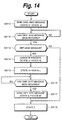
portion; Fig. 14 is a flow chart for explaining the
operation of a main application shown in Fig. 6; Fig.
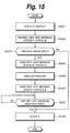
15 is a flow chart for explaining the operation of an
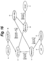
encoding process manager shown in Fig. 6; Fig. 16 is a
schematic diagram for explaining a state transition of
a process portion in the case that an initializing
process is performed when an abnormality takes place;
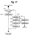
Fig. 17 is a flow chart for explaining an initializing
process performed when an abnormality takes place; Fig.
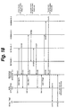
18 is a flow chart for explaining an initializing
process performed when an abnormality takes place; Fig.
19 is a schematic diagram showing an example of another
structure of the music delivery service system
according to the present invention; Fig. 20 is a block
diagram showing an example of the structure of a
terminal unit shown in Fig. 19; and Fig. 21 is a block
diagram showing an example of the functional structure
of the terminal unit shown in Fig. 19.
Best Mode for Carrying Out the Invention
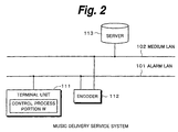
Fig. 2 shows an example of the structure of
the delivery side of a music delivery service system
according to the present invention. In this example,
an alarm LAN 101 and a medium LAN 102 corresponding to
the 100 BASE-TX Ethernet (trademark) are disposed. A
terminal unit 111 and an encoder 112 are connected to
the alarm LAN 101. The encoder 112 and a server 113
are connected to the medium LAN 102.
The terminal unit 111 has a control process
portion W composed of a program that controls the
encoder 112. Under the control of the control process
portion W, the terminal unit 111 communicates with the
encoder 112 through the alarm LAN 101 and causes the
encoder 112 to execute a predetermined encoding process.
The encoder 112 is controlled by the terminal
unit 111. The encoder 112 receives PCM non-compressed
music data such as CD-DA (Compact Disc - Digital Audio)
stored in the server 113 through the medium LAN 102 and
executes the encoding process corresponding to the
ATRAC 1 standard or MPEG 1 audio layer 3 (so-called
MP3) standard. In addition, the encoder 112 transfers
PCM compressed music data that has been encoded to the
server 113 through the medium LAN 102 corresponding to
for example file transfer base (file transfer protocol:
ftp).
The server 113 records PCM non-compressed
music data and supplies the data to the encoder 112.
In addition, the server 113 records PCM compressed
music data received from the encoder 112 and when
necessary delivers the data to a user (reception side)
of the music delivery service.
Thus, since the alarm LAN 101 that transfers
control data and the medium LAN 102 that transfers
music data are independently disposed, the encoding
process and the music data delivering process can be
more effectively performed.
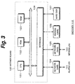
Fig. 3 shows an example of the structure of
the encoder 112. A CPU (Central Processing Unit) 121
expands for example an encoding process program stored
in a ROM (Read Only Memory) 122 or a hard disk 127 to a
RAM (Random Access Memory) 123 and executes the
encoding process corresponding to the encoding process
program. The RAM 123 temporarily stores data necessary
for executing for example the encoding process. In the
RAM 123, a necessary data buffer area is allocated.
A network card 124 is connected to the alarm
LAN 101. The network card 124 receives and transmits
control data through the alarm LAN 101.
A network card 125 is connected to the medium
LAN 102. The network card 125 receives PCM non-compressed
music data from the server 113 through the
medium LAN 102 and transmits PCM compressed music data
that has been encoded by an encode card 126 to the
server 113.
The encode card 126 receives PCM non-compressed
music data from the network card 125 and
encodes the PCM non-compressed music data corresponding
to the ATRAC 1 based encoding process or the MPEG 1
based encoding process.
The hard disk 127 stores programs executed by
the CPU 121. In addition, the hard disk 127 stores the
PCM non-compressed music data received from the network
card 125 and the PCM compressed music data encoded by
the encode card 126.
In this example, since music data is
transferred to the medium LAN 102 that is an Ethernet
LAN, PCM non-compressed music data is not encoded on
real time basis. PCM non-compressed music data that is
supplied from the server 113 is stored to the hard disk
127. At a proper timing, the PCM non-compressed music
data is supplied to the encode card 126. As a result,
the PCM non-compressed music data is encoded by the
encode card 126. Thereafter, the PCM compressed music
data that has been encoded is stored to the hard disk
127. Since the hard disk 127 is used as a temporary
buffer, PCM non-compressed music data is properly
encoded.
An interface 128 is disposed among the
network card 124, the network card 125, the encode card
126, the hard disk 127, and the CPU 121. The interface
128 executes an interfacing process.
The CPU 121, the ROM 122, the RAM 123, and
the interface 128 are disposed on one mother board 120.
The music delivery service system is
controlled by a real time OS (Operating System). The
real time OS is a multitask OS that simultaneously
operates a plurality of tasks (processes). By a non-multitask
OS, while a particular process is being
executed, even if another event (namely, an external
request) takes place, the event handler for the
external request may not immediately get started. In
contrast, by the real time OS, it is assured that in a
predetermined time period, a relevant event handler
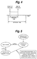
gets started. In other words, as shown in Fig. 4, a
process that is started in predetermined time
corresponding to a clock (the predetermined time is
referred to as survival time) is completed in the
survival time.
Fig. 5 schematically shows the basic concept
of the real time OS. When each process portion is
generated, it is managed so that it successively
advances to one of three states that are operation
state, wait state, and operation enable state. Each
process portion is managed with a flag. When each
process portion advances from the operation state to
the wait state, a command waitFlag that causes the
process portion to wait for a flag is generated. When
each process portion advances form the wait state to
the operation enable state, a command setFlag that sets
a value to a flag is generated.
A plurality of process portions can take
place at the same time. Priority is assigned to each
of the plurality of process portions. The real time OS
passes an execution right to a process portion assigned
the highest priority in process portions that are in
the operation enable state.
When an event takes place, the real time OS
can quickly the current process portion to another
process portion assigned the highest priority in
process portions that are in the operation state.
Fig. 6 shows an example of the functional
structure of the encoder 112 (namely, an example of the
structure of an encoding process program). The
encoding process program is composed of three process
portions (each of which has an executable program and a
data area necessary for executing the program) and
three capsules (elements denoted by dual line boxes).
The three processes are a capsule manager 151, an
encoding process controlling application 152, and a
main application 153. The three capsules are a control
data input - output capsule 154, a music data input -
output capsule 155, and an encoding process capsule 156.
Each capsule is composed of a plurality of process
portions that are formed as a block (capsulated). In
Fig. 6, an element denoted by a solid line box is a
process portion.
The capsule manager 151 controls the encoding
process controlling application 152, the control data
input - output capsule 154, the music data input -
output capsule 155, and the encoding process capsule
156 through the main application 153.
The encoding process controlling application
152 communicates with the main application 153,
receives a command from for example the capsule manager
151, and controls the control data input - output
capsule 154 corresponding to the command. The main
application 153 directly communicates with the capsule
manager 151 and controls the music data input - output
capsule 155 and the encoding process capsule 156
corresponding to a command received from the capsule
manager 151.
The control data input - output capsule 154
is managed by an encoding process controlling manger
161. The encoding process controlling manger 161
generates and erases a network card input I/F process
portion 162 (hereinafter referred to as network card
input I/F, this applied to other process portions), a
network card output I/F 163, and a network card driver
(process portion) 164 corresponding to a command
received from the encoding process controlling
application 152.
The network card input I/F 162 receives
control data (command) from the control process portion
W of the terminal unit 111 through the network card 124
and the network card driver 164 and outputs the control
data to the encoding process controlling manger 161.
The network card output I/F 163 receives control data
(message) from the main application 153 through the
encoding process controlling application 152 and the
encoding process controlling manger 161 and outputs the
control data to the network card driver 164.
The network card driver 164 executes an input
- output interfacing process for the network card 124,
receives control data (command) transferred on the
alarm LAN 101, and outputs the control data to the
network card input I/F 162. In addition, the network
card driver 164 receives control data (message) from
the network card output I/F 163 and outputs the control
data to the network card 124.
The music data input - output capsule 155 is
managed by a data input - output manager 171. The data
input - output manager 171 generates and deletes a
network card input - output I/F 172 (process portion)
and a network card driver 173 (process portion)
corresponding to a command received from the main
application 153.
The network card input - output I/F 172
receives PCM non-compressed music data from the server
113 through the network card 125 and the network card
driver 173 and outputs the PCM non-compressed music
data to the data input - output manager 171. In
addition, the network card input - output I/F 172
receives PCM compressed music data from the data input
- output manager 171 and outputs the PCM compressed
music data to the network card driver 173.
The network card driver 173 executes an input
- output interfacing process for the network card 125,
receives PCM non-compressed music data transferred on
the medium LAN 102, and outputs the PCM non-compressed
music data to the network card input - output I/F 172.
In addition, the network card driver 173 receives PCM
compressed music data from the network card input -
output I/F 172 and outputs the PCM compressed music
data to the network card 125.
The encoding process capsule 156 is managed
by an encoding process manager 181. The encoding
process manager 181 generates and deletes an encode
engine input - output I/F 182, an encode engine input -
output I/F 183, an encode engine 184, an encode card
input - output I/F 185, an encode card input - output
I/F 186, and an encode card driver 187 (all are process
portions). In addition, the encoding process manager
181 performs an encoding process type determining
process for determining whether the encoding process is
performed by software (encode engine 184) or hardware
(encode card 126). In addition, the encoding process
manager 181 performs an encoding process type
determining process for determining whether the
encoding process is performed corresponding to the
ATRAC 1 based encoding process or the MPEG 1 based
encoding process.
The encode engine input - output I/F 182
receives PCM non-compressed music data that is encoded
corresponding to the ATRAC 1 based encoding process
from the encoding process manager 181 and outputs the
PCM non-compressed music data to the encode engine 184.
In addition, the encode engine input - output I/F 182
receives PCM compressed music data that has been
encoded corresponding to the ATRAC 1 based encoding
process from the encode engine 184 and outputs the PCM
compressed music data to the encoding process manager
181.
The encode engine input - output I/F 183
receives PCM non-compressed music data that is encoded
corresponding to the MPEG 1 based encoding process from
the encoding process manager 181 and outputs the PCM
non-compressed music data to the encode engine 184. In
addition, the encode engine input - output I/F 183
receives PCM compressed music data that has been
encoded corresponding to the MPEG 1 based encoding
process from the encode engine 184 and outputs the PCM
compressed music data to the encoding process manager
181.
The encode engine 184 executes the ATRAC 1
based encoding process by software or the MPEG 1 based
encoding process by software corresponding to control
data supplied from the encode engine input - output I/F
182 and the encode engine input - output I/F 183.
The encode card input - output I/F 185
receives PCM non-compressed music data that is encoded
corresponding to the ATRAC 1 based encoding process
from the encoding process manager 181 and outputs the
PCM non-compressed music data to the encode card driver
187. In addition, the encode card input - output I/F
185 receives PCM compressed music data that has been
encoded corresponding to the ATRAC 1 based encoding
process from the encode card driver 187 and outputs the
PCM compressed music data to the encoding process
manager 181.
The encode card input - output I/F 186
receives PCM non-compressed music data that is encoded
corresponding to the MPEG 1 based encoding process from
the encoding process manager 181 and outputs the PCM
non-compressed music data to the encode card driver 187.
In addition, the encode card input - output I/F 186
receives PCM compressed music data that has been
encoded corresponding to the MPEG 1 based encoding
process from the encode card driver 187 and outputs the
PCM compressed music data to the encoding process
manager 181.
The encode card driver 187 executes an input
- output interfacing process for the encode card 126,
receives PCM non-compressed music data from the encode
card input - output I/F 185 and the encode card input -
output I/F 186, and outputs the PCM non-compressed
music data to the encode card 126. In addition, the
encode card driver 187 receives PCM compressed music
data that has been encoded from the encode card 126,
and outputs the PCM compressed music data to the encode
card input - output I/F 185 and the encode card input -
output I/F 186. When the encode card 126 as a hardware
device performs the ATRAC 1 based encoding process, it
is substituted with a device having a relevant function.
When the encode card 126 performs the MPEG 1 based
encoding process, it is substituted with a device
having a relevant function.
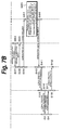
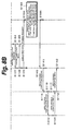
Next, with reference to a flow chart shown in
Fig. 7, the processes performed by the individual
process portions in the case that the ATRAC 1 based
encoding process is performed will be described.
When the power of the encoder 112 is turned
on, the real time OS generates the capsule manager 151.
The capsule manager 151 causes the main application 153
to generate the music data input - output capsule 155
and the encoding process capsule 156. In addition, the
capsule manager 151 causes the encoding process
controlling application 152 to generate the control
data input - output capsule 154.
When the control process portion W of the
terminal unit 111 sends a command for the ATRAC 1 based
encoding process to the network card 124 of the encoder
112 through the alarm LAN 101, the command is supplied
from the network card driver 164 of the control data
input - output capsule 154 to the encoding process
controlling manger 161 through the network card input
I/F 162. When the encoding process controlling manger
161 receives the command, the encoding process
controlling manger 161 requests the encoding process
controlling application 152 to start the ATRAC 1 based
encoding process at step S1.
The encoding process controlling application
152 receives the request message from the encoding
process controlling manger 161 at step S11. The
request message contains code information that
represents an encoding process type and an a portion
that executes the encoding process. In this example,
the encoding process type is the ATRAC 1 based encoding
process and the portion that executes the encoding
process is a hardware device (encode card 126).
When the encoding process controlling
application 152 receives the request message from the
encoding process controlling manger 161, the encoding
process controlling application 152 requests the main
application 153 to permit the ATRAC 1 based encoding
process at step S12.
When the main application 153 receives the
request message from the encoding process controlling
application 152 at step S31, the main application 153
determines whether or not the process corresponding to
the request message can be executed. When the process
cannot be executed, the main application 153 sends a
reply message that represents that the process cannot
be executed to the encoding process controlling
application 152. When the encoding process controlling
application 152 receives the reply message, the
encoding process controlling application 152 sends the
reply message to the encoding process controlling
manger 161. The encoding process controlling manger
161 sends the reply message to the control process
portion W of the terminal unit 111 through the encoding
process controlling manger 161, the network card output
I/F 163, the network card driver 164, and the network
card 124.
In the example shown in Fig. 7, the main
application 153 determines that the ATRAC 1 based
encoding process can be executed and sends a relevant
permission reply message to the encoding process
controlling application 152 at step S32.
When the encoding process controlling
application 152 receives the permission reply message
from the main application 153 at step S13, the encoding
process controlling application 152 outputs a reply
message that represents the start of the ATRAC 1 based
encoding process to the encoding process controlling
manger 161 at step S14. The encoding process
controlling manger 161 receives the reply message at
step S2. In the above-described manner, the encoding
process controlling manger 161 sends the reply message
to the control process portion W.
The main application 153 outputs a permission
reply message for the ATRAC 1 based encoding process to
the encoding process controlling application 152 at
step S32. Thereafter, the main application 153
requests the data input - output manager 171 of the
music data input - output capsule 155 to acquire object
data that is encoded (namely, outputs an object data
acquisition request message). The object data
acquisition request message contains the address of the
object data in the storing portion, the data amount
thereof, and so forth.
When the data input - output manager 171
receives the request message from the main application
153 at step S81, the data input - output manager 171
executes a process for acquiring the object data that
is encoded from the designated address at step S82.
When the object data is stored in the hard
disk 127, the data input - output manager 171 accesses
the hard disk 127 through the network card input -
output I/F 172, the network card driver 173, and the
network card 125 and acquires PCM non-compressed music
data for the designated amount from the designated
address.
When the object data is recorded on a CD-R
(not shown) or the like, the data input - output
manager 171 accesses it and acquires the object data
therefrom. When the object data is recorded in the
server 113, the data input - output manager 171
accesses the server 113 through the alarm LAN 101 and
receives the object data from the server 113 through
the medium LAN 102. The acquired PCM non-compressed
music data is temporarily stored to a buffer area of
the RAM 123.
When the PCM non-compressed music data is
acquired in such a manner, the data input - output
manager 171 sends an object data acquisition completion
reply message to the main application 153 at step S83.
When the main application 153 receives the
object data acquisition completion reply message from
the data input - output manager 171 at step S34, the
main application 153 requests the encoding process
manager 181 to start encoding the object data at step
S35. This request message contains information that
represents that the encoding process type is the ATRAC
1 based encoding process and the encoding process
portion is the encode card 126.
When the encoding process manager 181
receives the encoding process start request message
from the main application 153 at step S61, the encoding
process manager 181 determines whether or not the
process for the request message can be executed. When
the process for the request message cannot be executed,
the encoding process manager 181 outputs a reply
message that represents that the process for the
request message cannot be executed to the main
application 153. In the example shown in Fig. 7, the
encoding process manager 181 determines that the
encoding process can be executed and outputs a reply
message that represents that the encoding process can
be executed to the main application 153 at step S62.
The main application 153 receives the
encoding process start reply message from the encoding
process manager 181 at step S36. Thus, the main
application 153 knows that the encoding process manager
181 has accepted the process for the request message
sent at step S35.
After the encoding process manager 181
outputs an encoding process start reply message to the
main application 153 at step S62, the encoding process
manager 181 causes the main application 153 to execute
the encoding process at step S63. In reality, the
encoding process manager 181 requests the encode card
126 to execute the ATRAC 1 based encoding process
through the encode card input - output I/F 185 and the
encode card driver 187 corresponding to the encoding
process start request message received from the main
application 153. This request message contains the
address of a buffer of the RAM 123 for the PCM
compressed music data. The encode card 126 reads the
PCM non-compressed music data from the buffer area of
the RAM 123 corresponding to the request message and
executes the ATRAC 1 based encoding process. The
encoded PCM compressed music data is recorded to the
RAM 123.
After the encode card 126 has completed the
encoding process, the encoding process manager 181
sends an encoding process completion message that
represents the encoding process has been completed to
the main application 153 at step S64.
When the main application 153 receives the
encoding process completion message from the encoding
process manager 181 at step S37, the main application
153 sends a encoding process completion reply message
to the encoding process manager 181 at step S38.
The encoding process manager 181 receives the
encoding process completion reply message from the main
application 153 at step S65. Thus, the encoding
process manager 181 acknowledges that the encoding
process completion message has been sent to the main
application 153.
After the main application 153 outputs the
encoding process completion reply message to the
encoding process manager 181 at step S38, the main
application 153 outputs a generated data storing
request message for PCM compressed music data that has
been encoded and generated to the data input - output
manager 171. This request message contains the address
of a medium that stored the data. When the PCM
compressed music data that has been encoded is stored
to the hard disk 127, the request message contains the
address of the hard disk 127.
When the data input - output manager 171
receives the generated data storing request message
from the main application 153 at step S84, the data
input - output manager 171 executes a process for
storing the received data corresponding to the request
message at step S85. In reality, when the request
message represents that the generated data should be
stored to the hard disk 127, the data input - output
manager 171 accesses the hard disk 127 through the
network card input - output I/F 172, the network card
driver 173, and the network card 125 and records the
PCM compressed music data that has been encoded to the
designated address of the hard disk 127.
When the request message represents that the
generated data should be stored to a CD-R, the PCM
compressed music data that has been encoded is stored
to the designated address of the CD-R. When the
request message represents that the generated data
should be stored to the server 113, the PCM compressed
music data that has been encoded is supplied and stored
to the server 113 through the medium LAN 102.
After the PCM compressed music data has been
stored in the above-described manner, the data input -
output manager 171 outputs a generated data storage
completion reply message that represents that the data
has been stored to the main application 153 at step S86.
When the main application 153 receives the
generated data storage completion reply message from
the data input - output manager 171 at step S40, the
main application 153 outputs a completion message that
represents that the ATRAC 1 based encoding process has
been completed to the encoding process controlling
application 152 at step S41.
When the encoding process controlling
application 152 receives the message from the main
application 153 at step S15, the encoding process
controlling application 152 sends a message that
represents that the ATRAC 1 based encoding process has
been completed to the encoding process controlling
manger 161 at step S16.
When the encoding process controlling manger
161 receives the completion message from the encoding
process controlling application 152 at step S3, the
encoding process controlling manger 161 outputs a reply
message corresponding to the completion message to the
encoding process controlling application 152 at step S4.
When the encoding process controlling
application 152 receives the reply message from the
encoding process controlling manger 161 at step S17,
the encoding process controlling application 152 sends
an ATRAC 1 based encoding process completion replay
message to the main application 153 at step S18.
The main application 153 receives the
completion reply message from the encoding process
controlling application 152 at step S42.
Fig. 8 shows the MPEG 1 based encoding
process. Steps S101 to S142 shown in Fig. 8 are
basically the same as steps S1 to S42 of the ATRAC 1
based encoding process shown in Fig. 7. However, in
Fig. 8, the encoding process type is the MPEG 1 based
encoding process rather than the ATRAC 1 based encoding
process. Thus, in the object data acquisition process
at step S182 shown in Fig. 8 corresponding to step S82
shown in Fig. 7, the data sending amount and the data
sending timing in the format corresponding to the ATRAC
1 based encoding process are changed to those
corresponding to the MPEG 1 based encoding process.
In addition, in the process at step S163
shown in Fig. 8 corresponding to the process at step
S63 of the ATRAC 1 based encoding process shown in Fig.
7, the MPEG 1 based encoding process is executed rather
than the ATRAC 1 based encoding process. Of course,
since the ATRAC 1 based encoding process is different
from the MPEG 1 based encoding process, for example,
different encoding data unit, different sending timing,
and different error correction code are used.
This applies to the process at step S185
shown in Fig. 8 corresponding to the process at step
S85 shown in Fig. 7.
However, all processes required due to the
different encoding method are executed by each process
portion such as the capsule manager 151 of the encoding
process capsule 156 and each process portion such as
the data input - output manager 171 of the music data
input - output capsule 155. Thus, the main application
153, the encoding process controlling application 152,
and so forth do not need to precisely recognize the
differences between the ATRAC 1 based encoding process
and the MPEG 1 based encoding process.
In other words, from the view point of the
main application 153, the details of the data acquiring
process and the data storing process executed by the
data input - output manager 171 of the music data input
- output capsule 155 and the encoding process executed
by the encoding process manager 181 of the encoding
process capsule 156 are concealed.
For example, when the data input - output
manager 171 acquires data from the hard disk 127, the
data input - output manager 171 uses ATA (AD (Advanced
Technology) Attachment) command. However, when the
data input - output manager 171 acquires data from the
server 113 on the network, the data input - output
manager 171 uses FTP (File Transfer Protocol) of TCP/IP
(Transmission Control Protocol / Internet Protocol) or
HTTP (Hyper Text Transport Protocol).
When the data input - output manager 171
acquires data from a CD-R, the data input - output
manager 171 uses the SCSI (Small Computer System
Interface) interface. When the data input - output
manager 171 acquires data from a CD-R, the data input -
output manager 171 uses the ATAPI (AT Attachment Packet
Interface).
When the ATRAC type encoding process is
performed at high speed, the process is performed
through the ATRAC encoder driver of the encode card
driver 187. When the MPEG format encoding process is
performed at high speed, the process is performed
through the MPEG encoder driver of the encode card
driver 187.
The encoding process capsule 156 performs
processes using various hardware driver protocols.
However, the main application 153 requires only three
simple sequences that are a data acquisition request,
an encoding process start request, and a data storing
request.
Thus, the encoding process capsule 156 and
the music data input - output capsule 155 conceal these
protocols and data acquiring method against the main
application 153.
As a result, the main application 153 and the
encoding process controlling application 152 need to
only determine what encoding process type is used and
whether the encoding process is executed by software or
hardware. Thus, even if the encoding process type is
changed or extended, it is not necessary to change the
main application 153 and the encoding process
controlling application 152. If necessary, their
changes are small.
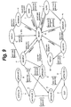
The program for the encoding process of the
encoder 112 is structured as described above. The
process portions (elements denoted by sold line boxes)
shown in Fig. 6 change their states corresponding to a
state transition chart shown in Fig. 9 and execute
their processes.
The states shown in Fig. 9 compose the
operation states shown in Fig. 5.
The state transition chart shown in Fig. 9
show 12 types of states that are execute (EXECUTE),
initialize 0 (INITIALIZE 0), initialize 1 (INITIALIZE
1), initialize 2 (INITIALIZE 2), terminate 1 (TERMINATE
1), terminate 0 (TERMINATE 0), exit (EXIT), receive
(RECEIVE), reply (REPLY), manage (MANAGE), send (SEND),
and ready (READY).
Next, with reference to a flow chart shown
Fig. 10, the state transition in the case that each
process portion is normal will be described.
When the power of the terminal unit is turned
on, the real time OS gets started and generates a
process portion. The process portion advances to the
execute state (EXECUTE) A at step S201.
Thereafter, the process portion advances to
the initialize 0 state (INITIALIZE 0) B at step S202.
In the initialize 0 state (INITIALIZE 0) B, the capsule
(module) registering process is executed. In reality,
a first buffer used to exchange data with the hardware
device is allocated. Thereafter, the first buffer is
initialized (for example 0s are written to the first
buffer). Thereafter, the device is opened. Next, it
is determined whether or not the device is normal.
This process is performed once time when the power of
the terminal unit is turned on.
The process portion advances from the
initialize 0 state (INITIALIZE 0) B to the initialize 1
state (INITIALIZE 1) C at step S203. In initialize 1
state (INITIALIZE 1) C, the capsule resource allocating
process is executed. Thus, a second buffer used to
exchange data with the main application 153 is
allocated. Thereafter, the second buffer is
initialized. Next, a register is initialized.
The process portion advances from the
initialize 1 state (INITIALIZE 1) C to the initialize 2
state (INITIALIZE 2) D at step S204. In the initialize
2 state (INITIALIZE 2) D, an initializing process for
the capsules including the device is executed. When
the initializing process is executed, the first buffer
is initialized again (at that point, the allocating
process is not performed).
Thereafter, the process portion advances from
the initialize 2 state (INITIALIZE 2) D to the ready
state (READY) E at step S205.
Each process portion advances to one of the
states E, F, G, H, I, J, K, L, and M shown in Fig. 9 at
step S205. In other words, each process portion
determines whether or not a process request message for
a completion request has been received at step S206.
When a process request message other than the
completion request has been received, the flow returns
to step S205. At step S205, each process portion
advances to a relevant state.
When the process portion is in one of the
states E to M, if the determined result at step S206
represents that a process request message of a
completion request has been received, the flow advances
to step S207. The process portion advances to the
terminate 1 state (TERMINATE 1) N at step S207. In the
terminate 1 state N, an unallocating process for the
second buffer is performed. Thereafter, the flow
advances to step S208. The process portion advances to
the terminate 0 state (TERMINATE 0) O at step S208. In
the terminate 0 state (TERMINATE 0) O, the first buffer
is unallocated. In addition, the device is closed.
Thereafter, the flow advances to step S209.
The process portion advances to the exit state (EXIT) P
at step S209. In the exit state P, the real time OS is
stopped and the power of the terminal unit is turned
off.
Each process portion exchanges an inter
process portion communication message with other
process portions. In a particular state, each process
portion advances to another state denoted by an arrow
mark shown in Fig. 9.
Fig. 11 shows the format of an inter process
portion communication message. As shown in Fig. 11A,
an inter process portion communication message is
composed of a header and an extended portion. Data is
written to the header and the extended portion of the
inter process portion communication message
corresponding to the FTP (File Transfer Protocol)
format. As shown in Fig. 11C, "unsigned short type;"
of the header contains message type (denoted by MSGT
(Message Type), function type (denoted by FNCT
(Function Type)), message number (denoted by MSGN
(Message number)), and function number (denoted by FNCN
(Function Number)).
MSGT contains data of one of 00 to 11
assigned corresponding to a requested process of
interrupt, send, receive, or reply.
| <Process> | <Data> |
| Interrupt (INT (INTERRUPT)) | 008 |
| Send (SND (SEND)) | 01B |
| Receive (RCV (RECEIVE)) | 10B |
| Reply (RPY (REPLY)) | 11B |
MSGN contains one of data assigned
corresponding to a requested process.
| <Process> | <Data> |
| Quit (QUT (QUIT)) | 001B |
| Reset (RST (RESET)) | 010B |
| Terminate (TRM (TERMINATE)) | 011B |
| Request (REQ (REQUEST)) | 100B |
| Notify (NTF (NOTIFY)) | 101B |
| Refuse (RFS (REFUSE)) | 110B |
| Acknowledgement (ACK (ACKNOWLEDGE)) | 111B |
FNCT and FNCN contain data corresponding to a
requested process.
| <FNCT> | <FNCN> |
| Encode | ATRAC 1 based encoding process |
| | MPEG |
| 1 based encoding process |
| File transfer | put |
| | get |
"pid_t src_pid" of the header contains the ID
of the source process portion of an inter process
portion communication message. "pid_t dst_pid" of the
header contains the ID of the destination process
portion of an inter process portion communication
message.
The extended portion of an inter process
portion communication message contains data of the
stored location of encoded PCM non-compressed music
data (for example, a memory address of the hard disk
127) and data of the stored location of encoded PCM
compressed music data.
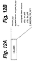
An inter process portion communication
message shown in Fig. 12 is composed of only the header
of the inter process portion communication message
shown in Fig. 11.
Next, the state transition from the state E
to the state M shown in Fig. 9 at steps S205 and S206
shown in Fig. 10 will be described. In this example,
the case that the main application 153 requests the
encoding process manager 181 to perform the ATRAC 1
based encoding process corresponding to a request
message received from the terminal unit 111 (control
process portion W) will be described.
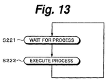
Each process is programmed as shown in Fig.
13. In Fig. 13, each process portion starts from a
process waiting state at step S221. Thereafter, the
flow advances to step S222. The process portion
executes a predetermined process at step S222. When
the process portion completes the process, the flow
returns to step S221. Thus, the state transition of
each process portion is pre-defined. In other words,
the direction of the state transition is not defined in
each state. Thus, the states of each process portion
advance corresponding to routes represented by arrow
marks shown in Fig. 9.
First of all, the state transition of the
main application 153 will be described with reference
to a flow chart shown in Fig. 14. It is assumed that
the main application 153 has advanced to the ready
state (READY) E at steps S201 to S205 shown in Fig. 10.
The main application 153 sends an inter
process portion communication message having a header
containing MSGT = SND, MSGN = REQ, FNCT = data
representing encode, and FNCN = ATRAC 1 based encoding
process (hereinafter, an inter process portion
communication message having a header containing MSGT =
SND and MSGN = REQ is denoted by (SND, REQ) message;
this notation applies to other inter process portion
communication messages) to the encoding process manager
181. Thereafter, the main application 153 advances
from the ready state (READY) E to the send state (SEND)
J.
The header of the (SND, REQ) message has
"pid_t src_pid" containing the ID of the main
application 153 as the source process portion and
"pid_t dst_pid" containing the ID of the encoding
process manager 181 as the destination process portion.
In addition, the (SND, REQ) message has the extended
portion as shown in Fig. 11. The extended portion
contains the memory address of the hard disk 127 for
encoded PCM non-compressed music data and the memory
address of the hard disk 127 for encoded PCM compressed
music data.
In Fig. 9, messages in brackets represent
receive messages, whereas messages without brackets
represent send messages.
At that point, the main application 153
starts up a built-in timer t.
Thereafter, the main application 153 waits
until an inter process portion communication message
having the header containing MSGT = RPY (this message
is denoted by (RPY, XXX) message) corresponding to the
(SND, REQ) message sent at step S311 is received from
the encoding process manager 181. When the main
application 153 has received the (RPY, XXX) message
from the encoding process manager 181, the flow
advances to step S313. The (RPY, XXX) message has a
structure shown in Fig. 12. The (RPY, XXX) message has
a structure shown in Fig. 12. In other words, the (RPY,
XXX) message is composed of only a header.
The main application 153 determines whether
or not the (RPY, XXX) message received at step S312 is
a (RPY, ACK) message (containing MSGT = RPY and MSGN =
ACK) at step S313. When the determined result at step
S313 represents that the (RPY, XXX) message is a (RPY,
ACK) message, the flow advances to step S314. As in
this example, when the encoding process manager 181
receives a request message for the encoding process, if
the encoding process can be performed, the encoding
process manager 181 sends the (RPY, ACK) message to the
main application 153.
The main application 153 advances from the
send state (SEND) J to the manage state (MANAGE) K at
step S314. In the manage state (MANAGE) K, the main
application 153 executes a predetermined process.
However, in this case, the main application 153 does
not execute any process. In the manage state (MANAGE)
K, each process portion can execute a predetermined
process when necessary.
The main application 153 sends an encoding
process completion waiting (RCV, REQ) message to the
encoding process manager 181 at step S315. At that
point, the main application 153 advances from the
manage state (MANAGE) K to the receive state (RECEIVE)
L. The main application 153 waits until a (SND, NTF)
message (representing that the encoding process
completion waiting message has been received) is
received from the encoding process manager 181 at step
S316. When the main application 153 receives the (SND,
NTF) message, the flow advances to step S317.
The main application 153 advances from the
receive state (RECEIVE) L to the reply state (REPLY) M
at step S317. In the reply state (REPLY) M, the main
application 153 sends a (RPY, NTF) message as a reply
message of the (SND, NTF) message to the encoding
process manager 181 at step S318. Thereafter, the flow
advances to step S318. The main application 153
advances from the reply state (REPLY) M to the ready
state (READY) E at step S318 and completes the process.
When the encoding process manager 181
receives a (SND, REQ) message as an encoding process
request message from the main application 153, if the
encoding process cannot be executed due to any reason,
the encoding process manager 181 sends a (RPY, NTF)
message that represents that the encoding process
cannot be executed. In this case, the encoding process
manager 181 determines that the received (RPY, XXX)
message is not the (RPY, ACK) message at step S313. As
a result, the flow advances to step S318, skipping
steps S314 to S317. The main application 153 advances
from the send state (SEND) J to the ready state (READY)
E and completes the process.
In the send state (SEND) J, the manage state
(MANAGE) K, and the receive state (RECEIVE) L, the main
application 153 determines whether or not the measured
time of the timer t that has been started at step S311
exceeds predetermined time. When the determined result
represents that the measured time does not exceed the
predetermined time, the main application 153 executes
the above-described process. In contrast, when the
determined result represents that the measured time of
the timer t exceeds the predetermined time (namely, the
timer t has timed out), the main application 153
advances to the ready state (READY) E and completes the
process.
Next, the state transition of the encoding
process manager 181 in such a case will be described
with reference to a flow chart shown in Fig. 15. The
encoding process manager 181 sends a (RCV, REQ) message
that represents the encoding process manager 181 waits
for an encoding process request to the main application
153 at step S321. The encoding process manager 181
advances from the ready state (READY) E to the receive
state (RECEIVE) F. At that point, the encoding process
manager 181 starts up the built-in timer t.
When the encoding process manager 181
receives a (SND, REQ) message as an encoding process
request message from the main application 153 (this
message is sent at step S311 shown in Fig. 14) at step
S322, the encoding process manager 181 determines
whether or not the requested encoding process can be
executed at step S323. When the requested encoding
process can be executed, the flow advances to step S324.
The encoding process manager 181 advances from the
receive state (RECEIVE) F to the reply state (REPLY) G
at step S324.
The encoding process manager 181 sends a (RPY,
ACK) message as an encoding process acceptance reply
message corresponding to the (SND, REQ) message as an
encoding process request message received from the main
application 153 to the main application 153 at step
S324. The encoding process manager 181 advances to the
manage state (MANAGE) H at step S324.
The encoding process manager 181 controls the
encode card 126 through the encode card input - output
I/F 185 and the encode card driver 187 and executes the
requested ATRAC 1 based encoding process in the manage
state (MANAGE) H at step S325.
The capsule manager 151 decides the priority
and the schedule algorithm of each capsule of the
control data input - output capsule 154, the music data
input - output capsule 155, and the encoding process
capsule 156 and each process of each capsule.
When the encoding process for PCM non-compressed
music data is started, higher priority is
assigned to the encoding process capsule 156 than each
of the control data input - output capsule 154 and the
music data input - output capsule 155. When the ATRAC
1 based encoding process is executed, the highest
priority is assigned to the encoding process manager
181 of the encoding process capsule 156. The next
highest priority is assigned to the encode engine input
- output I/F 182, the encode engine 184, the encode
card input - output I/F 185, and the encode card driver
187. The lowest priority is assigned to each of the
encode engine input - output I/F 183 and the encode
card input - output I/F 186.
In other words, when the ATRAC 1 based
encoding process is executed, higher priority is
assigned to each of the encode engine input - output
I/F 182 that interfaces with the encode engine 184 for
the input and output of music data encoded
corresponding to the ATRAC 1 based encoding process and
the encode card input - output I/F 185 that interfaces
with the encode card driver 187 for the input and
output of music data encoded corresponding to the ATRAC
1 based encoding process than each of the encode engine
input - output I/F 183 that interfaces with the encode
engine 184 for the input and output of music data
encoded corresponding to the MPEG 1 based encoding
process and the encode card input - output I/F 186 that
interfaces with the encode card driver 187 for the
input and output of music data encoded corresponding to
the MPEG 1 based encoding process.
In addition, even if the ATRAC 1 based
encoding process is executed, when a command for an
encoding process using hardware rather than software is
issued, higher priority is assigned to the encode card
input - output I/F 185 than the encode engine input -
output I/F 182.
The capsule manager 151 supplies the priority
of each capsule and each process portion decided in the
above-described manner to each manager (the encoding
process controlling manger 161, the data input - output
manager 171, and the encoding process manager 181) of
the control data input - output capsule 154, the music
data input - output capsule 155, and the encoding
process capsule 156 through the encoding process
controlling application 152 and the main application
153. Each manager generates process portions
corresponding to the priority of process portions and
cause them to executes their processes.
For example, when the ATRAC 1 based encoding
process is executed, the encoding process manager 181
of the encoding process capsule 156 generates the
encode engine input - output I/F 182, the encode engine
184, the encode card input - output I/F 185, and the
encode card driver 187 and supplies the inter process
portion communication messages to them. The encode
engine input - output I/F 182, the encode engine 184,
the encode card input - output I/F 185, and the encode
card driver 187 send and receive the supplied inter
process portion communication messages to communicable
process portions and execute the encoding process.
Thus, in this example, PCM non-compressed music data is
read from the address of the hard disk 127
corresponding to data contained in the extended portion
of an inter process portion communication message. The
PCM non-compressed music data is encoded corresponding
to the ATRAC 1 based encoding process and stored to the
address of the hard disk 127 corresponding to data
contained in the extended portion of the inter process
portion communication message.
In the example of the process shown in Fig.
15, since the ATRAC 1 based encoding process is
executed by hardware, the encode engine input - output
I/F 182, the encode engine input - output I/F 183, the
encode engine 184, and the encode card input - output
I/F 186 are not generated. Thus, it is not necessary
to allocate a resource for them. The resource can be
used for other process portions.
Returning to Fig. 15, when the encoding
process manager 181 completes the encoding process at
step S325, the encoding process manager 181 advances
from the manage state (MANAGE) H to the send state
(SEND) I at step S326. In the send state (SEND) I, the
encoding process manager 181 sends a (SND, NTF) message
that represents that the encoding process has been
completed to the main application 153.
The encoding process manager 181 waits until
it receives a (RPY, NTF) message (that represents that
the encoding process completion waiting message sent at
step S317 shown in Fig. 14) has been received) from the
main application 153 at step S327. When the encoding
process manager 181 receives the (RPY, NTF) message,
the flow advances to step S328. The encoding process
manager 181 advances from the send state (SEND) I to
the ready state (READY) E and completes the process at
step S328.
In the manage state (MANAGE) H and the send
state (SEND) I, the encoding process manager 181
determines whether or not the measured time of the
timer t started at step S321 exceeds predetermined time.
When the determined result represents that the measured
time does not exceed the predetermined time, the
encoding process manager 181 executes the process as
described above. However, when the determined result
represents that the measured time exceeds the
predetermined time, the encoding process manager 181
advances to the ready state (READY) E and completes the
process.
As was described above, the state of each
process portion advances corresponding to the content
of an inter process portion communication message.
Thus, the main application 153 can cause the encoding
process manager 181 to execute a predetermined encoding
process with a message that represents the stored
location of data that is encoded, the stored location
of encoded PCM compressed music data or the encoding
process type. In other words, the main application 153
does not need to control process portions other than
the encoding process manager 181 of the encoding
process capsule 156 (for example, the main application
153 does not need to control data process and buffer
process) and control data transfer. Thus, even if the
encode card 126 is substituted with another encode card
that has a higher performance than that, when a
relevant encoding process capsule 156 is provided along
with the other encode card, it is not necessary to
restructure the main application 153. Thus, the other
encode card can be used (controlled) as it is.
That applies to the relation between the main
application 153 and the music data input - output
capsule 155 and the relation between the encoding
process controlling application 152 and the control
data input - output capsule 154.
In the above example, the encoder 112
executes the ATRAC 1 based encoding process and the
MPEG 1 based encoding process. In addition, the
encoder 112 can execute an encoding process in another
format such as MP3, an effect function, and so forth.
For example, the encoder 112 may be an
encoder in the format corresponding to the ATRAC3
(Adaptive Transform Acoustic Coding 3) (trademark),
MPEG-2AAC (Advanced Audio Code) (trademark), ODesign
Music Codec (trademark), TwinVO (Transform-Domain
Weighted Interleave Vector Quantization) (trademark),
MS Audio (Microsoft Audio (WMA: Windows Media Audio)
(trademark), Ogg Vorbis (trademark), or the like.
Next, with reference to Fig. 16, an
initializing process in the case that an abnormality
takes place in each state will be described. State Q
shown in Fig. 16 corresponds to the ready state (READY)
E, the receive states (RECEIVE) F and L, the reply
states (REPLY) G and M, the manage states (MANAGE) H
and K, and the send states (SEND) I and J. In other
words, there are three routes as initializing routes in
the case that an interrupt (INTERRUPT) message is
received in each of those states. The first route is
the initialize 2 state (INITIALIZE 2) D and the ready
state (READY) E. The second route is the terminate 1
state (TERMINATE 1) N, the initialize 1 state
(INITIALIZE 1) C, the initialize 2 state (INITIALIZE 2)
D, and the ready state (READY) E. The third route is
the terminate 1 state (TERMINATE 1) N, the terminate 0
state (TERMINATE 0) O, and the exit state (EXIT) P.
Fig. 17 is a flow chart for explaining the
initializing process in the case that an abnormality
takes place. This process gets started when an
interrupt message is received. Each process portion
determines whether or not it has received a (INT, QUT)
message as an interrupt message. When the determined
result represents that the received interrupt message
is a (INT, QUT) message, the flow advances to step S352.
The process portion advances to the initialize 2 state
(INITIALIZE 2) D at step S352. In the state, as in the
case at step S204 shown in Fig. 10, an initializing
process for the first buffer is performed. Thereafter,
the process portion advances to the ready state (READY)
E.
Thus, each process portion does not complete
the process (not advance to the exit state (EXIT) P),
but only initializes the first buffer and advances to
the ready state (READY) E. Thus, an overhead for re-generating
a process portion that has been completed is
not required to perform an encoding process.
In addition, when an abnormality takes place
due to any cause, it can be expected that by
initializing the first buffer, the process can be
restored from the abnormality. The first path of the
process can be completed in shorter time than a second
path of the process (that will be described later).
Thus, the process can be more quickly restored from an
abnormality.
When the determined result at step S351
represents that the interrupt message is not a (INT,
QUT) message, the flow advances to step S353. The
process portion determines whether or not the interrupt
message is a (INT, RST) message at step S353. When the
interrupt message is a (INT, RST) message, the flow
advances to step S354. The process portion advances to
the terminate 1 state (TERMINATE 1) N at step S354. In
this state, the process portion performs an
unallocating process for the second buffer.
Next, the flow advances to step S355. The
process portion advances to the initialize 1 state
(INITIALIZE 1) C at step S355. In this state, as in
the case at step S203 shown in Fig. 10, the process
portion executes processes for allocating the second
buffer, initializing it, and initializing a register.
Thereafter, the flow advances to step S356.
The process portion advances to the initialize 2 state
(INITIALIZE 2) D. In this state, as in the case at
step S352, the process portion executes an initializing
process for the first buffer.
Thereafter, the process portion advances to
the ready state (READY) E.
Thus, in the second path of the initializing
process, since the initializing process are performed
in other states including the states of the first path
of the initializing process, the second path of the
initializing process takes longer time than the first
path of the initializing process. However, the second
path of the initializing process allows the process to
be restored from an abnormality more accurately than
the first path of the initializing process.
When the determined result at step S353
represents that the interrupt message is not a (INT,
RST) message, the interrupt message is a (INT, TRM)
message. Thus, in this case, the flow advances to step
S357. The process portion advances to the terminate 1
state (TERMINATE 1) N at step S357. In the state, as
in the case at step S354, the process portion performs
an unallocating process for the second buffer.
Thereafter, the flow advances to step S358. The
process portion advances to the terminate 0 state
(TERMINATE 0) O at step S358. In this state, the
process portion performs an unallocating process for
the first buffer and a process for closing the device.
Thereafter, the process portion advances to
the exit state (EXIT) P. In this state, the real time
OS stops. Thereafter, the power of the terminal unit
is turned off.
The third path is performed when the process
cannot be restored from an abnormality in the first
path and the second path of the initializing process.
In this case, the real time OS re-starts. A process
for re-generating each process portion is performed.
Thus, the third path of the initializing process takes
longer time than the first path or the second path of
the initializing process. However, the third path of
the initializing process allows the process to be
restored from an abnormality more accurately than the
first path or the second path of the initializing
process.
Fig. 18 shows a time sequence of the first
path, the second path, and the third path of the
initializing process.
For example, when an abnormality takes place,
the main application 153 outputs a (INT, QUT) message
to the encoding process manager 181 at step S411. When
the encoding process manager 181 receives the (INT,
QUT) message, the encoding process manager 181 advances
to the initialize 2 state (INITIALIZE 2) D at step S421.
In the initialize 2 state (INITIALIZE 2) D, the
encoding process manager 181 executes the initializing
process for the first buffer. The encoding process
manager 181 advances to the ready state (READY) E at
step S422. The encoding process manager 181 notifies
the main application 153 whether or not the process has
been restored from an abnormality in the first path of
the initializing process at step S423.
When the process has not been restored from
an abnormality in the first path of the initializing
process, the main application 153 outputs a (INT, RST)
message to the encoding process manager 181 at step
S412. When the encoding process manager 181 receives
the (INT, RST) message from the main application 153,
the encoding process manager 181 advances to the
terminate 1 state (TERMINATE 1) N at step S423. The
encoding process manager 181 performs an unallocating
process for the second buffer at step S424. Thereafter,
the encoding process manager 181 advances to the
initialize 1 state (INITIALIZE 1) C at step S425. In
the initialize 1 state (INITIALIZE 1) C, the encoding
process manager 181 performs an allocating process for
the second buffer, an initializing process for the
second buffer, and an initializing process for a
register.
The encoding process manager 181 advances to
the initialize 2 state (INITIALIZE 2) D at step S426.
In the initialize 2 state (INITIALIZE 2) D, the
encoding process manager 181 executes an initializing
process for the first buffer. The encoding process
manager 181 returns to the ready state (READY) E at
step S427. The encoding process manager 181 notifies
the main application 153 whether or not the process has
been restored from an abnormality in the second path of
the initializing process at step S428.
When the determined result at step S428
represents that the process has not been restored from
an abnormality in the second path of the initializing
process, the main application 153 outputs a (INT, TRM)
message to the encoding process manager 181 at step
S413.
When the encoding process manager 181
receives the (INT, TRM) message from the main
application 153, the encoding process manager 181
advances to the terminate 1 state (TERMINATE 1) N at
step S429. In the terminate 1 state (TERMINATE 1) N,
the encoding process manager 181 performs an
unallocating process for the second buffer. The
encoding process manager 181 advances to the terminate
0 state (TERMINATE 0) O at step S430. In the terminate
0 state (TERMINATE 0) O, the encoding process manager
181 performs an unallocating process for the first
buffer and performs a process for closing the device.
The encoding process manager 181 advances to
the ready state (READY) E at step S431. In the ready
state (READY) E, the encoding process manager 181
notifies the main application 153 whether or not the
process has been restored from an abnormality in the
third path of the initializing process at step S432.
When the determined result represents that
the process has not been restored from an abnormality
in the third path of the initializing process, the main
application 153 requests the real time OS to re-start
at step S414.
The real time OS executes the re-start
process corresponding to the request received from the
main application 153 at step S401.
Thereafter, the real time OS executes a
process for generating the encoding process manager 181
at step S402. Thus, at steps S201 to S205 shown in Fig.
10, the encoding process manager 181 advances to the
ready state (READY) E through the execute state
(EXECUTE) A, the initialize 0 state (INITIALIZE 0) B,
the initialize 1 state (INITIALIZE 1) C, and the
initialize 2 state (INITIALIZE 2) D.
Thus, since there are three paths of the
initializing process that are successively performed in
such a manner that the initializing process is quickly
completed, the encoding process can be more quickly
restored from an abnormality.
In each state other than the receive states
(RECEIVE) F and L, the send states (SEND) I and J, a
message cannot be received. Thus, in each of those
states, even if an abnormality takes place and the
process in the current state cannot be completed, the
process may not be restored from the abnormality. In
addition, in each of the receive states (RECEIVE) F and
L and the send states (SEND) I and J, when an
abnormality takes place, even if a predetermined
message is received, the current state may not advance
to another state. In such a situation, as was
described above, in each state, an interrupt message
can be accepted so that the current process can be
restored from an abnormality.
As was described above, when the header of a
inter process portion communication message contains
MSGT = INT (INTERRUPT), as with a system call SIGNAL of
the UNIX, an exception signal (asynchronous signal)
causes each process portion to advance to the
initialize 1 state (INITIALIZE) (initialize 1 states
(INITIALIZE 1) C and D) and the terminate 1 state
(TERMINATE) (terminate 1 states (TERMINATE 1) N and O).
As a result, when environmental variables are pre-saved,
the current process portion can securely return to the
preceding state.
Fig. 19 shows an example of another structure
of the delivery side of the music delivery service
system according to the present invention. For
simplicity, in Fig. 19, similar portions to those in
Fig. 2 are denoted by similar reference numerals and
their description is omitted.
A terminal unit 200 is connected to an alarm
LAN 101 and a medium LAN 102. The terminal unit 200
receives PCM non-compressed music data from a server
113. The terminal unit 200 encodes the received PCM
non-compressed music data and supplies the encoded data
to the server 113. In other words, the terminal unit
200 also has the function of the encoder 112 along with
the function of the terminal unit 111 shown in Fig. 2.
Fig. 20 shows an example of the structure of
the terminal unit 200. The terminal unit 200 is
composed of for example a computer. An input - output
interface 516 is connected to a CPU 511 through a bus
515. When the user inputs a command from an inputting
portion 518 composed of a keyboard, a mouse, and so
forth to the CPU 511, the CPU 511 loads a program
stored in a ROM 512, a hard disk 514, or a record
medium such as a magnetic disk 531, an optical disc 532,
a magneto-optical disc 533, or a semiconductor memory
534 to a RAM 513 and executes the program with the RAM
513. In addition, when necessary, the CPU 511 outputs
the processed result to a displaying portion 517
composed of for example an LCD through the input -
output interface 516.
The program can be pre-stored to the hard
disk 514 or the ROM 512. The program can be provided
along with the terminal unit 200. In addition, the
program can be provided as a package medium such as the
magnetic disk 531, the optical disc 532, the magneto-optical
disc 533, the semiconductor memory 534, or the
like. Alternatively, the program can be provided from
a satellite, a network, or the like to the hard disk
514 through a communicating portion 519.
It is preferred that the semiconductor memory
534 is a non-volatile memory such as a flash memory.
In addition, it is preferred that the package medium
that contains the semiconductor memory 534 that has a
microcomputer and can authenticate the reading and
writing operations to / from the semiconductor memory
534. The semiconductor memory 534 is for example
memory stick (trademark), SD memory card (trademark),
compact flash (trademark), smart media (trademark),
multimedia card (trademark), micro drive (trademark),
ID format (trademark), or thumb drive (trademark).
Fig. 21 shows an example of the structure of
the program that is loaded to the RAM 513 of the
terminal unit 200 and executed by the CPU 511. The
terminal unit 200 further comprises the control process
portion W of the terminal unit 111 shown in Fig. 2 and
the music data input - output capsule 155 and the
encoding process capsule 156 of the encoder 112 shown
in Fig. 6. In such a structure, the terminal unit 200
can execute the same encoding process as the terminal
unit 111.
In this case, the process performed by the
data input - output manager 171 against the control
process portion W is capsulated as the music data input
- output capsule 155. Likewise, the process executed
by the encoding process manager 181 is capsulated as
the encoding process capsule 156.
In this case, various processes including the
initializing process in the case that an abnormality
takes place are executed corresponding to the above-described
state transition diagram. These processes
are basically the same as those of the above-described
case. Thus, their description is omitted.
In this specification, the steps that
describe the program provided by a medium may be
executed in the given sequential order. Alternatively,
the steps may be executed in parallel or discretely.
Moreover, in this specification, the term
"system" means an apparatus composed of a plurality of
units and / or means.
Industrial Applicability
The present invention is a record medium for
recording a computer controllable program, the program
being disposed between a controlling portion and
hardware, the program controlling the hardware
corresponding to a message received from the
controlling portion, the program comprising a first
process portion for communicating with the controlling
portion, a second process portion for being
communicable with first hardware and second hardware, a
third process portion for communicating with the first
process portion and the second process portion and
executing an interfacing process corresponding to the
first hardware, and a fourth process portion for
communicating with the first process portion and the
second process portion and executing an interfacing
process corresponding to the second hardware, wherein
the first process portion outputs a message to one of
the third process portion and the fourth process
portion corresponding to a message received from the
controlling portion.
Thus, in any case, even if hardware is
changed, it is not necessary to change the controlling
portion. Even in the worst case, the change performed
for the controlling portion is minor. One controlling
portion can be used in common with many hardware
devices.
The present invention is a storage medium for
storing a computer controllable program, disposed
between a controlling portion and hardware, for
controlling the hardware corresponding to a message
received from the controlling portion, the program
containing capsulated process portions, wherein if an
abnormality takes place in each process portion, it is
initialized in one of a first path for initializing a
first buffer for exchanging data with the hardware, a
second path for unallocating a second buffer for
exchanging data with the controlling portion,
allocating the second buffer, initializing the second
buffer, and initializing the first buffer, and a third
path for unallocating the second buffer and
unallocating the first buffer.
Thus, each process portion can be quickly
restored from an abnormality.