EP1143264A2 - GPS receiver having DR sensor signal sampling function - Google Patents
GPS receiver having DR sensor signal sampling function Download PDFInfo
- Publication number
- EP1143264A2 EP1143264A2 EP01302885A EP01302885A EP1143264A2 EP 1143264 A2 EP1143264 A2 EP 1143264A2 EP 01302885 A EP01302885 A EP 01302885A EP 01302885 A EP01302885 A EP 01302885A EP 1143264 A2 EP1143264 A2 EP 1143264A2
- Authority
- EP
- European Patent Office
- Prior art keywords
- gps
- data
- dead
- predetermined cycle
- reckoning
- Prior art date
- Legal status (The legal status is an assumption and is not a legal conclusion. Google has not performed a legal analysis and makes no representation as to the accuracy of the status listed.)
- Granted
Links
Images


Classifications
-
- G—PHYSICS
- G01—MEASURING; TESTING
- G01C—MEASURING DISTANCES, LEVELS OR BEARINGS; SURVEYING; NAVIGATION; GYROSCOPIC INSTRUMENTS; PHOTOGRAMMETRY OR VIDEOGRAMMETRY
- G01C21/00—Navigation; Navigational instruments not provided for in groups G01C1/00 - G01C19/00
- G01C21/26—Navigation; Navigational instruments not provided for in groups G01C1/00 - G01C19/00 specially adapted for navigation in a road network
- G01C21/28—Navigation; Navigational instruments not provided for in groups G01C1/00 - G01C19/00 specially adapted for navigation in a road network with correlation of data from several navigational instruments
-
- G—PHYSICS
- G01—MEASURING; TESTING
- G01S—RADIO DIRECTION-FINDING; RADIO NAVIGATION; DETERMINING DISTANCE OR VELOCITY BY USE OF RADIO WAVES; LOCATING OR PRESENCE-DETECTING BY USE OF THE REFLECTION OR RERADIATION OF RADIO WAVES; ANALOGOUS ARRANGEMENTS USING OTHER WAVES
- G01S19/00—Satellite radio beacon positioning systems; Determining position, velocity or attitude using signals transmitted by such systems
- G01S19/38—Determining a navigation solution using signals transmitted by a satellite radio beacon positioning system
- G01S19/39—Determining a navigation solution using signals transmitted by a satellite radio beacon positioning system the satellite radio beacon positioning system transmitting time-stamped messages, e.g. GPS [Global Positioning System], GLONASS [Global Orbiting Navigation Satellite System] or GALILEO
- G01S19/42—Determining position
- G01S19/48—Determining position by combining or switching between position solutions derived from the satellite radio beacon positioning system and position solutions derived from a further system
- G01S19/49—Determining position by combining or switching between position solutions derived from the satellite radio beacon positioning system and position solutions derived from a further system whereby the further system is an inertial position system, e.g. loosely-coupled
Definitions
- the present invention relates to a GPS receiver used for a navigation system.
- a car navigation system employs a GPS receiver, which has functions of receiving GPS signals, measuring a distance between a GPS satellite and the GPS receiver (i.e., a distance between a GPS satellite and a vehicle which is equipped with the car navigation system), and providing a GPS solution (a GPS position and/or a GPS velocity ).
- the GPS receiver updates the GPS solution and outputs the GPS solution and data related to a GPS measurement as a GPS output message in the predetermined cycle to a host CPU (Central Processing Unit), which functions as a host to the GPS receiver in the car navigation system.
- the host CPU receives the GPS solution and the data related to the GPS measurement and performs various functions, which are required for a car navigation system, such as a dead-reckoning, a map-matching, a route searching, and the like.
- the data related to the GPS measurement includes, for example, error information included in the GPS solution.
- data transmission between the GPS receiver and the host CPU is carried out by serial data transmission.
- a GPS receiver is modularized as a component of a navigation system and is mounted in the navigation systems.
- the host CPU is required to process a plurality of DR (dead-reckoning) sensor signals.
- the host CPU is required to include a plurality of interfaces through which the DR sensor signals are transmitted thereto.
- the host CPU samples the DR sensor signals in a predetermined cycle. Sampling of the DR sensor signals in a predetermined cycle is a significant burden to the host CPU.
- Fig. 1 is a flowchart showing a process in which the host CPU controls the interfaces thereof.
- the interfaces of the host CPU include an I/F1 which is an interface to the GPS receiver, an I/F2 which is an interface for receiving a signal from a gyro sensor, an I/F3 which is an interface for receiving a back signal, an I/F4 which is an interface for receiving a speed pulse signal, and an I/F5 which is an interface to a speed pulse signal filter.
- the back signal indicates whether the vehicle is going ahead or backward.
- the speed pulse signal is transmitted from a velocity sensor mounted on the vehicle and has a frequency corresponding to a velocity of the vehicle.
- the signal from the gyro sensor is filtered and converted to a digital signal. Then, the converted digital signal is input to the I/F2 of the host CPU.
- the speed pulse signal is filtered by the speed pulse signal filter and then input to a counter which counts the number of pulses of the speed pulse signal. The number counted by the counter is read by the host CPU via the I/F4.
- the speed pulse signal filter is a low pass filter of which a cut-off frequency is variable, The cut-off frequency of the speed pulse signal filter varies according to a control signal which is sent from the I/F5 of the host CPU.
- Fig, 1 The process shown in Fig, 1 is called and executed in the host CPU, for example, in a predetermined cycle, e.g., 1 second.
- the host CPU measures time using a timer which is provided in the host CPU to determine if 1/32 second has passed. If 1/32 second has passed (S404: YES), control proceeds to S405. When control proceeds to step S405, the host CPU restarts measuring time from 0 to determine 1/32 second has passed.
- a value of an output voltage of the gyro sensor is transmitted via the I/F2 at S405, and a state of the back signal is transmitted via the I/F3 at S406.
- the number counted by the counter is transmitted via the I/F4 at S407.
- the host CPU takes into account a frequency of the speed pulse signal, the host CPU generates the control signal to optimize the cut-off frequency of the speed pulse signal filter.
- the control signal is transmitted from the I/F 5 of the host CPU to the speed pulse filter.
- the host CPU obtains one GPS output message and obtains 32 pieces of data of the DR sensors in 1 second cycle.
- the number of DR sensors managed by the host CPU should be reduced. In this case, performance in estimating a location of the vehicle as a car navigation system reduces.
- Another object of the present invention is to provide a GPS receiver which has functions required for a car navigation system as well as the GPS measurement function so as to provide a host CPU with information which can reduce a load on the host CPU in a convenient form.
- a navigation system which is provided with a GPS receiver including a GPS measurement system that performs a GPS measurement to obtain a GPS solution, and a processor that estimates a location of a vehicle.
- the processor has an interface to said GPS receiver.
- the GPS receiver further includes at least one dead-reckoning sensor interface that receives at least one dead-reckoning sensor signal, a sampling system that samples the at least one dead-reckoning sensor signal received through the at least one dead-reckoning sensor interface to obtain first data, and an outputting system that outputs the GPS solution and the first data sampled by the sampling system.
- the processor receives the GPS solution and the first data through the interface. In this case, the processor performs a dead-reckoning using the first data to obtain a dead-reckoning solution and estimates the location of the vehicle based on the GPS solution and the dead-reckoning solution.
- the processor can reduce a load of sampling of the at least one dead-reckoning sensor signal.
- the processor is not required to include a plurality of interfaces through which the at least one dead-reckoning sensor signal is transmitted thereto.
- the at least one dead-reckoning sensor signal sampled by the sampling system may include at least one of an output signal of gyro sensor, a back signal, and a speed pulse signal.
- the sampling system samples the at least one dead-reckoning sensor signal a plurality of times.
- the first data includes a plurality of second data.
- the second data represents data sampled at the plurality of times, respectively.
- the GPS measurement system may perform the GPS measurement in a first predetermined cycle, and the sampling system may sample the at least one dead-reckoning sensor signal in a second predetermined cycle.
- the outputting system may output the GPS solution and the first data in a third predetermined cycle.
- the second predetermined cycle is shorter than the first predetermined cycle. Therefore, the first data may include a plurality of pieces of the second data sampled in the second predetermined cycle within a period of the first predetermined cycle.
- the third predetermined cycle is equal to the first predetermined cycle.
- the interface of the processor is a serial interface
- the outputting system of the GPS receiver outputs the first data in a form of serial data.
- the navigation system may include at least one filter that eliminates noise of the at least one dead-reckoning sensor signal.
- characteristics of the at least one filter is variable.
- the processor may vary the characteristics of the at least one filter.
- a GPS receiver which is provided with a GPS measurement system that performs GPS measurement to obtain a GPS solution, at least one dead-reckoning sensor interface that receives at least one dead-reckoning sensor signal, a sampling system that samples the at least one dead-reckoning sensor signal received through the at least one dead-reckoning sensor interface to obtain first data, and an outputting system that outputs the GPS solution and the first data sampled by said sampling system.
- the GPS receiver samples the at least one dead-reckoning sensor signal
- the GPS receiver can provide the sampled data of the at least one dead-reckoning sensor signal for a host CPU. Therefore, the host CPU can reduce a load of processing dead-reckoning sensor signals.
- the at least one dead-reckoning sensor signal may include at least one of an output signal of gyro sensor, a back signal, and a speed pulse signal.
- the sampling system samples the at least one dead-reckoning sensor signal a plurality of times.
- the first data includes a plurality of second data.
- the second data represents data sampled at the plurality of times, respectively.
- the GPS measurement system may perform the GPS measurement in a first predetermined cycle, and the sampling system may sample the at least one dead-reckoning sensor signal in a second predetermined cycle.
- the outputting system may output the GPS solution and the first data in a third predetermined cycle.
- the second predetermined cycle is shorter than the first predetermined cycle. Therefore, the first data may include a plurality of pieces of the second data sampled in the second predetermined cycle within a period of the first predetermined cycle.
- the third predetermined cycle is equal to the first predetermined cycle.
- the outputting system may output the first data in a form of serial data.
- Fig. 2 shows a block diagram of a car navigation system 100 according to an embodiment of the present invention.
- the car navigation system 100 is provided with a host CPU 10 which executes a navigation application program, a GPS receiver 20 which performs a GPS measurement, and a gyro 12 which functions as a DR (Dead-Reckoning) sensor.
- signals of DR sensors i.e., an output signal of the gyro 12, a speed pulse signal 15, and a back signal 17 are used to perform a dead-reckoning.
- the GPS receiver 20 is provided with a down-converter 28 which downconverts a GPS signal caught by a GPS antenna 8 to a lower intermediate frequency.
- the down-converter 28 is connected to a DSP 29 which is a digital signal processor.
- the DSP 29 demodulates the downconverted signal sent from the down-converter 28 under control of a computing unit 22 and obtains navigation data, such as ephemeris, which is sent to the computing unit 22.
- the computing unit 22 in the GPS receiver 20 performs the GPS measurement to obtain a GPS solution, in a predetermined cycle, based on GPS signals which were received by the GPS antenna 8.
- the predetermined cycle is, for example, one second.
- the GPS receiver 20 has an I/F21 which is an interface through which the output signal of the gyro 12 is received, an I/F22 which is an interface through which the back signal 17 is received, and an I/F23 which is an interface through which the speed pulse signal 15 is received.
- the output signal of the gyro 12 has a DC (direct current) voltage corresponding to an angular velocity in a turning direction of a vehicle in which the car navigation system 100 is equipped. Noise of the output signal of the gyro 12 is eliminated by a filter 14. Then, the output signal of the gyro 12 is converted to digital data by an A/D converter 24 in the GPS receiver 20 and input to the computing unit 22. Operation of the A/D converter 24 is controlled by the computing unit 22.
- the speed pulse signal 15 has a frequency corresponding to a velocity of the vehicle. Noise of the speed pulse signal 15 is eliminated by a filter 16, and the noise-eliminated signal is input to a counter 26 which counts the number of pulses of the speed pulse signal 15.
- the computing unit 22 controls operation of the counter 26. A count value of the counter 26 is read by the computing unit 22.
- the filter 16 is a low pass filter of which cut-off frequency is variable.
- the cut-off frequency of the filter 16 varies according to a control signal 19 transmitted from an I/F15 which is an interface of the host CPU 10. Taking into account a frequency of the speed pulse signal 15, the host CPU 10 generates the control signal 19 to optimize the cut-off frequency of the filter 16. Therefore, occurrence of aliasing in sampling the speed pulse signal 15 can be prevented.
- the computing unit 22 samples a digital data of the output voltage of the gyro 12 by controlling the A/D converter 24, a state of the back signal 17, and the count value of the counter 26 at a predetermined sampling rate.
- the predetermined sampling rate in the computing unit 22 is, for example, 60 Hz.
- the computing unit 22 sends the sampled data of the DR sensors (i.e., the digital data of the output voltage of the gyro 12, the state of the back signal 17, and the count value of the counter 26) together with a GPS solution and another information related to the GPS measurement, such as error information included in the GPS solution, to the host CPU 10 as a GPS output message in a form of serial data.
- the GPS output message is outputted every time the GPS solution is calculated in a cycle of one second.
- the host CPU 10 receives the GPS output message and estimates a location of the vehicle based on the GPS solution, a result of the dead-reckoning (a DR solution), and the error information included in the GPS solution.
- a DR solution a result of the dead-reckoning
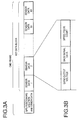
- Fig. 3A shows a data structure of a frame of the GPS output message sent from the computing unit 22 to the host CPU 10.
- a GPS solution and another information related to the GPS measurement are included.
- a first data block which has a plurality of pieces of the sampled data of DR sensors sampled at the sampling rate of 60 Hz within the predetermined cycle of the GPS measurement (i.e., 1 second), is included.
- 60 pieces of the sampled data of the DR sensors i.e., sensor data 1 to sensor data 60
- Fig. 3B shows a data structure of the sampled data of the DR sensors. As shown in Fig 3B, each sampled data of the DR sensors includes the output voltage of the gyro 12, the state of the back signal 17, and the count value of the counter 26.
- the host CPU 10 receives the frame of the GPS output message shown in Fig. 3A through an I/F11 which is a serial interface thereof.
- Fig. 4 is a flowchart showing a process in which the host CPU 10 controls the I/F11 and the I/F15. The process shown in Fig. 4 is called and executed, for example, in a cycle of one second.
- the host CPU 10 first receives the GPS output message through the I/F11 from the GPS receiver 20 (S301). Next, the host CPU 10 obtains the GPS solution, another information related to the GPS measurement, the output voltage of the gyro 12, the count value of the counter 26, and the state of back signal 17 from the GPS output message (S302).
- step S303 according to a frequency of the speed pulse signal 15 determined based on a rate of increase of the count vale of the counter 26, the control signal 19 to optimize the cut-off frequency of the filter 16 is generated. Then, the control signal 19 is sent from the I/F15 to the filter 16 (S304).
- the GPS receiver 20 samples data of DR sensors at a predetermined sampling rate (60Hz) which is faster than a rate at which a GPS solution is obtained (1Hz). Therefore, the host CPU 10 can obtain a plurality of pieces of data of the DR sensors together with a GPS solution by only managing a single serial I/O interface (i.e., I/F11) thereof. That is, the host CPU 10 is not required to manage a plurality of interfaces to obtain a plurality of pieces of data of the DR sensors.
- a single serial I/O interface i.e., I/F11
- a GPS receiver can provide a car navigation system that exhibits high performance without employing a host CPU which has high performance and specialized particularly for car navigation systems.
- the GPS receiver samples a single DR sensor signal (e.g., the speed pulse signal), it is also possible to enhance performance in estimating a location of the vehicle as a car navigation system without increasing a load on the host CPU.
- a single DR sensor signal e.g., the speed pulse signal
- the present invention is not limited to the embodiment described above.
Landscapes
- Engineering & Computer Science (AREA)
- Radar, Positioning & Navigation (AREA)
- Remote Sensing (AREA)
- Physics & Mathematics (AREA)
- General Physics & Mathematics (AREA)
- Automation & Control Theory (AREA)
- Computer Networks & Wireless Communication (AREA)
- Navigation (AREA)
- Position Fixing By Use Of Radio Waves (AREA)
- Traffic Control Systems (AREA)
Abstract
Description
The invention will be more clearly understood from the following description, given by way of example only, with reference to the accompanying drawings, in which:
Claims (16)
- A navigation system, comprising:a GPS receiver including a GPS measurement system that performs a GPS measurement to obtain a GPS solution; anda processor that estimates a location of a vehicle, the processor having an interface to said GPS receiver,wherein said GPS receiver further includes:at least one dead-reckoning sensor interface that receives at least one dead-reckoning sensor signal;a sampling system that samples the at least one dead-reckoning sensor signal received through said at least one dead-reckoning sensor interface to obtain first data; andan outputting system that outputs the GPS solution and the first data sampled by said sampling system, andwherein said processor receives the GPS solution and the first data through said interface, said processor performing a dead-reckoning using the first data to obtain a dead-reckoning solution, and wherein said processor estimates the location of the vehicle based on the GPS solution and the dead-reckoning solution.
- The navigation system according to claim 1, wherein said at least one dead-reckoning sensor signal sampled by said sampling system includes at least one of an output signal of gyro sensor, a back signal, and a speed pulse signal.
- The navigation system according to claim 2, wherein said sampling system samples said at least one dead-reckoning sensor signal a plurality of times, the first data including a plurality of second data, said second data representing data sampled at said plurality of times, respectively.
- The navigation system according to claim 3, wherein said GPS measurement system performs the GPS measurement in a first predetermined cycle, the sampling system sampling said at least one dead-reckoning sensor signal in a second predetermined cycle, and wherein the outputting system outputs the GPS solution and the first data in a third predetermined cycle.
- The navigation system according to claim 4, wherein the second predetermined cycle is shorter than the first predetermined cycle, and wherein the first data includes a plurality of pieces of the second data sampled in the second predetermined cycle within a period of the first predetermined cycle.
- The navigation system according to claim 5, wherein said third predetermined cycle is equal to said first predetermined cycle.
- The navigation system according to claim 6, wherein said interface of the processor is a serial interface, and wherein said outputting system of the GPS receiver outputs the first data in a form of serial data.
- The navigation system according to claim 7, further comprising at least one filter that eliminates noise of said at least one dead-reckoning sensor signal.
- The navigation system according to claim 8, wherein characteristics of the at least one filter is variable, and wherein said processor varies the characteristics of the at least one filter.
- A GPS receiver, comprising:a GPS measurement system that performs GPS measurement to obtain a GPS solution;at least one dead-reckoning sensor interface that receives at least one dead-reckoning sensor signal;a sampling system that samples said at least one dead-reckoning sensor signal received through said at least one dead-reckoning sensor interface to obtain first data; andan outputting system that outputs the GPS solution and the first data sampled by said sampling system.
- The GPS receiver according to claim 10, wherein said at least one dead-reckoning sensor signal includes at least one of an output signal of gyro sensor, a back signal, and a speed pulse signal.
- The GPS receiver according to claim 11, wherein said sampling system samples said at least one dead-reckoning sensor signal a plurality of times, the first data including a plurality of second data, said second data representing data sampled at said plurality of times, respectively.
- The GPS receiver according to claim 12, wherein said GPS measurement system performs the GPS measurement in a first predetermined cycle, the sampling system sampling said at least one dead-reckoning sensor signal in a second predetermined cycle, and wherein the outputting system outputs the GPS solution and the first data in a third predetermined cycle.
- The GPS receiver according to claim 13, wherein the second predetermined cycle is shorter than the first predetermined cycle, and wherein said first data includes a plurality of pieces of the second data sampled in the second predetermined cycle within a period of the first predetermined cycle.
- The GPS receiver according to claim 14, wherein said third predetermined cycle is equal to said first predetermined cycle.
- The GPS receiver according to claim 15, wherein said outputting system outputs the first data in a form of serial data.
Applications Claiming Priority (2)
| Application Number | Priority Date | Filing Date | Title |
|---|---|---|---|
| JP2000089886 | 2000-03-28 | ||
| JP2000089886A JP2001280974A (en) | 2000-03-28 | 2000-03-28 | Gps receiver with function of sampling dr sensor |
Publications (3)
| Publication Number | Publication Date |
|---|---|
| EP1143264A2 true EP1143264A2 (en) | 2001-10-10 |
| EP1143264A3 EP1143264A3 (en) | 2003-09-24 |
| EP1143264B1 EP1143264B1 (en) | 2010-04-28 |
Family
ID=18605579
Family Applications (1)
| Application Number | Title | Priority Date | Filing Date |
|---|---|---|---|
| EP01302885A Expired - Lifetime EP1143264B1 (en) | 2000-03-28 | 2001-03-28 | GPS receiver having DR sensor signal sampling function |
Country Status (4)
| Country | Link |
|---|---|
| US (1) | US6408244B2 (en) |
| EP (1) | EP1143264B1 (en) |
| JP (1) | JP2001280974A (en) |
| DE (1) | DE60141933D1 (en) |
Cited By (4)
| Publication number | Priority date | Publication date | Assignee | Title |
|---|---|---|---|---|
| FR2859793A1 (en) * | 2003-09-12 | 2005-03-18 | Thales Sa | HYBRID POSITIONING SYSTEM |
| EP1746435A1 (en) * | 2005-07-21 | 2007-01-24 | Seiko Epson Corporation | Terminal apparatus, control method of terminal apparatus, control program for terminal apparatus |
| WO2006086298A3 (en) * | 2005-02-07 | 2007-04-19 | Siemens Vdo Automotive Corp | Navigation system |
| CN100365426C (en) * | 2004-09-27 | 2008-01-30 | 北京航天鼎一科技发展有限公司 | Multi-mode positioning module based on satellite positioning |
Families Citing this family (6)
| Publication number | Priority date | Publication date | Assignee | Title |
|---|---|---|---|---|
| KR100446219B1 (en) * | 2002-01-07 | 2004-08-30 | 삼성전자주식회사 | Apparatus for detecting position of user equipment using global positioning system/dead-reckoning and method thereof |
| DE102004047780A1 (en) * | 2004-10-01 | 2006-04-06 | Robert Bosch Gmbh | Method for reading out sensor data |
| JP2006329765A (en) * | 2005-05-25 | 2006-12-07 | Furuno Electric Co Ltd | Positioning system |
| JP4964047B2 (en) * | 2007-07-12 | 2012-06-27 | アルパイン株式会社 | Position detection apparatus and position detection method |
| WO2013124903A1 (en) | 2012-02-24 | 2013-08-29 | 旭化成エレクトロニクス株式会社 | Sensor device with sampling function, and sensor data processing system using same |
| DE102020106591A1 (en) * | 2020-03-11 | 2021-09-16 | Ford Global Technologies, Llc | Method for creating a trained artificial neural network, method for predicting emission data of a vehicle and method for determining calibration values |
Family Cites Families (5)
| Publication number | Priority date | Publication date | Assignee | Title |
|---|---|---|---|---|
| KR940009235B1 (en) * | 1990-09-12 | 1994-10-01 | 미쯔비시 덴끼 가부시끼가이샤 | On-board vehicle position detector |
| US5991692A (en) * | 1995-12-28 | 1999-11-23 | Magellan Dis, Inc. | Zero motion detection system for improved vehicle navigation system |
| US6029111A (en) * | 1995-12-28 | 2000-02-22 | Magellan Dis, Inc. | Vehicle navigation system and method using GPS velocities |
| IT1286129B1 (en) * | 1996-06-27 | 1998-07-07 | Magneti Marelli Spa | NAVIGATION SYSTEM FOR A MOTOR VEHICLE WITH A SIMPLIFIED PART INSTALLED ON BOARD, INTERFACEABLE WITH A PERSONAL COMPUTER |
| JP2000329570A (en) * | 1999-05-17 | 2000-11-30 | Clarion Co Ltd | Satellite positioning apparatus for mobile body and car navigation system |
-
2000
- 2000-03-28 JP JP2000089886A patent/JP2001280974A/en active Pending
-
2001
- 2001-03-27 US US09/818,151 patent/US6408244B2/en not_active Expired - Lifetime
- 2001-03-28 EP EP01302885A patent/EP1143264B1/en not_active Expired - Lifetime
- 2001-03-28 DE DE60141933T patent/DE60141933D1/en not_active Expired - Lifetime
Cited By (6)
| Publication number | Priority date | Publication date | Assignee | Title |
|---|---|---|---|---|
| FR2859793A1 (en) * | 2003-09-12 | 2005-03-18 | Thales Sa | HYBRID POSITIONING SYSTEM |
| WO2005026768A1 (en) * | 2003-09-12 | 2005-03-24 | Thales | Hybrid positioning system |
| CN100365426C (en) * | 2004-09-27 | 2008-01-30 | 北京航天鼎一科技发展有限公司 | Multi-mode positioning module based on satellite positioning |
| WO2006086298A3 (en) * | 2005-02-07 | 2007-04-19 | Siemens Vdo Automotive Corp | Navigation system |
| US7788025B2 (en) | 2005-02-07 | 2010-08-31 | Continental Automotive Systems Us, Inc. | Navigation system |
| EP1746435A1 (en) * | 2005-07-21 | 2007-01-24 | Seiko Epson Corporation | Terminal apparatus, control method of terminal apparatus, control program for terminal apparatus |
Also Published As
| Publication number | Publication date |
|---|---|
| US20010029431A1 (en) | 2001-10-11 |
| US6408244B2 (en) | 2002-06-18 |
| EP1143264B1 (en) | 2010-04-28 |
| DE60141933D1 (en) | 2010-06-10 |
| EP1143264A3 (en) | 2003-09-24 |
| JP2001280974A (en) | 2001-10-10 |
Similar Documents
| Publication | Publication Date | Title |
|---|---|---|
| US7873472B2 (en) | Methods and systems for implementing an iterated extended Kalman filter within a navigation system | |
| US6453238B1 (en) | Navigation system and method for tracking the position of an object | |
| US5828585A (en) | Vehicle speed signal calibration | |
| EP0488594B1 (en) | Offset correction apparatus of turning angular velocity sensor | |
| EP1143264B1 (en) | GPS receiver having DR sensor signal sampling function | |
| CN109143304B (en) | Method and device for determining pose of unmanned vehicle | |
| EP1903308A2 (en) | Systems and methods for a hybrid state transition matrix | |
| EP2790036A1 (en) | Position output device using satellite navigation system | |
| EP2679954A1 (en) | Sequential estimation in a real-time positioning or navigation system using historical states | |
| WO2009140184A1 (en) | System and method of navigation based on state estimation using a stepped filter | |
| WO2016208440A1 (en) | Output correction device for sensor | |
| EP1550842A1 (en) | Method of interpolating traffic information data, apparatus for interpolating, and traffic information data structure | |
| CN115752471A (en) | Sensor data processing method and device and computer readable storage medium | |
| CN111854793A (en) | Calibration method and device for lever arm between inertial measurement unit and global navigation system | |
| JP2019502895A (en) | Positioning method and apparatus for mobile terminal, and mobile terminal | |
| JP3402383B2 (en) | Vehicle current position detection device | |
| JPH0526680A (en) | Gps navigation device | |
| JP3571305B2 (en) | GPS receiver that outputs 2DRMS considering Kalman filter error estimate | |
| JP2018036202A (en) | Angular velocity sensor correction device and angular velocity sensor correction method | |
| JP2014089047A (en) | Positioning device, positioning method, and positioning program | |
| JP3197579B2 (en) | GPS navigation device | |
| JP4808131B2 (en) | Stop determination method | |
| CN119011108B (en) | Time synchronization method between GNSS and IMU | |
| JP3263437B2 (en) | Vehicle navigation device | |
| RU2736321C1 (en) | Telematic device |
Legal Events
| Date | Code | Title | Description |
|---|---|---|---|
| PUAI | Public reference made under article 153(3) epc to a published international application that has entered the european phase |
Free format text: ORIGINAL CODE: 0009012 |
|
| AK | Designated contracting states |
Kind code of ref document: A2 Designated state(s): AT BE CH CY DE DK ES FI FR GB GR IE IT LI LU MC NL PT SE TR |
|
| AX | Request for extension of the european patent |
Free format text: AL;LT;LV;MK;RO;SI |
|
| PUAL | Search report despatched |
Free format text: ORIGINAL CODE: 0009013 |
|
| AK | Designated contracting states |
Kind code of ref document: A3 Designated state(s): AT BE CH CY DE DK ES FI FR GB GR IE IT LI LU MC NL PT SE TR |
|
| AX | Request for extension of the european patent |
Extension state: AL LT LV MK RO SI |
|
| RIC1 | Information provided on ipc code assigned before grant |
Ipc: 7G 01S 5/14 A Ipc: 7G 01C 21/00 B Ipc: 7G 01S 1/04 B Ipc: 7G 01C 21/20 B |
|
| 17P | Request for examination filed |
Effective date: 20031030 |
|
| 17Q | First examination report despatched |
Effective date: 20040316 |
|
| AKX | Designation fees paid |
Designated state(s): DE FR GB |
|
| GRAP | Despatch of communication of intention to grant a patent |
Free format text: ORIGINAL CODE: EPIDOSNIGR1 |
|
| GRAS | Grant fee paid |
Free format text: ORIGINAL CODE: EPIDOSNIGR3 |
|
| GRAA | (expected) grant |
Free format text: ORIGINAL CODE: 0009210 |
|
| AK | Designated contracting states |
Kind code of ref document: B1 Designated state(s): DE FR GB |
|
| REG | Reference to a national code |
Ref country code: GB Ref legal event code: FG4D |
|
| REF | Corresponds to: |
Ref document number: 60141933 Country of ref document: DE Date of ref document: 20100610 Kind code of ref document: P |
|
| PLBE | No opposition filed within time limit |
Free format text: ORIGINAL CODE: 0009261 |
|
| STAA | Information on the status of an ep patent application or granted ep patent |
Free format text: STATUS: NO OPPOSITION FILED WITHIN TIME LIMIT |
|
| 26N | No opposition filed |
Effective date: 20110131 |
|
| REG | Reference to a national code |
Ref country code: FR Ref legal event code: PLFP Year of fee payment: 16 |
|
| REG | Reference to a national code |
Ref country code: FR Ref legal event code: PLFP Year of fee payment: 17 |
|
| PGFP | Annual fee paid to national office [announced via postgrant information from national office to epo] |
Ref country code: DE Payment date: 20170321 Year of fee payment: 17 Ref country code: FR Payment date: 20170213 Year of fee payment: 17 |
|
| PGFP | Annual fee paid to national office [announced via postgrant information from national office to epo] |
Ref country code: GB Payment date: 20170322 Year of fee payment: 17 |
|
| REG | Reference to a national code |
Ref country code: DE Ref legal event code: R119 Ref document number: 60141933 Country of ref document: DE |
|
| GBPC | Gb: european patent ceased through non-payment of renewal fee |
Effective date: 20180328 |
|
| PG25 | Lapsed in a contracting state [announced via postgrant information from national office to epo] |
Ref country code: DE Free format text: LAPSE BECAUSE OF NON-PAYMENT OF DUE FEES Effective date: 20181002 |
|
| PG25 | Lapsed in a contracting state [announced via postgrant information from national office to epo] |
Ref country code: GB Free format text: LAPSE BECAUSE OF NON-PAYMENT OF DUE FEES Effective date: 20180328 |
|
| PG25 | Lapsed in a contracting state [announced via postgrant information from national office to epo] |
Ref country code: FR Free format text: LAPSE BECAUSE OF NON-PAYMENT OF DUE FEES Effective date: 20180331 |