EP1143150A1 - Method of manufacturing ventilating device and the ventilating device - Google Patents
Method of manufacturing ventilating device and the ventilating device Download PDFInfo
- Publication number
- EP1143150A1 EP1143150A1 EP00900340A EP00900340A EP1143150A1 EP 1143150 A1 EP1143150 A1 EP 1143150A1 EP 00900340 A EP00900340 A EP 00900340A EP 00900340 A EP00900340 A EP 00900340A EP 1143150 A1 EP1143150 A1 EP 1143150A1
- Authority
- EP
- European Patent Office
- Prior art keywords
- blower
- ventilating
- box
- electric motor
- flow path
- Prior art date
- Legal status (The legal status is an assumption and is not a legal conclusion. Google has not performed a legal analysis and makes no representation as to the accuracy of the status listed.)
- Granted
Links
- 238000004519 manufacturing process Methods 0.000 title claims description 14
- 238000005192 partition Methods 0.000 claims abstract description 50
- 239000011358 absorbing material Substances 0.000 claims abstract description 13
- NJPPVKZQTLUDBO-UHFFFAOYSA-N novaluron Chemical compound C1=C(Cl)C(OC(F)(F)C(OC(F)(F)F)F)=CC=C1NC(=O)NC(=O)C1=C(F)C=CC=C1F NJPPVKZQTLUDBO-UHFFFAOYSA-N 0.000 claims description 20
- 238000003780 insertion Methods 0.000 claims description 4
- 230000037431 insertion Effects 0.000 claims description 4
- 238000000034 method Methods 0.000 claims description 4
- 238000009423 ventilation Methods 0.000 claims description 4
- 230000000284 resting effect Effects 0.000 claims description 3
- 230000003584 silencer Effects 0.000 abstract description 53
- 238000012423 maintenance Methods 0.000 description 4
- 239000002184 metal Substances 0.000 description 3
- 229910052751 metal Inorganic materials 0.000 description 3
- 238000000638 solvent extraction Methods 0.000 description 3
- 238000004140 cleaning Methods 0.000 description 2
- 238000001816 cooling Methods 0.000 description 2
- 238000005096 rolling process Methods 0.000 description 2
- 230000006835 compression Effects 0.000 description 1
- 238000007906 compression Methods 0.000 description 1
- 230000000994 depressogenic effect Effects 0.000 description 1
- 239000000428 dust Substances 0.000 description 1
- 239000000463 material Substances 0.000 description 1
- 150000002739 metals Chemical class 0.000 description 1
- 238000004080 punching Methods 0.000 description 1
Images







Classifications
-
- F—MECHANICAL ENGINEERING; LIGHTING; HEATING; WEAPONS; BLASTING
- F04—POSITIVE - DISPLACEMENT MACHINES FOR LIQUIDS; PUMPS FOR LIQUIDS OR ELASTIC FLUIDS
- F04D—NON-POSITIVE-DISPLACEMENT PUMPS
- F04D29/00—Details, component parts, or accessories
- F04D29/60—Mounting; Assembling; Disassembling
- F04D29/62—Mounting; Assembling; Disassembling of radial or helico-centrifugal pumps
-
- F—MECHANICAL ENGINEERING; LIGHTING; HEATING; WEAPONS; BLASTING
- F04—POSITIVE - DISPLACEMENT MACHINES FOR LIQUIDS; PUMPS FOR LIQUIDS OR ELASTIC FLUIDS
- F04D—NON-POSITIVE-DISPLACEMENT PUMPS
- F04D29/00—Details, component parts, or accessories
- F04D29/60—Mounting; Assembling; Disassembling
- F04D29/62—Mounting; Assembling; Disassembling of radial or helico-centrifugal pumps
- F04D29/624—Mounting; Assembling; Disassembling of radial or helico-centrifugal pumps especially adapted for elastic fluid pumps
- F04D29/626—Mounting or removal of fans
-
- F—MECHANICAL ENGINEERING; LIGHTING; HEATING; WEAPONS; BLASTING
- F04—POSITIVE - DISPLACEMENT MACHINES FOR LIQUIDS; PUMPS FOR LIQUIDS OR ELASTIC FLUIDS
- F04D—NON-POSITIVE-DISPLACEMENT PUMPS
- F04D29/00—Details, component parts, or accessories
- F04D29/60—Mounting; Assembling; Disassembling
- F04D29/62—Mounting; Assembling; Disassembling of radial or helico-centrifugal pumps
- F04D29/624—Mounting; Assembling; Disassembling of radial or helico-centrifugal pumps especially adapted for elastic fluid pumps
Definitions
- This invention relates to a ventilating device for high-speed rolling stocks.
- the high-speed rolling stocks represented by Shinkansen
- Shinkansen are airtight structures, so that ventilating devices for permuting the air inside the car and the air outside the car are mounted at a predetermined rate.
- the ventilating device has the capability of ventilating while maintaining the pressure variation inside the car within a predetermined range, against the compression wave (positive pressure) during passing of tunnels, and the expansion wave (negative pressure).
- This ventilating device is, as is disclosed in Gazette of Japanese Patent No. 2,685,521, provided with an exhaust fan and an air supply fan at both ends of an electric motor with its rotary shaft provided horizontally. Also, in order to cool the electric motor, the electric motor is covered by a case, and the exhaust air from the passenger car reaches the exhaust fan via the case.
- the ventilating device has its case for cooling the electric motor fixed to the end brackets of the electric motor. This makes the assembly operation of the ventilating device difficult.
- the object of the present invention is to simplify assembly operation and disassembly operation.
- a ventilating device from:
- the "two in number" of the openings in above-mentioned "two openings” is the case of equipping one above-mentioned ventilating blower in one above-mentioned box.
- the ventilating blower in this case is either a blower for exhaust or a blower for air supply.
- a blower for air supply and a blower for exhaust are equipped in one box, the number of the openings becomes four.
- FIG. 1 An example according to the present invention will now be described hereinafter with reference to FIG. 1 through FIG. 24.
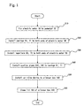
- the outline of the manufacturing process of the ventilating device will be described with reference to FIG. 1.
- An electric motor 55 is fixed to a pedestal 50 (step S10).
- An exhaust casing 61 and an air supply casing 71 of a blower are mounted to both sides of the electric motor 55 fixed to the pedestal 50 (step S20).
- Impellers 63, 73 are respectively mounted to both shaft ends of the electric motor 55 (step S30).
- a suction pipe for exhaust 64c and a suction pipe for air supply 74c are respectively mounted to the exhaust casing 61 and the air supply casing 71 (step S40).
- the unit manufactured in the process of the above-mentioned step S10 through step S40 is called an air blow device.
- the above-mentioned air blow device is mounted to the interior of a silencer box 100 with built-in air supply flow path and exhaust flow path.
- the air blow device is electrically wired. Also, the opening through which the air blow device was inserted is closed by a lid 150. After carrying out other final operations, the process is completed (step S50).
- Step S10 The electric motor 55 of the both shaft type is attached onto the pedestal 50 by screws, in FIG. 2 and FIG. 3.
- the shaft of the electric motor 55 is provided in the horizontal direction.
- the pedestal 50 is constituted by combining a flat plate and channel materials. When seen from above, the end portions of the pedestal 50 project further than the electric motor 55. With such configuration, the pedestal 50 could be inserted into the silencer box 100 and then attached thereto with screws from above.
- the pedestal 50 includes screw holes or nuts, and the electric motor includes holes for passing the screws through.
- the attaching portions of the screws mentioned later have screw holes on one of the members, and holes on the other.
- Step S20 The casing 61 for blower for exhaust, and the air supply casing 71 are respectively installed to both ends of the electric motor 55, in FIG. 4 and FIG. 5.
- the blower is a multiblade fan.
- brackets 65, 66, 75, 76 are attached to the upper surface of the pedestal 50 by screws from above.
- the casings 61, 71 are attached to end brackets of the electric motor 55 with screws via cushionings 68, 78.
- the plates of casings 61, 71 on the side of the electric motor 55 are attached. This attachment is performed through an opening 61b (opening 71b is not shown) for inserting impeller of the casings 61, 71.
- Air outlets 62, 72 of the casings 61, 71 are equipped with flanges 62b, 72b projecting abroad. The flange 72b is especially necessary.
- the upper brackets 66, 76 of the casings 61, 71 are connected together from above by a rigid connecting member 67.
- the connection is performed by attaching with screws from above.
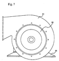
- Step S30 The impellers 63, 73 are mounted to both shaft ends of the electric motor 55, in FIG. 6 and FIG. 7.
- the mounting is performed from the opening 61b on the suction hole side of the casings 61, 71.
- the opening 61b is larger than the outer diameter of the impellers 71, 72.
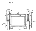
- Step S40 Members 64, 74 for the suction holes are mounted to the plates on the suction hole side of the casings 61, 71, in FIG. 8 and FIG. 9.
- member 64 of the suction hole it is comprised of a flange 64b for covering the opening 61b, and a suction pipe 64c.
- Flange 64b is attached to the casing 61 with screws.
- the suction pipe 64c is expanded at the suction side.
- member 74 is comprised of a flange 64b for covering the opening 61b, and a suction pipe 64c.
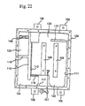
- Step S50 It will be explained with reference to FIG. 10 through FIG. 24.
- the unit obtained in step S40 will be called the air blow device.
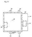
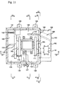
- This air blow device is inserted through the opening at the upper surface of the silencer box 100, and is fixed thereto. Also, the electric motor 55 is performed with wiring operation, and the opening is covered by the lid 150. Also, the connection of the exhaust duct unit 180 is conducted.
- the ventilating device is comprised of the silencer box 100 with the air blow device stored therein, and the exhaust duct unit 180.
- An outlet 136 for air supply flow path is provided at the upper surface of the silencer box 100.
- An inlet 131 for air supply flow path is provided at the rear surface of the silencer box 100.
- the exhaust duct unit 180 is fixed to the right side surface of the silencer box 100.
- An inlet 191 for exhaust flow path is provided at upper surface of the exhaust duct unit 150.
- the openings 136, 191 are connected to a passenger car of the car body through the ducts. Screw holes for connecting with the duct at the car body side are provided to peripheries of the openings 136, 191.
- An outlet 196 for exhaust flow path is provided at the right side surface of the exhaust duct unit 180.
- Reference number 106 denotes a pedestal for suspending from the car body.
- the silencer box 100 is comprised of a silencer box and a lid 150.
- the lid 150 closes the upper surface of the silencer box 100.
- the lid 150 is attached to the upper portion of the silencer box 100 with screws.
- the silencer box 100 is a square box made of metal.
- the silencer box includes a bottom, but is opened at the upper surface thereof.
- the exhaust flow path and the air supply flow path are constituted by partitioning the box with partitions.
- the silencer box 100 is provided with inlets 121, 131 and outlets 126, 136 for respective air flow paths.
- the inlet 121 and the outlet 126 of the exhaust flow path are opened at the plate of the right side surface of the silencer box 100.
- the inlet 131 of the air supply flow path is opened at the rear surface, and the outlet 136 is opened at the upper surface, that is, at the lid 150.
- the upper surface of the lid 150 is a plate made of metal.
- the left side of the silencer box 100 is the air supply flow path, and the right side thereof is the exhaust flow path.
- the exhaust flow path is comprised of a flow path 122 running from the front surface side of the silencer box 100 to the rear surface side, and a flow path 123 running along the rear surface.
- the air from the blower for exhaust is ejected to the front surface side.
- the flow path 122 and the flow path 123 are partitioned by a partition 115.
- the opening from the flow path 122 to the flow path 123 is provided to the lower portion of the silencer box 110.
- the flow path 123 is connected to the outlet 126.
- the exhaust flow path and the air supply flow path are parted to left and right by the partition 110.
- the partition 110 extends from the vicinity of the front surface side to the plate of the rear surface.
- the partition 110 is provided with an opening 133 for the entrance to the blower for air supply.
- Partitions 116, 117 are provided between the front surface side of the partition 110 and the plate of the front surface.
- the plate 116 is provided with an opening opposing the outlet 72 of the blower for air supply.
- the partition 117 partitions the inner portion of the front surface side to left and right.
- the air supply flow path is partitioned to a flow path 132 of the inlet side and a flow path 134 of the outlet side with a partition 119.
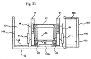
- the wall surfaces constituting the exhaust flow path and the air supply flow path that is, the inner surface of the plates of the silencer box 100, the partitions 110, 115, 116, 117, 119 and the like, and the inner surface of the plates of the lid 150, are affixed with sound absorbing materials 108 to constitute the silencer.
- the corner portions of the air flow paths are formed in arcuate shape.
- the outer surface of the sound absorbing material is suitably covered with punching metals.
- the silencer box 100 is provided with a bottom, and a pedestal 105 for resting the pedestal 50 is provided to the upper surface of the bottom plate.
- the lower portion of the electric motor 55 is installed with the sound absorbing material 108c.
- the casings 61, 71 are positioned to both sides of the pedestal 105.
- the lid 150 is rested on a depressed flange at the upper surface of the silencer box 100, and is attached thereto from above with screws.
- the air blow device obtained in S40 is inserted into the silencer box 100 without the lid 150, and is rested on the pedestal 105.
- the end portions of a base 50 are attached to the pedestal 105 from above with screws.
- the air blow device has its rotary shaft positioned in left and right directions.
- the outlets 62, 72 of the respective blowers are facing the front surface side. It is preferable to rest the air blow device through a vibration-proof rubber.
- a wire 107 is connected to a terminal base of the electric motor 55.
- the wire 107 is pierced through the silencer box 100 in advance.
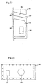
- the partition 111 is installed at the inner surface of the plate at the right side surface of the silencer box (blower side).
- the partition 112 is installed at the partition 110. The partition 112 is positioned more toward the blower side than the partition 110.
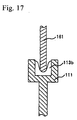
- the cross-section of the semicircular recessed portion includes a U-shaped groove.
- the groove is arranged with cross-sectionally U-shaped cushioning 113.
- the leading end of the suction pipe 64c comes into contact with the cushioning 113.
- the partition 111 above the semicircular recessed portion is expanded in a trapezoid shape.
- a cross-sectionally U-shaped cushioning 113b is arranged to the trapezoid portion. The same applies to the partition 112.
- the lid 150 is attached to the silencer box 100 from above with screws.
- the lower surface of the lid 150 is arranged with the sound absorbing materials opposing the flow paths 122, 123, 132, 134 and the like.
- the cusionings are arranged in order to prevent air leakage.
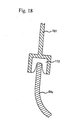
- Partitions 161, 162 for closing the openings of the partitions 111, 112 are suspended from the lower surface of the lid 150.
- the lower end of the partition 161 is formed in a semicircular recessed portion coming into contact with the semicircular portion of the upper portion of the suction pipe 64c.
- the recessed portion is provided with a U-shaped groove.
- the groove is arranged with a U-shaped cushioning 113.
- the leading end of the suction pipe 64c comes into contact with the cushioning 113.
- both sides of the recessed semicircular portion 121b are expanded in trapezoid shape in conformity with the partition 111.
- the trapezoid portion comes into contact with the cushioning 113b.
- the position in the silencer box 100 where the air blow device is inserted is in the exhaust flow path 122.
- the electric motor 55, the blower for exhaust, and the blower for air supply are all positioned in the exhaust flow path 120.
- the outlet 62 of the blower for exhaust is positioned in the exhaust flow path 122.
- the flange 72b of the opening 72 of the blower for air supply comes into contact with the partition 116 partitioning the exhaust flow path 120 and the air supply flow path 130.
- the cushioning is arranged between the two. To make sure that the flange 72b comes into contact with the partition 116, the air blow device is forced against the front surface side of the silencer box 100, and the base 50 is attached to the pedestal 105.
- the exhaust duct unit 180 is fixed to the plate at the right side surface of the silencer box 100 with screws.
- the exhaust duct unit 180 is a square box, with six sides thereof covered with plates. A flange for mounting is provided to the outer periphery at the left end.
- the exhaust duct unit 180 includes a suction flow path 192 and an exhaust flow path 196.
- An inlet 191 of the suction flow path 192 is opened at the upper surface.
- An outlet 197 of the exhaust flow path 196 is opened at the right side surface.
- An outlet 193 of the suction flow path 192 and the inlet 195 of the exhaust flow path 196 are opened at the left side surface. The outlet 193 opposes the suction pipe 64c of the exhaust blower.
- the outlet 193 comes into contact with partitions 111, 161 via cushionings.
- the inlet 195 of the exhaust flow path 196 opposes the outlet 123 of the exhaust flow path.
- the inlet 195 comes into contact with the plate of the right side surface of the silencer box via the cushioning. Therefore, the outlet 193 projects more towards the silencer box 100 side than the inlet 195.
- the sound absorbing material is installed to the wall surfaces of the air flow paths 192, 196 of the exhaust duct unit 180.
- the sound absorbing materials are installed to the plates for six surfaces of the exhaust duct unit 180, and to the partition for partitioning the flow path 192 and the flow path 196. After arranging the sound absorbing material to the interior, the plate for one of the surfaces is fixed to constitute the exhaust duct unit 180.
- the exhaust air from the inlet 191 reaches the blower for exhaust through the flow path 192 and the suction pipe 64c.
- the exhaust air is boosted at this point, and is discharged to the front surface side of the flow path 122.
- the electric motor 55 is placed in the flow path 122, so that the exhaust air cools the electric motor 55. Then, it is ejected to the exterior via the flow paths 123, 196.
- the fresh air entering from the inlet 131 reaches the blower for air supply from the suction pipe 74c via a flow path resistor 140 and the flow path 132.
- the fresh air is boosted at this point, and is discharged to the front surface side of the flow path 134, and reaches the outlet 136 via the flow path 134.
- the flow path resistor 140 changes the opening rate of the air flow path. By changing the opening rate, the amount of air entering the car is determined, and the pressure inside the car is set at a predetermined amount. The setting of the opening rate is performed from the inlet 131.
- the assembly of the air blow device could all be performed from above or from the side. Also, it could be assembled by inserting the air blow device to the silencer box 100 from above. Therefore, the assembly could be performed with ease.
- the above-mentioned box is arranged with sound absorbing material to constitute a silencer, therefore noise could be reduced.
- disassembling for the purpose of maintenance operation could be performed by removing the ventilating device from the car body, and then removing the lid 150 and pulling out the air blow device upwardly.
- the members 64, 74 of the suction holes are removed, and the cleaning of the impellers 63, 73 are carried out.
- This cleaning could be performed by removing the impellers 63, 73 from the shaft.
- the exchange of the bearings could be per formed by removing the casings 61, 71 from the end brackets of the electric motor 55, and then removing the end brackets.
- the silencer box 100 contains two blowers for air supply and exhaust, therefore four openings must be present. However, this opening could serve both as the opening for inserting the air blow device.
- the outlet 136 of the air supply flow path serves both as the opening for inserting the air blow device, and is provided at the lid 150.
- the outlet 126 of the exhaust flow path could be installed at the lid 150.
- the silencer box 100 should have four openings for air supply and exhaust as a result, and there is no need to have four openings in the box before being covered by the lid 150.
- the blower rotates at high speed. Therefore, there is a fear that the casings of the blower might vibrate.
- rigidity By fixing the lower portions of the casings 61, 71 to the pedestal 50, and fixing the upper portions of the casings 61, 71 together with plurality of connecting members 67, rigidity could be improved, and vibration could be restrained.
- the partitions 161, 162 are installed on the second lid. By doing so, it becomes easier to align the partitions 161, 162 with partitions 111, 112.
- the relation between the outlet 72 of the blower for air supply and the partition 116 may be made the same as the relation between the suction pipe 64c (74c) and the partitions 111, 161 (112, 162).
- the flange 72b of the outlet 72 may be formed slightly downwardly, and the partition 116 may be formed slightly upwardly, and the two may be connected via the cushioning.
- the partitions 112, 162 may not be necessary.
- the inlet 133 is opened on the partition 110.
- the flange of the suction hole of the suction tube 74c comes into contact with the partition 110 via the cushioning. This contact is performed by pushing the electric motor 55 towards the partition 110 side. Further, in the case with the structure where the flange 72b of the outlet 72 of the blower for exhaust contacts the partition 116, the electric motor 55 is pushed towards the left side and the front surface side.
- the partitions 111, 161 may not be necessary.
- the inlet 121 is opened at the plate of the right side surface of the silencer box 100.
- the member of the outlet 193 of the exhaust duct unit 180 comes into contact with the flange of the suction pipe 64c via the cushioning. This contact is performed by fixing the exhaust duct unit 180 to the silencer box 100. When the outlet 193 is projected, the thickness of the cushioning may be thinned.
- the unit including the flow paths 132, 134 may be made in a different unit from the silencer box 100.
- the electric motor 55 is provided inside the air flow path to keep cool. Therefore, it is preferable to form the connecting member 67b in an arcuate shape along the housing of the electric motor 55, so that the air flows along the electric motor 55.
- the sound absorbing material 108b (shown in FIG. 19) of the lid 150 is arranged adjacent to the upper surface of the front surface side of the connecting member 67b. With such arrangement, the amount of air flowing along the upper surface of the connecting member 67b could be made smaller, and the amount of air towards the electric motor 55 side could be made larger, enabling effective cooling.
- the width of the sound absorbing material 108b is about the length between the casings 61 and 71.
- Air could be discharged directly from the silencer box 100 directly to the atmosphere, excluding the flow path 196 of the exhaust duct unit 180. Also, as the air supply flow path is provided inside the silencer box 100, the flow paths 192, 196 of the exhaust duct unit may be provided inside the silencer box 100.
- Equipment for controlling the electric motor 55 such as an inverter and the like, may be installed to the air flow path to cool. For example, it is installed to the lid 150.
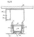
- FIG. 26 This is a longitudinal cross-sectional view of the condition where the air blow device is pulled out downwardly.
- This example is the case where the opening for inserting the air blow device is provided to the lower surface of the silencer box 200.
- the other structures are the same as the above-mentioned example, except that the exhaust duct unit 180 connected to the right side surface is not shown. In the case of a maintenance operation, the exhaust duct unit 180 is removed, and then the air blow device is pulled out downwardly.
- the silencer box 200 remains mounted to the car body 250.
- the pedestal 50 of the air blow device is installed to the plate (lid) 210 for covering the opening at the lower surface of the silencer box 200.
- the plate 210 is constituted firmly.
- the plate 210 is fixed to the silencer box 200.
- the air blow device is moved vertically in the above-mentioned example, but it may be stored by moving the same horizontally.
- the connection between the suction hole and the outlet of the blower could be made simple. In this case, it is preferable to face the outlet of the blower slightly towards the direction of movement. Also, it is preferable to construct so that the electric motor moves along a rail.
- the above-mentioned example is a combination of two blowers in one electric motor and one silencer box. However, it may be formed in a combination of one blower and one silencer box. In this case, there should be two openings for ventilation to one silencer box as a result.
- the blower In the case of inserting from the horizontal direction, the blower should be inserted by providing the outlet of the blower to face the direction of insertion (rear surface side), so that the outlet of the blower comes into contact with the partition.
- the assembly operation and the disassembly operation could be performed with ease.
Landscapes
- Engineering & Computer Science (AREA)
- Mechanical Engineering (AREA)
- General Engineering & Computer Science (AREA)
- Structures Of Non-Positive Displacement Pumps (AREA)
- Ventilation (AREA)
Abstract
Description
Claims (25)
- A method of manufacturing a ventilating device, the method comprising:inserting a ventilating blower including an electric motor to an air flow path of a box with the ability to include at least two openings as a result for ventilation, in a vertical direction or in a horizontal direction; andfixing said ventilating blower to said box with a rotary shaft thereof arranged in a horizontal direction, as well as covering said opening for insertion with a plate.
- A method of manufacturing a ventilating device according to claim 1, comprising:inserting said ventilating blower from above said box, and fixing the same from above; andcovering said opening at upper surface of said box through which said ventilating blower is inserted with said plate.
- A method of manufacturing a ventilating device according to claim 1, comprising:
inserting said ventilating blower from a lower surface of said box, in a condition where said ventilating blower is rested on top of said plate. - A method of manufacturing a ventilating device according to claim 1, comprising:
inserting said ventilating blower from the horizontal direction of the shaft direction of the rotary shaft. - A method of manufacturing a ventilating device according to claim 1, comprising:
providing said box at wall surfaces of said air flow paths in advance with sound absorbing materials. - A method of manufacturing a ventilating device according to claim 1, comprising:installing said ventilating blower with a blower for exhaust and a blower for air supply at each ends of one electric motor; andperforming said insertion to place said electric motor in one of said air flow paths.
- A method of manufacturing a ventilating device according to claim 1, comprising:
mounting a duct to a side surface of said box after mounting said ventilating blower to said box, and at this point, contacting an air flow path of said duct to a suction hole of a suction pipe of said ventilating blower. - A method of manufacturing a ventilating device according to claim 7, with said duct being equipped with two air flow paths, the step comprising:
contacting one of said air flow path with a suction hole of a suction pipe of said ventilating blower, and contacting the other of said air flow path with an air flow path from said blower, when mounting said duct to said box. - A method of manufacturing a ventilating device according to claim 1, with said ventilating blower including a blower for exhaust and a blower for air supply to each ends of one electric motor, the step comprising:fixing said ventilating blower by contacting a suction hole of one of said blowers with a partition inside said box; andsubsequently mounting a duct to a side surface of said box, and at this time, contacting an air flow path of said duct with a suction hole of a suction pipe of said ventilating blower.
- A method of manufacturing a ventilating device according to claim 1, comprising:inserting said ventilating blower with an outlet facing the direction of insertion;mounting said ventilating blower to said box; andmounting a duct to a side surface of said box, and at this time, contacting an air flow path of said duct to a suction hole of a suction pipe of said ventilating blower.
- A ventilating device, comprising:a ventilating blower installed inside an air flow path inside a box, including an electric motor with an rotary shaft provided in a horizontal direction;an opening provided to a surface in a vertical direction or in a horizontal direction of said box, for inserting said ventilating blower;a plate for covering said opening; andat least two openings for ventilation provided to a structure comprising said box and said lid.
- A ventilating device according to claim 11, wherein said opening for inserting said ventilating blower is provided to an upper surface of said box; and
said plate is placed on an upper surface of said box. - A ventilating device according to claim 11, wherein said opening for inserting said ventilating blower is provided to a lower surface of said box; and
said plate is positioned at a lower surface of said box, and is resting said electric motor on top thereof. - A ventilating device according to claim 11, wherein said opening and said plate is provided to a surface in the shaft direction of said rotary shaft of said ventilating blower.
- A ventilating device according to claim 11, wherein sound absorbing materials are arranged to wall surfaces constituting said air flow paths inside said box.
- A ventilating device according to claim 11, wherein a duct is mounted to a side surface of said box; and
an air flow path of said duct comes into contact with a suction hole of said ventilating blower. - A ventilating device according to claim 16, wherein said duct is two in number;one of said duct is mounted to one side surface of said box; andthe other said duct is mounted to another side surface opposing said one side surface.
- A ventilating device according to claim 11, wherein a duct including two air flow paths is mounted to a side surface of said box;a downstream end of one said air flow path comes into contact with said suction hole of said ventilating blower; andanother said air flow path comes into contact with another said opening on a side surface of said box.
- A ventilating device according to claim 11, wherein casings of said ventilating blower are fixed to end brackets of said electric motor; and
members of air suction holes of said ventilating blower are larger in diameter than impellers of said ventilating blower, and are provided detachably to said casings. - A ventilating device according to claim 11, wherein said ventilating blower includes a blower for exhaust and a blower for air supply to each end of one electric motor; and
said electric motor is installed in one of said air flow paths. - A ventilating device according to claim 11, wherein said ventilating blower includes a blower for exhaust and a blower for air supply to each end of one electric motor;a suction hole of one blower is in contact with a partition inside said box; anda suction hole of the other blower is in contact with an air flow path of a duct installed to a side surface of said box.
- A ventilating device according to claim 11, wherein eachsaid blowers includes suction pipes projecting in horizontal directions;said box below at least one said suction pipe includes a semicircular partition contacting the lower surface of said suction pipe; andsaid plate includes a semicircular partition contacting the upper surface of said suction pipe, opposing said semicircular partition.
- A ventilating device according to claim 11, wherein said ventilating blower includes a blower for exhaust and a blower for air supply to each end of one electric motor;casings of said respective blowers are fixed to end brackets of said electric motor; andone said casing and the other said casing are connected with a rigid body.
- A ventilating device according to claim 23, wherein lower portions of said each casings are fixed to a pedestal for resting said electric motor.
- A ventilating device according to claim 23, wherein said rigid body is provided continuously along said electric motor.
Applications Claiming Priority (3)
| Application Number | Priority Date | Filing Date | Title |
|---|---|---|---|
| JP493799 | 1999-01-12 | ||
| JP00493799A JP3254428B2 (en) | 1999-01-12 | 1999-01-12 | Ventilation apparatus manufacturing method and ventilation apparatus |
| PCT/JP2000/000099 WO2000042325A1 (en) | 1999-01-12 | 2000-01-12 | Method of manufacturing ventilating device and the ventilating device |
Publications (3)
| Publication Number | Publication Date |
|---|---|
| EP1143150A1 true EP1143150A1 (en) | 2001-10-10 |
| EP1143150A4 EP1143150A4 (en) | 2003-07-02 |
| EP1143150B1 EP1143150B1 (en) | 2005-06-01 |
Family
ID=11597499
Family Applications (1)
| Application Number | Title | Priority Date | Filing Date |
|---|---|---|---|
| EP00900340A Expired - Lifetime EP1143150B1 (en) | 1999-01-12 | 2000-01-12 | Method of manufacturing ventilating device and the ventilating device |
Country Status (9)
| Country | Link |
|---|---|
| US (1) | US6638036B1 (en) |
| EP (1) | EP1143150B1 (en) |
| JP (1) | JP3254428B2 (en) |
| KR (1) | KR100453274B1 (en) |
| CN (2) | CN100441971C (en) |
| DE (1) | DE60020525T2 (en) |
| ES (1) | ES2239585T3 (en) |
| TW (1) | TWI246976B (en) |
| WO (1) | WO2000042325A1 (en) |
Cited By (1)
| Publication number | Priority date | Publication date | Assignee | Title |
|---|---|---|---|---|
| EP1512601A1 (en) | 2003-09-03 | 2005-03-09 | Hitachi, Ltd. | Method of operating ventilator and air conditioner for vehicle |
Families Citing this family (8)
| Publication number | Priority date | Publication date | Assignee | Title |
|---|---|---|---|---|
| US7992249B2 (en) | 2006-10-30 | 2011-08-09 | Federal-Mogul World Wide, Inc. | Wiper arm assembly having locking arms |
| CN102211046A (en) * | 2010-04-09 | 2011-10-12 | 鸿富锦精密工业(深圳)有限公司 | Constant temperature cabinet |
| CN103017288B (en) * | 2012-12-31 | 2015-06-10 | 深圳市中兴新地通信器材有限公司 | Intelligent fresh air system |
| CN104132003B (en) * | 2014-07-30 | 2016-08-17 | 邵阳万脉科技有限公司 | A kind of silencing means of positive airway pressure equipment |
| US10375901B2 (en) | 2014-12-09 | 2019-08-13 | Mtd Products Inc | Blower/vacuum |
| KR102171602B1 (en) | 2019-01-10 | 2020-10-29 | 효성중공업 주식회사 | Rotor of motor |
| DE102022130919A1 (en) * | 2022-11-22 | 2024-05-23 | Zitt Motoren Ag | Drive unit for a fan with a speed coding based on a selective energy transfer via two separate electrical connection cable systems |
| CN117489395B (en) * | 2023-12-29 | 2024-04-05 | 中铁六局集团太原铁路建设有限公司 | Ventilation device for arched tunnel and use method thereof |
Family Cites Families (30)
| Publication number | Priority date | Publication date | Assignee | Title |
|---|---|---|---|---|
| US2710573A (en) | 1951-04-30 | 1955-06-14 | Trade Wind Motorfans Inc | Air handling apparatus |
| JPS4741040Y1 (en) * | 1970-10-07 | 1972-12-12 | ||
| US3688867A (en) | 1971-06-30 | 1972-09-05 | Ibm | Acoustically improved blower package |
| JPS5410722B2 (en) * | 1973-03-02 | 1979-05-09 | ||
| JPS5548158Y2 (en) * | 1974-07-11 | 1980-11-11 | ||
| JPS5827332Y2 (en) * | 1979-01-18 | 1983-06-14 | 三菱電機株式会社 | ventilation fan |
| JPS57154195U (en) * | 1981-03-23 | 1982-09-28 | ||
| JPS59195195U (en) * | 1983-06-15 | 1984-12-25 | 三菱重工業株式会社 | Disassembly jig for overhang type pump |
| JPS60113097A (en) * | 1983-11-25 | 1985-06-19 | Matsushita Electric Ind Co Ltd | electric blower |
| JPH0136039Y2 (en) * | 1984-09-27 | 1989-11-02 | ||
| JPH0112970Y2 (en) * | 1985-08-29 | 1989-04-17 | ||
| JPS6436039A (en) * | 1987-07-31 | 1989-02-07 | Nec Corp | Semiconductor device |
| JPH0341117Y2 (en) * | 1987-11-19 | 1991-08-29 | ||
| JP2685521B2 (en) * | 1988-08-05 | 1997-12-03 | 株式会社日立製作所 | Vehicle ventilation system |
| JPH0396420A (en) * | 1989-09-08 | 1991-04-22 | Matsushita Electric Ind Co Ltd | Motor supporting structure of vehicle air conditioner |
| JP2507084B2 (en) * | 1989-09-11 | 1996-06-12 | 松下電器産業株式会社 | Motor support structure for vehicle air conditioners |
| DE69122795T2 (en) * | 1990-03-19 | 1997-05-07 | Hitachi Ltd | Ventilation equipment for railway passenger cars and their application |
| JPH0471404A (en) * | 1990-07-10 | 1992-03-06 | Toshiba Corp | Apparatus for cutting plant body |
| US5403163A (en) * | 1990-08-20 | 1995-04-04 | Molded Products Company | Motor mount for blower housing |
| JPH08534B2 (en) | 1990-09-19 | 1996-01-10 | 株式会社日立製作所 | Ventilation system for vehicles |
| US5804263A (en) * | 1990-10-24 | 1998-09-08 | University Of Florida Research Foundation, Inc. | Combined plasma and gamma radiation polymerization method for modifying surfaces |
| TW205538B (en) * | 1991-02-08 | 1993-05-11 | Hitachi Seisakusyo Kk | |
| JPH0577726A (en) | 1991-09-19 | 1993-03-30 | Hitachi Ltd | Vehicle ventilation device and control method thereof |
| JP2734848B2 (en) | 1991-12-27 | 1998-04-02 | 株式会社日立製作所 | Vehicle ventilation system |
| JP2894104B2 (en) * | 1992-09-09 | 1999-05-24 | 株式会社日立製作所 | VEHICLE VENTILATION DEVICE AND CONTROL METHOD THEREOF |
| EP0734768B1 (en) | 1995-04-01 | 2002-08-28 | Roche Diagnostics GmbH | Method of binding a biological substance |
| CN2292179Y (en) * | 1995-05-23 | 1998-09-23 | 顺德市正野电器实业公司 | Scavenge fan |
| DE29520020U1 (en) * | 1995-12-18 | 1996-02-01 | Dürr GmbH, 70435 Stuttgart | Large fan for process technology, ventilation of workshops and the like. |
| JPH10281097A (en) * | 1997-04-10 | 1998-10-20 | Hitachi Ltd | Vehicle ventilation system |
| JP5410722B2 (en) * | 2008-09-30 | 2014-02-05 | 三菱化学メディエンス株式会社 | Method for detecting pancreatic tissue injury or cell proliferative disease |
-
1999
- 1999-01-12 JP JP00493799A patent/JP3254428B2/en not_active Expired - Fee Related
-
2000
- 2000-01-12 WO PCT/JP2000/000099 patent/WO2000042325A1/en not_active Ceased
- 2000-01-12 CN CNB2003101043951A patent/CN100441971C/en not_active Expired - Lifetime
- 2000-01-12 EP EP00900340A patent/EP1143150B1/en not_active Expired - Lifetime
- 2000-01-12 KR KR10-2001-7008713A patent/KR100453274B1/en not_active Expired - Fee Related
- 2000-01-12 CN CNB008026653A patent/CN100379999C/en not_active Expired - Lifetime
- 2000-01-12 TW TW089100383A patent/TWI246976B/en not_active IP Right Cessation
- 2000-01-12 DE DE60020525T patent/DE60020525T2/en not_active Expired - Lifetime
- 2000-01-12 US US09/869,046 patent/US6638036B1/en not_active Expired - Fee Related
- 2000-01-12 ES ES00900340T patent/ES2239585T3/en not_active Expired - Lifetime
Cited By (1)
| Publication number | Priority date | Publication date | Assignee | Title |
|---|---|---|---|---|
| EP1512601A1 (en) | 2003-09-03 | 2005-03-09 | Hitachi, Ltd. | Method of operating ventilator and air conditioner for vehicle |
Also Published As
| Publication number | Publication date |
|---|---|
| KR20010101450A (en) | 2001-11-14 |
| US6638036B1 (en) | 2003-10-28 |
| EP1143150A4 (en) | 2003-07-02 |
| TWI246976B (en) | 2006-01-11 |
| CN100441971C (en) | 2008-12-10 |
| JP3254428B2 (en) | 2002-02-04 |
| CN1336989A (en) | 2002-02-20 |
| CN100379999C (en) | 2008-04-09 |
| DE60020525D1 (en) | 2005-07-07 |
| ES2239585T3 (en) | 2005-10-01 |
| WO2000042325A1 (en) | 2000-07-20 |
| JP2000205198A (en) | 2000-07-25 |
| EP1143150B1 (en) | 2005-06-01 |
| CN1570502A (en) | 2005-01-26 |
| KR100453274B1 (en) | 2004-10-15 |
| DE60020525T2 (en) | 2006-05-11 |
Similar Documents
| Publication | Publication Date | Title |
|---|---|---|
| US6638036B1 (en) | Method of manufacturing ventilating device and the ventilating device | |
| US4062273A (en) | Ventilation system for a passenger vehicle | |
| CN117940712A (en) | Outdoor unit of air conditioner | |
| KR102047268B1 (en) | Portable compressed air feeder | |
| JP3563050B2 (en) | How to make a ventilation system | |
| US2112277A (en) | Air conditioning unit | |
| JP3947078B2 (en) | Method of manufacturing blower and blower | |
| JP2002272061A (en) | Main motor for vehicle | |
| JP2006242545A (en) | Indoor unit and air conditioner | |
| JP6184574B2 (en) | Air conditioner for vehicles | |
| JP2002079937A (en) | Method of manufacturing ventilator and ventilator | |
| JP2010117103A (en) | Air conditioning indoor unit | |
| JPWO2016194750A1 (en) | Air compressor | |
| JP2549782Y2 (en) | Air-cooled package lubricated screw compressor | |
| CN218269444U (en) | Air purification and ventilation system for rail transit platform and station hall | |
| CN113498393A (en) | Air interchanger for rail vehicle | |
| JPH082244A (en) | Air conditioner for vehicle | |
| JP3611264B2 (en) | Air conditioner | |
| CN117017111A (en) | Vacuum cleaner fans, vacuum cleaner base stations and cleaning equipment | |
| KR200360679Y1 (en) | Cool air division supplying apparatus for trection motor of rail cars | |
| JP2010096135A (en) | Blower with sound attenuation box | |
| JP2006273157A (en) | Continuous ventilation system for vehicles | |
| JP2000274746A (en) | Method for taking out engine from outdoor machine of air-conditioning | |
| JPS63198555A (en) | Squirrel cage induction motor | |
| JPH10122724A (en) | Cooling structure of condenser in cooled storage |
Legal Events
| Date | Code | Title | Description |
|---|---|---|---|
| PUAI | Public reference made under article 153(3) epc to a published international application that has entered the european phase |
Free format text: ORIGINAL CODE: 0009012 |
|
| AK | Designated contracting states |
Kind code of ref document: A1 Designated state(s): AT BE CH CY DE DK ES FI FR GB GR IE IT LI LU MC NL PT SE |
|
| 17P | Request for examination filed |
Effective date: 20010711 |
|
| RIC1 | Information provided on ipc code assigned before grant |
Ipc: 7F 04D 25/16 B Ipc: 7F 04D 29/62 A Ipc: 7F 04D 29/60 B |
|
| A4 | Supplementary search report drawn up and despatched |
Effective date: 20030519 |
|
| 17Q | First examination report despatched |
Effective date: 20040415 |
|
| RBV | Designated contracting states (corrected) |
Designated state(s): DE ES FR IT |
|
| GRAP | Despatch of communication of intention to grant a patent |
Free format text: ORIGINAL CODE: EPIDOSNIGR1 |
|
| GRAS | Grant fee paid |
Free format text: ORIGINAL CODE: EPIDOSNIGR3 |
|
| GRAA | (expected) grant |
Free format text: ORIGINAL CODE: 0009210 |
|
| AK | Designated contracting states |
Kind code of ref document: B1 Designated state(s): DE ES FR IT |
|
| REG | Reference to a national code |
Ref country code: IE Ref legal event code: FG4D |
|
| REF | Corresponds to: |
Ref document number: 60020525 Country of ref document: DE Date of ref document: 20050707 Kind code of ref document: P |
|
| REG | Reference to a national code |
Ref country code: ES Ref legal event code: FG2A Ref document number: 2239585 Country of ref document: ES Kind code of ref document: T3 |
|
| ET | Fr: translation filed | ||
| PLBE | No opposition filed within time limit |
Free format text: ORIGINAL CODE: 0009261 |
|
| STAA | Information on the status of an ep patent application or granted ep patent |
Free format text: STATUS: NO OPPOSITION FILED WITHIN TIME LIMIT |
|
| 26N | No opposition filed |
Effective date: 20060302 |
|
| PGFP | Annual fee paid to national office [announced via postgrant information from national office to epo] |
Ref country code: ES Payment date: 20141211 Year of fee payment: 16 |
|
| REG | Reference to a national code |
Ref country code: FR Ref legal event code: PLFP Year of fee payment: 17 |
|
| REG | Reference to a national code |
Ref country code: FR Ref legal event code: PLFP Year of fee payment: 18 |
|
| REG | Reference to a national code |
Ref country code: ES Ref legal event code: FD2A Effective date: 20170228 |
|
| PG25 | Lapsed in a contracting state [announced via postgrant information from national office to epo] |
Ref country code: ES Free format text: LAPSE BECAUSE OF NON-PAYMENT OF DUE FEES Effective date: 20160113 |
|
| REG | Reference to a national code |
Ref country code: FR Ref legal event code: PLFP Year of fee payment: 19 |
|
| PGFP | Annual fee paid to national office [announced via postgrant information from national office to epo] |
Ref country code: FR Payment date: 20181213 Year of fee payment: 20 |
|
| PGFP | Annual fee paid to national office [announced via postgrant information from national office to epo] |
Ref country code: IT Payment date: 20190121 Year of fee payment: 20 Ref country code: DE Payment date: 20190102 Year of fee payment: 20 |
|
| REG | Reference to a national code |
Ref country code: DE Ref legal event code: R071 Ref document number: 60020525 Country of ref document: DE |