EP1142935A2 - Plastic parts joining structure - Google Patents
Plastic parts joining structure Download PDFInfo
- Publication number
- EP1142935A2 EP1142935A2 EP01108729A EP01108729A EP1142935A2 EP 1142935 A2 EP1142935 A2 EP 1142935A2 EP 01108729 A EP01108729 A EP 01108729A EP 01108729 A EP01108729 A EP 01108729A EP 1142935 A2 EP1142935 A2 EP 1142935A2
- Authority
- EP
- European Patent Office
- Prior art keywords
- plastic part
- plastic
- joining
- joining structure
- structure according
- Prior art date
- Legal status (The legal status is an assumption and is not a legal conclusion. Google has not performed a legal analysis and makes no representation as to the accuracy of the status listed.)
- Withdrawn
Links
Images


Classifications
-
- C—CHEMISTRY; METALLURGY
- C09—DYES; PAINTS; POLISHES; NATURAL RESINS; ADHESIVES; COMPOSITIONS NOT OTHERWISE PROVIDED FOR; APPLICATIONS OF MATERIALS NOT OTHERWISE PROVIDED FOR
- C09J—ADHESIVES; NON-MECHANICAL ASPECTS OF ADHESIVE PROCESSES IN GENERAL; ADHESIVE PROCESSES NOT PROVIDED FOR ELSEWHERE; USE OF MATERIALS AS ADHESIVES
- C09J123/00—Adhesives based on homopolymers or copolymers of unsaturated aliphatic hydrocarbons having only one carbon-to-carbon double bond; Adhesives based on derivatives of such polymers
- C09J123/02—Adhesives based on homopolymers or copolymers of unsaturated aliphatic hydrocarbons having only one carbon-to-carbon double bond; Adhesives based on derivatives of such polymers not modified by chemical after-treatment
- C09J123/04—Homopolymers or copolymers of ethene
- C09J123/06—Polyethene
-
- B—PERFORMING OPERATIONS; TRANSPORTING
- B29—WORKING OF PLASTICS; WORKING OF SUBSTANCES IN A PLASTIC STATE IN GENERAL
- B29C—SHAPING OR JOINING OF PLASTICS; SHAPING OF MATERIAL IN A PLASTIC STATE, NOT OTHERWISE PROVIDED FOR; AFTER-TREATMENT OF THE SHAPED PRODUCTS, e.g. REPAIRING
- B29C65/00—Joining or sealing of preformed parts, e.g. welding of plastics materials; Apparatus therefor
- B29C65/48—Joining or sealing of preformed parts, e.g. welding of plastics materials; Apparatus therefor using adhesives, i.e. using supplementary joining material; solvent bonding
- B29C65/4805—Joining or sealing of preformed parts, e.g. welding of plastics materials; Apparatus therefor using adhesives, i.e. using supplementary joining material; solvent bonding characterised by the type of adhesives
- B29C65/481—Non-reactive adhesives, e.g. physically hardening adhesives
- B29C65/4815—Hot melt adhesives, e.g. thermoplastic adhesives
-
- B—PERFORMING OPERATIONS; TRANSPORTING
- B29—WORKING OF PLASTICS; WORKING OF SUBSTANCES IN A PLASTIC STATE IN GENERAL
- B29C—SHAPING OR JOINING OF PLASTICS; SHAPING OF MATERIAL IN A PLASTIC STATE, NOT OTHERWISE PROVIDED FOR; AFTER-TREATMENT OF THE SHAPED PRODUCTS, e.g. REPAIRING
- B29C65/00—Joining or sealing of preformed parts, e.g. welding of plastics materials; Apparatus therefor
- B29C65/48—Joining or sealing of preformed parts, e.g. welding of plastics materials; Apparatus therefor using adhesives, i.e. using supplementary joining material; solvent bonding
- B29C65/50—Joining or sealing of preformed parts, e.g. welding of plastics materials; Apparatus therefor using adhesives, i.e. using supplementary joining material; solvent bonding using adhesive tape, e.g. thermoplastic tape; using threads or the like
- B29C65/5057—Joining or sealing of preformed parts, e.g. welding of plastics materials; Apparatus therefor using adhesives, i.e. using supplementary joining material; solvent bonding using adhesive tape, e.g. thermoplastic tape; using threads or the like positioned between the surfaces to be joined
-
- B—PERFORMING OPERATIONS; TRANSPORTING
- B29—WORKING OF PLASTICS; WORKING OF SUBSTANCES IN A PLASTIC STATE IN GENERAL
- B29C—SHAPING OR JOINING OF PLASTICS; SHAPING OF MATERIAL IN A PLASTIC STATE, NOT OTHERWISE PROVIDED FOR; AFTER-TREATMENT OF THE SHAPED PRODUCTS, e.g. REPAIRING
- B29C66/00—General aspects of processes or apparatus for joining preformed parts
- B29C66/01—General aspects dealing with the joint area or with the area to be joined
- B29C66/05—Particular design of joint configurations
- B29C66/10—Particular design of joint configurations particular design of the joint cross-sections
- B29C66/11—Joint cross-sections comprising a single joint-segment, i.e. one of the parts to be joined comprising a single joint-segment in the joint cross-section
- B29C66/112—Single lapped joints
- B29C66/1122—Single lap to lap joints, i.e. overlap joints
-
- B—PERFORMING OPERATIONS; TRANSPORTING
- B29—WORKING OF PLASTICS; WORKING OF SUBSTANCES IN A PLASTIC STATE IN GENERAL
- B29C—SHAPING OR JOINING OF PLASTICS; SHAPING OF MATERIAL IN A PLASTIC STATE, NOT OTHERWISE PROVIDED FOR; AFTER-TREATMENT OF THE SHAPED PRODUCTS, e.g. REPAIRING
- B29C66/00—General aspects of processes or apparatus for joining preformed parts
- B29C66/50—General aspects of joining tubular articles; General aspects of joining long products, i.e. bars or profiled elements; General aspects of joining single elements to tubular articles, hollow articles or bars; General aspects of joining several hollow-preforms to form hollow or tubular articles
- B29C66/51—Joining tubular articles, profiled elements or bars; Joining single elements to tubular articles, hollow articles or bars; Joining several hollow-preforms to form hollow or tubular articles
- B29C66/53—Joining single elements to tubular articles, hollow articles or bars
- B29C66/532—Joining single elements to the wall of tubular articles, hollow articles or bars
- B29C66/5324—Joining single elements to the wall of tubular articles, hollow articles or bars said single elements being substantially annular, i.e. of finite length
- B29C66/53245—Joining single elements to the wall of tubular articles, hollow articles or bars said single elements being substantially annular, i.e. of finite length said articles being hollow
- B29C66/53246—Joining single elements to the wall of tubular articles, hollow articles or bars said single elements being substantially annular, i.e. of finite length said articles being hollow said single elements being spouts, e.g. joining spouts to containers
- B29C66/53247—Joining single elements to the wall of tubular articles, hollow articles or bars said single elements being substantially annular, i.e. of finite length said articles being hollow said single elements being spouts, e.g. joining spouts to containers said spouts comprising flanges
-
- B—PERFORMING OPERATIONS; TRANSPORTING
- B29—WORKING OF PLASTICS; WORKING OF SUBSTANCES IN A PLASTIC STATE IN GENERAL
- B29C—SHAPING OR JOINING OF PLASTICS; SHAPING OF MATERIAL IN A PLASTIC STATE, NOT OTHERWISE PROVIDED FOR; AFTER-TREATMENT OF THE SHAPED PRODUCTS, e.g. REPAIRING
- B29C66/00—General aspects of processes or apparatus for joining preformed parts
- B29C66/70—General aspects of processes or apparatus for joining preformed parts characterised by the composition, physical properties or the structure of the material of the parts to be joined; Joining with non-plastics material
- B29C66/71—General aspects of processes or apparatus for joining preformed parts characterised by the composition, physical properties or the structure of the material of the parts to be joined; Joining with non-plastics material characterised by the composition of the plastics material of the parts to be joined
- B29C66/712—General aspects of processes or apparatus for joining preformed parts characterised by the composition, physical properties or the structure of the material of the parts to be joined; Joining with non-plastics material characterised by the composition of the plastics material of the parts to be joined the composition of one of the parts to be joined being different from the composition of the other part
-
- B—PERFORMING OPERATIONS; TRANSPORTING
- B29—WORKING OF PLASTICS; WORKING OF SUBSTANCES IN A PLASTIC STATE IN GENERAL
- B29C—SHAPING OR JOINING OF PLASTICS; SHAPING OF MATERIAL IN A PLASTIC STATE, NOT OTHERWISE PROVIDED FOR; AFTER-TREATMENT OF THE SHAPED PRODUCTS, e.g. REPAIRING
- B29C66/00—General aspects of processes or apparatus for joining preformed parts
- B29C66/70—General aspects of processes or apparatus for joining preformed parts characterised by the composition, physical properties or the structure of the material of the parts to be joined; Joining with non-plastics material
- B29C66/73—General aspects of processes or apparatus for joining preformed parts characterised by the composition, physical properties or the structure of the material of the parts to be joined; Joining with non-plastics material characterised by the intensive physical properties of the material of the parts to be joined, by the optical properties of the material of the parts to be joined, by the extensive physical properties of the parts to be joined, by the state of the material of the parts to be joined or by the material of the parts to be joined being a thermoplastic or a thermoset
- B29C66/739—General aspects of processes or apparatus for joining preformed parts characterised by the composition, physical properties or the structure of the material of the parts to be joined; Joining with non-plastics material characterised by the intensive physical properties of the material of the parts to be joined, by the optical properties of the material of the parts to be joined, by the extensive physical properties of the parts to be joined, by the state of the material of the parts to be joined or by the material of the parts to be joined being a thermoplastic or a thermoset characterised by the material of the parts to be joined being a thermoplastic or a thermoset
- B29C66/7392—General aspects of processes or apparatus for joining preformed parts characterised by the composition, physical properties or the structure of the material of the parts to be joined; Joining with non-plastics material characterised by the intensive physical properties of the material of the parts to be joined, by the optical properties of the material of the parts to be joined, by the extensive physical properties of the parts to be joined, by the state of the material of the parts to be joined or by the material of the parts to be joined being a thermoplastic or a thermoset characterised by the material of the parts to be joined being a thermoplastic or a thermoset characterised by the material of at least one of the parts being a thermoplastic
- B29C66/73921—General aspects of processes or apparatus for joining preformed parts characterised by the composition, physical properties or the structure of the material of the parts to be joined; Joining with non-plastics material characterised by the intensive physical properties of the material of the parts to be joined, by the optical properties of the material of the parts to be joined, by the extensive physical properties of the parts to be joined, by the state of the material of the parts to be joined or by the material of the parts to be joined being a thermoplastic or a thermoset characterised by the material of the parts to be joined being a thermoplastic or a thermoset characterised by the material of at least one of the parts being a thermoplastic characterised by the materials of both parts being thermoplastics
-
- C—CHEMISTRY; METALLURGY
- C08—ORGANIC MACROMOLECULAR COMPOUNDS; THEIR PREPARATION OR CHEMICAL WORKING-UP; COMPOSITIONS BASED THEREON
- C08J—WORKING-UP; GENERAL PROCESSES OF COMPOUNDING; AFTER-TREATMENT NOT COVERED BY SUBCLASSES C08B, C08C, C08F, C08G or C08H
- C08J5/00—Manufacture of articles or shaped materials containing macromolecular substances
- C08J5/12—Bonding of a preformed macromolecular material to the same or other solid material such as metal, glass, leather, e.g. using adhesives
- C08J5/124—Bonding of a preformed macromolecular material to the same or other solid material such as metal, glass, leather, e.g. using adhesives using adhesives based on a macromolecular component
- C08J5/128—Adhesives without diluent
-
- B—PERFORMING OPERATIONS; TRANSPORTING
- B29—WORKING OF PLASTICS; WORKING OF SUBSTANCES IN A PLASTIC STATE IN GENERAL
- B29C—SHAPING OR JOINING OF PLASTICS; SHAPING OF MATERIAL IN A PLASTIC STATE, NOT OTHERWISE PROVIDED FOR; AFTER-TREATMENT OF THE SHAPED PRODUCTS, e.g. REPAIRING
- B29C66/00—General aspects of processes or apparatus for joining preformed parts
- B29C66/01—General aspects dealing with the joint area or with the area to be joined
- B29C66/05—Particular design of joint configurations
- B29C66/10—Particular design of joint configurations particular design of the joint cross-sections
- B29C66/13—Single flanged joints; Fin-type joints; Single hem joints; Edge joints; Interpenetrating fingered joints; Other specific particular designs of joint cross-sections not provided for in groups B29C66/11 - B29C66/12
- B29C66/131—Single flanged joints, i.e. one of the parts to be joined being rigid and flanged in the joint area
-
- B—PERFORMING OPERATIONS; TRANSPORTING
- B29—WORKING OF PLASTICS; WORKING OF SUBSTANCES IN A PLASTIC STATE IN GENERAL
- B29C—SHAPING OR JOINING OF PLASTICS; SHAPING OF MATERIAL IN A PLASTIC STATE, NOT OTHERWISE PROVIDED FOR; AFTER-TREATMENT OF THE SHAPED PRODUCTS, e.g. REPAIRING
- B29C66/00—General aspects of processes or apparatus for joining preformed parts
- B29C66/01—General aspects dealing with the joint area or with the area to be joined
- B29C66/05—Particular design of joint configurations
- B29C66/20—Particular design of joint configurations particular design of the joint lines, e.g. of the weld lines
- B29C66/24—Particular design of joint configurations particular design of the joint lines, e.g. of the weld lines said joint lines being closed or non-straight
- B29C66/242—Particular design of joint configurations particular design of the joint lines, e.g. of the weld lines said joint lines being closed or non-straight said joint lines being closed, i.e. forming closed contours
- B29C66/2422—Particular design of joint configurations particular design of the joint lines, e.g. of the weld lines said joint lines being closed or non-straight said joint lines being closed, i.e. forming closed contours being circular, oval or elliptical
- B29C66/24221—Particular design of joint configurations particular design of the joint lines, e.g. of the weld lines said joint lines being closed or non-straight said joint lines being closed, i.e. forming closed contours being circular, oval or elliptical being circular
-
- B—PERFORMING OPERATIONS; TRANSPORTING
- B29—WORKING OF PLASTICS; WORKING OF SUBSTANCES IN A PLASTIC STATE IN GENERAL
- B29C—SHAPING OR JOINING OF PLASTICS; SHAPING OF MATERIAL IN A PLASTIC STATE, NOT OTHERWISE PROVIDED FOR; AFTER-TREATMENT OF THE SHAPED PRODUCTS, e.g. REPAIRING
- B29C66/00—General aspects of processes or apparatus for joining preformed parts
- B29C66/01—General aspects dealing with the joint area or with the area to be joined
- B29C66/05—Particular design of joint configurations
- B29C66/303—Particular design of joint configurations the joint involving an anchoring effect
-
- B—PERFORMING OPERATIONS; TRANSPORTING
- B29—WORKING OF PLASTICS; WORKING OF SUBSTANCES IN A PLASTIC STATE IN GENERAL
- B29L—INDEXING SCHEME ASSOCIATED WITH SUBCLASS B29C, RELATING TO PARTICULAR ARTICLES
- B29L2031/00—Other particular articles
- B29L2031/712—Containers; Packaging elements or accessories, Packages
- B29L2031/7172—Fuel tanks, jerry cans
-
- B—PERFORMING OPERATIONS; TRANSPORTING
- B60—VEHICLES IN GENERAL
- B60K—ARRANGEMENT OR MOUNTING OF PROPULSION UNITS OR OF TRANSMISSIONS IN VEHICLES; ARRANGEMENT OR MOUNTING OF PLURAL DIVERSE PRIME-MOVERS IN VEHICLES; AUXILIARY DRIVES FOR VEHICLES; INSTRUMENTATION OR DASHBOARDS FOR VEHICLES; ARRANGEMENTS IN CONNECTION WITH COOLING, AIR INTAKE, GAS EXHAUST OR FUEL SUPPLY OF PROPULSION UNITS IN VEHICLES
- B60K15/00—Arrangement in connection with fuel supply of combustion engines or other fuel consuming energy converters, e.g. fuel cells; Mounting or construction of fuel tanks
- B60K15/03—Fuel tanks
- B60K15/035—Fuel tanks characterised by venting means
- B60K15/03519—Valve arrangements in the vent line
-
- Y—GENERAL TAGGING OF NEW TECHNOLOGICAL DEVELOPMENTS; GENERAL TAGGING OF CROSS-SECTIONAL TECHNOLOGIES SPANNING OVER SEVERAL SECTIONS OF THE IPC; TECHNICAL SUBJECTS COVERED BY FORMER USPC CROSS-REFERENCE ART COLLECTIONS [XRACs] AND DIGESTS
- Y10—TECHNICAL SUBJECTS COVERED BY FORMER USPC
- Y10S—TECHNICAL SUBJECTS COVERED BY FORMER USPC CROSS-REFERENCE ART COLLECTIONS [XRACs] AND DIGESTS
- Y10S138/00—Pipes and tubular conduits
- Y10S138/07—Resins
-
- Y—GENERAL TAGGING OF NEW TECHNOLOGICAL DEVELOPMENTS; GENERAL TAGGING OF CROSS-SECTIONAL TECHNOLOGIES SPANNING OVER SEVERAL SECTIONS OF THE IPC; TECHNICAL SUBJECTS COVERED BY FORMER USPC CROSS-REFERENCE ART COLLECTIONS [XRACs] AND DIGESTS
- Y10—TECHNICAL SUBJECTS COVERED BY FORMER USPC
- Y10T—TECHNICAL SUBJECTS COVERED BY FORMER US CLASSIFICATION
- Y10T428/00—Stock material or miscellaneous articles
- Y10T428/13—Hollow or container type article [e.g., tube, vase, etc.]
- Y10T428/1352—Polymer or resin containing [i.e., natural or synthetic]
-
- Y—GENERAL TAGGING OF NEW TECHNOLOGICAL DEVELOPMENTS; GENERAL TAGGING OF CROSS-SECTIONAL TECHNOLOGIES SPANNING OVER SEVERAL SECTIONS OF THE IPC; TECHNICAL SUBJECTS COVERED BY FORMER USPC CROSS-REFERENCE ART COLLECTIONS [XRACs] AND DIGESTS
- Y10—TECHNICAL SUBJECTS COVERED BY FORMER USPC
- Y10T—TECHNICAL SUBJECTS COVERED BY FORMER US CLASSIFICATION
- Y10T428/00—Stock material or miscellaneous articles
- Y10T428/24—Structurally defined web or sheet [e.g., overall dimension, etc.]
- Y10T428/24008—Structurally defined web or sheet [e.g., overall dimension, etc.] including fastener for attaching to external surface
-
- Y—GENERAL TAGGING OF NEW TECHNOLOGICAL DEVELOPMENTS; GENERAL TAGGING OF CROSS-SECTIONAL TECHNOLOGIES SPANNING OVER SEVERAL SECTIONS OF THE IPC; TECHNICAL SUBJECTS COVERED BY FORMER USPC CROSS-REFERENCE ART COLLECTIONS [XRACs] AND DIGESTS
- Y10—TECHNICAL SUBJECTS COVERED BY FORMER USPC
- Y10T—TECHNICAL SUBJECTS COVERED BY FORMER US CLASSIFICATION
- Y10T428/00—Stock material or miscellaneous articles
- Y10T428/31504—Composite [nonstructural laminate]
- Y10T428/31551—Of polyamidoester [polyurethane, polyisocyanate, polycarbamate, etc.]
- Y10T428/31562—Next to polyamide [nylon, etc.]
-
- Y—GENERAL TAGGING OF NEW TECHNOLOGICAL DEVELOPMENTS; GENERAL TAGGING OF CROSS-SECTIONAL TECHNOLOGIES SPANNING OVER SEVERAL SECTIONS OF THE IPC; TECHNICAL SUBJECTS COVERED BY FORMER USPC CROSS-REFERENCE ART COLLECTIONS [XRACs] AND DIGESTS
- Y10—TECHNICAL SUBJECTS COVERED BY FORMER USPC
- Y10T—TECHNICAL SUBJECTS COVERED BY FORMER US CLASSIFICATION
- Y10T428/00—Stock material or miscellaneous articles
- Y10T428/31504—Composite [nonstructural laminate]
- Y10T428/31551—Of polyamidoester [polyurethane, polyisocyanate, polycarbamate, etc.]
- Y10T428/31565—Next to polyester [polyethylene terephthalate, etc.]
-
- Y—GENERAL TAGGING OF NEW TECHNOLOGICAL DEVELOPMENTS; GENERAL TAGGING OF CROSS-SECTIONAL TECHNOLOGIES SPANNING OVER SEVERAL SECTIONS OF THE IPC; TECHNICAL SUBJECTS COVERED BY FORMER USPC CROSS-REFERENCE ART COLLECTIONS [XRACs] AND DIGESTS
- Y10—TECHNICAL SUBJECTS COVERED BY FORMER USPC
- Y10T—TECHNICAL SUBJECTS COVERED BY FORMER US CLASSIFICATION
- Y10T428/00—Stock material or miscellaneous articles
- Y10T428/31504—Composite [nonstructural laminate]
- Y10T428/31551—Of polyamidoester [polyurethane, polyisocyanate, polycarbamate, etc.]
- Y10T428/31573—Next to addition polymer of ethylenically unsaturated monomer
- Y10T428/31587—Hydrocarbon polymer [polyethylene, polybutadiene, etc.]
-
- Y—GENERAL TAGGING OF NEW TECHNOLOGICAL DEVELOPMENTS; GENERAL TAGGING OF CROSS-SECTIONAL TECHNOLOGIES SPANNING OVER SEVERAL SECTIONS OF THE IPC; TECHNICAL SUBJECTS COVERED BY FORMER USPC CROSS-REFERENCE ART COLLECTIONS [XRACs] AND DIGESTS
- Y10—TECHNICAL SUBJECTS COVERED BY FORMER USPC
- Y10T—TECHNICAL SUBJECTS COVERED BY FORMER US CLASSIFICATION
- Y10T428/00—Stock material or miscellaneous articles
- Y10T428/31504—Composite [nonstructural laminate]
- Y10T428/31725—Of polyamide
- Y10T428/31736—Next to polyester
-
- Y—GENERAL TAGGING OF NEW TECHNOLOGICAL DEVELOPMENTS; GENERAL TAGGING OF CROSS-SECTIONAL TECHNOLOGIES SPANNING OVER SEVERAL SECTIONS OF THE IPC; TECHNICAL SUBJECTS COVERED BY FORMER USPC CROSS-REFERENCE ART COLLECTIONS [XRACs] AND DIGESTS
- Y10—TECHNICAL SUBJECTS COVERED BY FORMER USPC
- Y10T—TECHNICAL SUBJECTS COVERED BY FORMER US CLASSIFICATION
- Y10T428/00—Stock material or miscellaneous articles
- Y10T428/31504—Composite [nonstructural laminate]
- Y10T428/31725—Of polyamide
- Y10T428/31739—Nylon type
- Y10T428/31743—Next to addition polymer from unsaturated monomer[s]
- Y10T428/31746—Polymer of monoethylenically unsaturated hydrocarbon
Definitions
- the invention relates to a structure for joining thermoplastic resin parts to each other.
- Japanese Patent Application Laid-Open Publication No. HEI 10-71861 discloses related art which is a mounting structure for a fuel cutoff valve to a plastic fuel tank.
- the mounting structure of the related art is described hereafter with reference to Fig. 6.
- a skin layer of a fuel tank 1 is composed of high-density polyethylene (HDPE) from the viewpoint of strength and durability.
- a fuel cutoff valve 2 is composed of polyacetal (POM).
- the difference in materials employed for the fuel tank 1 and the fuel cutoff valve 2 leads to problems in fusing due to the difference in melting points of the respective materials. Consequently, joining the members stably for an extended period of time is difficult.
- the fuel cutoff valve 2 is joined to a high-density polyethylene (HDPE) fuel cutoff valve mounting member 3 by insert molding (joining) first, and then the fuel cutoff valve mounting member 3 in which the fuel cutoff valve 2 is insert-molded is joined to the fuel tank 1.
- HDPE high-density polyethylene
- Japanese Patent No. 2715870 discloses another related art which is a pipe joining structure which is described with reference to Fig. 7.
- a pipe 11 on one side is composed of high-density polyethylene (HDPE) corresponding to the material of a tank.
- a pipe 12 on another side is composed of polyamide (PA).
- This polyamide resin does not exhibit a good joining property with high-density polyethylene so it is difficult to fuse these materials directly.
- the pipe 11 on the one side composed of high-density polyethylene (HDPE) is insert molded (joined) with the portion 13 of the pipe 12 on the other side.
- HDPE high-density polyethylene
- a resin such as high-density polyethylene (HDPE) does not exhibit an excellent joining property with other resins such as polyamide (PA), polybutylene terephthalate (PBT), polyacetal (POM), polyethylene terephthalate (PET), or polyphenylene sulfide (PPS) so it is difficult to maintain a joined state and airtightness over an extended period of time.
- PA polyamide
- PBT polybutylene terephthalate
- POM polyacetal
- PET polyethylene terephthalate
- PPS polyphenylene sulfide
- a joining structure as a first aspect of the present invention includes a first plastic part composed of at least one thermoplastic resin of polyamide (PA), polybutylene terephthalate (PBT), polyacetal (POM), polyethylene terephthalate (PET), or polyphenylene sulfide (PPS), a second plastic part composed of at least high-density polyethylene (HDPE), and a metamorphic polyethylene layer that comes in contact with both the first plastic part and the second plastic part for joining the first plastic part and the second plastic part.
- PA polyamide
- PBT polybutylene terephthalate
- POM polyacetal
- PET polyethylene terephthalate
- PPS polyphenylene sulfide
- a second plastic part composed of at least high-density polyethylene (HDPE), and a metamorphic polyethylene layer that comes in contact with both the first plastic part and the second plastic part for joining the first plastic part and the second plastic part.
- HDPE high-density polyethylene
- the joining property between such a resin as high-density polyethylene (HDPE) and other resins including polyamide (PA), polybutylene terephthalate (PBT), polyacetal (POM), polyethylene terephthalate (PET), or polyphenylene sulfide (PPS) is not particularly good.
- a joined state and airtightness can be maintained stably for an extended period of time by joining the two members with a metamorphic polyethylene that exhibits an excellent joining property with both of the members.
- a first plastic part 21 is composed of at least one of polyamide (PA)or polyacetal (POM), and a second plastic part 22 is composed of high-density polyethylene (HDPE). Furthermore, both parts 21 and 22 are joined by insert molding or the like.
- PA polyamide
- POM polyacetal
- HDPE high-density polyethylene
- the first plastic part 21 is composed of at least one of polyamide (PA), polybutylene terephthalate (PBT), polyacetal (POM), polyethylene terephthalate (PET), or polyphenylene sulfide (PPS), while the second plastic part 22 is composed of high-density polyethylene (HDPE).
- a joining layer composed of the metamorphic polyethylene layer 23 is interposed between both parts 21 and 22.
- reliable joining is obtained with a good joining property with polyamide (PA), polybutylene terephthalate (PBT), polyacetal (POM), polyethylene terephthalate (PET), or polyphenylene sulfide (PPS) composing the first plastic part 21 and the metamorphic polyethylene layer 23.
- PA polyamide
- PBT polybutylene terephthalate
- POM polyacetal
- PET polyethylene terephthalate
- PPS polyphenylene sulfide
- HDPE high-density polyethylene
- FIG. 2 another embodiment will hereinafter be described in which a plastic member is mounted to a plastic fuel tank.
- a skin layer of a fuel tank 31 is composed of high-density polyethylene (HDPE), while a fuel cut valve is composed of polyamide (PA), polybutylene terephthalate (PBT), polyacetal (POM), polyethylene terephthalate (PET), or polyphenylene sulfide (PPS).
- PE high-density polyethylene
- PPS polyphenylene sulfide
- the fuel cut valve 32 is formed with a flange portion 32A to which a metamorphic polyethylene layer 33 is joined.
- a metamorphic polyethylene layer 33 is joined.
- PA polyamide
- PBT polybutylene terephthalate
- POM polyacetal
- PET polyethylene terephthalate
- PPS polyphenylene sulfide
- the fuel tank 31 is formed with a mounting portion 31A which is composed of high-density polyethylene (HDPE) just as is the fuel tank 31.
- HDPE high-density polyethylene
- the metamorphic polyethylene layer 33 is joined to the mounting portion 31A.
- HDPE high-density polyethylene
- the metamorphic polyethylene a joined state is maintained stably for an extended period of time and airtightness is also maintained.
- the present invention is not limited to the aforementioned embodiments and can include other embodiments.
- a fuel cut valve is joined to the fuel tank; however, an onboard refueling vapor recovery valve or another valve that can be assembled to the fuel tank may be used instead.
- the present invention is not limited to the joining of a fuel tank and a mounting member, and can include a joining structure of plastic pipes.
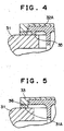
- the present invention can be also be structured as shown in Figs. 3A and 3B.
- a recessed portion 34A or a protruding portion 34B is provided on a plastic part on one side.
- the recessed portion 34A or protruding portion 34B is joined to the metamorphic polyethylene layer 33 (by insert molding or the like) to improve the joining property and airtightness. At the same time, the performance for preventing the part from coming off can be improved.
- the number of recessed portions 34A or protruding portions 34B is not determined in particular, that is, the recessed portion 34A or protruding portion 34B may be a single circular groove (or a projection) or a plurality of circular grooves (or projections).
- the recessed portion 34A or protruding portion 34B may be made a groove or projection formed at an area (locally) rather than an elongated circular groove or projection.
- a stopper 35 may be provided to the plastic part on the one side (the flange portion 32A of the fuel cut valve 32) to extend toward the plastic part on the other side (the fuel tank 31). By abutting the stopper 35 against the plastic part on the other side (the fuel tank 31), indexing of the joined position when joined is made easier, thus joining operation becomes easier.
- a recessed-protruding portion 36 may be provided on the plastic part on the other side (the mounting member 31A of the fuel tank 31) or the metamorphic polyethylene layer 33.
- the joining property and airtightness can be improved together with the performance for preventing the part from coming off.
- the number of the recessed-protruding portions 36 is not determined in particular.
- the recessed-protruding portion 36 may be a single circular groove (or a projection) or a plurality of circular grooves (or projections).
- the shape of the projection various shapes may be employed, such as a saw-tooth shaped projection, in addition to the rectangular projection or groove as shown in the figure.
- the recessed-protruding portion 36 may be made a groove or projection formed at an area (locally) rather than an elongated circular groove or projection.
Abstract
Description
Claims (8)
- A joining structure characterized by comprising:a first plastic part (21) composed of at least one thermoplastic resin of polyamide (PA), polybutylene terephthalate (PBT), polyacetal (POM), polyethylene terephthalate (PET), or polyphenylene sulfide (PPS);a second plastic part (22) composed of at least high-density polyethylene (HDPE); anda metamorphic polyethylene layer (23) that comes in contact with both the first plastic part (21) and the second plastic part (22), for joining the first plastic part (21) and the second plastic part (22).
- A joining structure according to claim 1, characterized in that
the first plastic part (21) is composed of a reinforced thermoplastic resin. - A joining structure according to claim 1 or 2, characterized in that
the metamorphic polyethylene layer (23) is interposed between the first plastic part (21) and the second plastic part (22). - A joining structure according to any one of claims 1 to 3, characterized in that
the first plastic part (21) is at least a part of a fuel cutoff valve casing, and the second plastic part (22) is at least a part of a mounting portion of a plastic fuel tank. - A joining structure according to any one of claims 1 to 3, characterized in that
the first plastic part (21) is at least a part of an onboard refueling vapor recovery valve casing, and the second plastic part (22) is at least a part of the mounting portion of a plastic fuel tank. - A joining structure according to any one of claims 1 to 5, characterized in that
the first plastic part (21) has at least one of either a recessed portion (34A) or a protruding portion (34B), and the metamorphic polyethylene layer (23) has at least one of either a recessed portion or a protruding portion to engage with at least one of either the recessed portion (34A) or the protruding portion (34B) provided on the first plastic part (21). - A joining structure according to any one of claims 1 to 5, characterized in that
the second plastic part (22) has at least one of either a recessed portion or a protruding portion (36), and the metamorphic polyethylene layer (23) has at least one of either a recessed portion or a protruding portion to engage with at least one of either the recessed portion or the protruding portion (36) provided on the second plastic part (22). - A joining structure according to any one of claims 1 to 7, characterized in that
the first plastic part (21) has a stopper (35) extending toward the second plastic part (22), and the end portion of the stopper (35) abuts against the second plastic part (22) upon joining of the first plastic part (21) and the second plastic part (22).
Applications Claiming Priority (2)
| Application Number | Priority Date | Filing Date | Title |
|---|---|---|---|
| JP2000106957A JP2001287269A (en) | 2000-04-07 | 2000-04-07 | Bonding structure of resin part |
| JP2000106957 | 2000-04-07 |
Publications (2)
| Publication Number | Publication Date |
|---|---|
| EP1142935A2 true EP1142935A2 (en) | 2001-10-10 |
| EP1142935A3 EP1142935A3 (en) | 2002-05-15 |
Family
ID=18620036
Family Applications (1)
| Application Number | Title | Priority Date | Filing Date |
|---|---|---|---|
| EP01108729A Withdrawn EP1142935A3 (en) | 2000-04-07 | 2001-04-06 | Plastic parts joining structure |
Country Status (3)
| Country | Link |
|---|---|
| US (1) | US6475625B2 (en) |
| EP (1) | EP1142935A3 (en) |
| JP (1) | JP2001287269A (en) |
Cited By (6)
| Publication number | Priority date | Publication date | Assignee | Title |
|---|---|---|---|---|
| EP1203685A1 (en) * | 2000-11-02 | 2002-05-08 | Nifco Inc. | Fuel tank connector |
| US6475625B2 (en) * | 2000-04-07 | 2002-11-05 | Kyosan Denki Co., Ltd. | Plastic parts joining structure |
| EP1323973A3 (en) * | 2001-12-28 | 2004-02-11 | Degussa AG | Fluid or steam conveying system with a weld seam made from a coextruded laminate |
| WO2005007441A1 (en) * | 2003-07-11 | 2005-01-27 | Alfmeier Präzision AG | Fuel tank and method for production thereof |
| WO2005072937A1 (en) * | 2004-01-05 | 2005-08-11 | Eaton Corporation | Attaching dissimilar materials to a fuel tank by weldment |
| WO2005077653A1 (en) * | 2004-02-11 | 2005-08-25 | Ticona Llc | Fuel container having contiguous unbonded polyacetal/polyolefin layers |
Families Citing this family (11)
| Publication number | Priority date | Publication date | Assignee | Title |
|---|---|---|---|---|
| JP2002242783A (en) * | 2001-02-20 | 2002-08-28 | Tokai Rubber Ind Ltd | Tank joining part |
| JP2003205755A (en) * | 2002-01-11 | 2003-07-22 | Unipres Corp | Connection tube structure for connecting filler tube to fuel tank |
| CA2433221A1 (en) * | 2002-07-12 | 2004-01-12 | Betts Industries, Inc. | Hydraulic actuated vapor recovery valve |
| US6619331B1 (en) * | 2002-11-20 | 2003-09-16 | Jagan N. Suchdev | Water delivery tube assembly |
| FR2860279B1 (en) * | 2003-09-26 | 2008-11-28 | Inergy Automotive Systems Res | SEALED COMPOSITE CONDUIT, PROCESS FOR MANUFACTURING THE SAME AND SYSTEM FOR SUPPLYING AN INTERNAL COMBUSTION ENGINE |
| CN1763408A (en) * | 2004-10-22 | 2006-04-26 | 东海橡胶工业株式会社 | Welding joint of fuel tank |
| US20070163651A1 (en) * | 2006-01-19 | 2007-07-19 | Eaton Corporation | Fuel tank component with weldable connector |
| JP5396788B2 (en) * | 2008-09-17 | 2014-01-22 | 宇部興産株式会社 | Composite structure and manufacturing method thereof |
| JP5352413B2 (en) * | 2009-10-20 | 2013-11-27 | 株式会社ニフコ | Fuel tank connector |
| JP6895540B2 (en) * | 2017-11-30 | 2021-06-30 | 本田技研工業株式会社 | Resin tank |
| JP6777957B1 (en) * | 2019-12-03 | 2020-10-28 | 株式会社日豊製作所 | Joined hollow molded product |
Citations (4)
| Publication number | Priority date | Publication date | Assignee | Title |
|---|---|---|---|---|
| DE3524881A1 (en) * | 1985-07-12 | 1987-01-22 | Elkamet Werk | Vessel for liquids, in particular fuel tank made of thermoplastic and process for the production thereof |
| EP0626256A1 (en) * | 1993-05-24 | 1994-11-30 | Mitsubishi Chemical Corporation | Hollow multi-layer molding |
| US5424020A (en) * | 1989-08-21 | 1995-06-13 | Sumitomo Chemical Company, Limited | Method for producing molded article of fiber-reinforced thermoplastic resin |
| DE19535413C1 (en) * | 1995-09-23 | 1996-10-02 | Rasmussen Gmbh | Tube-like nozzle for connection to vessel of HDPE with thermoplastic part |
Family Cites Families (4)
| Publication number | Priority date | Publication date | Assignee | Title |
|---|---|---|---|---|
| DE69122274T2 (en) * | 1990-06-15 | 1997-02-20 | Tonen Sekiyukagaku Kk | Process for producing a multi-layer plastic fuel tank |
| DE4239909C1 (en) | 1992-11-27 | 1994-05-05 | Rasmussen Gmbh | Tubular plastic connector for flexible lines - comprises fibre reinforced first part with low creep, injected onto unreinforced second part |
| JP3386984B2 (en) | 1992-12-14 | 2003-03-17 | 株式会社ニフコ | Fuel spill prevention valve |
| JP2001287269A (en) * | 2000-04-07 | 2001-10-16 | Kyosan Denki Kk | Bonding structure of resin part |
-
2000
- 2000-04-07 JP JP2000106957A patent/JP2001287269A/en active Pending
-
2001
- 2001-04-05 US US09/825,844 patent/US6475625B2/en not_active Expired - Fee Related
- 2001-04-06 EP EP01108729A patent/EP1142935A3/en not_active Withdrawn
Patent Citations (4)
| Publication number | Priority date | Publication date | Assignee | Title |
|---|---|---|---|---|
| DE3524881A1 (en) * | 1985-07-12 | 1987-01-22 | Elkamet Werk | Vessel for liquids, in particular fuel tank made of thermoplastic and process for the production thereof |
| US5424020A (en) * | 1989-08-21 | 1995-06-13 | Sumitomo Chemical Company, Limited | Method for producing molded article of fiber-reinforced thermoplastic resin |
| EP0626256A1 (en) * | 1993-05-24 | 1994-11-30 | Mitsubishi Chemical Corporation | Hollow multi-layer molding |
| DE19535413C1 (en) * | 1995-09-23 | 1996-10-02 | Rasmussen Gmbh | Tube-like nozzle for connection to vessel of HDPE with thermoplastic part |
Cited By (10)
| Publication number | Priority date | Publication date | Assignee | Title |
|---|---|---|---|---|
| US6475625B2 (en) * | 2000-04-07 | 2002-11-05 | Kyosan Denki Co., Ltd. | Plastic parts joining structure |
| EP1203685A1 (en) * | 2000-11-02 | 2002-05-08 | Nifco Inc. | Fuel tank connector |
| EP1291223A2 (en) * | 2000-11-02 | 2003-03-12 | Nifco Inc. | Fuel tank connector |
| EP1291223A3 (en) * | 2000-11-02 | 2003-04-16 | Nifco Inc. | Fuel tank connector |
| US6733048B2 (en) | 2000-11-02 | 2004-05-11 | Nifco, Inc. | Fuel tank connector |
| US7090262B2 (en) | 2000-11-02 | 2006-08-15 | Nifco, Inc. | Fuel tank connector |
| EP1323973A3 (en) * | 2001-12-28 | 2004-02-11 | Degussa AG | Fluid or steam conveying system with a weld seam made from a coextruded laminate |
| WO2005007441A1 (en) * | 2003-07-11 | 2005-01-27 | Alfmeier Präzision AG | Fuel tank and method for production thereof |
| WO2005072937A1 (en) * | 2004-01-05 | 2005-08-11 | Eaton Corporation | Attaching dissimilar materials to a fuel tank by weldment |
| WO2005077653A1 (en) * | 2004-02-11 | 2005-08-25 | Ticona Llc | Fuel container having contiguous unbonded polyacetal/polyolefin layers |
Also Published As
| Publication number | Publication date |
|---|---|
| US6475625B2 (en) | 2002-11-05 |
| EP1142935A3 (en) | 2002-05-15 |
| JP2001287269A (en) | 2001-10-16 |
| US20010028939A1 (en) | 2001-10-11 |
Similar Documents
| Publication | Publication Date | Title |
|---|---|---|
| US6475625B2 (en) | Plastic parts joining structure | |
| JP4657496B2 (en) | Flange seal assembly | |
| EP0930190B1 (en) | Hollow resin container | |
| US6499500B2 (en) | Motor vehicle fuel tank | |
| US8033415B2 (en) | Structure of opening section of fuel tank | |
| KR101103912B1 (en) | Flapper type fill tube check valve | |
| US8668176B2 (en) | Part fixing structure to resin-made fuel tank and part fixing method thereto | |
| US20050199634A1 (en) | Structure and method of insert mold | |
| US7955675B2 (en) | Weld joint for fuel tank | |
| US6808209B2 (en) | Attachment to be attached to fuel tank | |
| JP2009137488A (en) | Fuel tank | |
| JP2001206076A (en) | Fuel tank made of synthetic resin | |
| EP2003007B1 (en) | Connector for fuel tank | |
| US20080164255A1 (en) | Conducting System For a Filling Pipe | |
| EP1197373A2 (en) | Plastic parts connected to a plastic fuel tank | |
| US20040069782A1 (en) | Filler neck | |
| US20070163651A1 (en) | Fuel tank component with weldable connector | |
| JP2004124903A (en) | Tube connection port of fuel tank | |
| JP2002276882A (en) | Structure for mounting cylindrical body on fuel tank | |
| JP2008168766A (en) | Nipple fixing structure for fuel tank | |
| JP2005029100A (en) | Nipple fixing unit for fuel tank of automobile | |
| US6497243B1 (en) | Assembly of fuel system components on a fuel tank | |
| US6371325B1 (en) | Fuel tank closure with cap-ejector spring | |
| JP2009120049A (en) | Nipple mounting structure of fuel tank | |
| JP4495808B2 (en) | Fuel tank opening mounting body |
Legal Events
| Date | Code | Title | Description |
|---|---|---|---|
| PUAI | Public reference made under article 153(3) epc to a published international application that has entered the european phase |
Free format text: ORIGINAL CODE: 0009012 |
|
| 17P | Request for examination filed |
Effective date: 20010502 |
|
| AK | Designated contracting states |
Kind code of ref document: A2 Designated state(s): AT BE CH CY DE DK ES FI FR GB GR IE IT LI LU MC NL PT SE TR |
|
| AX | Request for extension of the european patent |
Free format text: AL;LT;LV;MK;RO;SI |
|
| PUAL | Search report despatched |
Free format text: ORIGINAL CODE: 0009013 |
|
| AK | Designated contracting states |
Kind code of ref document: A3 Designated state(s): AT BE CH CY DE DK ES FI FR GB GR IE IT LI LU MC NL PT SE TR |
|
| AX | Request for extension of the european patent |
Free format text: AL;LT;LV;MK;RO;SI |
|
| RIC1 | Information provided on ipc code assigned before grant |
Free format text: 7C 08J 5/12 A, 7C 09J 123/06 B, 7C 09K 3/10 B, 7B 60K 15/03 B, 7B 60K 15/01 - |
|
| AKX | Designation fees paid | ||
| STAA | Information on the status of an ep patent application or granted ep patent |
Free format text: STATUS: THE APPLICATION IS DEEMED TO BE WITHDRAWN |
|
| 18D | Application deemed to be withdrawn |
Effective date: 20021116 |