EP1142739A1 - Vehicle reinforcement for hollow structural member, having decreasing-thickness end portions - Google Patents
Vehicle reinforcement for hollow structural member, having decreasing-thickness end portions Download PDFInfo
- Publication number
- EP1142739A1 EP1142739A1 EP01116939A EP01116939A EP1142739A1 EP 1142739 A1 EP1142739 A1 EP 1142739A1 EP 01116939 A EP01116939 A EP 01116939A EP 01116939 A EP01116939 A EP 01116939A EP 1142739 A1 EP1142739 A1 EP 1142739A1
- Authority
- EP
- European Patent Office
- Prior art keywords
- reinforcement
- thickness
- decreasing
- portions
- body portion
- Prior art date
- Legal status (The legal status is an assumption and is not a legal conclusion. Google has not performed a legal analysis and makes no representation as to the accuracy of the status listed.)
- Withdrawn
Links
Images


Classifications
-
- B—PERFORMING OPERATIONS; TRANSPORTING
- B60—VEHICLES IN GENERAL
- B60J—WINDOWS, WINDSCREENS, NON-FIXED ROOFS, DOORS, OR SIMILAR DEVICES FOR VEHICLES; REMOVABLE EXTERNAL PROTECTIVE COVERINGS SPECIALLY ADAPTED FOR VEHICLES
- B60J5/00—Doors
- B60J5/04—Doors arranged at the vehicle sides
- B60J5/042—Reinforcement elements
- B60J5/0422—Elongated type elements, e.g. beams, cables, belts or wires
- B60J5/0437—Elongated type elements, e.g. beams, cables, belts or wires characterised by the attachment means to the door, e.g. releasable attachment means
-
- B—PERFORMING OPERATIONS; TRANSPORTING
- B21—MECHANICAL METAL-WORKING WITHOUT ESSENTIALLY REMOVING MATERIAL; PUNCHING METAL
- B21C—MANUFACTURE OF METAL SHEETS, WIRE, RODS, TUBES OR PROFILES, OTHERWISE THAN BY ROLLING; AUXILIARY OPERATIONS USED IN CONNECTION WITH METAL-WORKING WITHOUT ESSENTIALLY REMOVING MATERIAL
- B21C23/00—Extruding metal; Impact extrusion
- B21C23/02—Making uncoated products
- B21C23/20—Making uncoated products by backward extrusion
- B21C23/205—Making products of generally elongated shape
-
- B—PERFORMING OPERATIONS; TRANSPORTING
- B21—MECHANICAL METAL-WORKING WITHOUT ESSENTIALLY REMOVING MATERIAL; PUNCHING METAL
- B21C—MANUFACTURE OF METAL SHEETS, WIRE, RODS, TUBES OR PROFILES, OTHERWISE THAN BY ROLLING; AUXILIARY OPERATIONS USED IN CONNECTION WITH METAL-WORKING WITHOUT ESSENTIALLY REMOVING MATERIAL
- B21C37/00—Manufacture of metal sheets, bars, wire, tubes or like semi-manufactured products, not otherwise provided for; Manufacture of tubes of special shape
- B21C37/06—Manufacture of metal sheets, bars, wire, tubes or like semi-manufactured products, not otherwise provided for; Manufacture of tubes of special shape of tubes or metal hoses; Combined procedures for making tubes, e.g. for making multi-wall tubes
- B21C37/15—Making tubes of special shape; Making tube fittings
- B21C37/28—Making tube fittings for connecting pipes, e.g. U-pieces
-
- B—PERFORMING OPERATIONS; TRANSPORTING
- B21—MECHANICAL METAL-WORKING WITHOUT ESSENTIALLY REMOVING MATERIAL; PUNCHING METAL
- B21K—MAKING FORGED OR PRESSED METAL PRODUCTS, e.g. HORSE-SHOES, RIVETS, BOLTS OR WHEELS
- B21K1/00—Making machine elements
- B21K1/14—Making machine elements fittings
- B21K1/16—Making machine elements fittings parts of pipe or hose couplings
-
- B—PERFORMING OPERATIONS; TRANSPORTING
- B21—MECHANICAL METAL-WORKING WITHOUT ESSENTIALLY REMOVING MATERIAL; PUNCHING METAL
- B21K—MAKING FORGED OR PRESSED METAL PRODUCTS, e.g. HORSE-SHOES, RIVETS, BOLTS OR WHEELS
- B21K21/00—Making hollow articles not covered by a single preceding sub-group
-
- B—PERFORMING OPERATIONS; TRANSPORTING
- B21—MECHANICAL METAL-WORKING WITHOUT ESSENTIALLY REMOVING MATERIAL; PUNCHING METAL
- B21K—MAKING FORGED OR PRESSED METAL PRODUCTS, e.g. HORSE-SHOES, RIVETS, BOLTS OR WHEELS
- B21K21/00—Making hollow articles not covered by a single preceding sub-group
- B21K21/08—Shaping hollow articles with different cross-section in longitudinal direction, e.g. nozzles, spark-plugs
-
- B—PERFORMING OPERATIONS; TRANSPORTING
- B60—VEHICLES IN GENERAL
- B60J—WINDOWS, WINDSCREENS, NON-FIXED ROOFS, DOORS, OR SIMILAR DEVICES FOR VEHICLES; REMOVABLE EXTERNAL PROTECTIVE COVERINGS SPECIALLY ADAPTED FOR VEHICLES
- B60J5/00—Doors
- B60J5/04—Doors arranged at the vehicle sides
- B60J5/042—Reinforcement elements
- B60J5/0422—Elongated type elements, e.g. beams, cables, belts or wires
- B60J5/0438—Elongated type elements, e.g. beams, cables, belts or wires characterised by the type of elongated elements
- B60J5/0443—Beams
- B60J5/0444—Beams characterised by a special cross section
-
- B—PERFORMING OPERATIONS; TRANSPORTING
- B62—LAND VEHICLES FOR TRAVELLING OTHERWISE THAN ON RAILS
- B62D—MOTOR VEHICLES; TRAILERS
- B62D21/00—Understructures, i.e. chassis frame on which a vehicle body may be mounted
-
- B—PERFORMING OPERATIONS; TRANSPORTING
- B62—LAND VEHICLES FOR TRAVELLING OTHERWISE THAN ON RAILS
- B62D—MOTOR VEHICLES; TRAILERS
- B62D21/00—Understructures, i.e. chassis frame on which a vehicle body may be mounted
- B62D21/09—Means for mounting load bearing surfaces
-
- B—PERFORMING OPERATIONS; TRANSPORTING
- B21—MECHANICAL METAL-WORKING WITHOUT ESSENTIALLY REMOVING MATERIAL; PUNCHING METAL
- B21H—MAKING PARTICULAR METAL OBJECTS BY ROLLING, e.g. SCREWS, WHEELS, RINGS, BARRELS, BALLS
- B21H7/00—Making articles not provided for in the preceding groups, e.g. agricultural tools, dinner forks, knives, spoons
- B21H7/18—Making articles not provided for in the preceding groups, e.g. agricultural tools, dinner forks, knives, spoons grooved pins; Rolling grooves, e.g. oil grooves, in articles
- B21H7/187—Rolling helical or rectilinear grooves
Definitions
- the present invention relates in general to a hollow structural member of a body structure preferably of a motor vehicle, and more particularly to such a hollow structural member provided with an internal reinforcement.
- the body structure of a motor vehicle includes various stationary hollow structural members each of which includes a hollow body portion such as tubular body portion.
- These hollow structural members include impact beams, side door waists, center pillars and front pillars.
- the mechanical strength of each hollow structural member can be increased by a reinforcement disposed inside the body portion.
- the impact beam disposed within a side door of a passenger vehicle is provided to minimize inward deformation of the side door due to an impact load applied thereto laterally of the vehicle body upon collision of the vehicle at the side door with a given object.
- the impact beam includes a tubular body portion having a circular transverse cross sectional shape, and a pair of fixing portions integrally fixed to the longitudinal opposite ends of the body portion.
- the impact beam is fixedly attached at its fixing portions to the frame of the side door, such that the body portion of the impact beam extends in the longitudinal or running direction of the vehicle.
- an impact beam of the type in which a reinforcement is disposed inside a longitudinal central part of the tubular body portion, in order to increase the bending strength of the central part so as to prevent buckling thereof, while minimizing an increase in the weight of the impact beam.
- Examples of this type of impact beam are disclosed in JP-A-4-238727 and JP-6-91325, which use a tubular reinforcement or a cylindrical solid reinforcement.
- the buckling of the impact beam is interpreted to mean bending of the tubular body portion into a curved flattened shape due to an impact load laterally applied thereto.
- the bending strength is a value of the load at which the buckling or fracture of the impact beam occurs.
- the bending strength or rigidity considerably changes at and near the opposite ends of a reinforcement provided in the tubular body portion, so that the stress tends to be concentrated around the ends of the reinforcement, increasing a possibility of cracking or fracture at the corresponding parts of the tubular body portion.
- the conventional tubular structural member suffers from a problem of insufficient improvement in the bending strength.
- a test on an impact beam 10' (not provided with a reinforcement) using a pendulum 30 as shown in Fig. 30 revealed a stress distribution as indicated in the graph of Fig. 10.
- the end face of the pendulum 30 was forced onto the impact beam 10', at a longitudinal center point S of the impact beam 10'.
- a FEM (finite-element method) analysis showed the stress distribution of Fig. 10 in which the stress continuously decreases in the opposite longitudinal directions of the impact beam 10', with an increase in the distance from the point (S) of application of the load, as indicated at (1) through (4) in Fig. 9.
- the stress has a maximum value ⁇ max at the load application point or center point S.
- WO 94/13503 JP-T-7-506067 discloses the use of a reinforcement in the form of a generally elongate plate whose width dimension decreases in the longitudinal opposite directions toward its opposite ends, with a decrease in the bending moment applied to the elongate plate. This reinforcement also suffers from considerable changes of the bending strength around the longitudinal ends of the elongate plate. Further, the elongate plate whose width dimension is still comparatively large at the longitudinal ends tends to have cracking due to stress concentration at its end portions.
- a second object of the invention is to provide such a reinforcement for use with a hollow structural member of a body structure, more particularly of a body structure of a motor vehicle.
- the first object indicated above may be achieved according to a first aspect of this invention, which provides a hollow structural member comprising a hollow body portion fixedly disposed on a motor vehicle, the hollow structural member further comprising a reinforcement having a hollow structure which has an outer surface and which is fixedly disposed within the hollow body portion having an inner surface such that the outer surface of the hollow structure is in substantially close contact with the inner surface of the hollow body portion, and wherein the reinforcement includes a longitudinally central portion having highest bending rigidity, and longitudinally opposite end portions each having bending rigidity which continuously decreases in a longitudinal direction from the longitudinally central portion toward a longitudinal end of a corresponding one of the longitudinally opposite end portions, such that the bending rigidity at the longitudinal end is substantially zero.
- the hollow structural member according to the first aspect of this invention comprises the reinforcement including the longitudinally central portion having a higher degree of bending rigidity than the other portion, and the longitudinally opposite end portions each of which has bending rigidity that continuously decreases in the longitudinal direction from the central portion toward the longitudinal end of the corresponding end portion, such that the bending rigidity is substantially zero at the longitudinal end of each end portion. Therefore, the hollow structural member provides a sufficient degree of buckling resistance at the central portion of the reinforcement, and does not suffer from stress concentration around the opposite ends of the reinforcement, whereby the structural member used as an impact beam for a side door of the vehicle has an effectively improved and practically sufficient bending strength, while minimizing the amounts of increase in the weight and cost of the structural member due to the provision of the reinforcement.
- the reinforcement constructed as described above has a relatively high degree of freedom in the choice of its material, and may be suitably formed of a light metal alloy such as an aluminum alloy, making it possible to further reduce the weight of the structural member.
- the first object may also be achieved according to a second aspect of this invention, which provides a hollow structural member fixedly disposed on a motor vehicle, the hollow structural member further comprising a reinforcement having a hollow structure which has an outer surface and which is fixedly disposed within the hollow body portion having an inner surface such that the outer surface of the hollow structure is in substantially close contact with the inner surface of the hollow body portion, and wherein the reinforcement includes a thick-walled portion as a longitudinal central portion thereof, and two decreasing-thickness portions as longitudinally opposite end portions thereof disposed on opposite sides of the thick-walled portion.
- Each of the two decreasing-thickness portions has an inner surface which is formed such that a wall thickness of each decreasing-thickness portion continuously decreases in a longitudinal direction from the thick-walled portion toward a longitudinal end of a corresponding one of the longitudinally opposite end portions and such that the wall thickness at the longitudinal end is substantially zero.
- the hollow structural member according to the second aspect of the invention may be considered to be one form of the hollow structural member according to the first aspect of the invention.
- the hollow structure member according to the second aspect comprises the longitudinally central thick-walled portion, and the longitudinally opposite decreasing-thickness end portions each having the wall thickness which continuously decreases in the longitudinal direction from the thick-walled central portion toward the longitudinal end of the corresponding end portion of the reinforcement, such that the wall thickness is substantially zero at the longitudinal end of each end portion of the reinforcement.
- the present hollow structural member has substantially the same advantages as described above with the hollow structural member according to the first aspect of the invention.
- the hollow body portion of the hollow structural member is preferably a generally tubular member, as discussed below, but may be a hollow member having a polygonal shape in transverse cross section. Where the hollow body portion is a generally tubular member, the tubular member preferably has a substantially circular transverse cross sectional shape. However, the tubular body portion may have an elliptical or oval shape in transverse cross section.
- the hollow body portion may be a tube commercially available, it may be formed by bending a suitable straight metal plate into a tube such that the opposite edges of the plate are butted together, and then seam welding the tube along the butted edges, by arc welding, for example.
- the metal plate may be a steel plate whose tensile strength is as high as about 130kgf/mm 2 . It is noted that 1kgf/mm 2 is approximately equal to 9.8N/mm 2 .
- the hollow body portion is generally fixed at its longitudinal opposite ends to the frame of the side door, through respective fixing portions, such that the hollow structural member extends in the longitudinal or running direction of the vehicle.
- the fixing portions may be separate parts fixed to the opposite ends of the hollow body portion by welding, for example, the fixing portions may be integrally formed with the body portion.
- the body portion is formed from a straight metal plate, for instance, the fixing portions may be formed by bending appropriate portions of the plate while the body portion is formed into a hollow structure.
- the hollow body portion such as an impact beam may be formed integrally with the frame or other part of the vehicle member such as a side door.
- the reinforcement disposed within the hollow body portion may preferably be formed of a metal material such as a carbon steel (e.g., S45C, JIS) or an aluminum alloy (e.g., A5056, JIS).
- the reinforcement may be formed of any other materials such as FRP (fiber-reinforced plastics) or other composite material. It is desirable that the reinforcement be fixedly disposed within a longitudinally central portion of the hollow body portion (e.g., impact beam), by suitable means such as press-fitting, bonding with an adhesive agent, and welding.
- the bending rigidity of the reinforcement is adjusted by suitably changing the wall thickness of the reinforcement in the longitudinal direction.
- the bending rigidity may be adjusted by cutting slits the reinforcement at its appropriate positions so as to extend in the longitudinal direction, or by using different materials at different longitudinal portions of the reinforcement.
- the reinforcement is preferably formed symmetrically with respect to the centerline so that the wall thickness at any longitudinal position is constant around the centerline.
- the reinforcement may be formed asymmetrically with respect to the centerline, so as to follow the asymmetric stress distribution.
- the reinforcement may be formed such that the wall thickness on one side of the centerline remote from the point of application of the impact load is smaller than that on the other side, or such that the longitudinal dimension is shorter on the above-indicated one side.
- the reinforcement is preferably symmetrical with respect to its longitudinally central portion (thick-walled portion), but may be asymmetric with respect to the central portion.
- the wall thickness value at the opposite ends of the reinforcement is desirably as small as substantially zero.
- the wall thickness value at the opposite ends need not be zero, but may be small enough to prevent the cracking or fracture of the structural member at the desired maximum load, for example, 2400kgf or 2700kgf, when the structural member is subjected, at its portion corresponding to the reinforcement, to an impact load as applied by a testing apparatus as shown n Fig. 4.
- the wall thickness values at the opposite ends of the reinforcement may be suitably determined depending upon the desired maximum amount of energy absorption (e.g., about 200kgf ⁇ m or about 250kgf ⁇ m) or the desired average load (e.g., about 1200kgf or about 1350kgf).
- the rate of decrease of the wall thickness and the longitudinal dimension of each decreasing-thickness end portion are also desirably determined so as to satisfy the requirement indicated above, and the wall thickness and the longitudinal dimension of the thick-walled central portion are desirably determined so as to prevent buckling of the structural member under the condition described above.
- the wall thickness value at the opposite ends of the reinforcement for satisfying the above requirement varies depending upon the bending rigidity (material, wall thickness and diameter) of the hollow body portion.
- the reinforcement is formed of a carbon steel (e.g., S45C, JIS) usually used for a structural member
- the wall thickness at the opposite ends of the reinforcement is preferably about 0.5mm or smaller, or about 0.3mm or smaller.
- the reinforcement is formed of an aluminum alloy (e.g., A5056, JIS)
- the wall thickness is preferably about 0.8mm or smaller or about 0.6mm or smaller.
- the thick-walled portion consists of at least one solid partition wall each of which separates a space within the hollow structure of the reinforcement into two longitudinal sections.
- the hollow structural member has a sufficient degree of buckling resistance.
- the hollow body portion has a generally tubular structure
- the reinforcement has a generally tubular structure having an outer surface in substantially close contact with an inner surface of the generally tubular structure of the hollow body portion.
- the thick-walled portion consists of at least one solid partition wall each of which separates a space within the generally tubular structure of the reinforcement into two longitudinal sections, and each decreasing-thickness portion has an inside diameter which increases in the longitudinal direction from the thick-walled portion toward the longitudinal end, so that the wall thickness of each decreasing-thickness portion linearly decreases in the longitudinal direction.
- the solid partition wall permits the tubular structural member to provide a sufficient degree of buckling resistance, while the decreasing-thickness portions whose wall thickness linearly decrease as described above are relatively easy to manufacture.
- each decreasing-thickness portion increases in the longitudinal direction from the thick-walled portion toward the corresponding longitudinal end of the reinforcement, so that the wall thickness linearly decreases in this longitudinal direction.
- the wall thickness may be determined so as to change following the stress distribution on the hollow structural member upon application of an impact load thereto in the lateral direction.
- the thick-walled portion has a wall thickness which non-linearly changes according to a stress distribution on the hollow body portion when the the hollow body portion is subject to an impact load upon collision of the motor vehicle.
- the non-linear change of the wall thickness of the thick-walled portion permits the structural member to have an effectively improved strength, while minimizing the amounts of increase in the weight and cost of the structural member due to the provision of the reinforcement.
- each solid partition wall has opposite part-spherical surfaces each of which has a curvature having a center lying on a centerline of the generally tubular structure of each reinforcement, and each part-spherical surface is smoothly contiguous with the inner surfaces of the two decreasing-thickness portions.
- the hollow structural member has bending rigidity characteristic similar to a stress distribution (as shown in Figs. 9 and 10) on the structural member when the hollow body portion is subjected to an impact load upon collision of the vehicle.
- the present structural member has an effectively improved strength, with minimum amounts of increase in the weight and cost of the structural member due to the provision of the reinforcement.
- This arrangement may be considered as one arrangement of the third preferred form of the invention described above. It is also noted that the part-spherical surfaces of the partition wall whose curvatures lie on the centerline of the reinforcement are relatively easy to form. In addition, the smooth connection of the part-spherical surfaces to the inner surfaces of the decreasing-thickness portions results in a continuous decrease of the wall thickness of the reinforcement in the longitudinal direction from the partition wall to the decreasing-thickness end portions. In this case, the reinforcement may be easily formed with a relatively low cost, in a process including a forging step wherein a blank is forged into a plate from which the reinforcement is formed.
- the stress distribution indicated above which changes with the specific types, material, wall thickness, diameter and length of the hollow structural member, may be obtained for the specific structural member in question, by a suitable method such as FEM (finite-element method) analysis.
- FEM finite-element method
- the reinforcement further includes two constant-thickness portions formed between the solid partition wall and the two decreasing-thickness portions, each of the constant-thickness portion having a constant wall thickness and cooperating with the solid partifion wall to define therebetween a fillet having a predetermined radius of curvature.
- the longitudinal dimension of each constant-thickness portion is determined depending upon the longitudinal length of the hollow body portion of the structural member, which varies with the specific type or model of the vehicle.
- the reinforcement is formed as an integral part of the hollow body portion.
- a bonding adhesive such as a resin adhesive is not necessary for fixing the reinforcement within the hollow body portion, and the mechanical strength of the structural member is improved, whereby the weight of the structural member is reduced. Further, the required number of process steps for manufacturing the structural member is significantly reduced, leading to reduced cost of its manufacture.
- the structural member may be manufactured in a process comprising the steps of: (a) rolling a blank into a plate corresponding to a development of the hollow structural member in question along a straight line parallel to the centerline of the structural member, the plate having a changing-thickness portion corresponding to the reinforcement portion; (b) forming a plurality or multiplicity of notches in the surface of the changing-thickness portion of the plate, which surface has been shaped by rolling in the above step (a), so that the plate can be bent into a tube such that the above-indicated surface having the notches provides an inner surface of the tube; and (c) bending the notched plate into the tubular structural member which has a tubular reinforcement as an integral part of the tubular body portion.
- the hollow structural member having the integrally formed reinforcement may be formed in other processes including a forging step or a machining step.
- the reinforcement is disposed as an intermediate reinforcement in a longitudinally intermediate portion of the hollow body portion, and the hollow structural member further comprising an end reinforcement having a hollow structure having an outer surface and disposed in at least one of longitudinally opposite end portions of the hollow body portion, such that the outer surface of the hollow structure is in substantially close contact with an inner surface of the hollow body portion.
- the end reinforcement includes a decreasing-thickness portion as one of longitudinally opposite end portions thereof which is on the side of the longitudinally intermediate portion of the hollow body portion.
- the decreasing-thickness portion has an inner surface which is formed such that a wall thickness of the decreasing-thickness portion continuously decreases in a longitudinal direction from the other of the longitudinally opposite end portions toward the above-indicated one of the longitudinally opposite end portions and such that the wall thickness of the end reinforcement is substantially zero at a longitudinal end of the above-indicated one end portion of the decreasing-thickness portion.
- the end reinforcement disposed in at least one of the opposite ends of the hollow body portion increases the buckling resistance and bending strength at a portion of the structural member at which the structural member is fixed through an appropriate fixing portion to a frame or other part of the motor vehicle.
- This end reinforcement cooperates with the intermediate reinforcement to further increase the overall impact resistance and shock absorbing capability of the hollow structural member.
- the decreasing-thickness portion which is provided as a longitudinally inner end portion of the end reinforcement has a wall thickness which continuously decreases in the direction from the outer end toward the inner end of the end reinforcement such that the wall thickness at the inner end of the end reinforcement is substantially zero. This decreasing-thickness portion is effective to prevent stress concentration and consequent cracking or fracture of the body portion near the inner end of the end reinforcement.
- the end reinforcement may be a hollow member which is closed by a bottom portion located at the outer end of the hollow body portion.
- the decreasing-thickness portion is formed adjacent to the bottom portion such that the wall thickness of the decreasing-thickness portion continuously decreases in the longitudinal direction from the closed end (bottom portion) toward the inner open end of the end reinforcement.
- the wall thickness of the bottom portion is suitably determined depending upon the required strength of the bottom portion.
- the bottom portion may have a through-hole, for reducing the weight of the end reinforcement. It will be understood that the end reinforcement need not include such a bottom portion, namely, may be formed so as to have different wall thickness values at the opposite ends.
- the end reinforcement may be provided in only one of the opposite end portions of the body portion, or alternatively in both of the end portions of the body portion of the structural member. In the latter case, the intermediate reinforcement indicated above is disposed between the two end reinforcements.
- the hollow structural member according to the present invention may be suitably used as an impact beam fixedly disposed in a side door of the motor vehicle, so as to extend in a running direction of the vehicle.
- the hollow structural member may be used as any other structural member of the motor vehicle, which may be selected from among a center pillar, a side door waist, a side sill, a front pillar, a front cross member, a front side member and a bumper reinforcing beam of the motor vehicle.
- These structural members are given for illustrative purpose only.
- the second object indicated above may be achieved according to a third aspect of this invention, which provides a reinforcement fixedly disposed in a hollow structural member including a hollow body portion fixedly disposed on a motor vehicle, the reinforcement has a hollow structure which has an outer surface and which is fixedly disposed within the hollow body portion such that the outer surface of the hollow structure is in substantially close contact with an inner surface of the hollow body portion, the reinforcement comprises: (a) a longitudinally central portion having highest bending rigidity; and (b) longitudinally opposite end portions each having bending rigidity which continuously decreases in a longitudinal direction from the longitudinally central portion toward a longitudinal end of a corresponding one of the longitudinally opposite end portions, such that the bending rigidity at the longitudinal end is substantially zero.
- the reinforcement according to the third aspect of the invention has substantially the same advantage as described above with the hollow structure member according to the first aspect of the invention.
- the second object may also be achieved according to a fourth aspect of this invention, which provides a reinforcement fixedly disposed in a hollow structural member including a hollow body portion fixedly disposed on a motor vehicle, the reinforcement has a hollow structure which has an outer surface and which is fixedly disposed within the hollow body portion such that the outer surface of the hollow structure is in substantially close contact with an inner surface of the hollow body portion, the reinforcement comprises: (a) a thick-walled portion as a longitudinal central portion thereof; and (b) two decreasing-thickness portions as longitudinally opposite end portions thereof disposed on opposite sides of the thick-walled portion, each of the two decreasing-thickness portions having an inner surface which is formed such that a wall thickness of each decreasing-thickness portion continuously decreases in a longitudinal direction from the thick-walled portion toward a longitudinal end of a corresponding one of the longitudinally opposite end portions and such that the wall thickness at the longitudinal end is substantially zero.
- the reinforcement according to the fourth aspect of the invention has substantially the same advantage as described above with respect to the hollow structural member according to the second aspect of the invention.
- the reinforcement comprises: (a) a first piece constituting a first part of the thick-walled portion and including a first and a second engaging portion at longitudinally opposite ends thereof; (b) a second piece including one of the two decreasing-thickness portions and constituting a second part of the thick-walled portion which is adjacent to the one of the two decreasing-thickness portions, the second piece including an engaging end portion which is remote from the one of the two decreasing-thickness portions and which engages the second engaging portion of the first piece; and (c) a third piece including the other of the two decreasing-thickness portions and constituting a third part of the thick-walled portion which is adjacent to the other of the two decreasing-thickness portions, the third piece including an engaging end portion which is remote from the other of the two decreasing-thickness portions and which engages the first engaging portion of the first piece, the first, second and third parts constituting the thick-walled portion.
- the reinforcement according to the above preferred form of the fourth aspect of this invention comprises the three different pieces.
- the reinforcement may include two or more first pieces engaging each other such that the first engaging portion of one of the first pieces engages the second engaging portion of the adjacent one of the other first piece or pieces and such that the first and second engaging portions of the two outer first pieces engage the third and second pieces, respectively.
- the longitudinal dimension of the thick-walled portion of the reinforcement can be adjusted by changing the number of the mutually engaging first pieces.
- the present reinforcement is effective to permit the structural member to provide an increased bending rigidity over the desired longitudinal dimension, which changes depending upon the specific length of the body portion of the structural member.
- All of the first, second and third pieces may be formed of the same material.
- the first, second and third pieces may be formed of different materials.
- the second and third pieces having the decreasing-thickness portions which are the opposite end portions of the reinforcement may be formed of a material whose rigidity is lower than that of the first piece.
- the reinforcement may consist of one piece, or a plurality of pieces which are arranged around the centerline of the body portion and assembled together into a reinforcement. It will also be understood that a plurality of reinforcements each consisting of a single piece may be arranged in the longitudinal direction of the body portion, such that the reinforcements are disposed adjacent to each other or in spaced-apart relation with each other.
- the hollow body portion has a generally tubular structure and the thick-walled portion consists of a solid partition wall, as described above with respect to the second preferred form of the second aspect of the invention, and each solid partition wall has opposite part-spherical surfaces each of which has a curvature having a center lying on a centerline of the generally tubular structure of each reinforcement and is smoothly contiguous with the two decreasing-thickness portions.
- the reinforcement is manufactured in a process including a forging step of cold-forging a blank into a plate from which the reinforcement is formed.
- the reinforcement can be more easily and inexpensively manufactured than where the reinforcement is manufactured by machining. Further, the thus manufactured reinforcement has a sufficiently high mechanical strength with a comparatively small wall thickness and an accordingly reduced weight.
- the decreasing-thickness portions have continuously decreasing wall thickness can be comparatively easily formed by forging a suitable blank such as a cylindrical blank, with a relatively small number of forging actions, so that the life of the forging die can be accordingly increased.
- the reinforcement according to the present invention may be manufactured in any other process including a machining step or casting (e.g., aluminum die casting).
- the reinforcement is manufactured in a process including a cold-forging step as described above, the reinforcement is preferably formed of a material which can easily flow during the forging operation.
- FIGs. 1(a), 1(b) and 1(c) there is shown an impact beam 10 of a side door of a motor vehicle, which is constructed according to one embodiment of the present invention. It is noted that the cross sectional view of Fig. 1(c) is enlarged two times with respect to the views of Figs. 1(a) and 1(b).
- the impact beam 10 includes a tubular body portion 12 having a circular transverse cross sectional shape as shown in Fig. 1(c), a pair of fixing portions 14 fixed to the opposite longitudinal ends of the tubular body portion 12, and a reinforcement 16 fixedly disposed within a longitudinally central part of the tubular body portion 12, as indicated in Figs. 1(a) and 1(b).
- the impact beam 10 is attached to a frame of the side door of the vehicle such that the tubular body portion 12 extends in the longitudinal or running direction of the vehicle, while the upper side of the impact beam 10 as seen in Fig. 1(b) faces in the laterally outward direction of the vehicle so that the above-indicated upper side receives a load upon collision of the vehicle at its side door with a certain object.
- the impact beam 10 has an overall length L1 of about 1104mm, and the tubular body portion 12 has a length L2 of about 950mm.
- the end portions of the tubular body portion 12 are inserted into the respective fixing portions 14 over a length W of about 30mm, and are welded to the fixing portions 14 over a length of about 25mm, by arc welding, for example.
- the tubular body portion 12 is formed from a straight rectangular steel plate, for example, a steel plate SPFC1270Y, JIS (Japanese Industrial Standard) having a tensile strength of about 130kgf/mm 2 and a thickness of 1.6mm. Described more specifically, the steel plate is formed into a tubular shape having a high degree of roundness, such that the opposite long-side edges are butted together.
- the thus formed tube is welded by arc welding, for example, at a longitudinally middle section of the tube over a length of 400mm along the butted edges such that the welded section 12a extends over 200mm from a longitudinal center point S of the tube in the opposite longitudinal directions.
- the thus obtained tubular body portion 12 has an outside diameter of about 31.8mm.
- the tubular body portion 12 is fixed to the fixing portions 14 so that the lower side of the body portion 12 as seen in Fig. 1(a) faces in the laterally inward direction of the vehicle.
- Each of the fixing portions 14 is formed from a hot-dip zinc-coated steel plate, for example, steel plate SGC440, JIS having a tensile strength of 45kgf/mm 2 and a thickness of 1.2mm. Described more particularly, the steel plate is formed by pressing into the fixing portion 14 having an opening 14a which has a semi-circular bottom whose radius of curvature is substantially equal to that of the outer circumferential surface of the tubular body portion 12. That is, the width of the opening 14a as measured in the direction perpendicular to the thickness direction of the fixing portion 14 is substantially equal to the outside diameter of the tubular body portion 12.
- the opposite end portions of the tubular body portion 12 are received in the openings 14a of the fixing portions 14 and secured to the fixing portions 14 by arc welding, for example.
- Each fixing portion 14 has a pair of holes 14b, which are pilot holes formed through the steel plate and used in a pressing operation to form the fixing portion 14. These holes 14b are filled by welding.
- the length and position of welding of the welded portion 12a of the tubular body portion 12 may be changed as needed.
- the consultedd portion 12a may be provided over the entire length of the body portion 12.
- the reinforcement 16 is a tubular member which has a circular transverse cross sectional shape as indicated in Figs. 2(b) and 2(c), and an outside diameter substantially equal to the inside diameter of the tubular body portion 12.
- the tubular reinforcement 16 is disposed within the tubular body portion 12 such that the reinforcement is held in close contact at its outer circumferential surface with the inner circumferential surface of the body portion 12.
- the reinforcement 16 includes a thick-walled portion in the form of a solid partition wall 18 formed in a longitudinally or axially central portion thereof such that the partition wall 18 extends in the radial direction, so that the interior of the reinforcement is separated by the partition wall 18 into two longitudinal sections.
- the partition wall 18 has a thickness determined to have give the reinforcement 16 a sufficient degree of bending strength or rigidity. The thickness is the dimension in the longitudinal direction of the reinforcement 16.
- the reinforcement 16 further includes opposite end portions in the form of decreasing-thickness portions 20, 20 each formed over a predetermined length E up to the corresponding outer end such that the two decreasing-thickness portion 20, 20 are symmetrical with each other with the partition wall 18 interposed therebetween in the longitudinal direction of the reinforcement 16.
- Each decreasing-thickness portion 20 has a tapered inner circumferential surface such that the inside diameter increases in the longitudinal direction from the partition wall 18 toward the corresponding outer end, so that the wall thickness of the decreasing-thickness portion 20 linearly decreases in the above-indicated longitudinal direction until the wall thickness is substantially zeroed at the outer end so as to form an edge.
- the reinforcement 16 also includes two constant-thickness portions 22 each formed between the partition wall 18 and the corresponding one of the two decreasing-thickness portions 20 described above.
- Each constant-thickness portion 22 has a constant wall thickness over its entire length in the longitudinal direction of the reinforcement 16. The rate of change or decrease of the wall thickness (taper angle) and the length E of the decreasing-thickness portions 20, and the wall thickness at the outer ends of these portions 20 are determined so that the bending rigidity of the reinforcement 16 smoothly decreases in the longitudinally outward directions and is almost zeroed at the outer ends (edges), in order to avoid cracking or fracture of the tubular body portion 12 due to stress concentration at the end portions of the reinforcement 16.
- annular fillets 23 having a suitable radius of curvature, in order to avoid sudden changes of the bending rigidity of the reinforcement 16 and consequent stress concentration at the parts between the partition wall 18 and the constant-thickness portions 22.
- the reinforcement 16 is symmetrical with respect to its centerline O in all radial directions. Namely, the wall thickness of the reinforcement 16 at any longitudinal position thereof is constant in the circumferential direction. Therefore, the reinforcement 16 can be disposed within the tubular body portion 12, without specific positioning of the reinforcement 16 relative to the tubular body portion 12 in the circumferential direction.
- the wall thickness values of the portions 18, 20, 22 and the radius of curvature of the fillets 23 may be determined as needed depending upon the material of the reinforcement 16.
- the reinforcement 16 is formed of a carbon steel (used for structural members), for example, SC45, JIS, and has the dimensions (in mm) as indicated in Fig. 3 and a weight W of about 122gf.
- the reinforcement 16 may be formed by cold forging or machining.
- the reinforcement 16 is formed by machining, and press-fitted into the tubular body portion 12 through one of the opposite open ends of the body portion 12 before the fixing portions 14 are welded to the body portion 12.
- the reinforcement 16 is press-fitted in the tubular body portion 12
- the reinforcement 16 is positioned in the longitudinal direction relative to the body portion 12, by a suitable positioning jig inserted into the body portion 12 through the other open end of the body portion 12, such that the longitudinal center point (partition wall 18) of the reinforcement 16 is substantially aligned with or located at the longitudinal center point S of the body portion 12, as indicated in Fig. 2(a).
- the reinforcement 16 is fixed in the body portion 12 by means of only an interference fit therebetween.
- the reinforcement 16 may be fixed to the body portion 16 by other means such as welding or a bonding agent such as a resin material.
- the impact beam 10 is reinforced by the reinforcement 16 which has the partition wall 18 at its longitudinally central portion, and the decreasing-thickness portions 20 as the longitudinally opposite end portions each formed over the length E such that the wall thickness of each decreasing-thickness portion 20 linearly decreases in the longitudinally outward direction toward the end so that the thickness at the end is almost zero.
- the reinforcement 16 is fixed at the longitudinally central portion of the tubular body portion 12, so that the impact beam 10 has a sufficiently high buckling resistance around the longitudinal center point S of the body portion 12, and does not suffer from stress concentration around the ends of the reinforcement 16.
- the bending strength of the impact beam 10 is effectively increased to a practically satisfactory value, without considerable amounts of increase in the weight and cost of manufacture of the impact beam 10 due to the provision of the reinforcement 16.
- the thick-walled portion in the form of the partition wall 18 gives the reinforcement 16 a significantly increased resistance to buckling, while the decreasing-thickness portions 20 whose wall thickness value linearly decreases can be comparatively easily and economically formed.
- the constant-thickness portions 22 having a constant wall thickness and formed between the partition wall 18 and the decreasing-thickness portions 20 so as to define the fillets 23 therebetween with a suitable radius of curvature make it possible to give the reinforcement 16 a desired bending rigidity, depending upon the length dimension of the constant-thickness portions 22. Accordingly, by suitably determining the length dimension of the constant-thickness portions 22, the reinforcement 16 can be used for various impact beams 10 whose tubular body portions 12 have different length dimensions.
- a bending test was conducted on the impact beam 10, using a testing apparatus as shown in Fig. 4.
- the impact beam 10 was set on the testing apparatus, by first securing the two fixing portions 14 to respective metal support members 24 by arc welding, and then fastening the support members 24 to a surface plate 26 of the testing apparatus by bolts 29.
- the two support members 24, each of which has a U shape in cross section, were positioned on the surface plate 26 such that the U-shaped openings of the support members 23 are open toward each other.
- the support members 24 are reinforced by respective reinforcing plates 28 secured thereto by arc welding, so as to provide highly rigid support structures 24, 28 which undergo substantially no deformation in the bending test.
- the impact beam 10 was positioned so as to have a substantially horizontal attitude, such that the welded portion 12a of the body portion 12 which is to face in the laterally inward direction of the vehicle when installed on the vehicle is located on the lower side of the impact beam 10 or faces downward.
- the pendulum 30 having a semi-circular cross sectional shape as shown in Fig. 4 was lowered substantially in the vertical direction, onto to the tubular body portion 12 at the longitudinal center point S of the latter.
- the pendulum 30 has a radius of curvature of 152mm and a thickness of 40mm.
- the amount of downward displacement of the body portion 12 at the center point S was measured at different values of the load which acts on the body portion 12 through the pendulum 30.
- the graph of Fig. 5 indicates a relationship between the amount of displacement and the load.
- the pendulum 30 was lowered over its maximum operating stroke of 202.3mm, that is, lowered to its lower stroke end, without fracture or buckling of the impact beam 10.
- the maximum load measured at the lower stroke end of the pendulum 30 was 3367kgf.
- the amount of energy absorption by the impact beam 10 by the time the pendulum 30 was lowered to its lower stroke end was 318.7kgf ⁇ m, and the average load was 1576.9kgf.
- the energy absorption amount is an integral of the load values by the time the pendulum 30 was lowered to a given point (to the lower stroke end in the above case), and the average load is obtained by dividing the energy absorption amount by the displacement.
- the row No. 1 of the table of Fig. 24 also indicates the energy absorption amount and the average load when the displacement was 152mm (6 inches).
- Broken line in the graph of Fig. 5 indicates this displacement value of 152mm.
- FIG. 6 there is shown an impact beam 32 for a side door of a motor vehicle, which is constructed according to a second embodiment of this invention.
- the impact beam 32 is substantially identical in construction with the impact beam 10 of Figs. 1(a)-1(c), except for the provision of an end reinforcement 34 disposed in each of the opposite axial end portions of the tubular body portion 12, in addition to the intermediate reinforcement 16.
- the end reinforcement 34 is shown in enlargement in Figs. 7(a), 7(b) and 7(c).
- This end reinforcement 34 is a tubular member which has an outside diameter substantially equal to the inside diameter of the tubular body portion 12.
- the end reinforcement 34 is disposed such that its outer circumferential surface is held in substantially close contact with the inner circumferential surface of the tubular body portion 12.
- the tubular member of the end reinforcement 34 is closed by a bottom portion 36 at one axial end thereof, which closes the corresponding end of the tubular body portion 12.
- the bottom portion 36 has a wall thickness determined to have a desired bending rigidity or strength.
- the end reinforcement 34 further has a decreasing-thickness portion 38 whose inner circumferential surface is tapered such that the wall thickness linearly decreases in the axial direction from the bottom portion 36 at the above-indicated one axial end toward the other open inner axial end, namely, toward the axially central portion of the body portion 12.
- the thickness of the decreasing-thickness portion 38 is substantially zero at the inner axial end.
- the rate of decrease of the wall thickness (taper angle) of the decreasing-thickness portion 38 and the thickness at the inner axial end of the portion 38 are determined so that the bending rigidity or strength smoothly decreases in the above-indicated axial direction such that the bending rigidity at the inner axial end of the portion 38 is substantially zero, in order to prevent cracking or fracture of the tubular body portion 12 due to stress concentration around the inner axial end of the portion 38.
- the end reinforcement 34 is secured within the body portion 12 by suitable means such as a bonding adhesive such that the outer end surface of the bottom portion 36 is substantially flush with the corresponding end face of the body portion 12.
- the axial dimension of the end reinforcement 34 is determined so that its inner end is spaced from the inner end of the corresponding fixing portion 14 by a suitable distance in the axial direction toward the central portion of the body portion 12.
- the end reinforcement 34 is formed of a material similar to that of the reinforcement 16.
- the end reinforcement 34 is formed of a carbon steel generally used for structural members.
- each end reinforcement 34 is a tubular member including the bottom portion 36 at its one axial end and the decreasing-thickness portion 38 whose wall thickness linearly decreases in the axial direction from the bottom portion 36 toward the other or inner axial end such that the wall thickness at the inner axial end is substantially zero.
- This end reinforcements 34 cooperate with the central reinforcement 16 for reinforcing the central portion of the body portion 12 to improve the overall impact resistance and impact energy absorption characteristic.
- the continuous reduction of the wall thickness of the end reinforcement 34 to a substantially zero value at the inner end of the end reinforcement 34 is effective to prevent the stress concentration around the inner end of the end reinforcement 34, thereby minimizing the possibility of cracking and fracture of the body portion 12 near the inner end of the end reinforcement.34.
- the reinforcement 40 includes a thick-walled portion in the form of a solid partition wall 42, and two decreasing-thickness portions 44 on the opposite sides of the partition wall 42.
- the wall thickness of the partition wall 42 changes non-linearly following a pattern of stress distribution when the impact beam is subject to a load. Described in detail, each of the opposite surfaces of the partition wall 42 is a part-spherical surface having a suitable curvature with its center being located on the centerline O of the tubular reinforcement 40.
- the thickness of the partition wall 42 is minimum on the centerline O and non-linearly increases in the radially outward direction so that the partition wall 42 is smoothly contiguous, at its radially outer end, with the large-thickness ends of the decreasing-thickness portions 44 whose wall thickness linearly changes with its inside diameter linearly increasing in the opposite longitudinal directions from the partition wall 42 toward the ends of the reinforcement 40.
- the reinforcement 40 is symmetrical with respect to the centerline O and with respect to the partition wall 42.
- Fig. 9 shows a stress distribution on an impact beam 10' which consists of the tubular body portion 12 and the fixing portions 14 but does not include any reinforcement.
- This stress distribution was obtained by a FEM (finite-element method) analysis when the end face of the pendulum 30 was forced onto the impact beam 10', at the longitudinal center point S, as in the bending test of Fig. 4.
- the stress continuously decreases in the opposite longitudinal directions of the impact beam 10', with an increase in the distance from the load application point (S), as indicated at (1) through (4) in Fig. 9.
- the stress has a maximum value ⁇ max at the load application point or center point S, as indicated in the graph of Fig. 10.
- the reinforcement 40 is formed of an aluminum alloy, more specifically, an aluminum alloy A5056, JIS, and has dimensions (mm) as indicated in Fig. 8 and a weight W of about 63gf. Like the reinforcement 16 of Fig. 2(a), the reinforcement 40 is formed by machining and fixed by press fitting within the tubular body portion 12, at the longitudinal center point S of the body portion 12.
- the reinforcement 40 according to the third embodiment of Fig. 8 gives an increased buckling resistance around the longitudinal center point S of the body portion 12 of the impact beam, while preventing stress concentration near the opposite ends of the reinforcement 40, so that the bending strength of the impact beam is effectively improved to a practically satisfactory level, while minimizing the amounts of increase in the weight and cost of manufacture of the impact beam due to the use of the reinforcement 40.
- the use of an aluminum alloy considerably reduces the weight of the reinforcement 40, that is, to about a half that of the reinforcement 16 formed of a carbon steel.
- the thick-walled portion in the form of the partition wall 42 whose wall thickness non-linearly changes provides an increased buckling resistance
- the decreasing-thickness portions 44 whose wall thickness linearly changes provides are comparatively easy to manufacture, like the decreasing thickness portions 20, 38.
- the reinforcement 40 Since the opposite part-spherical surfaces of the partition wall 42 are smoothly contiguous with the inner surfaces of the decreasing-thickness portions 44, the reinforcement 40 has a bending rigidity distribution similar to the stress distribution indicated in Fig. 10, so that the bending strength is most effectively increased while minimizing the amounts of increase in the weight and cost of the impact beam.
- the center of the curvature of each part-spherical surface of the partition wall 42 lies on the centerline O of the reinforcement 40, the partition wall 42 is comparatively easy to manufacture.
- the reinforcement 40 of Fig. 8 is formed by machining, it may be formed by cold forging as shown in Figs. 12(a) and 12(b).
- the cold forging is effected by using a forging die 46 which has a forming hole 48 having an inside diameter substantially equal to the outside diameter of the reinforcement 40.
- the forging die 46 is adapted to receive a knock-out 52 and a punch 56 in a bottom portion of the forming hole 48, as indicated in Fig. 12(a).
- the knock-out 52 has an outer forming surface 50 which is formed so as to follow the part-spherical surface of the partition wall 42 and the inner circumferential surface of the decreasing-thickness portion 44.
- the knock-out 52 is vertically movable in the forming hole 48.
- the forging die 46 is further adapted to receive a punch 56 in an upper portion of the forming hole 48.
- the punch 56 has a forming surface 54 identical with the forming surface 50 of the knock-out 52, as indicated in Fig. 12(b). In a forging operation, the punch 56 is lowered into the forming force 48, to a predetermined lower stroke end thereof toward the knock-out 52 held in a predetermined position.
- a solid cylindrical blank 58 of aluminum alloy A5056, JIS whose outside diameter and volume (mass) are substantially equal to those of the reinforcement 40 is inserted into the forming hole 48 of the forging die 46, while the punch 56 is located at a fully retracted position above the die 46 and the knock-out 52 is located at the predetermined position, as indicated in Fig. 12(a).
- the blank 58 is subjected to a bonderizing or other treatment as needed, before the forging operation.
- the punch 56 is lowered to its lower stroke end within the forging hole 48, with the forming surface 54 facing the blank 58, so that the blank 58 is forged between the forming surfaces 50, 54 of the knock-out 52 and punch 56, as indicated in Fig. 12(b), whereby the reinforcement 40 is formed.
- the knock-out 52 is moved upward, forcing the formed reinforcement 40 out of the forming hole 48.
- the blank 58 may be forged into the reinforcement 40 by a single forging action, two or more forging actions may be performed to forge the blank 58 into the reinforcement 40. If necessary or desired, the reinforcement as forged may be subjected to a finish machining operation.
- the cold forging operation to manufacture the reinforcement 40 is easier and less costly than a machining operation, and ensures a higher mechanical strength, making it possible to reduce the required wall thickness of the reinforcement 40, thereby resulting in a reduced weight of the reinforcement 40.
- the reinforcement 40 is shaped with its wall thickness continuously decreasing in the opposite axial directions from the partition wall 42 toward the opposite ends of the reinforcement 40, the forging operation can be easily achieved with relatively small loads acting on the forging die 46, punch 56, etc. This leads to a prolonged life of the forging die 46, and a reduced number of forging actions required for forging the cylindrical blank 58 into the reinforcement 40.
- the forging operation is further facilitated by the use of an aluminum alloy material which flows relatively easily during the forging operation.
- FIG. 13 there is shown an impact beam 160 for a side door of a motor vehicle, in cross section taken in a plane including the centerline O of the impact beam 160.
- This impact beam 160 which is constructed according to a fourth embodiment of the invention, is a generally tubular member including a reinforcement portion 162 integrally formed as a longitudinally central portion thereof.
- the reinforcement portion 162 has an annular projection 164 formed on the inner circumferential surface, at a longitudinally central part thereof.
- This annular projection 164 has a semi-circular shape in cross section as shown in Fig. 13.
- the reinforcement portion 162 further has two decreasing-thickness portions 166, 166 on the opposite sides of the annular projection 164.
- each decreasing-thickness portion 166 is tapered such that the wall thickness of the decreasing-thickness portion 166 is maximum at one end thereof adjacent to the annular projection 164 and linearly decreases in the axial direction from the above-indicated one end to the other end.
- the reinforcement portion 162 has a length of about 150mm
- the impact beam 160 has an outside diameter of about 31.8mm.
- the wall thickness of the impact beam 160 at its portions other than the reinforcement portion 162 is about 1.6mm.
- the wall thickness of the reinforcement portion 162 at the axial center of the annular projection 164 is about 7.0mm. That is, the radial dimension from the outer circumferential surface of the impact beam 160 to the tip of the annular projection 164 is about 7.0mm.
- the annular projection 164 has a radius of curvature of about 4mm.
- the impact beam 160 is formed from a steel plate having a high tensile strength.
- step 1 a blank is hot-rolled by a roller rolling 170, into a plate 182 which corresponds to a plurality of developments of the impact beam 160 along a straight line parallel to the axis or centerline O.
- the plate 182 has a changing-thickness portion 180 corresponding to the reinforcement portion 162.
- the changing-thickness portion 180 has the same thickness variation as the wall thickness variation of the reinforcement portion 162.
- the roller 170 has an annular groove 172 formed in a longitudinal central part thereof, and a pair of tapered portions 174 formed on the opposite sides of the annular groove 172.
- the annular groove 172 has a semi-circular shape in cross section, and each tapered portion 174 has an outside diameter which continuously increases in the axial direction from the annular groove 172 toward its end remote from the annular groove 172.
- a plurality of parallel notches 168 are formed, as shown in Fig. 16, in the surface of the changing-thickness portion 180 of the plate 182, which surface was shaped by the roller 170 in the roller step 1.
- the notches 168 are formed at a predetermined interval in the changing-thickness portion 180, by a notching roller having a plurality of blades or teeth for forming the notches 168.
- the blades or teeth are formed so as to extend in the axial direction of the notching roller, and the notching roller is disposed downstream of the rolling roller 170 such that the axes of the rolling and notching rollers are parallel to each other.
- the notching step 2 to form the notches 168 in the changing-thickness portion 180 of the plate 182 is performed following the rolling step 1 in which the plate 182 is formed by the roller roller 170.
- the notches 168 may be formed after the plate 182 is cut in the following step 3 into elongate strips 182a. In this case, the notches 168 may be formed in each strip 182a by a rotary cutter, for example.
- the plate 182 in which the notches 168 have been formed in the step 2 is cut by a suitable cutter, along parallel cutting lines at a predetermined interval, for example, at an interval of 99.8mm, as indicated in Fig. 16.
- the plate 182 is cut into a plurality of elongate strips 182a, one of which is shown in Figs. 17(a), 17(b) and 17(c) taken long line 17(c)-17(c) of Fig. 17(a)
- the notches 168 are grooves which have a V shape in cross section.
- the angle of the V-grooves 168 is determined so that the opposed surfaces of each V-groove 168 come into contact with each other when the elongate strip 182a is formed into a tube in the following step 4.
- each elongate strip 182a is first subjected to a bending operation on a press so that the strip 182a is formed into a U-shaped structure. Then, the U-shaped structure is subjected to a bending operation so that the U-shaped structure is formed into a tube wherein the opposite long-side edges of the strip 182a are butted together, while the opposite surfaces of each V-grooves notch 168 contact each other. Then, step 5 is implemented to effect seam welding along the butted edges of the tube. This seam welding may be effected by arc welding, for example.
- the impact beam 160 having the integrally formed reinforcement 162 at its longitudinally central portion is manufactured.
- the impact beam 160 may be subjected to a suitable heat treatment such as hardening or annealing.
- the impact beam 160 having the integral reinforcement portion 162 does not require a bonding adhesive such as a resin material for fixing the reinforcement portion 162, and accordingly has an increased mechanical strength and a reduced weight. Further, the number of the required process steps is significantly reduced and the cost of manufacture of the impact beam 160 is accordingly reduced.
- the reinforcement 60 consists of a thick-walled portion in the form of a solid partition wall 62, two constant-thickness portions 64 and two decreasing-thickness portions 66.
- the reinforcement 60 is formed of an aluminum alloy, that is, more specifically, alloy A5056, JIS, and has dimensions (mm) as indicated in Fig. 18.
- the reinforcement 60 has a weight W of about 40gf.
- the reinforcement 60 is formed by machining, and is press-fitted within the tubular body portion 12, at the longitudinally center point S. The reinforcement 60 is symmetrical with respect to the centerline O and with respect to the partition wall 62.
- the reinforcement 60 of this fifth embodiment has substantially the same advantage as the reinforcement 16 of the first embodiment.
- the reinforcement 60 formed of an aluminum alloy such that the wall thickness values of the portions 62, 64, 66 are reduced to the minimum values required to assure the desired bending strength, so that the impact beam 60 has the weight W as small as about 40gf.
- a bending test was conducted on the impact beam in which the reinforcement 60 rather than-the reinforcement 16 is press-fitted in the tubular body portion 12.
- the test was conducted on the testing apparatus of Fig. 4.
- the test of this impact beam showed a load-displacement relationship as indicated in the graph of Fig. 19.
- the support members 24 of the testing apparatus were fixed by the bolts 29 to the surface plate 26 such that the U-shaped openings of the support members 24 were open outwardly of the apparatus.
- the support members 24 were fractured at their portions welded to the reinforcing plates 28, when the displacement increased to 196.7mm with the application of a load of 2833kgf.
- the amount of energy absorption by the impact beam at the maximum load was 276.5kgf ⁇ m, and the average load was 1405.7.0kgf.
- the length of the welded sections 12a of the body portion 12 was 500mm.
- Figs. 20 and 21 showing comparative reinforcements 70 and 72.
- the reinforcement 70 shown in Fig. 20 is a solid cylindrical member, while the reinforcement 72 shown in Fig. 21 is a tubular member.
- the reinforcements 70, 72 are both formed of carbon steel S45C, JIS, and have the dimensions as indicated in Figs. 20 and 21, so that these two reinforcements 70, 72 have substantially the same weight W as the reinforcement 16.
- the amounts of energy absorption by the impact beams at the maximum load were 131.9kgf ⁇ m (reinforcement 70) and 112.3kgf ⁇ m (reinforcement 72), and the average load values were 922.3kgf (reinforcement 70) and 921.2kgf (reinforcement 72).
- the maximum load value of the impact beam provided with the reinforcement 16 is about 1.7-1.8 times those of the impact beams provided with the reinforcements 70, 72, and that the energy absorption amounts of the former is about 2.4-2.8 times those of the latter.
- the reinforcement 16 is formed of the same material as the reinforcements 70, 72. It will also be understood that the maximum load values and the energy absorption amounts of the impact beams provided with the reinforcement 40 (indicated in the row No. 2) and the reinforcement 60 (indicated in the row No. 3) are considerably improved over those of the impact beams provided with the comparative reinforcements 70, 72.
- a reinforcement 80 constructed according to a sixth embodiment of this invention, which consists of a first piece 82, a second piece 84, a third piece 86, and two auxiliary pieces 88 disposed at mutually engaging end portions of the three pieces 82, 84, 86.
- the first piece 82 is a tubular member having an outside diameter substantially equal to the inside diameter of the tubular body portion 12.
- This tubular member includes a partition wall 90 at an axially central portion thereof, and a first engaging portion 92 at one of opposite axial ends thereof and a second engaging portion 92 at the other axial end.
- the first engaging portion 92 has an inside diameter substantially equal to an outside diameter of the second engaging portion 94.
- the partition wall 90 has opposite part-spherical surfaces each of which has a suitable curvature having a center lying on the centerline O of the first piece 80.
- the inner circumferential surfaces between the partition wall 90 and the first and second engaging portions 92, 94 are tapered such that the wall thickness continuously decreases in the opposite axial directions from the partition wall 90 toward the engaging portions 92, 94.
- Each of the engaging portions 92, 94 has an axial length of about 10mm and a wall thickness of about 2mm.
- the first piece 82 has an overall axial length of about 120mm (including the lengths of the engaging portions 92, 94).
- Fig. 26(a) is a longitudinal or axial cross sectional view taken in a plane including the centerline O, while Figs. 26(b) and 26(c) are end elevational views taken in the opposite axial directions toward the first and second engaging portions 92, 94, respectively. While the portions between the partition wall 90 and the engaging portions 92, 94 are decreasing-thickness portions with the tapered inner circumferential surfaces, they may be constant-thickness portions having constant inner and outer diameters.
- the second piece 84 is also a tubular member having an outside diameter substantially equal to the inside diameter of the body portion 12.
- This tubular member includes a partition wall 96 at an axially central portion thereof, and a decreasing-thickness portion 98 on one side of the partition wall 96.
- the decreasing-thickness portion 98 has a tapered inner circumferential surface such that the wall thickness linearly decreases in the axial direction from the partition wall 96 toward one end of the second piece 84, at which the wall thickness is substantially zero.
- the partition wall 96 has opposite part-spherical surfaces each of which has a curvature having a center lying on the centerline O.
- the axial portion of the second piece 84 on the other side of the partition wall 96 - is identical in size and shape with the axial portion of the first piece 82 which includes the first engaging portion 92.
- This axial portion of the second piece 84 includes an engaging portion 100 identical with the first engaging portion 92.
- the engaging portion 100 is engageable with the second engaging portion 94 of the first piece 82 such that the inner circumferential surface of the engaging portion 100 is in substantially close contact with the outer circumferential surface of the engaging portion 94.
- the third piece 86 is also a tubular member paving an outside diameter substantially equal to the inside diameter of the body portion 12.
- This tubular member includes a partition wall 102 at an axially central portion thereof, and a decreasing-thickness portion 104 on one side of the partition wall 102.
- the decreasing-thickness portion 104 has a tapered inner circumferential surface such that the wall thickness linearly decreases in the axial direction from the partition wall 96 toward one end of the third piece 86, at which the wall thickness is substantially zero.
- the partition wall 102 has opposite part-spherical surfaces each of which has a curvature having a center lying on the centerline O.
- the axial portion of the third piece 84 on the other side of the partition wall 96 is identical in size and shape with the axial portion of the first piece 82 which includes the second engaging portion 94.
- This axial portion of the third piece 86 includes an engaging portion 106 identical with the second engaging portion 94.
- the engaging portion 106 is engageable with the first engaging portion 92 of the first piece 82 such that the outer circumferential surface of the engaging portion 106 is in substantially close contact with the inner circumferential surface of the engaging portion 92.
- Each of the two auxiliary pieces 88 is a solid disk-shaped member having a circular cross sectional shape, as shown in Figs. 29(a) and 29(b). These auxiliary pieces 88 are engageable with the inner surfaces of the second engaging portion 94 of the first piece 82 and the engaging portion 106 of the third piece 86, respectively.
- the first, second and third pieces 82, 84, 86 and the auxiliary pieces 88 are all formed of an aluminum alloy, more specifically, an aluminum alloy A5056, JIS, by cold forging or machining.
- the third piece 86 is initially forced into the body portion 12 with the decreasing-thickness portion 104 leading the other portions, until the engaging portion 106 is located close to the appropriate open end of the body portion 12.
- one of the auxiliary pieces 88 is brought into engagement with the inner circumferential surface of the engaging portion 106 of the third piece 86, and the first engaging portion 92 of the first piece 82 is brought into engagement with the outer circumferential surface of the engaging portion 106.
- the first piece 82 is forced into the body portion 12, together with the third piece 86, until the second engaging portion 92 of the first piece 82 is located close to the open end of the body portion 12. Then, the other auxiliary piece 88 is brought into engagement with the inner circumferential surface of the second engaging portion 94 of the first piece 82, and the engaging portion 100 of the second piece 84 is brought into engagement with the outer circumferential surface of the second engaging portion 94 of the first piece 82. Finally, the second piece 84 is forced into the body portion 12, together with the first and third pieces 82, 86, until the reinforcement 80 consisting of the pieces 82,84, 86, 88 is located at a predetermined axial position of the body portion 12.
- the reinforcement 80 may include two more more first pieces 82 connected to each other at the first and second engaging portions 92, 94.
- the axial portion between the partition wall 96 of the second piece 84 and the partition wall 102 of the third piece 86 functions as a long thick-walled portion having a relatively high bucking resistance, and the decreasing-thickness portions 98, 104 at the opposite end portions of the reinforcement 80, which portions 98, 104 are effective to prevent stress concentration near the opposite axial ends of the reinforcement 80.
- the bending strength of the impact beam is effectively increased by the reinforcement 80.
- a desired number of first pieces 82 can be connected to each other, so that bending strength of the impact beam can be improved over a desired length.
- the length of the reinforcement 80 can be adjusted by changing the number of the first pieces 82, depending upon the length of the tubular body portion 12 of the impact beam, which changes with the specific types or models of the vehicle.
- a reinforcement 110 constructed according to a seventh embodiment of the invention is shown in Fig. 30.
- This reinforcement 110 which is basically similar in shape to the reinforcement 40, includes a thick-walled portion in the form of a partition wall 112, and decreasing-thickness portions 114, 114.
- the reinforcement 110 is asymmetric with respect to the centerline O. Namely, the reinforcement 110 has a shorter axial dimension at a lower part as seen in Fig. 30, in view of the stress distribution indicated in Fig. 9.
- the lower part of the reinforcement 110 is located on the laterally inner side of the vehicle when the impact beam provided with the reinforcement 110 is installed in the side door of the vehicle.
- the reinforcement 110 has a reduced weight, while assuring a sufficiently high bending strength with respect to a load which acts on the reinforcement 110 in the downward direction as seen in Fig. 30, that is, in the laterally inward direction of the vehicle.
- a reinforcement 120 according to an eighth embodiment of the invention is shown in. Fig. 31.
- This reinforcement 40 which is also basically similar in shape to the reinforcement 40, includes a thick-walled portion in the form of a partition wall 122, and decreasing-thickness portions 124.
- the partition wall 122 has a center through-hole 126, for optimizing the bending strength of the partition wall 122.
- a reinforcement 130 according to a ninth embodiment of the invention is shown in Fig. 32.
- the reinforcement 130 includes a constant-thickness partition wall 232.
- the reinforcement 130 does not have constant-thickness portions between the partition wall 122 and decreasing-thickness portions 134. That is, the decreasing-thickness portion 134 are formed so as to extend from the partition wall 132.
- the partition wall 132 and the decreasing-thickness portions 134 cooperate to define therebetween fillets having a suitable radius R of curvature.
- a reinforcement 140 according to a tenth embodiment of the invention is shown in Fig. 33.
- This reinforcement 140 includes a thick-walled portion in the form of a partition wall 142, constant-thickness portions 144 adjacent to the partition wall 142, and decreasing-thickness portions 146 adjacent to the constant-thickness portions 144.
- the partition wall 142 has opposite part-spherical surfaces each of which has a curvature having a center lying on the centerline O of the reinforcement 140. These part-spherical surfaces are smoothly contiguous with the inner surfaces of the constant-thickness portions 144.
- a reinforcement 150 according to an eleventh embodiment of the invention is shown in Fig. 14.
- This reinforcement 150 includes a thick-walled portion in the form of a partition wall 152, and decreasing-thickness portions 154.
- the partition wall 152 cooperates with the inner surface of each decreasing-thickness portions 154 to define a curvature corresponding to the stress distribution of Fig. 10, so that the wall thickness of the decreasing-thickness portion non-linearly decreases in the axial direction from the partition wall 152 toward the corresponding end of the reinforcement 150, whereby the bending strength of the impact beam including this reinforcement 150 changes so as to follow the stress distribution of Fig. 10 as much as possible.
- FIG. 35 there is schematically illustrated a structural arrangement of a motor vehicle 190, including center pillars 192, side door waists 194, side sills 196, and front pillars 198.
- the center pillars 192 extend in the vertical direction, on the opposite lateral sides and at a longitudinally middle portion of the vehicle 190.
- the side door waists 194 are provided on respective side doors so as to extend substantially horizontally, at a vertically middle portion of each side door.
- the side sills 196 extend in the horizontal direction from the lower ends of the center pillars 192, and the front pillars 198 are disposed at the laterally opposite ends of the front window of the vehicle 190.
- Fig. 36(a) is a longitudinal cross sectional view of the right-hand side center pillar 192 of the vehicle 190, while Fig. 36(b) is a cross sectional view taken along line A-A of Fig. 36(a).
- the center pillar 192 which is constructed according to a twelfth embodiment of this invention, is a hollow structural member which extends substantially vertically between a front side door 210 and a rear side door 212 and which has a substantially trapezoid shape in transverse cross section as shown in Fig. 36(b).
- the center pillar 192 includes a main panel 192a, and a reinforcing panel 192b which is fixed to the main panel 192a by welding, for example.
- the main panel 192a is a structural member which is formed integrally with the side sill 196 and which has a substantially U shape in transverse cross section and therefore has a U-shaped opening open in the laterally inward direction of the vehicle.
- the reinforcing panel 192b closes the U-shaped opening of the main panel 192a, and carries a belt anchor attached thereto.
- the center pillar 192 further includes a reinforcement 208 disposed within a generally rectangular space defined by the panels 192a, 192b.
- the reinforcement 208 includes a pair of thick-walled portions 204 which extend inwardly to a position close to the center of the rectangular space.
- the reinforcement 208 is positioned relative to the panels 192a, 192b such that the two thick-walled portions 204 are located at respective heights H1 and H2 from a ground surface 202.
- the reinforcement further includes a pair of decreasing-thickness portions 206 as opposite upper and lower end portions thereof, and a decreasing-thickness portion 207 as an intermediate portion thereof between the thick-walled portions 204.
- Each decreasing-thickness portion 206 has a tapered inner surface so that the wall thickness linearly decreases in the upward or downward direction from the corresponding thick-walled portion 204 toward the upper or lower end of the reinforcement 208, at which the wall thickness is substantially zero.
- the decreasing-thickness portion 207 has an arcuate shape in longitudinal cross section so that the wall thickness is minimum at the longitudinally central part of the portion 207 and continuously decreases in the opposite longitudinal directions from the thick-walled portions 204 toward the central part of the portion 207.
- the height H1 is substantially the same as the height of the bumper of a small-sized vehicle, and the height H2 is substantially the same as the height of the bumper of a large-sized vehicle.
- the transverse cross sectional shape of the reinforcement 208 at its outer surface is substantially the same as the generally trapezoid shape of the inner surface of the hollow structure consisting of the panels 192a, 192b.
- the reinforcement 208 is disposed within the hollow structure 192a, 192b such that the outer surface of the reinforcement 208 is in substantially close contact with the outer surface of the hollow structure 192a, 192b.
- the reinforcement 208 is formed of a metal having a relatively low specific gravity and a relatively high tensile strength, for instance, an aluminum alloy A5056, JIS.
- the reinforcement 208 may be fabricated in a process similar to that which has been described above by reference to Fig. 14.
- the reinforcement 208 is fixedly disposed within the U-shaped opening of the main panel 192a, and the reinforcing panel 192b is welded to the main panel 192a and the reinforcement 208.
- the thick-walled portion 204 located at the height H1 which is substantially the same as the height of a small-sized vehicle is effective to absorb an impact load upon collision of the center pillar 192 with the bumper of the small-sized vehicle
- the thick-walled portion 204 located at the height H2 which is substantially the same as the height of the bumper of a large-sized vehicle is effective to absorb an impact load upon collision of the center pillar 192 with the bumper of the large-sized vehicle.
- the center pillar 192 has a sufficient high buckling resistance.
- the provision of the upper and lower decreasing-thickness portions 206 is effective to prevent stress concentration around the ends of the reinforcement 208, permitting the center pillar 192 to be protected from breakage or fracture near the load application points, while minimizing amounts of increase in the weight and cost of the center pillar 192 due to the use of the reinforcement 208.
- An impact load test on the center pillar 192 shows an approximately two-fold increase of the maximum load of the center pillar 192 as compared with that of a conventional center pillar, and a two- to three-fold increase of the energy absorption amount of the center pillar 192 as compared with that of the conventional center pillar.
- Fig. 37(a) is a perspective view of the side door waist 194, showing a transverse cross sectional shape of the side door waist 194 taken in a plane perpendicular to the longitudinal direction of the side door waist 194.
- Figs. 37(b) and 37(c) are cross sectional views of the side door waists 194 taken along lines Bb-Bb and Bc-Bc of Fig. 37(a).
- the side door waist 194 which is constructed according to a thirteenth embodiment of this invention, includes a straight main panel 194a, and a reinforcing panel 194b which has a slightly larger thickness than the main panel 194a and which is bent so as to cooperate with the main panel 194a to define a hollow structure having a generally trapezoid shape in transverse cross section.
- the reinforcing panel 194b is secured at its widthwise ends to the main panel 194a.
- the side door waist 194 is disposed on the vehicle such that the reinforcing panel 194b is located on the laterally outer side of the vehicle.
- the side door waist 194 further includes a reinforcement 220 fixedly disposed in a longitudinally central portion thereof.
- the reinforcement 220 is a hollow structure whose outer surface has a substantially trapezoid shape in transverse cross section, which is substantially the same as the transverse cross sectional shape of the inner surface of the hollow structure consisting of the panels 194a, 194b.
- the reinforcement 220 is forced into the hollow structure 194a, 194b through one of its opposite open ends, and is held in position such that the outer surface of the reinforcement 220 is in substantially close contact with the inner surface of the hollow structure 194a, 194b.
- the reinforcement 220 includes a thick-walled portion 216 as a longitudinally central portion thereof, which extends inwardly of the reinforcement 220.
- the reinforcement 220 further includes decreasing-thickness portions 218 formed on the opposite sides of the thick-walled portion 216.
- the decreasing-thickness portions 218 have inner surfaces formed such that the wall thickness of each portion 218 linearly decreases in the longitudinal direction from the thick-walled portion 216 toward the corresponding end of the reinforcement 220, at which the wall thickness is substantially zero.
- the amount of inward extension of the thick-walled portion 216 is larger on the laterally outer side of the vehicle 190, namely, at the upper portion of the reinforcement 220 as seen in Fig.
- This reinforcement 220 is also formed of a metal having a relatively low specific gravity and a relatively high tensile strength, for instance, an aluminum alloy A5056, JIS.
- the length of the reinforcement 220 is suitably determined depending upon the specifications of the vehicle.
- the thick-walled portion 216 may be a solid partition wall which completely separates the interior space of the reinforcement 220 into two sections.
- the thick-walled portion 216 is effective to increase the buckling resistance of the side door waist 194, while the decreasing-thickness portions 218 are effective to prevent stress concentration near the ends of the reinforcement 220, so that the breakage or fracture strength of the side door waist 194 upon load application to its central portion is remarkably increased, while the amounts of increase in the weight and cost of the side door waist 194 due to the provision of the reinforcement 220 are minimized.
- An impact load test on the side door waist 194 shows an approximately two-fold increase of the maximum load of the center pillar 192 as compared with that of a conventional side door waist, and a two- to three-fold increase of the energy absorption amount of the side door waist 194 as compared with that of the conventional side door waist.
- Fig. 38(a) is a longitudinal cross sectional view of the side sill 196 taken in a plane including the centerline O of the side sill 196
- Fig. 38(b) is a cross sectional view of the side sill 196 taken along line C-C of Fig. 38(a).
- the side sill 196 which is constructed according to a fourteenth embodiment of this invention, includes a main panel 196a and a reinforcing panel 196b which are welded or otherwise fixed together so as to constitute a generally tubular structure.
- the main panel 196a is formed integrally with the center pillar 192 (main panel 192a) and has a generally semi-circular transverse cross sectional shape.
- the reinforcing panel 196b also has a generally semi-circular transverse cross sectional shape.
- To the laterally outer side of the side sill 196 there is fixed a rocker panel 230 by spot welding, for example.
- the side sill 196 further includes a reinforcement 228 fixedly disposed within a portion thereof which intersects the center pillar 192 and to which a floor cross member is welded.
- the reinforcement 228 is a tubular structure having a generally circular transverse cross sectional shape which is substantially the same as the transverse cross sectional shape of the inner surface of the generally tubular structure 194a, 194b.
- the reinforcement 228 is disposed such that the outer surface of the reinforcement 228 is in substantially close contact with the inner surface of the tubular structure 194a, 194b.
- the reinforcement 228 includes a thick-walled portion 224 as a longitudinally central portion thereof, which extends inwardly of the reinforcement 228 and which has a center through-hole.
- the reinforcement 228 further includes decreasing-thickness portions 226 formed on the opposite sides of the thick-walled portion 224.
- the decreasing-thickness portions 226 have inner surfaces formed such that the wall thickness of each portion 226 linearly decreases in the longitudinal direction from the thick-walled portion 224 toward the corresponding end of the reinforcement 228, at which the wall thickness is substantially zero.
- This reinforcement 220 is formed of a light metal having a relatively low specific gravity and a relatively high rigidity.
- the thick-walled portion 224 may be a solid partition wall which completely separates the interior space of the reinforcement 228 into two sections. The position at which the reinforcement 228 is disposed in the hollow structure 196a, 196b may be suitably selected.
- the thick-walled portion 224 is effective to increase the buckling resistance of the side sill 196, while the decreasing-thickness portions 226 are effective to prevent stress concentration near the ends of the reinforcement 228, so that the side sill 196 is capable of effectively absorbing an impact energy upon collision of the side sill 196, and is effectively protected against breakage or excessive deformation near the point of application of an impact load, while the amounts of increase in the weight and cost of the side sill 196 due to the provision of the reinforcement 228 are minimized.
- the weight of the side sill 196 can be reduced by 20-30% of the weight of a conventional side sill which is locally reinforced by a double-panel structure.
- Fig. 39(a) is a perspective view showing a structural arrangement of the vehicle 190 including one of the right and left front pillars 198, while Figs. 39(b) and 39(c) are cross sectional views taken along line Db-Db and line Dc-Dc of Fig. 39(a).
- Each front pillar 198 includes a first panel 198a and a second panel 198b which are welded or otherwise fixed together so as to constitute a hollow structure having a rectangular transverse cross sectional shape, as shown in Fig. 39(c).
- the first panel 198a is U-shaped in transverse cross section and is located on the laterally outer side of the vehicle 190, while the second panel 198b is a straight panel located on the laterally inner side of the vehicle 190.
- the front pillar 198 is bent at a relatively low position such that the lower portion extends substantially vertically.
- the front pillar 198 shown is connected at its bent portion to the bent portion of the other front pillar (not shown) by an instrument panel reinforcing beam 240.
- the front pillar 198 includes a reinforcement 238 disposed within the bent portion.
- the reinforcement 238 is a hollow structure whose outer surface has a generally rectangular transverse cross sectional shape which is substantially the same as the transverse cross sectional shape of the inner surface of the hollow structure 198a, 198b.
- the reinforcement 238 is disposed in the hollow structure 198a 198b such that the outer surface of the reinforcement 238 is in substantially close contact with the inner surface of the hollow structure 198a, 198b.
- the reinforcement 238 includes a thick-walled portion in the form of a partition wall 234 formed at a longitudinal central portion thereof, and a pair of decreasing-thickness portions 236 formed on the opposite sides of the partition wall 234.
- Each decreasing-thickness portion 236 has an inner surface which is formed such that the wall thickness of the portion 236 linearly decreases in the longitudinal direction from the partition wall 234 toward the corresponding end of the reinforcement 238, at which the wall thickness is substantially zero.
- the reinforcement 238 is formed of a light metal alloy having a relatively low specific gravity and a relatively high rigidity, for example, an aluminum alloy A5056, JIS.
- each of the right and left front pillar 198 is subjected to an impact load transferred through the instrument panel reinforcing beam 240 upon collision of either one of the front pillars. In this event, however, the reinforcement 238 disposed in the bent portion of the front pillar 198 is effective to prevent the breakage of the front pillar 198.
- the thick-walled portion in the form of the partition wall 234 gives the bent portion of the front pillar 198 an increased buckling resistance, while the decreasing-thickness portions 234 is effective to prevent stress concentration near the ends of the reinforcement 238, so that the front pillar 198 is capable of effectively absorbing an impact energy upon collision of the front pillar 198, and is effectively protected against breakage or excessive deformation near the point of application of an impact load, while the amounts of increase in the weight and cost of the front pillar 198 due to the provision of the reinforcement 238 are minimized.
- the weight of the front pillar 198 can be reduced by 20-30% of the weight of a conventional front pillar of a double-panel or thick-panel structure.
- Fig. 40(a) is a view of a structural arrangement at a front part of the vehicle 190
- Fig. 40(b) is a cross sectional view taken along line Eb-Eb of Fig. 40(a)
- Figs. 40(c) and 40(d) are cross sectional views taken along line Ec-Ec and line Ed-Ed of Fig. 40(b).
- the structural arrangement includes a pair of front side members 244 which are disposed in parallel with each other so as to extend in the longitudinal or running direction of the vehicle 190.
- These two front side members 244 are connected at their front ends to each other by a tubular front cross member 248 which extends in the lateral direction of the vehicle 190, in front of a front upper side frame 246 which also extends in the lateral direction.
- a tubular front cross member 248 which extends in the lateral direction of the vehicle 190, in front of a front upper side frame 246 which also extends in the lateral direction.
- an impact load is distributed through the front cross member 248 to the right and left front side members 244.
- the front side members 244 are connected to each other to each other, also at their middle portions, by a plate-like suspension member 250 extending in the lateral direction of the vehicle 190.
- the front cross member 248 includes an intermediate reinforcement 252 disposed at a longitudinally central portion thereof, and a pair of end reinforcements 254 disposed at opposite end portions thereof.
- the center reinforcement 252 is a hollow member whose outer surface has a generally rectangular transverse cross sectional shape which is substantially the same as the cross sectional shape of the inner surface of the front cross member 248.
- the center reinforcement 252 is disposed in the front cross member 248 such that the outer surface of the reinforcement 252 is in substantially close contact with the inner surface of the front cross member 248.
- the center reinforcement 252 includes a thick-walled portion in the form of a partition wall 256, and a pair of decreasing-thickness portions 258 each of which has an inner surface formed such that the wall thickness linearly decreases in the longitudinal direction from the partition wall 256 toward the corresponding end of the reinforcement 252, at which the wall thickness is substantially zero.
- the center reinforcement 252 is formed of a light metal having a relatively low specific gravity and a relatively high rigidity, for example, an aluminum alloy A5056, JIS.
- each of the end reinforcement 254 is a hollow member whose outer surface has a generally rectangular transverse cross sectional shape which is substantially the same as the transverse cross sectional shape of the inner surface of the front cross member 248.
- the end reinforcement 254 includes a bottom portion 260 which closes one open end of the above-indicated hollow member and which is located at the corresponding end of the front cross member 248.
- the end reinforcement 254 further includes a decreasing-thickness portion 262 having an inner surface formed such that the wall thickness linearly decreases in the longitudinal direction of the front cross member 248, from the bottom portion 260 toward the open end of the end reinforcement 254, at which the wall thickness is substantially zero.
- the end reinforcement 254 is also formed of a light metal having a relatively low specific gravity and a relatively high rigidity, for example, an aluminum alloy A5056, JIS.
- the front cross member 248 is fixed to the front side members 244, at its end portions in which the end reinforcements 254 are disposed.
- the thick-walled portion in the form of the partition wall 256 gives the center reinforcement 252 an increased buckling resistance, while the decreasing-thickness portions 258 are effective to prevent stress concentration near the ends of the reinforcement 256, so that the front cross member 248 is capable of effectively absorbing an impact energy upon collision of the front cross member 248, and is effectively protected against breakage or excessive deformation near at its longitudinal central portion, while the amounts of increase in the weight and cost of the front cross member 248 due to the provision of the center reinforcement 252 are minimized.
- the end reinforcements 254 are effective to increase the buckling resistance and prevent stress concentration near the open ends of the end reinforcements 254, so as to prevent the breakage or excessive deformation of the front cross member 248 at its end portions and consequent reduction in its impact energy absorbing capability, while the amounts of increase in the weight and cost of the front cross member 248 due to the provision of the end reinforcements 254 are minimized.
- the weights of the front cross member 248 provided with the center and end reinforcements 252, 254 can be reduced by 20-30% of the weight of a conventional front cross member 248 of a double-panel or thick-panel structure.
- Fig. 41(a) is a view of the front side member 244 partly in longitudinal cross section
- Fig. 41(b) is an enlarged view of the front side member 244
- Figs. 41(c) and 41(d) are cross sectional views taken along line Fc-Fc and Fd-Fd of Fig. 40(b).
- the front side member 244 has a rectangular transverse cross sectional shape as shown in Figs. 40(c) and 40(d), having an upper wall to which the plate-like suspension member 250 is fastened by bolts 270.
- the front side member 244 (each of the right and left front side members 244) has a bumper stay 268 bolted or otherwise fixed to its front end, at the corresponding end of the front cross member 248, such that the bumper stay 268 extends frontward so as to support a bumper 266.
- the front side member 244 includes an intermediate reinforcement 272 disposed in a portion thereof to which the suspension member 250 is fixed, and an end reinforcement 274 disposed in the front end portion.
- the reinforcement 272 is a hollow member whose outer surface has a generally rectangular transverse cross sectional shape which is substantially the same as the transverse cross sectional shape of the inner surface of the front side member 244.
- the reinforcement 272 is disposed in the front side member 244 such that the outer surface of the reinforcement 272 is in substantially close contact with the inner surface of the front side member 244.
- the reinforcement 272 includes a thick-walled portion in the form of a partition wall 276 located a small distance in front of the suspension member 250, and two decreasing-thickness portions 278 on the opposite sides of the partition wall 276.
- Each of the decreasing-thickness portions 278 has an inner surface formed such that the wall thickness linearly decreases in the longitudinal direction of the front side member 244, from the partition wall 276 toward the corresponding end of the reinforcement 272.
- the two reinforcements 278 are asymmetric with respect to the partition wall 276. Namely, the front decreasing-thickness portion 278 has a smaller length than the rear decreasing-thickness portion 278.
- the reinforcement 272 is formed of a light alloy having a relatively low specific gravity and a relatively high rigidity, for example, an aluminum alloy A5056, JIS.
- the end reinforcement 274 is a hollow structure whose outer surface has a generally rectangular transverse cross sectional shape which is substantially the same as the transverse cross sectional shape of the inner surface of the front side member 244.
- the end reinforcement 274 is disposed in the front side member 244 such that the outer surface of the end reinforcement 274 is in substantially close contact with the inner surface of the front side member 244.
- the end reinforcement 274 includes a bottom portion 280 which closes one of opposite ends of the above-indicated hollow structure and is located at the front end of the front side member 244.
- the end reinforcement 274 further includes a decreasing-thickness portion 282 whose inner surface is formed such that the wall thickness linearly decreases in the longitudinal direction of the front side member 244, from the bottom portion 280 toward the open end of the end reinforcement 274, at which the wall thickness is substantially zero.
- the end reinforcement 274 is also formed of a light alloy having a relatively low specific gravity and a relatively high rigidity, for example, an aluminum alloy A5056, JIS.
- Conventional front side members are relatively likely to suffer from stress concentration at their portions right in front of their portions connected to the suspension member 250 and consequent bending deformation at those stress-concentrated portions, upon collision of the front side members in a direction at some angle with respect to the longitudinal direction of the vehicle 190, or upon collision of the bumper 266 at a position which is spaced some distance from the longitudinal center point of the bumper 266.
- the present front side member 244 provided with the reinforcement 272 disposed in its portion to which the suspension member 250 is fixed is protected against the bending deformation in the event of the collision indicated above.
- the thick-walled portion in the form of the partition wall 276 is effective to give the reinforcement 272 an increased buckling resistance, while the decreasing-thickness portions 276 is effective to prevent stress concentration near the ends of the reinforcement 272, so that the front side member 244 is protected against the bending deformation at its portion right in front of the portion connected to the suspension member 250, while the amounts of increase of the weight and cost of the front side member 244 due to the provision of the reinforcement 272 are minimized.
- the end reinforcement 274 is also effective to increase the buckling resistance and prevent the stress concentration near the ends of the reinforcement 274, so that the front side member 244 is protected against breakage or bending deformation at its front end portion, while the amounts of increase in the weight and cost due to the provision of the end reinforcement 274 are minimized.
- the end reinforcement 274 cooperates with the reinforcement 272 to assure increased stability of impact energy absorption.
- the weight of the front side member 244 provided with the reinforcements 272, 274 can be reduced by about 20-30% of the weight of the conventional front side member of a double-panel or thick-panel structure.
- Fig. 42(a) is a transverse cross sectional view of the bumper 266 taken in a plane perpendicular to the longitudinal direction of the bumper 266, while Fig. 42(b) is a longitudinal cross sectional view of a bumper reinforcing beam 286 taken in a plane including the centerline O of the beam 286.
- the bumper 266 includes the bumper reinforcing beam 382 of a hollow structure extending in the lateral direction of the vehicle 190, and a buffer 288 formed of urethane foam, for example, which is disposed in front of the beam 382.
- the bumper reinforcing beam 286 includes a pair of U-shaped panels 286a, 286b which are butted and bolted together so as to form a hollow structure having a generally rectangular transverse cross sectional shape.
- the beam 286 further includes three reinforcements 292 disposed within the hollow structure 286a, 286b.
- the pair of bumper stays 268 are bolted to the longitudinal opposite end portions of the bumper 266, so as to extend in the backward direction of the vehicle 190.
- Each reinforcement 292 is a hollow structure whose inner surface has a generally rectangular transverse cross sectional shape which is substantially the same as the transverse cross sectional shape of the inner surface of the hollow structure 286a, 286b.
- the reinforcement 292 is disposed in the hollow structure 286a, 286b such that the outer surface of the reinforcement 292 is in substantially close contact with the inner surface of the hollow structure 286a, 286b.
- the reinforcement 292 has a thick-walled portion in the form of a partition wall 294 as a longitudinally central portion thereof, and two decreasing-thickness portions 296 on the opposite sides of the partition wall 294.
- Each decreasing-thickness portion 296 has an inner surface which is formed such that the wall thickness linearly decreases in the longitudinal direction from the partition wall 294 toward the corresponding end of the reinforcement 292, at which the wall thickness is substantially zero.
- the reinforcement 292 is formed of a light alloy having a relatively low specific gravity and a relatively high rigidity, for example, an aluminum alloy A5056, JIS.
- One of the three reinforcements 292 is located at a longitudinally central portion of the bumper reinforcing beam 286, and the other two reinforcements 292 are located at the opposite end portions of the beam 286 to which the bumper stays 278 are fixed.
- the central reinforcement 292 has a length slightly larger than those of the end reinforcements 292.
- the thick-walled portion in the form of the partition wall 294 is effective to give the reinforcement 292 an increased buckling resistance, while the decreasing-thickness portions 296 are effective to prevent stress concentration around the opposite ends of the reinforcement 292, so that the beam 268 is capable of effectively absorbing an impact energy and is protected against excessive deformation or breakage, while the amounts of increase in the weight and cost of the beam 286 due to the provision of the reinforcement 292 are minimized.
- the weight of the beam 286 including the reinforcements 292 can be reduced by 30% or more of the weight of a conventional bumper reinforcing beam 286 of a double-panel or thick-panel structure.
- the structural members according to the embodiments of Figs. 35-42 may employ a reinforcement or reinforcements as described above with respect to the impact beams for vehicle side doors, by reference to Figs. 1-34. Further, the dimensions and materials of the structural members and the reinforcements may be suitably changed as needed.
Landscapes
- Engineering & Computer Science (AREA)
- Mechanical Engineering (AREA)
- Chemical & Material Sciences (AREA)
- Combustion & Propulsion (AREA)
- Transportation (AREA)
- Body Structure For Vehicles (AREA)
Abstract
A hollow structural member (10, 160, 192, 194, 196,
198, 244, 248, 286) including a hollow body portion (12,
192a, 192b, 194a, 194b, 196a, 196b, 198a, 198b, 224, 248,
286a, 286b), and a reinforcement (16, 40, 60, 80, 110, 120,
130, 140, 150, 162, 208, 220, 228, 238, 252, 272, 292, 294)
having a hollow structure fixedly disposed within the body
portion in close contact with the inner surface of the
hollow body portion. The reinforcement includes a thick-walled
portion (18, 42, 62, 82, 96, 102, 164, 112, 122, 132,
142, 152, 204, 216, 234, 256, 276, 294) as a longitudinal
central portion thereof, and two decreasing-thickness
portions (20, 44, 66, 98, 104, 166, 114, 124, 134, 146, 154,
206, 218, 236, 258, 278, 296) as longitudinally opposite end
portions. Each decreasing- thickness portion has a wall
thickness which continuously decreases in a longitudinal
direction from the thick-walled portion toward the
longitudinal end of the corresponding end portion of the
reinforcement, such that the wall thickness at the
longitudinal end is substantially zero.

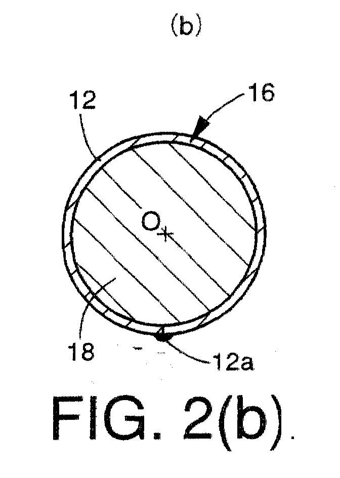
Description
The present invention relates in general to a
hollow structural member of a body structure preferably of a motor
vehicle, and more particularly to such a hollow structural
member provided with an internal reinforcement.
The body structure of a motor vehicle includes
various stationary hollow structural members each of which
includes a hollow body portion such as tubular body portion.
These hollow structural members include impact beams, side
door waists, center pillars and front pillars. The
mechanical strength of each hollow structural member can be
increased by a reinforcement disposed inside the body
portion. For instance, the impact beam disposed within a
side door of a passenger vehicle is provided to minimize
inward deformation of the side door due to an impact load
applied thereto laterally of the vehicle body upon collision
of the vehicle at the side door with a given object.
Generally, the impact beam includes a tubular body portion
having a circular transverse cross sectional shape, and a
pair of fixing portions integrally fixed to the longitudinal
opposite ends of the body portion. The impact beam is
fixedly attached at its fixing portions to the frame of the
side door, such that the body portion of the impact beam
extends in the longitudinal or running direction of the
vehicle. There has been proposed an impact beam of the type
in which a reinforcement is disposed inside a longitudinal
central part of the tubular body portion, in order to
increase the bending strength of the central part so as to
prevent buckling thereof, while minimizing an increase in
the weight of the impact beam. Examples of this type of
impact beam are disclosed in JP-A-4-238727 and JP-6-91325,
which use a tubular reinforcement or a cylindrical solid
reinforcement. The buckling of the impact beam is
interpreted to mean bending of the tubular body portion into
a curved flattened shape due to an impact load laterally
applied thereto. The bending strength is a value of the load
at which the buckling or fracture of the impact beam occurs.
In the conventional tubular structural member as
described above, the bending strength or rigidity
considerably changes at and near the opposite ends of a
reinforcement provided in the tubular body portion, so that
the stress tends to be concentrated around the ends of the
reinforcement, increasing a possibility of cracking or
fracture at the corresponding parts of the tubular body
portion. Thus, the conventional tubular structural member
suffers from a problem of insufficient improvement in the
bending strength.
Explained more specifically referring to Figs. 9
and 10, a test on an impact beam 10' (not provided with a
reinforcement) using a pendulum 30 as shown in Fig. 30
revealed a stress distribution as indicated in the graph of
Fig. 10. In the test, the end face of the pendulum 30 was
forced onto the impact beam 10', at a longitudinal center
point S of the impact beam 10'. A FEM (finite-element
method) analysis showed the stress distribution of Fig. 10
in which the stress continuously decreases in the opposite
longitudinal directions of the impact beam 10', with an
increase in the distance from the point (S) of application
of the load, as indicated at (1) through (4) in Fig. 9. The
stress has a maximum value σmax at the load application
point or center point S. In the graph of Fig. 10, the
distance (mm) from the load application point S is taken
along the abscissa (right and left direction in Fig. 9),
while the value of the stress on the upper side of the
impact beam 10' is taken along the ordinate. It will be
understood from the graph of Fig. 10 that a stress value σ40
at the positions 40mm away from the load application point S
is still considerably large. Accordingly, where a
reinforcement having a length of about 80mm is disposed
within the tubular body portion of the impact beam 10' such
that the opposite ends of the reinforcement are spaced about
40mm away from the load application point S, stress
concentration takes place at or near the opposite ends of
the reinforcement, and the impact beam-10' is likely to be
fractured. It is considered that the use of a reinforcement
having a sufficiently large length is effective to reduce
the stress values around the ends of the reinforcement and
prevent the fracture of the impact beam 10'. However, this
potential solution inevitably results in an undesirable
increase in the weight and material cost of the
reinforcement.
The same is true for a door reinforcement beam disclosed in US Patent 5,255,487, which includes a base tube reinforced by a reinforcing section or a base tube, which is provided with a reinforcement part welded between two ends of the base tube at a position where an impact is expected.
It is therefore an object of the present invention
to provide a hollow structural member for a body structure more particularly of a body structure
of a motor vehicle, which is reinforced with a lightweight,
inexpensive reinforcement which has an effectively improved
bending strength or energy absorption property.
A second object of the invention is to provide
such a reinforcement for use with a hollow structural member
of a body structure, more particularly of a body structure of a motor vehicle.
The first object indicated above may be achieved
according to a first aspect of this invention, which
provides a hollow structural member comprising a hollow body
portion fixedly disposed on a motor vehicle, the hollow
structural member further comprising a reinforcement having
a hollow structure which has an outer surface and which is
fixedly disposed within the hollow body portion having an
inner surface such that the outer surface of the hollow
structure is in substantially close contact with the inner
surface of the hollow body portion, and wherein the
reinforcement includes a longitudinally central portion
having highest bending rigidity, and longitudinally opposite
end portions each having bending rigidity which continuously
decreases in a longitudinal direction from the
longitudinally central portion toward a longitudinal end of
a corresponding one of the longitudinally opposite end
portions, such that the bending rigidity at the longitudinal
end is substantially zero.
The hollow structural member according to the
first aspect of this invention comprises the reinforcement
including the longitudinally central portion having a higher
degree of bending rigidity than the other portion, and the
longitudinally opposite end portions each of which has
bending rigidity that continuously decreases in the
longitudinal direction from the central portion toward the
longitudinal end of the corresponding end portion, such that
the bending rigidity is substantially zero at the
longitudinal end of each end portion. Therefore, the hollow
structural member provides a sufficient degree of buckling
resistance at the central portion of the reinforcement, and
does not suffer from stress concentration around the
opposite ends of the reinforcement, whereby the structural
member used as an impact beam for a side door of the vehicle
has an effectively improved and practically sufficient
bending strength, while minimizing the amounts of increase
in the weight and cost of the structural member due to the
provision of the reinforcement. The reinforcement
constructed as described above has a relatively high degree
of freedom in the choice of its material, and may be
suitably formed of a light metal alloy such as an aluminum
alloy, making it possible to further reduce the weight of
the structural member.
The first object may also be achieved according to
a second aspect of this invention, which provides a hollow
structural member fixedly disposed on a motor vehicle, the
hollow structural member further comprising a reinforcement
having a hollow structure which has an outer surface and
which is fixedly disposed within the hollow body portion
having an inner surface such that the outer surface of the
hollow structure is in substantially close contact with the
inner surface of the hollow body portion, and wherein the
reinforcement includes a thick-walled portion as a
longitudinal central portion thereof, and two
decreasing-thickness portions as longitudinally opposite end
portions thereof disposed on opposite sides of the
thick-walled portion. Each of the two decreasing-thickness
portions has an inner surface which is formed such that a
wall thickness of each decreasing-thickness portion
continuously decreases in a longitudinal direction from the
thick-walled portion toward a longitudinal end of a
corresponding one of the longitudinally opposite end
portions and such that the wall thickness at the
longitudinal end is substantially zero.
The hollow structural member according to the
second aspect of the invention may be considered to be one
form of the hollow structural member according to the first
aspect of the invention. The hollow structure member
according to the second aspect comprises the longitudinally
central thick-walled portion, and the longitudinally
opposite decreasing-thickness end portions each having the
wall thickness which continuously decreases in the
longitudinal direction from the thick-walled central portion
toward the longitudinal end of the corresponding end portion
of the reinforcement, such that the wall thickness is
substantially zero at the longitudinal end of each end
portion of the reinforcement. The present hollow structural
member has substantially the same advantages as described
above with the hollow structural member according to the
first aspect of the invention.
The hollow body portion of the hollow structural
member is preferably a generally tubular member, as
discussed below, but may be a hollow member having a
polygonal shape in transverse cross section. Where the
hollow body portion is a generally tubular member, the
tubular member preferably has a substantially circular
transverse cross sectional shape. However, the tubular body
portion may have an elliptical or oval shape in transverse
cross section. Although the hollow body portion may be a
tube commercially available, it may be formed by bending a
suitable straight metal plate into a tube such that the
opposite edges of the plate are butted together, and then
seam welding the tube along the butted edges, by arc
welding, for example. The metal plate may be a steel plate
whose tensile strength is as high as about 130kgf/mm2. It is
noted that 1kgf/mm2 is approximately equal to 9.8N/mm2.
Where the hollow structural member is an impact
beam installed in a side door of a motor vehicle, for
example, the hollow body portion is generally fixed at its
longitudinal opposite ends to the frame of the side door,
through respective fixing portions, such that the hollow
structural member extends in the longitudinal or running
direction of the vehicle. While the fixing portions may be
separate parts fixed to the opposite ends of the hollow body
portion by welding, for example, the fixing portions may be
integrally formed with the body portion. Where the body
portion is formed from a straight metal plate, for instance,
the fixing portions may be formed by bending appropriate
portions of the plate while the body portion is formed into
a hollow structure. The hollow body portion such as an
impact beam may be formed integrally with the frame or other
part of the vehicle member such as a side door.
The reinforcement disposed within the hollow body
portion may preferably be formed of a metal material such as
a carbon steel (e.g., S45C, JIS) or an aluminum alloy (e.g.,
A5056, JIS). However, the reinforcement may be formed of any
other materials such as FRP (fiber-reinforced plastics) or
other composite material. It is desirable that the
reinforcement be fixedly disposed within a longitudinally
central portion of the hollow body portion (e.g., impact
beam), by suitable means such as press-fitting, bonding with
an adhesive agent, and welding.
In the hollow structural member according to the
second aspect of the invention, the bending rigidity of the
reinforcement is adjusted by suitably changing the wall
thickness of the reinforcement in the longitudinal
direction. According to the first aspect of the invention,
however, the bending rigidity may be adjusted by cutting
slits the reinforcement at its appropriate positions so as
to extend in the longitudinal direction, or by using
different materials at different longitudinal portions of
the reinforcement. For easier installation of the
reinforcement within the hollow body portion, the
reinforcement is preferably formed symmetrically with
respect to the centerline so that the wall thickness at any
longitudinal position is constant around the centerline.
Where an impact load acts on the hollow structural member in
a lateral direction perpendicular to the centerline, for
instance, stress distribution on the structural member is
asymmetric with respect to the centerline, as indicated in
the graph of Fig. 9. In this respect, the reinforcement may
be formed asymmetrically with respect to the centerline, so
as to follow the asymmetric stress distribution. For
instance, the reinforcement may be formed such that the wall
thickness on one side of the centerline remote from the
point of application of the impact load is smaller than that
on the other side, or such that the longitudinal dimension
is shorter on the above-indicated one side. Similarly, the
reinforcement is preferably symmetrical with respect to its
longitudinally central portion (thick-walled portion), but
may be asymmetric with respect to the central portion.
For preventing cracking or fracture of the hollow
structural member due to stress concentration near the ends
of opposite ends of the reinforcement, the wall thickness
value at the opposite ends of the reinforcement is desirably
as small as substantially zero. However, the wall thickness
value at the opposite ends need not be zero, but may be
small enough to prevent the cracking or fracture of the
structural member at the desired maximum load, for example,
2400kgf or 2700kgf, when the structural member is subjected,
at its portion corresponding to the reinforcement, to an
impact load as applied by a testing apparatus as shown n
Fig. 4. Alternatively, the wall thickness values at the
opposite ends of the reinforcement may be suitably
determined depending upon the desired maximum amount of
energy absorption (e.g., about 200kgf·m or about 250kgf·m)
or the desired average load (e.g., about 1200kgf or about
1350kgf). The rate of decrease of the wall thickness and the
longitudinal dimension of each decreasing-thickness end
portion are also desirably determined so as to satisfy the
requirement indicated above, and the wall thickness and the
longitudinal dimension of the thick-walled central portion
are desirably determined so as to prevent buckling of the
structural member under the condition described above.
The wall thickness value at the opposite ends of
the reinforcement for satisfying the above requirement
varies depending upon the bending rigidity (material, wall
thickness and diameter) of the hollow body portion. Where
the reinforcement is formed of a carbon steel (e.g., S45C,
JIS) usually used for a structural member, the wall
thickness at the opposite ends of the reinforcement is
preferably about 0.5mm or smaller, or about 0.3mm or
smaller. Where the reinforcement is formed of an aluminum
alloy (e.g., A5056, JIS), the wall thickness is preferably
about 0.8mm or smaller or about 0.6mm or smaller.
The above-indicated specific values of the desired
maximum load, maximum amount of energy absorption and
average load, and the above-indicated specific values of the
wall thickness at the ends of the reinforcement are provided
for illustrative purpose only, in the case where the hollow
structural member is used as an impact beam for a side door
of a motor vehicle. It is to be understood that the values
of such parameters vary and should be suitably determined,
depending upon the type of the structural member and the
type or model of the motor vehicle.
In a first preferred form of the hollow structural
member according to the second aspect of this invention, the
thick-walled portion consists of at least one solid
partition wall each of which separates a space within the
hollow structure of the reinforcement into two longitudinal
sections. In this case, the hollow structural member has a
sufficient degree of buckling resistance.
In a second preferred form of the hollow
structural member according to the second aspect of the
invention, the hollow body portion has a generally tubular
structure, and the reinforcement has a generally tubular
structure having an outer surface in substantially close
contact with an inner surface of the generally tubular
structure of the hollow body portion. The thick-walled
portion consists of at least one solid partition wall each
of which separates a space within the generally tubular
structure of the reinforcement into two longitudinal
sections, and each decreasing-thickness portion has an
inside diameter which increases in the longitudinal
direction from the thick-walled portion toward the
longitudinal end, so that the wall thickness of each
decreasing-thickness portion linearly decreases in the
longitudinal direction. The solid partition wall permits the
tubular structural member to provide a sufficient degree of
buckling resistance, while the decreasing-thickness portions
whose wall thickness linearly decrease as described above
are relatively easy to manufacture.
In the above preferred form of the hollow
structural member, the inside diameter of each
decreasing-thickness portion increases in the longitudinal
direction from the thick-walled portion toward the
corresponding longitudinal end of the reinforcement, so that
the wall thickness linearly decreases in this longitudinal
direction. However, the wall thickness may be determined so
as to change following the stress distribution on the hollow
structural member upon application of an impact load thereto
in the lateral direction.
In a third preferred form of the hollow structural
member according to the second aspect of the invention, the
thick-walled portion has a wall thickness which non-linearly
changes according to a stress distribution on the hollow
body portion when the the hollow body portion is subject to
an impact load upon collision of the motor vehicle. The
non-linear change of the wall thickness of the thick-walled
portion permits the structural member to have an effectively
improved strength, while minimizing the amounts of increase
in the weight and cost of the structural member due to the
provision of the reinforcement.
In one advantageous arrangement of the second
preferred form of the second aspect of the invention
described above, each solid partition wall has opposite
part-spherical surfaces each of which has a curvature having
a center lying on a centerline of the generally tubular
structure of each reinforcement, and each part-spherical
surface is smoothly contiguous with the inner surfaces of
the two decreasing-thickness portions. In this arrangement,
the hollow structural member has bending rigidity
characteristic similar to a stress distribution (as shown in
Figs. 9 and 10) on the structural member when the hollow
body portion is subjected to an impact load upon collision
of the vehicle. Like the structural member according to the
third preferred form of the invention, the present
structural member has an effectively improved strength, with
minimum amounts of increase in the weight and cost of the
structural member due to the provision of the reinforcement.
This arrangement may be considered as one arrangement of the
third preferred form of the invention described above. It is
also noted that the part-spherical surfaces of the partition
wall whose curvatures lie on the centerline of the
reinforcement are relatively easy to form. In addition, the
smooth connection of the part-spherical surfaces to the
inner surfaces of the decreasing-thickness portions results
in a continuous decrease of the wall thickness of the
reinforcement in the longitudinal direction from the
partition wall to the decreasing-thickness end portions. In
this case, the reinforcement may be easily formed with a
relatively low cost, in a process including a forging step
wherein a blank is forged into a plate from which the
reinforcement is formed.
The stress distribution indicated above, which
changes with the specific types, material, wall thickness,
diameter and length of the hollow structural member, may be
obtained for the specific structural member in question, by
a suitable method such as FEM (finite-element method)
analysis.
In an advantageous arrangement of the first or
second preferred form of the second aspect of the invention,
the reinforcement further includes two constant-thickness
portions formed between the solid partition wall and the two
decreasing-thickness portions, each of the
constant-thickness portion having a constant wall thickness
and cooperating with the solid partifion wall to define
therebetween a fillet having a predetermined radius of
curvature. In this instance, the longitudinal dimension of
each constant-thickness portion is determined depending upon
the longitudinal length of the hollow body portion of the
structural member, which varies with the specific type or
model of the vehicle.
According to one preferred form of the first and
second aspects of the present invention, the reinforcement
is formed as an integral part of the hollow body portion. In
this case, a bonding adhesive such as a resin adhesive is
not necessary for fixing the reinforcement within the hollow
body portion, and the mechanical strength of the structural
member is improved, whereby the weight of the structural
member is reduced. Further, the required number of process
steps for manufacturing the structural member is
significantly reduced, leading to reduced cost of its
manufacture.
Where the hollow body portion of the hollow
structural member is a generally tubular member having a
substantially circular transverse cross sectional shape, for
instance, the structural member may be manufactured in a
process comprising the steps of: (a) rolling a blank into a
plate corresponding to a development of the hollow
structural member in question along a straight line parallel
to the centerline of the structural member, the plate having
a changing-thickness portion corresponding to the
reinforcement portion; (b) forming a plurality or
multiplicity of notches in the surface of the
changing-thickness portion of the plate, which surface has
been shaped by rolling in the above step (a), so that the
plate can be bent into a tube such that the above-indicated
surface having the notches provides an inner surface of the
tube; and (c) bending the notched plate into the tubular
structural member which has a tubular reinforcement as an
integral part of the tubular body portion. However, the
hollow structural member having the integrally formed
reinforcement may be formed in other processes including a
forging step or a machining step.
According to another preferred form of the first
or second aspect of this invention, the reinforcement is
disposed as an intermediate reinforcement in a
longitudinally intermediate portion of the hollow body
portion, and the hollow structural member further comprising
an end reinforcement having a hollow structure having an
outer surface and disposed in at least one of longitudinally
opposite end portions of the hollow body portion, such that
the outer surface of the hollow structure is in
substantially close contact with an inner surface of the
hollow body portion. The end reinforcement includes a
decreasing-thickness portion as one of longitudinally
opposite end portions thereof which is on the side of the
longitudinally intermediate portion of the hollow body
portion. The decreasing-thickness portion has an inner
surface which is formed such that a wall thickness of the
decreasing-thickness portion continuously decreases in a
longitudinal direction from the other of the longitudinally
opposite end portions toward the above-indicated one of the
longitudinally opposite end portions and such that the wall
thickness of the end reinforcement is substantially zero at
a longitudinal end of the above-indicated one end portion of
the decreasing-thickness portion.
In the above form of the hollow structural member,
the end reinforcement disposed in at least one of the
opposite ends of the hollow body portion increases the
buckling resistance and bending strength at a portion of the
structural member at which the structural member is fixed
through an appropriate fixing portion to a frame or other
part of the motor vehicle. This end reinforcement cooperates
with the intermediate reinforcement to further increase the
overall impact resistance and shock absorbing capability of
the hollow structural member. Further, the
decreasing-thickness portion which is provided as a
longitudinally inner end portion of the end reinforcement
has a wall thickness which continuously decreases in the
direction from the outer end toward the inner end of the end
reinforcement such that the wall thickness at the inner end
of the end reinforcement is substantially zero. This
decreasing-thickness portion is effective to prevent stress
concentration and consequent cracking or fracture of the
body portion near the inner end of the end reinforcement.
The end reinforcement may be a hollow member which
is closed by a bottom portion located at the outer end of
the hollow body portion. In this case, the
decreasing-thickness portion is formed adjacent to the
bottom portion such that the wall thickness of the
decreasing-thickness portion continuously decreases in the
longitudinal direction from the closed end (bottom portion)
toward the inner open end of the end reinforcement. The wall
thickness of the bottom portion is suitably determined
depending upon the required strength of the bottom portion.
The bottom portion may have a through-hole, for reducing the
weight of the end reinforcement. It will be understood that
the end reinforcement need not include such a bottom
portion, namely, may be formed so as to have different wall
thickness values at the opposite ends. The end reinforcement
may be provided in only one of the opposite end portions of
the body portion, or alternatively in both of the end
portions of the body portion of the structural member. In
the latter case, the intermediate reinforcement indicated
above is disposed between the two end reinforcements.
The hollow structural member according to the
present invention may be suitably used as an impact beam
fixedly disposed in a side door of the motor vehicle, so as
to extend in a running direction of the vehicle.
Alternatively, the hollow structural member may be used as
any other structural member of the motor vehicle, which may
be selected from among a center pillar, a side door waist, a
side sill, a front pillar, a front cross member, a front
side member and a bumper reinforcing beam of the motor
vehicle. These structural members are given for illustrative
purpose only.
The second object indicated above may be achieved
according to a third aspect of this invention, which
provides a reinforcement fixedly disposed in a hollow
structural member including a hollow body portion fixedly
disposed on a motor vehicle, the reinforcement has a hollow
structure which has an outer surface and which is fixedly
disposed within the hollow body portion such that the outer
surface of the hollow structure is in substantially close
contact with an inner surface of the hollow body portion,
the reinforcement comprises: (a) a longitudinally central
portion having highest bending rigidity; and (b)
longitudinally opposite end portions each having bending
rigidity which continuously decreases in a longitudinal
direction from the longitudinally central portion toward a
longitudinal end of a corresponding one of the
longitudinally opposite end portions, such that the bending
rigidity at the longitudinal end is substantially zero.
The reinforcement according to the third aspect of
the invention has substantially the same advantage as
described above with the hollow structure member according
to the first aspect of the invention.
The second object may also be achieved according
to a fourth aspect of this invention, which provides a
reinforcement fixedly disposed in a hollow structural member
including a hollow body portion fixedly disposed on a motor
vehicle, the reinforcement has a hollow structure which has
an outer surface and which is fixedly disposed within the
hollow body portion such that the outer surface of the
hollow structure is in substantially close contact with an
inner surface of the hollow body portion, the reinforcement
comprises: (a) a thick-walled portion as a longitudinal
central portion thereof; and (b) two decreasing-thickness
portions as longitudinally opposite end portions thereof
disposed on opposite sides of the thick-walled portion, each
of the two decreasing-thickness portions having an inner
surface which is formed such that a wall thickness of each
decreasing-thickness portion continuously decreases in a
longitudinal direction from the thick-walled portion toward
a longitudinal end of a corresponding one of the
longitudinally opposite end portions and such that the wall
thickness at the longitudinal end is substantially zero.
The reinforcement according to the fourth aspect
of the invention has substantially the same advantage as
described above with respect to the hollow structural member
according to the second aspect of the invention.
In one preferred form of the above fourth aspect
of the invention, the reinforcement comprises: (a) a first
piece constituting a first part of the thick-walled portion
and including a first and a second engaging portion at
longitudinally opposite ends thereof; (b) a second piece
including one of the two decreasing-thickness portions and
constituting a second part of the thick-walled portion which
is adjacent to the one of the two decreasing-thickness
portions, the second piece including an engaging end portion
which is remote from the one of the two decreasing-thickness
portions and which engages the second engaging portion of
the first piece; and (c) a third piece including the other
of the two decreasing-thickness portions and constituting a
third part of the thick-walled portion which is adjacent to
the other of the two decreasing-thickness portions, the
third piece including an engaging end portion which is
remote from the other of the two decreasing-thickness
portions and which engages the first engaging portion of the
first piece, the first, second and third parts constituting
the thick-walled portion.
The reinforcement according to the above preferred
form of the fourth aspect of this invention comprises the
three different pieces. The reinforcement may include two or
more first pieces engaging each other such that the first
engaging portion of one of the first pieces engages the
second engaging portion of the adjacent one of the other
first piece or pieces and such that the first and second
engaging portions of the two outer first pieces engage the
third and second pieces, respectively. In this case, the
longitudinal dimension of the thick-walled portion of the
reinforcement can be adjusted by changing the number of the
mutually engaging first pieces. Thus, the present
reinforcement is effective to permit the structural member
to provide an increased bending rigidity over the desired
longitudinal dimension, which changes depending upon the
specific length of the body portion of the structural
member. All of the first, second and third pieces may be
formed of the same material. However, the first, second and
third pieces may be formed of different materials. For
instance, the second and third pieces having the
decreasing-thickness portions which are the opposite end
portions of the reinforcement may be formed of a material
whose rigidity is lower than that of the first piece.
It will be understood that the reinforcement may
consist of one piece, or a plurality of pieces which are
arranged around the centerline of the body portion and
assembled together into a reinforcement. It will also be
understood that a plurality of reinforcements each
consisting of a single piece may be arranged in the
longitudinal direction of the body portion, such that the
reinforcements are disposed adjacent to each other or in
spaced-apart relation with each other.
In another preferred form of the fourth aspect of
this invention, the hollow body portion has a generally
tubular structure and the thick-walled portion consists of a
solid partition wall, as described above with respect to the
second preferred form of the second aspect of the invention,
and each solid partition wall has opposite part-spherical
surfaces each of which has a curvature having a center lying
on a centerline of the generally tubular structure of each
reinforcement and is smoothly contiguous with the two
decreasing-thickness portions. The reinforcement is
manufactured in a process including a forging step of
cold-forging a blank into a plate from which the
reinforcement is formed.
In the above preferred form of the invention
wherein the reinforcement is manufactured in the process
including the cold-forging step, the reinforcement can be
more easily and inexpensively manufactured than where the
reinforcement is manufactured by machining. Further, the
thus manufactured reinforcement has a sufficiently high
mechanical strength with a comparatively small wall
thickness and an accordingly reduced weight. In addition,
the decreasing-thickness portions have continuously
decreasing wall thickness can be comparatively easily formed
by forging a suitable blank such as a cylindrical blank,
with a relatively small number of forging actions, so that
the life of the forging die can be accordingly increased.
However, the reinforcement according to the
present invention may be manufactured in any other process
including a machining step or casting (e.g., aluminum die
casting). Where the reinforcement is manufactured in a
process including a cold-forging step as described above,
the reinforcement is preferably formed of a material which
can easily flow during the forging operation.
The above and optional objects, features,
advantages and technical and industrial significance of this
invention will be better understood by reading the following
detailed description of presently preferred embodiments of
the invention, when considered in connection with the
accompanying drawings, in which:
Referring first to Figs. 1(a), 1(b) and 1(c),
there is shown an impact beam 10 of a side door of a motor
vehicle, which is constructed according to one embodiment of
the present invention. It is noted that the cross sectional
view of Fig. 1(c) is enlarged two times with respect to the
views of Figs. 1(a) and 1(b). The impact beam 10 includes a
tubular body portion 12 having a circular transverse cross
sectional shape as shown in Fig. 1(c), a pair of fixing
portions 14 fixed to the opposite longitudinal ends of the
tubular body portion 12, and a reinforcement 16 fixedly
disposed within a longitudinally central part of the tubular
body portion 12, as indicated in Figs. 1(a) and 1(b).
The impact beam 10 is attached to a frame of the
side door of the vehicle such that the tubular body portion
12 extends in the longitudinal or running direction of the
vehicle, while the upper side of the impact beam 10 as seen
in Fig. 1(b) faces in the laterally outward direction of the
vehicle so that the above-indicated upper side receives a
load upon collision of the vehicle at its side door with a
certain object. The impact beam 10 has an overall length L1
of about 1104mm, and the tubular body portion 12 has a
length L2 of about 950mm. The end portions of the tubular
body portion 12 are inserted into the respective fixing
portions 14 over a length W of about 30mm, and are welded to
the fixing portions 14 over a length of about 25mm, by arc
welding, for example.
The tubular body portion 12 is formed from a
straight rectangular steel plate, for example, a steel plate
SPFC1270Y, JIS (Japanese Industrial Standard) having a
tensile strength of about 130kgf/mm2 and a thickness of
1.6mm. Described more specifically, the steel plate is
formed into a tubular shape having a high degree of
roundness, such that the opposite long-side edges are butted
together. The thus formed tube is welded by arc welding, for
example, at a longitudinally middle section of the tube over
a length of 400mm along the butted edges such that the
welded section 12a extends over 200mm from a longitudinal
center point S of the tube in the opposite longitudinal
directions. The thus obtained tubular body portion 12 has an
outside diameter of about 31.8mm. The tubular body portion
12 is fixed to the fixing portions 14 so that the lower side
of the body portion 12 as seen in Fig. 1(a) faces in the
laterally inward direction of the vehicle.
Each of the fixing portions 14 is formed from a
hot-dip zinc-coated steel plate, for example, steel plate
SGC440, JIS having a tensile strength of 45kgf/mm2 and a
thickness of 1.2mm. Described more particularly, the steel
plate is formed by pressing into the fixing portion 14
having an opening 14a which has a semi-circular bottom whose
radius of curvature is substantially equal to that of the
outer circumferential surface of the tubular body portion
12. That is, the width of the opening 14a as measured in the
direction perpendicular to the thickness direction of the
fixing portion 14 is substantially equal to the outside
diameter of the tubular body portion 12. The opposite end
portions of the tubular body portion 12 are received in the
openings 14a of the fixing portions 14 and secured to the
fixing portions 14 by arc welding, for example. Each fixing
portion 14 has a pair of holes 14b, which are pilot holes
formed through the steel plate and used in a pressing
operation to form the fixing portion 14. These holes 14b are
filled by welding. The length and position of welding of the
welded portion 12a of the tubular body portion 12 may be
changed as needed. The wended portion 12a may be provided
over the entire length of the body portion 12.
Referring next to Figs. 2(a), 2(b) and 2(c), the
reinforcement 16 will be described. The reinforcement 16 is
a tubular member which has a circular transverse cross
sectional shape as indicated in Figs. 2(b) and 2(c), and an
outside diameter substantially equal to the inside diameter
of the tubular body portion 12. The tubular reinforcement 16
is disposed within the tubular body portion 12 such that the
reinforcement is held in close contact at its outer
circumferential surface with the inner circumferential
surface of the body portion 12. The reinforcement 16
includes a thick-walled portion in the form of a solid
partition wall 18 formed in a longitudinally or axially
central portion thereof such that the partition wall 18
extends in the radial direction, so that the interior of the
reinforcement is separated by the partition wall 18 into two
longitudinal sections. The partition wall 18 has a thickness
determined to have give the reinforcement 16 a sufficient
degree of bending strength or rigidity. The thickness is the
dimension in the longitudinal direction of the reinforcement
16.
The reinforcement 16 further includes opposite end
portions in the form of decreasing- thickness portions 20, 20
each formed over a predetermined length E up to the
corresponding outer end such that the two
decreasing- thickness portion 20, 20 are symmetrical with
each other with the partition wall 18 interposed
therebetween in the longitudinal direction of the
reinforcement 16. Each decreasing-thickness portion 20 has a
tapered inner circumferential surface such that the inside
diameter increases in the longitudinal direction from the
partition wall 18 toward the corresponding outer end, so
that the wall thickness of the decreasing-thickness portion
20 linearly decreases in the above-indicated longitudinal
direction until the wall thickness is substantially zeroed
at the outer end so as to form an edge.
The reinforcement 16 also includes two
constant-thickness portions 22 each formed between the
partition wall 18 and the corresponding one of the two
decreasing-thickness portions 20 described above. Each
constant-thickness portion 22 has a constant wall thickness
over its entire length in the longitudinal direction of the
reinforcement 16. The rate of change or decrease of the wall
thickness (taper angle) and the length E of the
decreasing-thickness portions 20, and the wall thickness at
the outer ends of these portions 20 are determined so that
the bending rigidity of the reinforcement 16 smoothly
decreases in the longitudinally outward directions and is
almost zeroed at the outer ends (edges), in order to avoid
cracking or fracture of the tubular body portion 12 due to
stress concentration at the end portions of the
reinforcement 16. Between the partition wall 18 and the
constant-thickness portions 22, there are formed annular
fillets 23 having a suitable radius of curvature, in order
to avoid sudden changes of the bending rigidity of the
reinforcement 16 and consequent stress concentration at the
parts between the partition wall 18 and the
constant-thickness portions 22.
The reinforcement 16 is symmetrical with respect to its
centerline O in all radial directions. Namely, the wall
thickness of the reinforcement 16 at any longitudinal
position thereof is constant in the circumferential
direction. Therefore, the reinforcement 16 can be disposed
within the tubular body portion 12, without specific
positioning of the reinforcement 16 relative to the tubular
body portion 12 in the circumferential direction. The wall
thickness values of the portions 18, 20, 22 and the radius
of curvature of the fillets 23 may be determined as needed
depending upon the material of the reinforcement 16. In the
present specific embodiment, the reinforcement 16 is formed
of a carbon steel (used for structural members), for
example, SC45, JIS, and has the dimensions (in mm) as
indicated in Fig. 3 and a weight W of about 122gf. The
reinforcement 16 may be formed by cold forging or machining.
In the present embodiment, the reinforcement 16 is formed by
machining, and press-fitted into the tubular body portion 12
through one of the opposite open ends of the body portion 12
before the fixing portions 14 are welded to the body portion
12. When the reinforcement 16 is press-fitted in the tubular
body portion 12, the reinforcement 16 is positioned in the
longitudinal direction relative to the body portion 12, by a
suitable positioning jig inserted into the body portion 12
through the other open end of the body portion 12, such that
the longitudinal center point (partition wall 18) of the
reinforcement 16 is substantially aligned with or located at
the longitudinal center point S of the body portion 12, as
indicated in Fig. 2(a). In the present embodiment, the
reinforcement 16 is fixed in the body portion 12 by means of
only an interference fit therebetween. However, the
reinforcement 16 may be fixed to the body portion 16 by
other means such as welding or a bonding agent such as a
resin material.
As described above, the the impact beam 10
according to the present embodiment is reinforced by the
reinforcement 16 which has the partition wall 18 at its
longitudinally central portion, and the decreasing-thickness
portions 20 as the longitudinally opposite end portions each
formed over the length E such that the wall thickness of
each decreasing-thickness portion 20 linearly decreases in
the longitudinally outward direction toward the end so that
the thickness at the end is almost zero. The reinforcement
16 is fixed at the longitudinally central portion of the
tubular body portion 12, so that the impact beam 10 has a
sufficiently high buckling resistance around the
longitudinal center point S of the body portion 12, and does
not suffer from stress concentration around the ends of the
reinforcement 16. Thus, the bending strength of the impact
beam 10 is effectively increased to a practically
satisfactory value, without considerable amounts of increase
in the weight and cost of manufacture of the impact beam 10
due to the provision of the reinforcement 16.
Further, the thick-walled portion in the form of
the partition wall 18 gives the reinforcement 16 a
significantly increased resistance to buckling, while the
decreasing-thickness portions 20 whose wall thickness value
linearly decreases can be comparatively easily and
economically formed. In addition, the constant-thickness
portions 22 having a constant wall thickness and formed
between the partition wall 18 and the decreasing-thickness
portions 20 so as to define the fillets 23 therebetween with
a suitable radius of curvature make it possible to give the
reinforcement 16 a desired bending rigidity, depending upon
the length dimension of the constant-thickness portions 22.
Accordingly, by suitably determining the length dimension of
the constant-thickness portions 22, the reinforcement 16 can
be used for various impact beams 10 whose tubular body
portions 12 have different length dimensions.
To further clarify the advantage of the present
embodiment, a bending test was conducted on the impact beam
10, using a testing apparatus as shown in Fig. 4. To conduct
the bending test, the impact beam 10 was set on the testing
apparatus, by first securing the two fixing portions 14 to
respective metal support members 24 by arc welding, and then
fastening the support members 24 to a surface plate 26 of
the testing apparatus by bolts 29. The two support members
24, each of which has a U shape in cross section, were
positioned on the surface plate 26 such that the U-shaped
openings of the support members 23 are open toward each
other. The support members 24 are reinforced by respective
reinforcing plates 28 secured thereto by arc welding, so as
to provide highly rigid support structures 24, 28 which
undergo substantially no deformation in the bending test.
The impact beam 10 was positioned so as to have a
substantially horizontal attitude, such that the welded
portion 12a of the body portion 12 which is to face in the
laterally inward direction of the vehicle when installed on
the vehicle is located on the lower side of the impact beam
10 or faces downward.
In this condition, the pendulum 30 having a
semi-circular cross sectional shape as shown in Fig. 4 was
lowered substantially in the vertical direction, onto to the
tubular body portion 12 at the longitudinal center point S
of the latter. The pendulum 30 has a radius of curvature of
152mm and a thickness of 40mm. The amount of downward
displacement of the body portion 12 at the center point S
(namely, the amount of downward movement of the pendulum 30)
was measured at different values of the load which acts on
the body portion 12 through the pendulum 30.
The graph of Fig. 5 indicates a relationship
between the amount of displacement and the load. The
pendulum 30 was lowered over its maximum operating stroke of
202.3mm, that is, lowered to its lower stroke end, without
fracture or buckling of the impact beam 10. The maximum load
measured at the lower stroke end of the pendulum 30 was
3367kgf. As indicated in row No. 1 of the table of Fig. 24,
the amount of energy absorption by the impact beam 10 by the
time the pendulum 30 was lowered to its lower stroke end was
318.7kgf·m, and the average load was 1576.9kgf. The energy
absorption amount is an integral of the load values by the
time the pendulum 30 was lowered to a given point (to the
lower stroke end in the above case), and the average load is
obtained by dividing the energy absorption amount by the
displacement. The row No. 1 of the table of Fig. 24 also
indicates the energy absorption amount and the average load
when the displacement was 152mm (6 inches). Broken line in
the graph of Fig. 5 indicates this displacement value of
152mm.
There will be described various other embodiments
of this invention, wherein the same reference numerals as
used in the first embodiment will be used to identify the
functionally corresponding elements, and redundant
descriptions of those elements will not be provided.
Referring to the partly cut-away view of Fig. 6,
there is shown an impact beam 32 for a side door of a motor
vehicle, which is constructed according to a second
embodiment of this invention. The impact beam 32 is
substantially identical in construction with the impact beam
10 of Figs. 1(a)-1(c), except for the provision of an end
reinforcement 34 disposed in each of the opposite axial end
portions of the tubular body portion 12, in addition to the
intermediate reinforcement 16.
The end reinforcement 34 is shown in enlargement
in Figs. 7(a), 7(b) and 7(c). This end reinforcement 34 is a
tubular member which has an outside diameter substantially
equal to the inside diameter of the tubular body portion 12.
The end reinforcement 34 is disposed such that its outer
circumferential surface is held in substantially close
contact with the inner circumferential surface of the
tubular body portion 12. The tubular member of the end
reinforcement 34 is closed by a bottom portion 36 at one
axial end thereof, which closes the corresponding end of the
tubular body portion 12. The bottom portion 36 has a wall
thickness determined to have a desired bending rigidity or
strength. The end reinforcement 34 further has a
decreasing-thickness portion 38 whose inner circumferential
surface is tapered such that the wall thickness linearly
decreases in the axial direction from the bottom portion 36
at the above-indicated one axial end toward the other open
inner axial end, namely, toward the axially central portion
of the body portion 12. The thickness of the
decreasing-thickness portion 38 is substantially zero at the
inner axial end. The rate of decrease of the wall thickness
(taper angle) of the decreasing-thickness portion 38 and the
thickness at the inner axial end of the portion 38 are
determined so that the bending rigidity or strength smoothly
decreases in the above-indicated axial direction such that
the bending rigidity at the inner axial end of the portion
38 is substantially zero, in order to prevent cracking or
fracture of the tubular body portion 12 due to stress
concentration around the inner axial end of the portion 38.
The end reinforcement 34 is secured within the body portion
12 by suitable means such as a bonding adhesive such that
the outer end surface of the bottom portion 36 is
substantially flush with the corresponding end face of the
body portion 12. The axial dimension of the end
reinforcement 34 is determined so that its inner end is
spaced from the inner end of the corresponding fixing
portion 14 by a suitable distance in the axial direction
toward the central portion of the body portion 12. The end
reinforcement 34 is formed of a material similar to that of
the reinforcement 16. For instance, the end reinforcement 34
is formed of a carbon steel generally used for structural
members.
The impact beam 32 according to the present second
embodiment of the invention has the advantage described
above with respect to the first embodiment. Further, the
present impact beam 32 including the end reinforcements 34
disposed within the opposite end portions of the body
portion 12 has an additional advantage in the buckling
resistance and bending strength at the opposite end portions
of the tubular body portion 12 at which the body portion 12
is fixed to the fixing portions 14 through which the load is
received by the frame member of the side door. As explained
above, each end reinforcement 34 is a tubular member
including the bottom portion 36 at its one axial end and the
decreasing-thickness portion 38 whose wall thickness
linearly decreases in the axial direction from the bottom
portion 36 toward the other or inner axial end such that the
wall thickness at the inner axial end is substantially zero.
This end reinforcements 34 cooperate with the central
reinforcement 16 for reinforcing the central portion of the
body portion 12 to improve the overall impact resistance and
impact energy absorption characteristic. In addition, the
continuous reduction of the wall thickness of the end
reinforcement 34 to a substantially zero value at the inner
end of the end reinforcement 34 is effective to prevent the
stress concentration around the inner end of the end
reinforcement 34, thereby minimizing the possibility of
cracking and fracture of the body portion 12 near the inner
end of the end reinforcement.34.
Referring to Fig. 8, there is shown a
reinforcement 40 constructed according to a third embodiment
of this invention. The reinforcement 40 includes a
thick-walled portion in the form of a solid partition wall
42, and two decreasing-thickness portions 44 on the opposite
sides of the partition wall 42. The wall thickness of the
partition wall 42 changes non-linearly following a pattern
of stress distribution when the impact beam is subject to a
load. Described in detail, each of the opposite surfaces of
the partition wall 42 is a part-spherical surface having a
suitable curvature with its center being located on the
centerline O of the tubular reinforcement 40. The thickness
of the partition wall 42 is minimum on the centerline O and
non-linearly increases in the radially outward direction so
that the partition wall 42 is smoothly contiguous, at its
radially outer end, with the large-thickness ends of the
decreasing-thickness portions 44 whose wall thickness
linearly changes with its inside diameter linearly
increasing in the opposite longitudinal directions from the
partition wall 42 toward the ends of the reinforcement 40.
The reinforcement 40 is symmetrical with respect to the
centerline O and with respect to the partition wall 42.
Fig. 9 shows a stress distribution on an impact
beam 10' which consists of the tubular body portion 12 and
the fixing portions 14 but does not include any
reinforcement. This stress distribution was obtained by a
FEM (finite-element method) analysis when the end face of
the pendulum 30 was forced onto the impact beam 10', at the
longitudinal center point S, as in the bending test of Fig.
4. In this stress distribution, the stress continuously
decreases in the opposite longitudinal directions of the
impact beam 10', with an increase in the distance from the
load application point (S), as indicated at (1) through (4)
in Fig. 9. The stress has a maximum value σmax at the load
application point or center point S, as indicated in the
graph of Fig. 10. In this graph, the distance (mm) from the
load application point S is taken along the abscissa (right
and left direction in Fig. 9), while the value of the stress
on the upper side of the impact beam 10' is taken along the
ordinate. It will be understood from the graph of Fig. 10
that the stress non-linearly changes with the distance from
the load application point S. The radius of curvature of the
opposite part-spherical surfaces of the partition wall 42 of
the reinforcement 40 is determined so that the bending
strength or rigidity of the impact beam provided with the
reinforcement 40 follows the stress distribution of Fig. 10
as much as practical.
The reinforcement 40 is formed of an aluminum
alloy, more specifically, an aluminum alloy A5056, JIS, and
has dimensions (mm) as indicated in Fig. 8 and a weight W of
about 63gf. Like the reinforcement 16 of Fig. 2(a), the
reinforcement 40 is formed by machining and fixed by press
fitting within the tubular body portion 12, at the
longitudinal center point S of the body portion 12.
Like the reinforcement 16 used in the first and
second embodiments of Figs. 2 and 6, the reinforcement 40
according to the third embodiment of Fig. 8 gives an
increased buckling resistance around the longitudinal center
point S of the body portion 12 of the impact beam, while
preventing stress concentration near the opposite ends of
the reinforcement 40, so that the bending strength of the
impact beam is effectively improved to a practically
satisfactory level, while minimizing the amounts of increase
in the weight and cost of manufacture of the impact beam due
to the use of the reinforcement 40. In particular, the use
of an aluminum alloy considerably reduces the weight of the
reinforcement 40, that is, to about a half that of the
reinforcement 16 formed of a carbon steel. Further, the
thick-walled portion in the form of the partition wall 42
whose wall thickness non-linearly changes provides an
increased buckling resistance, while the
decreasing-thickness portions 44 whose wall thickness
linearly changes provides are comparatively easy to
manufacture, like the decreasing thickness portions 20, 38.
Since the opposite part-spherical surfaces of the
partition wall 42 are smoothly contiguous with the inner
surfaces of the decreasing-thickness portions 44, the
reinforcement 40 has a bending rigidity distribution similar
to the stress distribution indicated in Fig. 10, so that the
bending strength is most effectively increased while
minimizing the amounts of increase in the weight and cost of
the impact beam. In addition, the center of the curvature of
each part-spherical surface of the partition wall 42 lies on
the centerline O of the reinforcement 40, the partition wall
42 is comparatively easy to manufacture.
A bending test was conducted on the impact beam in
which the reinforcement 40 rather than the reinforcement 16
is press-fitted in the tubular body portion 12. The test was
conducted in the same manner used in the bending test of
Fig. 4. The test of this impact beam showed a
load-displacement relationship as indicated in the graph of
Fig. 11. In this test in which the holes 14b in the fixing
portions 14 were not filled, the fixing portions 14 were
fractured at the open holes 14b when the displacement
increased to 185.4mm with the application of a load of
2944kgf. As indicated in row No. 2 of the table of Fig. 24,
the amount of energy absorption by the impact beam at the
maximum load (maximum displacement of 2944kgf) was
265.3kgf·m, and the average load was 1431.0kgf. The maximum
load values in Fig. 24 corresponds to the bending strength.
Although the reinforcement 40 of Fig. 8 is formed
by machining, it may be formed by cold forging as shown in
Figs. 12(a) and 12(b). The cold forging is effected by using
a forging die 46 which has a forming hole 48 having an
inside diameter substantially equal to the outside diameter
of the reinforcement 40. The forging die 46 is adapted to
receive a knock-out 52 and a punch 56 in a bottom portion of
the forming hole 48, as indicated in Fig. 12(a). The
knock-out 52 has an outer forming surface 50 which is formed
so as to follow the part-spherical surface of the partition
wall 42 and the inner circumferential surface of the
decreasing-thickness portion 44. The knock-out 52 is
vertically movable in the forming hole 48. The forging die
46 is further adapted to receive a punch 56 in an upper
portion of the forming hole 48. The punch 56 has a forming
surface 54 identical with the forming surface 50 of the
knock-out 52, as indicated in Fig. 12(b). In a forging
operation, the punch 56 is lowered into the forming force
48, to a predetermined lower stroke end thereof toward the
knock-out 52 held in a predetermined position.
To form the reinforcement 40 by cold forging, a
solid cylindrical blank 58 of aluminum alloy A5056, JIS
whose outside diameter and volume (mass) are substantially
equal to those of the reinforcement 40 is inserted into the
forming hole 48 of the forging die 46, while the punch 56 is
located at a fully retracted position above the die 46 and
the knock-out 52 is located at the predetermined position,
as indicated in Fig. 12(a). The blank 58 is subjected to a
bonderizing or other treatment as needed, before the forging
operation. In the state of Fig. 12(a), the punch 56 is
lowered to its lower stroke end within the forging hole 48,
with the forming surface 54 facing the blank 58, so that the
blank 58 is forged between the forming surfaces 50, 54 of
the knock-out 52 and punch 56, as indicated in Fig. 12(b),
whereby the reinforcement 40 is formed. Then, the knock-out
52 is moved upward, forcing the formed reinforcement 40 out
of the forming hole 48. While the blank 58 may be forged
into the reinforcement 40 by a single forging action, two or
more forging actions may be performed to forge the blank 58
into the reinforcement 40. If necessary or desired, the
reinforcement as forged may be subjected to a finish
machining operation.
The cold forging operation to manufacture the
reinforcement 40 is easier and less costly than a machining
operation, and ensures a higher mechanical strength, making
it possible to reduce the required wall thickness of the
reinforcement 40, thereby resulting in a reduced weight of
the reinforcement 40. Further, since the reinforcement 40 is
shaped with its wall thickness continuously decreasing in
the opposite axial directions from the partition wall 42
toward the opposite ends of the reinforcement 40, the
forging operation can be easily achieved with relatively
small loads acting on the forging die 46, punch 56, etc.
This leads to a prolonged life of the forging die 46, and a
reduced number of forging actions required for forging the
cylindrical blank 58 into the reinforcement 40. The forging
operation is further facilitated by the use of an aluminum
alloy material which flows relatively easily during the
forging operation.
Referring to Fig. 13, there is shown an impact
beam 160 for a side door of a motor vehicle, in cross
section taken in a plane including the centerline O of the
impact beam 160. This impact beam 160, which is constructed
according to a fourth embodiment of the invention, is a
generally tubular member including a reinforcement portion
162 integrally formed as a longitudinally central portion
thereof. The reinforcement portion 162 has an annular
projection 164 formed on the inner circumferential surface,
at a longitudinally central part thereof. This annular
projection 164 has a semi-circular shape in cross section as
shown in Fig. 13. The reinforcement portion 162 further has
two decreasing- thickness portions 166, 166 on the opposite
sides of the annular projection 164. The inner
circumferential surface of each decreasing-thickness portion
166 is tapered such that the wall thickness of the
decreasing-thickness portion 166 is maximum at one end
thereof adjacent to the annular projection 164 and linearly
decreases in the axial direction from the above-indicated
one end to the other end. In this embodiment, the
reinforcement portion 162 has a length of about 150mm, and
the impact beam 160 has an outside diameter of about 31.8mm.
The wall thickness of the impact beam 160 at its portions
other than the reinforcement portion 162 is about 1.6mm. The
wall thickness of the reinforcement portion 162 at the axial
center of the annular projection 164 is about 7.0mm. That
is, the radial dimension from the outer circumferential
surface of the impact beam 160 to the tip of the annular
projection 164 is about 7.0mm. The annular projection 164
has a radius of curvature of about 4mm. Like the tubular
body portion 12 of the impact beam 10, the impact beam 160
is formed from a steel plate having a high tensile strength.
An example of a process of manufacturing the
impact beam 160 will be described by reference to the flow
chart of Fig. 14. The process is initiated with step 1 in
which a blank is hot-rolled by a roller rolling 170, into a
plate 182 which corresponds to a plurality of developments
of the impact beam 160 along a straight line parallel to the
axis or centerline O. As shown in Fig. 15, the plate 182 has
a changing-thickness portion 180 corresponding to the
reinforcement portion 162. The changing-thickness portion
180 has the same thickness variation as the wall thickness
variation of the reinforcement portion 162. The roller 170
has an annular groove 172 formed in a longitudinal central
part thereof, and a pair of tapered portions 174 formed on
the opposite sides of the annular groove 172. The annular
groove 172 has a semi-circular shape in cross section, and
each tapered portion 174 has an outside diameter which
continuously increases in the axial direction from the
annular groove 172 toward its end remote from the annular
groove 172.
In the next step 2, a plurality of parallel
notches 168 are formed, as shown in Fig. 16, in the surface
of the changing-thickness portion 180 of the plate 182,
which surface was shaped by the roller 170 in the roller
step 1. The notches 168 are formed at a predetermined
interval in the changing-thickness portion 180, by a
notching roller having a plurality of blades or teeth for
forming the notches 168. The blades or teeth are formed so
as to extend in the axial direction of the notching roller,
and the notching roller is disposed downstream of the
rolling roller 170 such that the axes of the rolling and
notching rollers are parallel to each other. With these
rollers rotated synchronously with each other, the notching
step 2 to form the notches 168 in the changing-thickness
portion 180 of the plate 182 is performed following the
rolling step 1 in which the plate 182 is formed by the
roller roller 170. The notches 168 may be formed after the
plate 182 is cut in the following step 3 into elongate
strips 182a. In this case, the notches 168 may be formed in
each strip 182a by a rotary cutter, for example.
In the step 3, the plate 182 in which the notches
168 have been formed in the step 2 is cut by a suitable
cutter, along parallel cutting lines at a predetermined
interval, for example, at an interval of 99.8mm, as
indicated in Fig. 16. Thus, the plate 182 is cut into a
plurality of elongate strips 182a, one of which is shown in
Figs. 17(a), 17(b) and 17(c) taken long line 17(c)-17(c) of
Fig. 17(a), the notches 168 are grooves which have a V shape
in cross section. The angle of the V-grooves 168 is
determined so that the opposed surfaces of each V-groove 168
come into contact with each other when the elongate strip
182a is formed into a tube in the following step 4.
In the step 4, each elongate strip 182a is first
subjected to a bending operation on a press so that the
strip 182a is formed into a U-shaped structure. Then, the
U-shaped structure is subjected to a bending operation so
that the U-shaped structure is formed into a tube wherein
the opposite long-side edges of the strip 182a are butted
together, while the opposite surfaces of each V-grooves
notch 168 contact each other. Then, step 5 is implemented to
effect seam welding along the butted edges of the tube. This
seam welding may be effected by arc welding, for example.
Thus, the impact beam 160 having the integrally formed
reinforcement 162 at its longitudinally central portion is
manufactured. The impact beam 160 may be subjected to a
suitable heat treatment such as hardening or annealing.
The impact beam 160 having the integral
reinforcement portion 162 does not require a bonding
adhesive such as a resin material for fixing the
reinforcement portion 162, and accordingly has an increased
mechanical strength and a reduced weight. Further, the
number of the required process steps is significantly
reduced and the cost of manufacture of the impact beam 160
is accordingly reduced.
Referring to Fig. 18, there will be described a
reinforcement 60 according to a fifth embodiment of this
invention. Like the reinforcement 16 of the first
embodiment, the reinforcement 60 consists of a thick-walled
portion in the form of a solid partition wall 62, two
constant-thickness portions 64 and two decreasing-thickness
portions 66. The reinforcement 60 is formed of an aluminum
alloy, that is, more specifically, alloy A5056, JIS, and has
dimensions (mm) as indicated in Fig. 18. The reinforcement
60 has a weight W of about 40gf. Like the reinforcement 16,
the reinforcement 60 is formed by machining, and is
press-fitted within the tubular body portion 12, at the
longitudinally center point S. The reinforcement 60 is
symmetrical with respect to the centerline O and with
respect to the partition wall 62.
The reinforcement 60 of this fifth embodiment has
substantially the same advantage as the reinforcement 16 of
the first embodiment. In addition, the reinforcement 60
formed of an aluminum alloy such that the wall thickness
values of the portions 62, 64, 66 are reduced to the minimum
values required to assure the desired bending strength, so
that the impact beam 60 has the weight W as small as about
40gf.
A bending test was conducted on the impact beam in
which the reinforcement 60 rather than-the reinforcement 16
is press-fitted in the tubular body portion 12. The test was
conducted on the testing apparatus of Fig. 4. The test of
this impact beam showed a load-displacement relationship as
indicated in the graph of Fig. 19. In this test, the support
members 24 of the testing apparatus were fixed by the bolts
29 to the surface plate 26 such that the U-shaped openings
of the support members 24 were open outwardly of the
apparatus. The support members 24 were fractured at their
portions welded to the reinforcing plates 28, when the
displacement increased to 196.7mm with the application of a
load of 2833kgf. As indicated in row No. 3 of the table of
Fig. 24, the amount of energy absorption by the impact beam
at the maximum load (maximum displacement of 2833kgf) was
276.5kgf·m, and the average load was 1405.7.0kgf. The length
of the welded sections 12a of the body portion 12 was 500mm.
Reference is now made to Figs. 20 and 21 showing
comparative reinforcements 70 and 72. The reinforcement 70
shown in Fig. 20 is a solid cylindrical member, while the
reinforcement 72 shown in Fig. 21 is a tubular member. The
reinforcements 70, 72 are both formed of carbon steel S45C,
JIS, and have the dimensions as indicated in Figs. 20 and
21, so that these two reinforcements 70, 72 have
substantially the same weight W as the reinforcement 16.
Bending tests were also conducted on the impact
beams in which the reinforcements 70, 72 rather than the
reinforcement 16 were press-fitted in the tubular body
portion 12. The tests were conducted in the same manner as
in the test of Fig. 4. The tests showed load-displacement
relationships as indicated in the graphs of Figs. 22 and 23,
respectively. The two impact beams were both fractured due
to stress concentration near the ends of the reinforcement
70, 72. The reinforcement 70 had a maximum displacement of
143.0mm and a maximum load of 1958kgf, while the
reinforcement 72 had a maximum displacement of 121.9mm and a
maximum load of 1876kgf. As indicated in rows Nos. 4 and 5
of the table of Fig. 24, the amounts of energy absorption by
the impact beams at the maximum load were 131.9kgf·m
(reinforcement 70) and 112.3kgf·m (reinforcement 72), and
the average load values were 922.3kgf (reinforcement 70) and
921.2kgf (reinforcement 72).
It will be understood that the maximum load value
of the impact beam provided with the reinforcement 16
(indicated in the row No. 1 of Fig. 24) is about 1.7-1.8
times those of the impact beams provided with the
reinforcements 70, 72, and that the energy absorption
amounts of the former is about 2.4-2.8 times those of the
latter. In this respect, it is noted that the reinforcement
16 is formed of the same material as the reinforcements 70,
72. It will also be understood that the maximum load values
and the energy absorption amounts of the impact beams
provided with the reinforcement 40 (indicated in the row No.
2) and the reinforcement 60 (indicated in the row No. 3) are
considerably improved over those of the impact beams
provided with the comparative reinforcements 70, 72.
Referring to Fig. 25, there is shown a
reinforcement 80 constructed according to a sixth embodiment
of this invention, which consists of a first piece 82, a
second piece 84, a third piece 86, and two auxiliary pieces
88 disposed at mutually engaging end portions of the three
pieces 82, 84, 86. As shown in Figs. 26(a), 26(b) and 26(c),
the first piece 82 is a tubular member having an outside
diameter substantially equal to the inside diameter of the
tubular body portion 12. This tubular member includes a
partition wall 90 at an axially central portion thereof, and
a first engaging portion 92 at one of opposite axial ends
thereof and a second engaging portion 92 at the other axial
end. The first engaging portion 92 has an inside diameter
substantially equal to an outside diameter of the second
engaging portion 94. The partition wall 90 has opposite
part-spherical surfaces each of which has a suitable
curvature having a center lying on the centerline O of the
first piece 80. The inner circumferential surfaces between
the partition wall 90 and the first and second engaging
portions 92, 94 are tapered such that the wall thickness
continuously decreases in the opposite axial directions from
the partition wall 90 toward the engaging portions 92, 94.
Each of the engaging portions 92, 94 has an axial length of
about 10mm and a wall thickness of about 2mm. The first
piece 82 has an overall axial length of about 120mm
(including the lengths of the engaging portions 92, 94). The
radius of curvature of each part-spherical surface of the
partition wall 90 is about 8mm. Fig. 26(a) is a longitudinal
or axial cross sectional view taken in a plane including the
centerline O, while Figs. 26(b) and 26(c) are end
elevational views taken in the opposite axial directions
toward the first and second engaging portions 92, 94,
respectively. While the portions between the partition wall
90 and the engaging portions 92, 94 are decreasing-thickness
portions with the tapered inner circumferential surfaces,
they may be constant-thickness portions having constant
inner and outer diameters.
As shown in Fig. 27, the second piece 84 is also a
tubular member having an outside diameter substantially
equal to the inside diameter of the body portion 12. This
tubular member includes a partition wall 96 at an axially
central portion thereof, and a decreasing-thickness portion
98 on one side of the partition wall 96. The
decreasing-thickness portion 98 has a tapered inner
circumferential surface such that the wall thickness
linearly decreases in the axial direction from the partition
wall 96 toward one end of the second piece 84, at which the
wall thickness is substantially zero. The partition wall 96
has opposite part-spherical surfaces each of which has a
curvature having a center lying on the centerline O. One of
these part-spherical surfaces is smoothly contiguous with
the inner surface of the decreasing-thickness portion 98.
The axial portion of the second piece 84 on the other side
of the partition wall 96 - (remote-from the
decreasing-thickness portion 98) is identical in size and
shape with the axial portion of the first piece 82 which
includes the first engaging portion 92. This axial portion
of the second piece 84 includes an engaging portion 100
identical with the first engaging portion 92. The engaging
portion 100 is engageable with the second engaging portion
94 of the first piece 82 such that the inner circumferential
surface of the engaging portion 100 is in substantially
close contact with the outer circumferential surface of the
engaging portion 94.
As shown in Fig. 28, the third piece 86 is also a
tubular member paving an outside diameter substantially
equal to the inside diameter of the body portion 12. This
tubular member includes a partition wall 102 at an axially
central portion thereof, and a decreasing-thickness portion
104 on one side of the partition wall 102. The
decreasing-thickness portion 104 has a tapered inner
circumferential surface such that the wall thickness
linearly decreases in the axial direction from the partition
wall 96 toward one end of the third piece 86, at which the
wall thickness is substantially zero. The partition wall 102
has opposite part-spherical surfaces each of which has a
curvature having a center lying on the centerline O. One of
these part-spherical surfaces is smoothly contiguous with
the inner surface of the decreasing-thickness portion 104.
The axial portion of the third piece 84 on the other side of
the partition wall 96 (remote from the decreasing-thickness
portion 104) is identical in size and shape with the axial
portion of the first piece 82 which includes the second
engaging portion 94. This axial portion of the third piece
86 includes an engaging portion 106 identical with the
second engaging portion 94. The engaging portion 106 is
engageable with the first engaging portion 92 of the first
piece 82 such that the outer circumferential surface of the
engaging portion 106 is in substantially close contact with
the inner circumferential surface of the engaging portion
92.
Each of the two auxiliary pieces 88 is a solid
disk-shaped member having a circular cross sectional shape,
as shown in Figs. 29(a) and 29(b). These auxiliary pieces 88
are engageable with the inner surfaces of the second
engaging portion 94 of the first piece 82 and the engaging
portion 106 of the third piece 86, respectively.
The first, second and third pieces 82, 84, 86 and
the auxiliary pieces 88 are all formed of an aluminum alloy,
more specifically, an aluminum alloy A5056, JIS, by cold
forging or machining. When the reinforcement 80 is assembled
in the tubular body portion 12, the third piece 86 is
initially forced into the body portion 12 with the
decreasing-thickness portion 104 leading the other portions,
until the engaging portion 106 is located close to the
appropriate open end of the body portion 12. Then, one of
the auxiliary pieces 88 is brought into engagement with the
inner circumferential surface of the engaging portion 106 of
the third piece 86, and the first engaging portion 92 of the
first piece 82 is brought into engagement with the outer
circumferential surface of the engaging portion 106. The
first piece 82 is forced into the body portion 12, together
with the third piece 86, until the second engaging portion
92 of the first piece 82 is located close to the open end of
the body portion 12. Then, the other auxiliary piece 88 is
brought into engagement with the inner circumferential
surface of the second engaging portion 94 of the first piece
82, and the engaging portion 100 of the second piece 84 is
brought into engagement with the outer circumferential
surface of the second engaging portion 94 of the first piece
82. Finally, the second piece 84 is forced into the body
portion 12, together with the first and third pieces 82, 86,
until the reinforcement 80 consisting of the pieces 82,84,
86, 88 is located at a predetermined axial position of the
body portion 12.
Where the side door has a relatively large size
and the body portion 12 of the impact beam is accordingly
long, the reinforcement 80 may include two more more first
pieces 82 connected to each other at the first and second
engaging portions 92, 94.
In the reinforcement 80 assembled as shown in Fig.
25, the axial portion between the partition wall 96 of the
second piece 84 and the partition wall 102 of the third
piece 86 functions as a long thick-walled portion having a
relatively high bucking resistance, and the
decreasing- thickness portions 98, 104 at the opposite end
portions of the reinforcement 80, which portions 98, 104 are
effective to prevent stress concentration near the opposite
axial ends of the reinforcement 80. Thus, the bending
strength of the impact beam is effectively increased by the
reinforcement 80. Further, a desired number of first pieces
82 can be connected to each other, so that bending strength
of the impact beam can be improved over a desired length. In
other words, the length of the reinforcement 80 can be
adjusted by changing the number of the first pieces 82,
depending upon the length of the tubular body portion 12 of
the impact beam, which changes with the specific types or
models of the vehicle.
A reinforcement 110 constructed according to a
seventh embodiment of the invention is shown in Fig. 30.
This reinforcement 110, which is basically similar in shape
to the reinforcement 40, includes a thick-walled portion in
the form of a partition wall 112, and decreasing- thickness
portions 114, 114. However, the reinforcement 110 is
asymmetric with respect to the centerline O. Namely, the
reinforcement 110 has a shorter axial dimension at a lower
part as seen in Fig. 30, in view of the stress distribution
indicated in Fig. 9. The lower part of the reinforcement 110
is located on the laterally inner side of the vehicle when
the impact beam provided with the reinforcement 110 is
installed in the side door of the vehicle. Thus, the
reinforcement 110 has a reduced weight, while assuring a
sufficiently high bending strength with respect to a load
which acts on the reinforcement 110 in the downward
direction as seen in Fig. 30, that is, in the laterally
inward direction of the vehicle.
A reinforcement 120 according to an eighth
embodiment of the invention is shown in. Fig. 31. This
reinforcement 40, which is also basically similar in shape
to the reinforcement 40, includes a thick-walled portion in
the form of a partition wall 122, and decreasing-thickness
portions 124. However, the partition wall 122 has a center
through-hole 126, for optimizing the bending strength of the
partition wall 122.
A reinforcement 130 according to a ninth
embodiment of the invention is shown in Fig. 32. Like the
reinforcement 16, the reinforcement 130 includes a
constant-thickness partition wall 232. However, the
reinforcement 130 does not have constant-thickness portions
between the partition wall 122 and decreasing-thickness
portions 134. That is, the decreasing-thickness portion 134
are formed so as to extend from the partition wall 132. The
partition wall 132 and the decreasing-thickness portions 134
cooperate to define therebetween fillets having a suitable
radius R of curvature.
A reinforcement 140 according to a tenth
embodiment of the invention is shown in Fig. 33. This
reinforcement 140 includes a thick-walled portion in the
form of a partition wall 142, constant-thickness portions
144 adjacent to the partition wall 142, and
decreasing-thickness portions 146 adjacent to the
constant-thickness portions 144. The partition wall 142 has
opposite part-spherical surfaces each of which has a
curvature having a center lying on the centerline O of the
reinforcement 140. These part-spherical surfaces are
smoothly contiguous with the inner surfaces of the
constant-thickness portions 144.
A reinforcement 150 according to an eleventh
embodiment of the invention is shown in Fig. 14. This
reinforcement 150 includes a thick-walled portion in the
form of a partition wall 152, and decreasing-thickness
portions 154. The partition wall 152 cooperates with the
inner surface of each decreasing-thickness portions 154 to
define a curvature corresponding to the stress distribution
of Fig. 10, so that the wall thickness of the
decreasing-thickness portion non-linearly decreases in the
axial direction from the partition wall 152 toward the
corresponding end of the reinforcement 150, whereby the
bending strength of the impact beam including this
reinforcement 150 changes so as to follow the stress
distribution of Fig. 10 as much as possible.
While the various reinforcements for the impact
beams for side doors of motor vehicle have been described,
there will be described various reinforcements for other
tubular structural members for the vehicles, such as center
pillars, side waists, side sills, front pillars, front cross
members, front side members and bumper reinforcing beams.
Referring to Fig. 35, there is schematically
illustrated a structural arrangement of a motor vehicle 190,
including center pillars 192, side door waists 194, side
sills 196, and front pillars 198. The center pillars 192
extend in the vertical direction, on the opposite lateral
sides and at a longitudinally middle portion of the vehicle
190. The side door waists 194 are provided on respective
side doors so as to extend substantially horizontally, at a
vertically middle portion of each side door. The side sills
196 extend in the horizontal direction from the lower ends
of the center pillars 192, and the front pillars 198 are
disposed at the laterally opposite ends of the front window
of the vehicle 190.
Fig. 36(a) is a longitudinal cross sectional view
of the right-hand side center pillar 192 of the vehicle 190,
while Fig. 36(b) is a cross sectional view taken along line
A-A of Fig. 36(a). The center pillar 192, which is
constructed according to a twelfth embodiment of this
invention, is a hollow structural member which extends
substantially vertically between a front side door 210 and a
rear side door 212 and which has a substantially trapezoid
shape in transverse cross section as shown in Fig. 36(b).
The center pillar 192 includes a main panel 192a, and a
reinforcing panel 192b which is fixed to the main panel 192a
by welding, for example. The main panel 192a is a structural
member which is formed integrally with the side sill 196 and
which has a substantially U shape in transverse cross
section and therefore has a U-shaped opening open in the
laterally inward direction of the vehicle. The reinforcing
panel 192b closes the U-shaped opening of the main panel
192a, and carries a belt anchor attached thereto.
The center pillar 192 further includes a
reinforcement 208 disposed within a generally rectangular
space defined by the panels 192a, 192b. The reinforcement
208 includes a pair of thick-walled portions 204 which
extend inwardly to a position close to the center of the
rectangular space. The reinforcement 208 is positioned
relative to the panels 192a, 192b such that the two
thick-walled portions 204 are located at respective heights
H1 and H2 from a ground surface 202. The reinforcement
further includes a pair of decreasing-thickness portions 206
as opposite upper and lower end portions thereof, and a
decreasing-thickness portion 207 as an intermediate portion
thereof between the thick-walled portions 204. Each
decreasing-thickness portion 206 has a tapered inner surface
so that the wall thickness linearly decreases in the upward
or downward direction from the corresponding thick-walled
portion 204 toward the upper or lower end of the
reinforcement 208, at which the wall thickness is
substantially zero. The decreasing-thickness portion 207 has
an arcuate shape in longitudinal cross section so that the
wall thickness is minimum at the longitudinally central part
of the portion 207 and continuously decreases in the
opposite longitudinal directions from the thick-walled
portions 204 toward the central part of the portion 207. The
height H1 is substantially the same as the height of the
bumper of a small-sized vehicle, and the height H2 is
substantially the same as the height of the bumper of a
large-sized vehicle. The transverse cross sectional shape of
the reinforcement 208 at its outer surface is substantially
the same as the generally trapezoid shape of the inner
surface of the hollow structure consisting of the panels
192a, 192b. The reinforcement 208 is disposed within the
hollow structure 192a, 192b such that the outer surface of
the reinforcement 208 is in substantially close contact with
the outer surface of the hollow structure 192a, 192b. The
reinforcement 208 is formed of a metal having a relatively
low specific gravity and a relatively high tensile strength,
for instance, an aluminum alloy A5056, JIS. The
reinforcement 208 may be fabricated in a process similar to
that which has been described above by reference to Fig. 14.
The reinforcement 208 is fixedly disposed within the
U-shaped opening of the main panel 192a, and the reinforcing
panel 192b is welded to the main panel 192a and the
reinforcement 208.
With the center pillar 192 provided with the
reinforcement 208, the thick-walled portion 204 located at
the height H1 which is substantially the same as the height
of a small-sized vehicle is effective to absorb an impact
load upon collision of the center pillar 192 with the bumper
of the small-sized vehicle, while the thick-walled portion
204 located at the height H2 which is substantially the same
as the height of the bumper of a large-sized vehicle is
effective to absorb an impact load upon collision of the
center pillar 192 with the bumper of the large-sized
vehicle. Thus, the center pillar 192 has a sufficient high
buckling resistance. Further, the provision of the upper and
lower decreasing-thickness portions 206 is effective to
prevent stress concentration around the ends of the
reinforcement 208, permitting the center pillar 192 to be
protected from breakage or fracture near the load
application points, while minimizing amounts of increase in
the weight and cost of the center pillar 192 due to the use
of the reinforcement 208. An impact load test on the center
pillar 192 shows an approximately two-fold increase of the
maximum load of the center pillar 192 as compared with that
of a conventional center pillar, and a two- to three-fold
increase of the energy absorption amount of the center
pillar 192 as compared with that of the conventional center
pillar.
Fig. 37(a) is a perspective view of the side door
waist 194, showing a transverse cross sectional shape of the
side door waist 194 taken in a plane perpendicular to the
longitudinal direction of the side door waist 194. Figs.
37(b) and 37(c) are cross sectional views of the side door
waists 194 taken along lines Bb-Bb and Bc-Bc of Fig. 37(a).
The side door waist 194, which is constructed according to a
thirteenth embodiment of this invention, includes a straight
main panel 194a, and a reinforcing panel 194b which has a
slightly larger thickness than the main panel 194a and which
is bent so as to cooperate with the main panel 194a to
define a hollow structure having a generally trapezoid shape
in transverse cross section. The reinforcing panel 194b is
secured at its widthwise ends to the main panel 194a. The
side door waist 194 is disposed on the vehicle such that the
reinforcing panel 194b is located on the laterally outer
side of the vehicle. The side door waist 194 further
includes a reinforcement 220 fixedly disposed in a
longitudinally central portion thereof. The reinforcement
220 is a hollow structure whose outer surface has a
substantially trapezoid shape in transverse cross section,
which is substantially the same as the transverse cross
sectional shape of the inner surface of the hollow structure
consisting of the panels 194a, 194b. The reinforcement 220
is forced into the hollow structure 194a, 194b through one
of its opposite open ends, and is held in position such that
the outer surface of the reinforcement 220 is in
substantially close contact with the inner surface of the
hollow structure 194a, 194b.
The reinforcement 220 includes a thick-walled
portion 216 as a longitudinally central portion thereof,
which extends inwardly of the reinforcement 220. The
reinforcement 220 further includes decreasing-thickness
portions 218 formed on the opposite sides of the
thick-walled portion 216. The decreasing-thickness portions
218 have inner surfaces formed such that the wall thickness
of each portion 218 linearly decreases in the longitudinal
direction from the thick-walled portion 216 toward the
corresponding end of the reinforcement 220, at which the
wall thickness is substantially zero. As indicated in Fig.
37(b), the amount of inward extension of the thick-walled
portion 216 is larger on the laterally outer side of the
vehicle 190, namely, at the upper portion of the
reinforcement 220 as seen in Fig. 37(b), than on the
laterally inner side of the vehicle 190, namely at the lower
portion of the reinforcement 220 as seen in Fig. 37(b). This
reinforcement 220 is also formed of a metal having a
relatively low specific gravity and a relatively high
tensile strength, for instance, an aluminum alloy A5056,
JIS. The length of the reinforcement 220 is suitably
determined depending upon the specifications of the vehicle.
The thick-walled portion 216 may be a solid partition wall
which completely separates the interior space of the
reinforcement 220 into two sections.
The thick-walled portion 216 is effective to
increase the buckling resistance of the side door waist 194,
while the decreasing-thickness portions 218 are effective to
prevent stress concentration near the ends of the
reinforcement 220, so that the breakage or fracture strength
of the side door waist 194 upon load application to its
central portion is remarkably increased, while the amounts
of increase in the weight and cost of the side door waist
194 due to the provision of the reinforcement 220 are
minimized. An impact load test on the side door waist 194
shows an approximately two-fold increase of the maximum load
of the center pillar 192 as compared with that of a
conventional side door waist, and a two- to three-fold
increase of the energy absorption amount of the side door
waist 194 as compared with that of the conventional side
door waist.
Fig. 38(a) is a longitudinal cross sectional view
of the side sill 196 taken in a plane including the
centerline O of the side sill 196, while Fig. 38(b) is a
cross sectional view of the side sill 196 taken along line
C-C of Fig. 38(a). The side sill 196, which is constructed
according to a fourteenth embodiment of this invention,
includes a main panel 196a and a reinforcing panel 196b
which are welded or otherwise fixed together so as to
constitute a generally tubular structure. The main panel
196a is formed integrally with the center pillar 192 (main
panel 192a) and has a generally semi-circular transverse
cross sectional shape. The reinforcing panel 196b also has a
generally semi-circular transverse cross sectional shape. To
the laterally outer side of the side sill 196, there is
fixed a rocker panel 230 by spot welding, for example.
The side sill 196 further includes a reinforcement
228 fixedly disposed within a portion thereof which
intersects the center pillar 192 and to which a floor cross
member is welded. The reinforcement 228 is a tubular
structure having a generally circular transverse cross
sectional shape which is substantially the same as the
transverse cross sectional shape of the inner surface of the
generally tubular structure 194a, 194b. The reinforcement
228 is disposed such that the outer surface of the
reinforcement 228 is in substantially close contact with the
inner surface of the tubular structure 194a, 194b. The
reinforcement 228 includes a thick-walled portion 224 as a
longitudinally central portion thereof, which extends
inwardly of the reinforcement 228 and which has a center
through-hole. The reinforcement 228 further includes
decreasing-thickness portions 226 formed on the opposite
sides of the thick-walled portion 224. The
decreasing-thickness portions 226 have inner surfaces formed
such that the wall thickness of each portion 226 linearly
decreases in the longitudinal direction from the
thick-walled portion 224 toward the corresponding end of the
reinforcement 228, at which the wall thickness is
substantially zero. This reinforcement 220 is formed of a
light metal having a relatively low specific gravity and a
relatively high rigidity. The thick-walled portion 224 may
be a solid partition wall which completely separates the
interior space of the reinforcement 228 into two sections.
The position at which the reinforcement 228 is disposed in
the hollow structure 196a, 196b may be suitably selected.
The thick-walled portion 224 is effective to
increase the buckling resistance of the side sill 196, while
the decreasing-thickness portions 226 are effective to
prevent stress concentration near the ends of the
reinforcement 228, so that the side sill 196 is capable of
effectively absorbing an impact energy upon collision of the
side sill 196, and is effectively protected against breakage
or excessive deformation near the point of application of an
impact load, while the amounts of increase in the weight and
cost of the side sill 196 due to the provision of the
reinforcement 228 are minimized. The weight of the side sill
196 can be reduced by 20-30% of the weight of a conventional
side sill which is locally reinforced by a double-panel
structure.
Fig. 39(a) is a perspective view showing a
structural arrangement of the vehicle 190 including one of
the right and left front pillars 198, while Figs. 39(b) and
39(c) are cross sectional views taken along line Db-Db and
line Dc-Dc of Fig. 39(a). Each front pillar 198 includes a
first panel 198a and a second panel 198b which are welded or
otherwise fixed together so as to constitute a hollow
structure having a rectangular transverse cross sectional
shape, as shown in Fig. 39(c). The first panel 198a is
U-shaped in transverse cross section and is located on the
laterally outer side of the vehicle 190, while the second
panel 198b is a straight panel located on the laterally
inner side of the vehicle 190. The front pillar 198 is bent
at a relatively low position such that the lower portion
extends substantially vertically. The front pillar 198 shown
is connected at its bent portion to the bent portion of the
other front pillar (not shown) by an instrument panel
reinforcing beam 240.
The front pillar 198 includes a reinforcement 238
disposed within the bent portion. The reinforcement 238 is a
hollow structure whose outer surface has a generally
rectangular transverse cross sectional shape which is
substantially the same as the transverse cross sectional
shape of the inner surface of the hollow structure 198a,
198b. The reinforcement 238 is disposed in the hollow
structure 198a 198b such that the outer surface of the
reinforcement 238 is in substantially close contact with the
inner surface of the hollow structure 198a, 198b. The
reinforcement 238 includes a thick-walled portion in the
form of a partition wall 234 formed at a longitudinal
central portion thereof, and a pair of decreasing-thickness
portions 236 formed on the opposite sides of the partition
wall 234. Each decreasing-thickness portion 236 has an inner
surface which is formed such that the wall thickness of the
portion 236 linearly decreases in the longitudinal direction
from the partition wall 234 toward the corresponding end of
the reinforcement 238, at which the wall thickness is
substantially zero. The reinforcement 238 is formed of a
light metal alloy having a relatively low specific gravity
and a relatively high rigidity, for example, an aluminum
alloy A5056, JIS.
The bent portion of each of the right and left
front pillar 198 is subjected to an impact load transferred
through the instrument panel reinforcing beam 240 upon
collision of either one of the front pillars. In this event,
however, the reinforcement 238 disposed in the bent portion
of the front pillar 198 is effective to prevent the breakage
of the front pillar 198. In particular, the thick-walled
portion in the form of the partition wall 234 gives the bent
portion of the front pillar 198 an increased buckling
resistance, while the decreasing-thickness portions 234 is
effective to prevent stress concentration near the ends of
the reinforcement 238, so that the front pillar 198 is
capable of effectively absorbing an impact energy upon
collision of the front pillar 198, and is effectively
protected against breakage or excessive deformation near the
point of application of an impact load, while the amounts of
increase in the weight and cost of the front pillar 198 due
to the provision of the reinforcement 238 are minimized. The
weight of the front pillar 198 can be reduced by 20-30% of
the weight of a conventional front pillar of a double-panel
or thick-panel structure.
Fig. 40(a) is a view of a structural arrangement
at a front part of the vehicle 190, and Fig. 40(b) is a
cross sectional view taken along line Eb-Eb of Fig. 40(a),
while Figs. 40(c) and 40(d) are cross sectional views taken
along line Ec-Ec and line Ed-Ed of Fig. 40(b). The
structural arrangement includes a pair of front side members
244 which are disposed in parallel with each other so as to
extend in the longitudinal or running direction of the
vehicle 190. These two front side members 244 are connected
at their front ends to each other by a tubular front cross
member 248 which extends in the lateral direction of the
vehicle 190, in front of a front upper side frame 246 which
also extends in the lateral direction. Upon collision of the
vehicle 190 at its front end and at a lateral position which
is offset or spaced from the lateral center point in the
right or left direction, an impact load is distributed
through the front cross member 248 to the right and left
front side members 244. The front side members 244 are
connected to each other to each other, also at their middle
portions, by a plate-like suspension member 250 extending in
the lateral direction of the vehicle 190.
The front cross member 248 includes an
intermediate reinforcement 252 disposed at a longitudinally
central portion thereof, and a pair of end reinforcements
254 disposed at opposite end portions thereof. The center
reinforcement 252 is a hollow member whose outer surface has
a generally rectangular transverse cross sectional shape
which is substantially the same as the cross sectional shape
of the inner surface of the front cross member 248. The
center reinforcement 252 is disposed in the front cross
member 248 such that the outer surface of the reinforcement
252 is in substantially close contact with the inner surface
of the front cross member 248. The center reinforcement 252
includes a thick-walled portion in the form of a partition
wall 256, and a pair of decreasing-thickness portions 258
each of which has an inner surface formed such that the wall
thickness linearly decreases in the longitudinal direction
from the partition wall 256 toward the corresponding end of
the reinforcement 252, at which the wall thickness is
substantially zero. The center reinforcement 252 is formed
of a light metal having a relatively low specific gravity
and a relatively high rigidity, for example, an aluminum
alloy A5056, JIS.
On the other hand, each of the end reinforcement
254 is a hollow member whose outer surface has a generally
rectangular transverse cross sectional shape which is
substantially the same as the transverse cross sectional
shape of the inner surface of the front cross member 248.
The end reinforcement 254 includes a bottom portion 260
which closes one open end of the above-indicated hollow
member and which is located at the corresponding end of the
front cross member 248. The end reinforcement 254 further
includes a decreasing-thickness portion 262 having an inner
surface formed such that the wall thickness linearly
decreases in the longitudinal direction of the front cross
member 248, from the bottom portion 260 toward the open end
of the end reinforcement 254, at which the wall thickness is
substantially zero. The end reinforcement 254 is also formed
of a light metal having a relatively low specific gravity
and a relatively high rigidity, for example, an aluminum
alloy A5056, JIS. The front cross member 248 is fixed to the
front side members 244, at its end portions in which the end
reinforcements 254 are disposed.
The thick-walled portion in the form of the
partition wall 256 gives the center reinforcement 252 an
increased buckling resistance, while the
decreasing-thickness portions 258 are effective to prevent
stress concentration near the ends of the reinforcement 256,
so that the front cross member 248 is capable of effectively
absorbing an impact energy upon collision of the front cross
member 248, and is effectively protected against breakage or
excessive deformation near at its longitudinal central
portion, while the amounts of increase in the weight and
cost of the front cross member 248 due to the provision of
the center reinforcement 252 are minimized. The end
reinforcements 254 are effective to increase the buckling
resistance and prevent stress concentration near the open
ends of the end reinforcements 254, so as to prevent the
breakage or excessive deformation of the front cross member
248 at its end portions and consequent reduction in its
impact energy absorbing capability, while the amounts of
increase in the weight and cost of the front cross member
248 due to the provision of the end reinforcements 254 are
minimized. The weights of the front cross member 248
provided with the center and end reinforcements 252, 254 can
be reduced by 20-30% of the weight of a conventional front
cross member 248 of a double-panel or thick-panel structure.
Fig. 41(a) is a view of the front side member 244
partly in longitudinal cross section, and Fig. 41(b) is an
enlarged view of the front side member 244, while Figs.
41(c) and 41(d) are cross sectional views taken along line
Fc-Fc and Fd-Fd of Fig. 40(b). The front side member 244 has
a rectangular transverse cross sectional shape as shown in
Figs. 40(c) and 40(d), having an upper wall to which the
plate-like suspension member 250 is fastened by bolts 270.
The front side member 244 (each of the right and left front
side members 244) has a bumper stay 268 bolted or otherwise
fixed to its front end, at the corresponding end of the
front cross member 248, such that the bumper stay 268
extends frontward so as to support a bumper 266.
The front side member 244 includes an intermediate
reinforcement 272 disposed in a portion thereof to which the
suspension member 250 is fixed, and an end reinforcement 274
disposed in the front end portion. The reinforcement 272 is
a hollow member whose outer surface has a generally
rectangular transverse cross sectional shape which is
substantially the same as the transverse cross sectional
shape of the inner surface of the front side member 244. The
reinforcement 272 is disposed in the front side member 244
such that the outer surface of the reinforcement 272 is in
substantially close contact with the inner surface of the
front side member 244. The reinforcement 272 includes a
thick-walled portion in the form of a partition wall 276
located a small distance in front of the suspension member
250, and two decreasing-thickness portions 278 on the
opposite sides of the partition wall 276. Each of the
decreasing-thickness portions 278 has an inner surface
formed such that the wall thickness linearly decreases in
the longitudinal direction of the front side member 244,
from the partition wall 276 toward the corresponding end of
the reinforcement 272. The two reinforcements 278 are
asymmetric with respect to the partition wall 276. Namely,
the front decreasing-thickness portion 278 has a smaller
length than the rear decreasing-thickness portion 278. The
reinforcement 272 is formed of a light alloy having a
relatively low specific gravity and a relatively high
rigidity, for example, an aluminum alloy A5056, JIS.
The end reinforcement 274 is a hollow structure
whose outer surface has a generally rectangular transverse
cross sectional shape which is substantially the same as the
transverse cross sectional shape of the inner surface of the
front side member 244. The end reinforcement 274 is disposed
in the front side member 244 such that the outer surface of
the end reinforcement 274 is in substantially close contact
with the inner surface of the front side member 244. The end
reinforcement 274 includes a bottom portion 280 which closes
one of opposite ends of the above-indicated hollow structure
and is located at the front end of the front side member
244. The end reinforcement 274 further includes a
decreasing-thickness portion 282 whose inner surface is
formed such that the wall thickness linearly decreases in
the longitudinal direction of the front side member 244,
from the bottom portion 280 toward the open end of the end
reinforcement 274, at which the wall thickness is
substantially zero. The end reinforcement 274 is also formed
of a light alloy having a relatively low specific gravity
and a relatively high rigidity, for example, an aluminum
alloy A5056, JIS.
Conventional front side members are relatively
likely to suffer from stress concentration at their portions
right in front of their portions connected to the suspension
member 250 and consequent bending deformation at those
stress-concentrated portions, upon collision of the front
side members in a direction at some angle with respect to
the longitudinal direction of the vehicle 190, or upon
collision of the bumper 266 at a position which is spaced
some distance from the longitudinal center point of the
bumper 266. However, the present front side member 244
provided with the reinforcement 272 disposed in its portion
to which the suspension member 250 is fixed is protected
against the bending deformation in the event of the
collision indicated above. In particular, the thick-walled
portion in the form of the partition wall 276 is effective
to give the reinforcement 272 an increased buckling
resistance, while the decreasing-thickness portions 276 is
effective to prevent stress concentration near the ends of
the reinforcement 272, so that the front side member 244 is
protected against the bending deformation at its portion
right in front of the portion connected to the suspension
member 250, while the amounts of increase of the weight and
cost of the front side member 244 due to the provision of
the reinforcement 272 are minimized. Further, the end
reinforcement 274 is also effective to increase the buckling
resistance and prevent the stress concentration near the
ends of the reinforcement 274, so that the front side member
244 is protected against breakage or bending deformation at
its front end portion, while the amounts of increase in the
weight and cost due to the provision of the end
reinforcement 274 are minimized. The end reinforcement 274
cooperates with the reinforcement 272 to assure increased
stability of impact energy absorption. The weight of the
front side member 244 provided with the reinforcements 272,
274 can be reduced by about 20-30% of the weight of the
conventional front side member of a double-panel or
thick-panel structure.
Fig. 42(a) is a transverse cross sectional view of
the bumper 266 taken in a plane perpendicular to the
longitudinal direction of the bumper 266, while Fig. 42(b)
is a longitudinal cross sectional view of a bumper
reinforcing beam 286 taken in a plane including the
centerline O of the beam 286. The bumper 266 includes the
bumper reinforcing beam 382 of a hollow structure extending
in the lateral direction of the vehicle 190, and a buffer
288 formed of urethane foam, for example, which is disposed
in front of the beam 382. The bumper reinforcing beam 286
includes a pair of U-shaped panels 286a, 286b which are
butted and bolted together so as to form a hollow structure
having a generally rectangular transverse cross sectional
shape. The beam 286 further includes three reinforcements
292 disposed within the hollow structure 286a, 286b. The
pair of bumper stays 268 are bolted to the longitudinal
opposite end portions of the bumper 266, so as to extend in
the backward direction of the vehicle 190.
Each reinforcement 292 is a hollow structure whose
inner surface has a generally rectangular transverse cross
sectional shape which is substantially the same as the
transverse cross sectional shape of the inner surface of the
hollow structure 286a, 286b. The reinforcement 292 is
disposed in the hollow structure 286a, 286b such that the
outer surface of the reinforcement 292 is in substantially
close contact with the inner surface of the hollow structure
286a, 286b. The reinforcement 292 has a thick-walled portion
in the form of a partition wall 294 as a longitudinally
central portion thereof, and two decreasing-thickness
portions 296 on the opposite sides of the partition wall
294. Each decreasing-thickness portion 296 has an inner
surface which is formed such that the wall thickness
linearly decreases in the longitudinal direction from the
partition wall 294 toward the corresponding end of the
reinforcement 292, at which the wall thickness is
substantially zero. The reinforcement 292 is formed of a
light alloy having a relatively low specific gravity and a
relatively high rigidity, for example, an aluminum alloy
A5056, JIS. One of the three reinforcements 292 is located
at a longitudinally central portion of the bumper
reinforcing beam 286, and the other two reinforcements 292
are located at the opposite end portions of the beam 286 to
which the bumper stays 278 are fixed. The central
reinforcement 292 has a length slightly larger than those of
the end reinforcements 292.
The thick-walled portion in the form of the
partition wall 294 is effective to give the reinforcement
292 an increased buckling resistance, while the
decreasing-thickness portions 296 are effective to prevent
stress concentration around the opposite ends of the
reinforcement 292, so that the beam 268 is capable of
effectively absorbing an impact energy and is protected
against excessive deformation or breakage, while the amounts
of increase in the weight and cost of the beam 286 due to
the provision of the reinforcement 292 are minimized. The
weight of the beam 286 including the reinforcements 292 can
be reduced by 30% or more of the weight of a conventional
bumper reinforcing beam 286 of a double-panel or thick-panel
structure.
For instance, the structural members according to the
embodiments of Figs. 35-42 may employ a reinforcement or
reinforcements as described above with respect to the impact
beams for vehicle side doors, by reference to Figs. 1-34.
Further, the dimensions and materials of the structural
members and the reinforcements may be suitably changed as
needed.
Claims (14)
- A reinforcement (16, 40, 60, 80, 110, 120, 130, 140, 150, 162, 208, 220, 228, 238, 252, 272, 292, 294) fixedly disposable in a hollow structural member (10, 160, 192, 194, 196, 198, 244, 248, 286) including a hollow body portion (12, 192a, 192b, 194a, 194b, 196a, 196b, 198a, 198b, 224, 248, 286a, 286b), said reinforcement has a hollow structure which has an outer surface and which is fixedly disposable within said hollow body portion such that said outer surface of said hollow structure is in substantially close contact with an inner surface of said hollow body portion, characterized in that said reinforcement comprises:a longitudinally central portion (18, 42, 62, 82, 96, 102, 164, 112, 122, 132, 142, 152, 204, 216, 234, 256, 276, 294) having highest bending rigidity; andlongitudinally extensive opposite end portions (20, 44, 66, 98, 104, 166, 114, 124, 134, 146, 154, 206, 218, 236, 258, 278, 296) each having bending rigidity which continuously decreases in a longitudinal direction from said longitudinally central portion toward a longitudinal end of a corresponding one of said longitudinally extensive opposite end portions, such that the bending rigidity at said longitudinal end is substantially zero, so that the bending rigidity approximately is a function of the progression of the stress distribution in said hollow structural member (10, 160, 192, 194, 196, 198, 244, 248, 286) without a reinforcement in longitudinal direction if it is impacted centrally with a lateral force.
- A reinforcement according to claim 1 comprising:a thick-walled portion (18, 42, 62, 82, 96, 102, 164, 112, 122, 132, 142, 152, 204, 216, 234, 256, 276, 294) as a longitudinal central portion thereof; andtwo decreasing-thickness portions (20, 44, 66, 98, 104, 166, 114, 124, 134, 146, 154, 206, 218, 236, 258, 278, 296) as longitudinally extensive opposite end portions thereof disposed on opposite sides of said thick-walled portion, each of said two decreasing-thickness portions having an inner surface which is formed such that a wall thickness of said each decreasing-thickness portion continuously decreases in a longitudinal direction from said thick-walled portion toward a longitudinal end of a corresponding one of said longitudinally extensive opposite end portions and such that said wall thickness at said longitudinal end is substantially zero.
- A hollow structural member (10, 160, 192, 194, 196, 198, 244, 248, 286) comprising a hollow body portion (12, 192a, 192b, 194a, 194b, 196a, 196b, 198a, 198b, 224, 248, 286a, 286b), said hollow structural member further comprising a reinforcement according to claim 2.
- A hollow structural member according to claim 3, wherein said thick-walled portion consists of at least one solid partition wall (18, 42, 62, 90, 96, 102, 112, 132, 142, 152, 234, 256, 276, 294) each of which separates a space within said hollow structure of said reinforcement into two longitudinal sections.
- A hollow structural member according to claim 3, wherein said hollow body portion has a generally tubular structure (12), and wherein said reinforcement has a generally tubular structure (16, 40, 60, 80, 110, 130, 140) having an outer surface in substantially close contact with an inner surface of said generally tubular structure of said hollow body portion, and wherein said thick-walled portion consists of at least one solid partition wall (18, 42, 62, 90, 96, 102, 112, 132, 142) each of which separates a space within said generally tubular structure of said reinforcement into two longitudinal sections, and said each decreasing-thickness portion has an inside diameter which increases in said longitudinal direction from said thick-walled portion toward said longitudinal end, so that said wall thickness of said each decreasing-thickness portion linearly decreases in said longitudinal direction.
- A hollow structural member according to any one of claims 3-5, wherein said thick-walled portion (42, 90, 96, 102, 112, 122, 152) has a wall thickness which non-linearly changes according to a stress distribution on said hollow body portion (12) when said hollow body portion is subject to an impact load.
- A hollow structural member according to claim 5, wherein said each solid partition wall (42, 96, 102) has opposite part-spherical surfaces each of which has a curvature having a center lying on a centerline (O) of said generally tubular structure of said each reinforcement (40, 80, 110, 120, 150), said each part-spherical surface being smoothly contiguous with the inner surfaces of said two decreasing-thickness portions (44, 98, 104).
- A hollow structural member according to claim 4 or 5, wherein said reinforcement further includes two constant-thickness portions (22, 64, 144) formed between said solid partition wall (18, 62, 142) and said two decreasing-thickness portions (20, 66, 146), each of said constant-thickness portion having a constant wall thickness and cooperating with said solid partition wall to define therebetween a fillet having a predetermined radius of curvature (R).
- A hollow structural member according to any one of claims 3-8, wherein said reinforcement (162) is formed as an integral part of said hollow body portion (160).
- A hollow structural member according to any one of claims 3-9, wherein said reinforcement (16, 252, 272) is disposed as an intermediate -reinforcement in a longitudinally intermediate portion of said hollow body portion, said hollow structural member further comprising:
an end reinforcement (34, 254, 274) having a hollow structure having an outer surface, and disposed in at least one of longitudinally opposite end portions of said hollow body portion (12, 244, 248), such that said outer surface of said hollow structure is in substantially close contact with an inner surface of said hollow body portion, said end reinforcement including a decreasing-thickness portion (38, 262, 282) as one of longitudinally extensive opposite end portions thereof which is on the side of said longitudinally intermediate portion of said hollow body portion, said decreasing-thickness portion having an inner surface which is formed such that a wall thickness of said decreasing-thickness portion continuously decreases in a longitudinal direction from the other of said longitudinally extensive opposite end portions toward said one of said longitudinally extensive opposite end portions and such that said wall thickness of said end reinforcement is substantially zero at a longitudinal end of said one of said longitudinally extensive opposite end portions of said decreasing-thickness portion. - A hollow structural member according to any one of claims 3-10, which is an impact beam (10, 160) fixedly disposed in a side door of said vehicle, so as to extend in a running direction of said vehicle.
- A hollow structural member according to any one of claims 3-11, which is a member selected from a group consisting of a center pillar (192), a side door waist (194), a side sill (196), a front pillar (198), a front cross member (248), a front side member (244) and a bumper reinforcing beam (286) of a motor vehicle (190).
- A reinforcement according to claim 2, comprising:a first piece (82) constituting a first part (82) of said thick-walled portion (82, 96, 102) and including a first and a second engaging portion (92, 94) at longitudinally opposite ends thereof;a second piece (84) including one (98) of said two decreasing-thickness portions (98, 104) and constituting a second part (96) of said thick-walled portion which is adjacent to said one of said two decreasing-thickness portions, said second piece including an engaging end portion (100) which is remote from said one of said two decreasing-thickness portions and which engages said second engaging portion (94) of said first piece; anda third piece (86) including the other (102) of said two decreasing-thickness portions and constituting a third part (102) of said thick-walled portion which is adjacent to said other of said two decreasing-thickness portions, said third piece including an engaging end portion (106) which is remote from said other of said two decreasing-thickness portions and which engages said first engaging portion (92) of said first piece, said first, second and third parts constituting said thick-walled portion (82, 96, 102).
- A reinforcement according to claim 2, wherein said hollow body portion has a generally tubular structure (12), and wherein said reinforcement has a generally tubular structure (16, 40, 60, 80, 110, 130, 140) having an outer surface in substantially close contact with an inner surface of said generally tubular structure of said hollow body portion, and wherein said thick-walled portion consists of at least one solid partition wall (18, 42, 62, 90, 96, 102, 112, 132, 142) each of which separates a space within said generally tubular structure of said reinforcement into two longitudinal sections, and said each decreasing-thickness portion has an inside diameter which increases in said longitudinal direction from said - thick-walled portion toward said longitudinal end, so that said wall thickness of said each decreasing-thickness portion linearly decreases in said longitudinal direction, said each solid partition wall (42, 96, 102) having opposite part-spherical surfaces each of which has a curvature having a center lying on a centerline (O) of said generally tubular structure of said each reinforcement (40, 80, 110, 120, 150), said each part-spherical surface being smoothly contiguous with said two decreasing-thickness portions (44, 98, 104), said reinforcement being manufactured in a process including a forging step of cold-forging a blank (58) into a plate (182, 182a) from which said reinforcement is formed.
Applications Claiming Priority (5)
| Application Number | Priority Date | Filing Date | Title |
|---|---|---|---|
| JP14879297 | 1997-06-06 | ||
| JP14879297 | 1997-06-06 | ||
| JP30900097 | 1997-11-11 | ||
| JP09309000A JP3139984B2 (en) | 1997-06-06 | 1997-11-11 | Tubular structural member, tubular structural member of vehicle body, and reinforcement thereof |
| EP98107246A EP0882640B1 (en) | 1997-06-06 | 1998-04-21 | Reinforcement for vehicle hollow structural member, having decreasing thickness end portions |
Related Parent Applications (1)
| Application Number | Title | Priority Date | Filing Date |
|---|---|---|---|
| EP98107246.5 Division | 1998-04-21 |
Publications (1)
| Publication Number | Publication Date |
|---|---|
| EP1142739A1 true EP1142739A1 (en) | 2001-10-10 |
Family
ID=26478865
Family Applications (2)
| Application Number | Title | Priority Date | Filing Date |
|---|---|---|---|
| EP98107246A Expired - Lifetime EP0882640B1 (en) | 1997-06-06 | 1998-04-21 | Reinforcement for vehicle hollow structural member, having decreasing thickness end portions |
| EP01116939A Withdrawn EP1142739A1 (en) | 1997-06-06 | 1998-04-21 | Vehicle reinforcement for hollow structural member, having decreasing-thickness end portions |
Family Applications Before (1)
| Application Number | Title | Priority Date | Filing Date |
|---|---|---|---|
| EP98107246A Expired - Lifetime EP0882640B1 (en) | 1997-06-06 | 1998-04-21 | Reinforcement for vehicle hollow structural member, having decreasing thickness end portions |
Country Status (4)
| Country | Link |
|---|---|
| US (1) | US6082811A (en) |
| EP (2) | EP0882640B1 (en) |
| JP (1) | JP3139984B2 (en) |
| DE (1) | DE69807988T2 (en) |
Cited By (2)
| Publication number | Priority date | Publication date | Assignee | Title |
|---|---|---|---|---|
| WO2003082655A1 (en) * | 2002-03-30 | 2003-10-09 | Bayerische Motoren Werke Aktiengesellschaft | Crossbeam between two lateral edge zones of a vehicle structure |
| WO2015011422A1 (en) * | 2013-07-25 | 2015-01-29 | Compagnie Plastic Omnium | Improved lateral upright for motor vehicle body shell |
Families Citing this family (66)
| Publication number | Priority date | Publication date | Assignee | Title |
|---|---|---|---|---|
| US6103341A (en) | 1997-12-08 | 2000-08-15 | L&L Products | Self-sealing partition |
| US6131897A (en) | 1999-03-16 | 2000-10-17 | L & L Products, Inc. | Structural reinforcements |
| US6358584B1 (en) | 1999-10-27 | 2002-03-19 | L&L Products | Tube reinforcement with deflecting wings and structural foam |
| US6668457B1 (en) | 1999-12-10 | 2003-12-30 | L&L Products, Inc. | Heat-activated structural foam reinforced hydroform |
| US6467834B1 (en) | 2000-02-11 | 2002-10-22 | L&L Products | Structural reinforcement system for automotive vehicles |
| CA2399457C (en) * | 2000-02-11 | 2009-09-15 | L&L Products, Inc. | Structural reinforcement system for automotive vehicles |
| US6482486B1 (en) | 2000-03-14 | 2002-11-19 | L&L Products | Heat activated reinforcing sleeve |
| US6422575B1 (en) | 2000-03-14 | 2002-07-23 | L&L Products, Inc. | Expandable pre-formed plug |
| US6296298B1 (en) | 2000-03-14 | 2001-10-02 | L&L Products, Inc. | Structural reinforcement member for wheel well |
| AU2001215428A1 (en) * | 2000-06-02 | 2001-12-11 | Pietro Passone | Reinforcing rod for body and/or chassis element of a motor vehicle |
| US6321793B1 (en) | 2000-06-12 | 2001-11-27 | L&L Products | Bladder system for reinforcing a portion of a longitudinal structure |
| US6454884B1 (en) * | 2000-06-12 | 2002-09-24 | Pullman Industries, Inc. | Method of manufacturing a vehicle structural beam |
| US6820923B1 (en) | 2000-08-03 | 2004-11-23 | L&L Products | Sound absorption system for automotive vehicles |
| US6561571B1 (en) | 2000-09-29 | 2003-05-13 | L&L Products, Inc. | Structurally enhanced attachment of a reinforcing member |
| US6471285B1 (en) | 2000-09-29 | 2002-10-29 | L&L Products, Inc. | Hydroform structural reinforcement system |
| US6378933B1 (en) * | 2000-11-06 | 2002-04-30 | Daimlerchrysler Corporation | Reinforced vehicle framing |
| KR100373987B1 (en) * | 2000-11-08 | 2003-02-26 | 한국과학기술원 | Impact beam for car door |
| US6722037B2 (en) * | 2001-12-06 | 2004-04-20 | Shape Corporation | Variable thickness tubular doorbeam |
| US6767039B2 (en) | 2002-08-15 | 2004-07-27 | Volvo Trucks North America, Inc. | Bumper assembly |
| US6679540B1 (en) * | 2003-03-07 | 2004-01-20 | Trim Trends Co., Llc | Epoxy bonded laminate door beam |
| US7063364B2 (en) * | 2003-03-10 | 2006-06-20 | Volvo Trucks North America, Inc. | Bumper arrangement |
| JP2005066668A (en) * | 2003-08-26 | 2005-03-17 | Honda Motor Co Ltd | Pipe-bracket joining structure |
| DE10357927B4 (en) * | 2003-12-11 | 2007-07-26 | Daimlerchrysler Ag | A-pillar for a motor vehicle |
| DE102004032029B4 (en) * | 2004-07-02 | 2017-08-17 | Volkswagen Ag | Crash tube for the door reinforcement of a motor vehicle |
| DE102004049949C5 (en) * | 2004-10-13 | 2009-04-02 | Benteler Automobiltechnik Gmbh | Structural component for the body or a chassis of a motor vehicle |
| US20060114220A1 (en) * | 2004-11-01 | 2006-06-01 | Shih-Chung Wang | Method for controlling opeprations of a liquid crystal display to avoid flickering frames |
| JP4625710B2 (en) * | 2005-03-30 | 2011-02-02 | 日産自動車株式会社 | Automotive door |
| US7402775B2 (en) | 2005-04-21 | 2008-07-22 | Asteer Co., Ltd. | Vehicular shock-absorbing beam |
| KR100747238B1 (en) * | 2005-09-14 | 2007-08-07 | 현대자동차주식회사 | Reinforcing structure of center pillar of vehicle |
| JP2007326552A (en) * | 2006-05-10 | 2007-12-20 | Hitachi Ltd | Collision energy absorbing device and rail vehicle equipped therewith |
| JP2008006935A (en) * | 2006-06-28 | 2008-01-17 | Kobe Steel Ltd | Composite member for automobile |
| DE102006060015A1 (en) * | 2006-12-19 | 2008-06-26 | Robert Bosch Gmbh | Hollow piston for an axial piston machine |
| JP2008189160A (en) * | 2007-02-05 | 2008-08-21 | Kobe Steel Ltd | Automotive composite member |
| JP4893949B2 (en) * | 2007-03-22 | 2012-03-07 | スズキ株式会社 | Rear body structure of the vehicle |
| JP2008247280A (en) * | 2007-03-30 | 2008-10-16 | Kobe Steel Ltd | Automotive composite member, and installation method for automotive composite member |
| JP5070530B2 (en) * | 2007-05-16 | 2012-11-14 | ユニプレス株式会社 | Steering member |
| DE102009011378B4 (en) * | 2009-03-05 | 2012-03-22 | Benteler Automobiltechnik Gmbh | Door impact beams |
| DE102009043265A1 (en) * | 2009-09-29 | 2011-03-31 | Daimler Ag | Reinforcement arrangement for a door pillar of a passenger car and method for producing such a reinforcing arrangement |
| US8292357B2 (en) * | 2009-12-03 | 2012-10-23 | Ford Global Technologies | Reinforced closed section assembly |
| US8727421B2 (en) | 2011-08-31 | 2014-05-20 | Shape Corp. | Door beam assembly with roll formed beam |
| KR101327121B1 (en) * | 2011-12-01 | 2013-11-07 | 기아자동차주식회사 | Supporting Structure Of Door Impact Beam For Vehicle |
| KR101338775B1 (en) * | 2011-12-07 | 2013-12-06 | 현대자동차주식회사 | Door Impact Beam Unit for 2 - Door Vehicle |
| US20160059677A1 (en) * | 2013-04-03 | 2016-03-03 | Honda Motor Co., Ltd. | Vehicle door |
| DE102013010325A1 (en) * | 2013-06-19 | 2014-12-24 | Daimler Ag | Reinforcement element for a motor vehicle door, motor vehicle door and method for producing a reinforcing element |
| DE102013215323A1 (en) * | 2013-08-05 | 2015-02-05 | Ford Global Technologies, Llc | Fastening element for a body part and fastening system with fastening element |
| JP6020381B2 (en) * | 2013-08-08 | 2016-11-02 | トヨタ自動車株式会社 | Vehicle skeleton structure |
| JP5924321B2 (en) * | 2013-08-27 | 2016-05-25 | トヨタ自動車株式会社 | Vehicle skeleton structure |
| JP5983583B2 (en) * | 2013-11-01 | 2016-08-31 | トヨタ自動車株式会社 | Vehicle skeleton structure |
| JP6235384B2 (en) * | 2014-03-18 | 2017-11-22 | 本田技研工業株式会社 | Auto body structure |
| KR20170010831A (en) * | 2014-06-30 | 2017-02-01 | 신닛테츠스미킨 카부시키카이샤 | Door impact beam |
| DE102014115151B3 (en) * | 2014-10-17 | 2016-02-25 | Benteler Automobiltechnik Gmbh | Method for producing a vehicle door |
| DE102014115938B4 (en) * | 2014-11-03 | 2019-05-09 | Benteler Automobiltechnik Gmbh | Structural support for a motor vehicle |
| DE102015112499A1 (en) * | 2015-07-30 | 2017-02-02 | Dr. Ing. H.C. F. Porsche Aktiengesellschaft | Door impact beams |
| JP6308190B2 (en) * | 2015-09-14 | 2018-04-11 | トヨタ自動車株式会社 | Body frame structure |
| CN105903774A (en) * | 2016-04-27 | 2016-08-31 | 江苏威鹰机械有限公司 | Method for eliminating cylinder bottom sunken portion of warm-cold-formed inner cavity of thin-walled cylindrical piece |
| WO2017199675A1 (en) * | 2016-05-20 | 2017-11-23 | 株式会社神戸製鋼所 | Structural member |
| JP6728077B2 (en) * | 2016-05-20 | 2020-07-22 | 株式会社神戸製鋼所 | Structural member |
| JP6897539B2 (en) * | 2017-04-28 | 2021-06-30 | トヨタ自動車株式会社 | Vehicle undercarriage |
| JP6679531B2 (en) * | 2017-05-12 | 2020-04-15 | 豊田鉄工株式会社 | Bumper reinforcement |
| JP6485560B1 (en) * | 2017-09-29 | 2019-03-20 | Jfeスチール株式会社 | Automotive frame parts |
| KR101980245B1 (en) * | 2018-07-20 | 2019-05-21 | 주식회사 동성티씨에스 | Impact beam of the door and manufacturing method for the same |
| FR3087172B1 (en) * | 2018-10-11 | 2020-12-25 | Plastic Omnium Cie | BODY PANEL CONTAINING RELATED RIGIDIFICATION ELEMENTS |
| JP7264072B2 (en) * | 2020-01-24 | 2023-04-25 | トヨタ自動車株式会社 | vehicle reinforcement |
| JP7412256B2 (en) * | 2020-04-07 | 2024-01-12 | プレス工業株式会社 | door impact beam structure |
| CN113428242B (en) * | 2021-07-06 | 2022-09-16 | 奇瑞汽车股份有限公司 | Threshold reinforcing plate mounting structure |
| CN115257931B (en) * | 2022-07-14 | 2024-05-10 | 一汽奔腾轿车有限公司 | Integrated cross-shaped internal high-pressure forming energy absorption box structure of electric vehicle auxiliary frame |
Citations (8)
| Publication number | Priority date | Publication date | Assignee | Title |
|---|---|---|---|---|
| EP0479401A1 (en) * | 1990-10-04 | 1992-04-08 | MANNESMANN Aktiengesellschaft | Impact beam |
| JPH04238727A (en) | 1991-01-14 | 1992-08-26 | Toyota Motor Corp | Impact beam for automobile door |
| JPH0542823A (en) * | 1991-08-14 | 1993-02-23 | Sumitomo Metal Ind Ltd | Steel pipe for use as car door reinforcing member |
| US5255487A (en) * | 1990-08-17 | 1993-10-26 | Mannesmann Aktiengesellschaft | Door reinforcement tube |
| EP0577409A1 (en) * | 1992-06-30 | 1994-01-05 | Tonen Corporation | Pipe-like fiber-reinforced plastic structural material and method of manufacturing the same |
| JPH0691325A (en) | 1992-04-09 | 1994-04-05 | Nippon Steel Corp | Steel tube for reinforcing material of automobile door |
| DE4300897C1 (en) * | 1993-01-15 | 1994-07-07 | Benteler Werke Ag | Reinforcement support for vehicle door |
| JPH07506067A (en) | 1992-12-08 | 1995-07-06 | ベンテレル アクチエンゲゼルシヤフト | tubular reinforcement beam |
Family Cites Families (5)
| Publication number | Priority date | Publication date | Assignee | Title |
|---|---|---|---|---|
| DE9017895U1 (en) * | 1989-10-26 | 1993-02-04 | Mannesmann AG, 4000 Düsseldorf | Tubular steel profile for door reinforcement |
| US5124186A (en) * | 1990-02-05 | 1992-06-23 | Mpa Diversified Products Co. | Composite tubular door beam reinforced with a reacted core localized at the mid-span of the tube |
| DE4021235A1 (en) * | 1990-07-02 | 1992-01-16 | Mannesmann Ag | DOOR AMPLIFIER PIPE |
| JP3104598B2 (en) | 1995-11-24 | 2000-10-30 | 松下電器産業株式会社 | Electronic component mounting equipment |
| JP3691582B2 (en) | 1996-05-22 | 2005-09-07 | 株式会社アマダ | Press machine top dead center detector |
-
1997
- 1997-11-11 JP JP09309000A patent/JP3139984B2/en not_active Expired - Fee Related
-
1998
- 1998-04-10 US US09/058,249 patent/US6082811A/en not_active Expired - Fee Related
- 1998-04-21 EP EP98107246A patent/EP0882640B1/en not_active Expired - Lifetime
- 1998-04-21 EP EP01116939A patent/EP1142739A1/en not_active Withdrawn
- 1998-04-21 DE DE69807988T patent/DE69807988T2/en not_active Expired - Fee Related
Patent Citations (8)
| Publication number | Priority date | Publication date | Assignee | Title |
|---|---|---|---|---|
| US5255487A (en) * | 1990-08-17 | 1993-10-26 | Mannesmann Aktiengesellschaft | Door reinforcement tube |
| EP0479401A1 (en) * | 1990-10-04 | 1992-04-08 | MANNESMANN Aktiengesellschaft | Impact beam |
| JPH04238727A (en) | 1991-01-14 | 1992-08-26 | Toyota Motor Corp | Impact beam for automobile door |
| JPH0542823A (en) * | 1991-08-14 | 1993-02-23 | Sumitomo Metal Ind Ltd | Steel pipe for use as car door reinforcing member |
| JPH0691325A (en) | 1992-04-09 | 1994-04-05 | Nippon Steel Corp | Steel tube for reinforcing material of automobile door |
| EP0577409A1 (en) * | 1992-06-30 | 1994-01-05 | Tonen Corporation | Pipe-like fiber-reinforced plastic structural material and method of manufacturing the same |
| JPH07506067A (en) | 1992-12-08 | 1995-07-06 | ベンテレル アクチエンゲゼルシヤフト | tubular reinforcement beam |
| DE4300897C1 (en) * | 1993-01-15 | 1994-07-07 | Benteler Werke Ag | Reinforcement support for vehicle door |
Non-Patent Citations (1)
| Title |
|---|
| PATENT ABSTRACTS OF JAPAN vol. 017, no. 343 (M - 1436) 29 June 1993 (1993-06-29) * |
Cited By (5)
| Publication number | Priority date | Publication date | Assignee | Title |
|---|---|---|---|---|
| WO2003082655A1 (en) * | 2002-03-30 | 2003-10-09 | Bayerische Motoren Werke Aktiengesellschaft | Crossbeam between two lateral edge zones of a vehicle structure |
| EP1772354A3 (en) * | 2002-03-30 | 2007-05-02 | Bayerische Motoren Werke Aktiengesellschaft | Crossbeam between two sides of a vehicle structure |
| WO2015011422A1 (en) * | 2013-07-25 | 2015-01-29 | Compagnie Plastic Omnium | Improved lateral upright for motor vehicle body shell |
| FR3008945A1 (en) * | 2013-07-25 | 2015-01-30 | Plastic Omnium Cie | SIDE AMOUNT FOR PERFECTED AUTOMOTIVE VEHICLE CASE |
| US9783240B2 (en) | 2013-07-25 | 2017-10-10 | Compagnie Plastic Omnium | Lateral upright for motor vehicle body shell |
Also Published As
| Publication number | Publication date |
|---|---|
| JP3139984B2 (en) | 2001-03-05 |
| DE69807988T2 (en) | 2003-08-07 |
| EP0882640A2 (en) | 1998-12-09 |
| US6082811A (en) | 2000-07-04 |
| EP0882640A3 (en) | 1999-06-30 |
| EP0882640B1 (en) | 2002-09-18 |
| AU695029B1 (en) | 1998-08-06 |
| DE69807988D1 (en) | 2002-10-24 |
| JPH1148780A (en) | 1999-02-23 |
Similar Documents
| Publication | Publication Date | Title |
|---|---|---|
| EP0882640B1 (en) | Reinforcement for vehicle hollow structural member, having decreasing thickness end portions | |
| US7695052B2 (en) | Front rail having controlled thickness for energy absorption | |
| US5404690A (en) | Impact beam assembly method and apparatus | |
| AU2002359354C1 (en) | Variable thickness tubular doorbeam | |
| RU2581634C1 (en) | Vehicle body | |
| US8641129B2 (en) | Twelve-cornered strengthening member | |
| EP1420968B1 (en) | A beam | |
| US7887122B2 (en) | One-piece shotgun with impact energy absorber | |
| CN100476233C (en) | Cash energy absorption member | |
| US20150291115A1 (en) | Scalable crush can for vehicle | |
| EP3623263B1 (en) | Structural member, vehicle-body structure and bumper reinforcement | |
| US20050014015A1 (en) | Sheet-metal elements made of flexibly rolled material strip | |
| JP4993142B2 (en) | One-piece tubular member with integral weld flange and associated method for manufacturing the same | |
| EP2213552A2 (en) | Vehicle roof support pillar assembly | |
| EP3283313B1 (en) | Impact beam for vehicle side door intrusion resistance | |
| CN108407893B (en) | Sill plate for a motor vehicle | |
| CN108216371B (en) | Axle or chassis part for a motor vehicle | |
| CA2580597A1 (en) | Bumper with face-mounted reinforcer | |
| EP1772351A1 (en) | Structural beam for a vehicle body. | |
| US5527082A (en) | Tubular reinforcement member | |
| JP2017217924A (en) | Door beam | |
| JP2020142764A (en) | Bumper reinforcement material for automobile | |
| KR100258461B1 (en) | Reinforcement beam and manufacturing method | |
| EP1897759A1 (en) | Bumper cross-member and production method thereof | |
| AU2006201158A1 (en) | Variable Thickness Tubular Doorbeam |
Legal Events
| Date | Code | Title | Description |
|---|---|---|---|
| PUAI | Public reference made under article 153(3) epc to a published international application that has entered the european phase |
Free format text: ORIGINAL CODE: 0009012 |
|
| AC | Divisional application: reference to earlier application |
Ref document number: 882640 Country of ref document: EP |
|
| AK | Designated contracting states |
Kind code of ref document: A1 Designated state(s): DE FR GB IT |
|
| 17P | Request for examination filed |
Effective date: 20020409 |
|
| AKX | Designation fees paid |
Free format text: DE FR GB IT |
|
| 17Q | First examination report despatched |
Effective date: 20020801 |
|
| STAA | Information on the status of an ep patent application or granted ep patent |
Free format text: STATUS: THE APPLICATION IS DEEMED TO BE WITHDRAWN |
|
| 18D | Application deemed to be withdrawn |
Effective date: 20020212 |