EP1142731A2 - Radial tyre for vehicles - Google Patents
Radial tyre for vehicles Download PDFInfo
- Publication number
- EP1142731A2 EP1142731A2 EP01660060A EP01660060A EP1142731A2 EP 1142731 A2 EP1142731 A2 EP 1142731A2 EP 01660060 A EP01660060 A EP 01660060A EP 01660060 A EP01660060 A EP 01660060A EP 1142731 A2 EP1142731 A2 EP 1142731A2
- Authority
- EP
- European Patent Office
- Prior art keywords
- radial tyre
- tyre
- plies
- areas
- bead
- Prior art date
- Legal status (The legal status is an assumption and is not a legal conclusion. Google has not performed a legal analysis and makes no representation as to the accuracy of the status listed.)
- Ceased
Links
- 239000011324 bead Substances 0.000 claims abstract description 47
- 238000004519 manufacturing process Methods 0.000 claims abstract description 14
- 238000000034 method Methods 0.000 claims abstract description 10
- 210000003371 toe Anatomy 0.000 claims description 11
- 238000003491 array Methods 0.000 claims description 7
- 210000003423 ankle Anatomy 0.000 claims description 4
- 239000004952 Polyamide Substances 0.000 claims description 2
- 229920000297 Rayon Polymers 0.000 claims description 2
- 229910000831 Steel Inorganic materials 0.000 claims description 2
- 239000004760 aramid Substances 0.000 claims description 2
- 229920003235 aromatic polyamide Polymers 0.000 claims description 2
- 229910010272 inorganic material Inorganic materials 0.000 claims description 2
- 239000011147 inorganic material Substances 0.000 claims description 2
- 229920002647 polyamide Polymers 0.000 claims description 2
- 239000002964 rayon Substances 0.000 claims description 2
- 239000010959 steel Substances 0.000 claims description 2
- 230000002093 peripheral effect Effects 0.000 claims 1
- 238000010276 construction Methods 0.000 description 3
- 239000000463 material Substances 0.000 description 2
- 230000000694 effects Effects 0.000 description 1
- 239000004744 fabric Substances 0.000 description 1
- 239000000446 fuel Substances 0.000 description 1
- 239000011368 organic material Substances 0.000 description 1
Images


Classifications
-
- B—PERFORMING OPERATIONS; TRANSPORTING
- B60—VEHICLES IN GENERAL
- B60C—VEHICLE TYRES; TYRE INFLATION; TYRE CHANGING; CONNECTING VALVES TO INFLATABLE ELASTIC BODIES IN GENERAL; DEVICES OR ARRANGEMENTS RELATED TO TYRES
- B60C13/00—Tyre sidewalls; Protecting, decorating, marking, or the like, thereof
- B60C13/002—Protection against exterior elements
-
- B—PERFORMING OPERATIONS; TRANSPORTING
- B60—VEHICLES IN GENERAL
- B60C—VEHICLE TYRES; TYRE INFLATION; TYRE CHANGING; CONNECTING VALVES TO INFLATABLE ELASTIC BODIES IN GENERAL; DEVICES OR ARRANGEMENTS RELATED TO TYRES
- B60C9/00—Reinforcements or ply arrangement of pneumatic tyres
- B60C9/02—Carcasses
- B60C9/0207—Carcasses comprising an interrupted ply, i.e. where the carcass ply does not continuously extend from bead to bead but is interrupted, e.g. at the belt area, into two or more portions of the same ply
-
- B—PERFORMING OPERATIONS; TRANSPORTING
- B60—VEHICLES IN GENERAL
- B60C—VEHICLE TYRES; TYRE INFLATION; TYRE CHANGING; CONNECTING VALVES TO INFLATABLE ELASTIC BODIES IN GENERAL; DEVICES OR ARRANGEMENTS RELATED TO TYRES
- B60C9/00—Reinforcements or ply arrangement of pneumatic tyres
- B60C9/02—Carcasses
- B60C9/04—Carcasses the reinforcing cords of each carcass ply arranged in a substantially parallel relationship
- B60C9/08—Carcasses the reinforcing cords of each carcass ply arranged in a substantially parallel relationship the cords extend transversely from bead to bead, i.e. radial ply
- B60C9/09—Carcasses the reinforcing cords of each carcass ply arranged in a substantially parallel relationship the cords extend transversely from bead to bead, i.e. radial ply combined with other carcass plies having cords extending diagonally from bead to bead, i.e. combined radial ply and bias angle ply
-
- Y—GENERAL TAGGING OF NEW TECHNOLOGICAL DEVELOPMENTS; GENERAL TAGGING OF CROSS-SECTIONAL TECHNOLOGIES SPANNING OVER SEVERAL SECTIONS OF THE IPC; TECHNICAL SUBJECTS COVERED BY FORMER USPC CROSS-REFERENCE ART COLLECTIONS [XRACs] AND DIGESTS
- Y10—TECHNICAL SUBJECTS COVERED BY FORMER USPC
- Y10T—TECHNICAL SUBJECTS COVERED BY FORMER US CLASSIFICATION
- Y10T152/00—Resilient tires and wheels
- Y10T152/10—Tires, resilient
- Y10T152/10135—Armored
- Y10T152/10171—Casing construction
-
- Y—GENERAL TAGGING OF NEW TECHNOLOGICAL DEVELOPMENTS; GENERAL TAGGING OF CROSS-SECTIONAL TECHNOLOGIES SPANNING OVER SEVERAL SECTIONS OF THE IPC; TECHNICAL SUBJECTS COVERED BY FORMER USPC CROSS-REFERENCE ART COLLECTIONS [XRACs] AND DIGESTS
- Y10—TECHNICAL SUBJECTS COVERED BY FORMER USPC
- Y10T—TECHNICAL SUBJECTS COVERED BY FORMER US CLASSIFICATION
- Y10T152/00—Resilient tires and wheels
- Y10T152/10—Tires, resilient
- Y10T152/10495—Pneumatic tire or inner tube
- Y10T152/10738—Pneumatic tire or inner tube with means to protect tire from rim
-
- Y—GENERAL TAGGING OF NEW TECHNOLOGICAL DEVELOPMENTS; GENERAL TAGGING OF CROSS-SECTIONAL TECHNOLOGIES SPANNING OVER SEVERAL SECTIONS OF THE IPC; TECHNICAL SUBJECTS COVERED BY FORMER USPC CROSS-REFERENCE ART COLLECTIONS [XRACs] AND DIGESTS
- Y10—TECHNICAL SUBJECTS COVERED BY FORMER USPC
- Y10T—TECHNICAL SUBJECTS COVERED BY FORMER US CLASSIFICATION
- Y10T152/00—Resilient tires and wheels
- Y10T152/10—Tires, resilient
- Y10T152/10495—Pneumatic tire or inner tube
- Y10T152/10819—Characterized by the structure of the bead portion of the tire
-
- Y—GENERAL TAGGING OF NEW TECHNOLOGICAL DEVELOPMENTS; GENERAL TAGGING OF CROSS-SECTIONAL TECHNOLOGIES SPANNING OVER SEVERAL SECTIONS OF THE IPC; TECHNICAL SUBJECTS COVERED BY FORMER USPC CROSS-REFERENCE ART COLLECTIONS [XRACs] AND DIGESTS
- Y10—TECHNICAL SUBJECTS COVERED BY FORMER USPC
- Y10T—TECHNICAL SUBJECTS COVERED BY FORMER US CLASSIFICATION
- Y10T152/00—Resilient tires and wheels
- Y10T152/10—Tires, resilient
- Y10T152/10495—Pneumatic tire or inner tube
- Y10T152/10855—Characterized by the carcass, carcass material, or physical arrangement of the carcass materials
- Y10T152/10864—Sidewall stiffening or reinforcing means other than main carcass plies or foldups thereof about beads
Definitions
- the invention relates to a radial tyre for vehicles comprising: Viewed in order, starting from the outer surface in road contact towards the inner parts of the radial tyre: a tread in road contact, the tread comprising a surface that is in road contact while the tyre is in free rotation and two shoulder areas on both sides of the central plane of the radial tyre: an undertread having principally the same width as the tread, one or more belt layers having principally the same width as the tread, and one or more plies, which extend from the first bead area to the second bead area of the radial tyre, the opposite side of the belt layers of the plies forming the inner surface of the radial tyre together with the inner liner; In the following order, on both sides of the tread symmetrically with the central plane of the radial tyre: two tread wing areas extending the shoulder area, two sidewalls, and two bead areas.
- Cross-ply tyres have been increasingly replaced with radial tyres in vehicles, especially in construction machines, jeeps, police cars, ambulances etc., because the benefits achieved with radial tyres are, for instance, improved traction power and lower fuel consumption.
- radial tyres leave shallower grooves in the terrain. Nevertheless, during use, the tyres of jeeps, construction machines and the like frequently hit sharp stones, stubs, branches and similar, and then especially the tyre sides are exposed to damage.
- JP patent specification 4, 163, 209 describes a side-cut shield extending from one bead area of the tyre to the other, i.e. over the entire tread.
- Such a design would not be usable in a radial tyre, because it would stiffen the tyre structure and thereby eliminate the benefits of radial tyres compared to cross-ply tyres.
- the object of the invention is to provide a side-cut shield in a radial tyre for vehicles, which is efficient against sharp cuts, easy and straightforward to manufacture, and yet does not impair the good properties of radial tyres.
- the invention relates to a radial tyre, which is characterised by the fact that it comprises two side-cut shields disposed on both sidewalls of the radial tyre, the side-cut shields comprising at least two ply layers, the plies comprising a first filament array consisting of mutually substantially parallel filaments, and a second filament array consisting of mutually substantially parallel filaments, the filaments in the first filament array being disposed at an angle ⁇ relative to the filaments in the second filament array, the angle ⁇ being in the range 20-90°, and the side-cut shields being disposed so as to extend from the bead areas of the radial tyre to the shoulder areas of the radial tyre, with the edges of the side-cut shields facing the shoulder area disposed between the belt layers and the plies.
- the web-like side-cut shield of the invention provides efficient protection for the tyre sides especially against sharp cutting loads, such as branches, stubs and stones. At the same time, they provide an enhanced shape of the sides of the radial tyre, which are more upright than those of conventional tyres, allowing the tyre sides to avoid obstacles easier.
- the side-cut shields of the invention stiffen the tyre sides and thus stabilise the behaviour of the tyre during running by reducing swaying of the tyre.
- the radial tyres of the invention thus allow good protection to be obtained for the tyre sides against cutting loads, in accordance with the objects of the invention.
- the side-cut shields of the invention do not have any impairing effect on the properties of the radial tyre, but on the contrary, further enhance the benefits of radial tyres over cross-ply tyres.
- the filaments in the filament arrays run at an angle of 20-90° relative to each other.
- ⁇ the angle between the filaments, as in US patent specification 5,078,192, where it is 0°, the side-cut shield provides notably poorer protection against cutting loads than with an angle within the range 20-90° as mentioned above.
- the angle ⁇ between the first and second filament array is 30-70°, preferably 40-60°.
- the preferred number of layers is from two to four, depending on the purpose of use of the tyre. If there is a plurality of plies, they are preferably overlapping.
- the filaments in the filament arrays are made of an organic or inorganic material, such as steel, polyamide, aromatic polyamide or rayon. Yet it is obvious to those skilled in the art that the material of the filaments, the number of plies and the angle between the filament arrays can be freely selected within the scope of protection of the invention in order to achieve the desired result.
- the side-cut shields are disposed symmetrically on both sides of the central plane of the radial tyre.
- the central plane implies the plane that is perpendicular to the axial line and runs transversely to the radial tyre through the centre of the tread width.
- the sidewalls of the radial tyre of the invention may comprise, viewed from the outer surface towards the inner parts of the radial tyre, e.g. a sidewall, possibly ply turn-ups, plies and an inner liner.
- the bead areas of the radial tyre of the invention may comprise, viewed from the outer surface towards the inner parts of the radial tyre, a clinch, possibly ply turn-ups, an apex and a bead wire, plies and an inner liner.
- the bead area comprises an ankle, a heel, a bead base and a toe. It is obvious to those skilled in the art that the side-cut shields of the invention are applicable also to tyres with a different design.
- the side-cut shields have been disposed on the sidewalls between the sidewall or the clinch and any ply turn-up provided or the plies.
- the side-cut shields may extend to the shoulder areas, starting from their edge facing the wing areas to a distance accounting for 5-100%, preferably 25-95% of the width W of the shoulder area.
- optimal resistance against cutting loads is achieved in the entire tyre. Also, the joint thus achieved does not form any critical point of discontinuity in the tyre, as the materials join without any sharp joint.
- the side-cut shields can be extended substantially to the heel areas, bead bases or toes of the radial tyre.
- the side-cut shield can also be extended to the inner surface of the radial tyre, e.g. to a height of the inner surface of the radial tyre that accounts for 3-80%, preferably 5-30% of the lateral height H of the radial tyre, starting from the toe. Then the side-cut shield extends through the bead base to the shoulder areas, preferably around the bead wire.
- the side-cut shields may be disposed
- the invention also relates to a method for manufacturing a radial tyre for vehicles, comprising:
- the radial tyres of the invention can obviously be manufactured by some other method.
- the method described above is one of the basic methods for manufacturing radial tyres of vehicles, in which the fitting of side-cut shields has been included as a production step.
- the method of the invention is easy and economical, it does not require auxiliary equipment or new working methods, since the side-cut shields are assembled in the tyre in the same way as the other fabric layers.
- the tyres can be vulcanised in the same mould regardless of the fact whether the tyre blank includes side-cut shields or not.
- Figure 1 shows the radial tyre of one embodiment of the invention in cross-section.
- the figure shows the outer surface, i.e. the tread 1 of the radial tyre that gets into contact with the road or the terrain, the tread comprising a surface 2 which gets into contact with the road during free rotation of the tyre, and two shoulder areas 3a, 3b on both sides of the central plane K of the tyre. It is obvious to those skilled in the art that the tread 1 is not flat but patterned.
- the figure shows an undertread 4, which in the finished tyre usually is integrated with the sidewalls 10a, 10b, and three belt layers 5 under the undertread 4, which are shown as a continuous area in this figure.
- the figure further shows the plies 6 and the inner liner 7. The plies 6 and the inner liner 7 form the inner surface 8 of the radial tyre.
- the figure also shows the wing areas 9a, 9b of the tread extending the shoulder areas 3a, 3b of the tyre, and the sidewalls 10a, 10b extending the wing areas.
- the figure also shows the bead areas 11, 11b of the radial tyre, which comprise clinches 12a, 12b, ankles 13a, 13b, heels 14a, 14b, bead bases 15a, 15b, toes 16a, 16b, turn-ups 17a, 17b of the plies 6, bead wires 18a, 18b and apexes 19a, 19b.
- FIG. 2-8 uses the reference numerals of figure 1 for the radial tyre parts 3a, 3b, 9a-20b, without the indexes a and b.
- Figure 2 shows the radial tyre of a first embodiment of the invention in partial cross-section.
- the side-cut shield 20 extends from the shoulder area 3 between the belt layers 5 and the plies 6 all the way to the ankle 13 of the tyre.
- the side-cut shield 20 extends from the edge facing the wing area 9 to a distance accounting for approx. 90% of the width W of the shoulder area 3.
- the figure also shows the location of the side-cut shield 20 in the bead area 11 of the tyre, between the sidewall 10 and the turn-ups 17 of the plies 6.
- the figure further illustrates the grooves 23 in the surface 2 that gets into contact with the road or the terrain during free rotation of the tyre.
- Figure 3 shows the radial tyre of a second embodiment of the invention in partial cross-section.
- the side-cut shield 20 extends from the shoulder area 3 between the belt layers 5 and the plies 6 to the heel 14 of the tyre.
- the side-cut shield 20 extends from the edge facing the wing area 9 to a distance that accounts for approx. 65% of the width W of the shoulder area 3.
- Figure 4 shows the radial tyre of a third embodiment of the invention in partial cross-section.
- the side-cut shield 20 extends from the shoulder area 3 between the belt layers 5 and the plies 6 to the bead base 15 of the tyre.
- the side-cut shield 20 extends from the edge facing the wing area 9 to a distance that accounts for approx. 45% of the width W of the shoulder area 3.
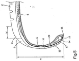
- Figure 5 shows the radial tyre of a fourth embodiment of the invention in partial cross-section.
- the side-cut shield 20 extends from the shoulder area 3 between the belt layers 5 and the plies 6 to the toe 16 of the tyre.
- the side-cut shield 20 extends from the edge facing the wing area 9 to a distance that accounts for approx. 32% of the width W of the shoulder area 3.
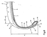
- Figures 6, 7 and 8 show the radial tyre of a fifth, sixth and seventh embodiment of the invention in partial cross-section.
- the side-cut shield 20 extends from the shoulder area 3 of the radial tyre, starting from its edge facing the wing area 9, to a distance that accounts for approx. 90% of the width W of the shoulder area 3.
- the side-cut shield 20 is also disposed in the shoulder area 3, between the belt layers 5 and the plies 6.
- the side-cut shield 20 extends similarly from the shoulder area 3 to the tyre bead area 11 around the bead wire 18 to a height that accounts for 7%, 12% ad 21% respectively of the height H of the radial tyre side, starting from the toe 16.
- the side-cut shield 20 is disposed between the inner liner 7 and the plies 6.
- FIGS 2-8 show various embodiments of the radial tyre of the invention.
- the embodiments are mutually different with regard to the location of the ends of the side-cut shield 20. It is obvious to those skilled in the art that the side-cut shield 20 can be disposed in the tyre in some other way than those shown in the figures.
- Figure 9 shows the mutual disposition of the filament arrays of the side-cut shield of the invention.
- the first filament array 21 is shown with continuous lines and the second filament array 22 with broken lines.
- the figure illustrates the angle ⁇ between the filament arrays 21 and 22.
Landscapes
- Engineering & Computer Science (AREA)
- Mechanical Engineering (AREA)
- Tires In General (AREA)
- Tyre Moulding (AREA)
- Heating, Cooling, Or Curing Plastics Or The Like In General (AREA)
Abstract
Description
- between the clinch an any ply turn-up provided or the bead wire in the heel, bead base and toe areas, and
- between the inner liner and the plies in the areas of the inner surface of the radial tyre.
- manufacturing a blank on a manufacturing drum by disposing on the manufacturing drum in the following order: among other things, plies extending from the first bead area to the second bead area of the radial tyre to be manufactured, two sidewalls on both sides of the central plane of the radial tyre to be manufactured and two shoulder areas on both sides of said central plane, the shoulder areas being disposed in the finished tyre between the surface in road contact and said sidewall during free rotation of the tyre,
- disposing on the blank a belt package comprising belt layers and the undertread and having a width substantially equal to the tread of the finished radial tyre,
- disposing the tread on the belt package, resulting in the tyre blank,
- vulcanising the tyre blank,
Claims (18)
- A radial tyre for vehicles comprising:characterised in that it further comprises two side-cut shields (20a, 20b) disposed in both sidewalls (10a, 10b) of the radial tyre, the side-cut shields (20a, 20b) comprising at least two plies with a first filament array (21), which consists of mutually substantially parallel filaments, and a second filament array (22), which consists of mutually substantially parallel filaments, the filaments in the first filament array (21) being at an angle α to the filaments of the second filament array (22), the angle α being 20° - 90°, and the side-cut shields (20a, 20b) being disposed to extend from the bead areas (11a, 11b) of the radial tyre to the shoulder areas (3a, 3b) of the radial tyre such that the edges of the side-cut shields (20a, 20b) facing the shoulder area (3a, 3b) are disposed between the belt layers (5) and the plies (6).Viewed in order, starting from the outer surface of the radial tyre, which gets into contact with the road, towards the inner parts of the radial tyre:a tread (1) in road contact, the tread comprising a surface (2) that is in road contact during free rotation of the tyre and two shoulder areas (3a, 3b) on both sides of the central plane (K) of the radial tyre,an undertread (4) having principally the same width as the tread (1),one or more belt layers (5) having substantially the same width as the tread (1),one or more plies (6), which extend from the first bead area (11a) to the second bead area (11b) of the radial tyre, the opposite side of the belt layers (5) of the plies (6) forming the inner surface (8) of the radial tyre together with the inner liner (7);In the following order, on both sides of the tread (1) symmetrically with the central plane (K) of the radial tyre:two wing areas (9a, 9b) of the tread (1) extending the shoulder areas (3a, 3b),two sidewalls (10a, 10b),two bead areas (11a, 11b),
- A radial tyre as defined in claim 1, characterised in that the angle α is 30° - 70°, preferably 40° - 60 °.
- A radial tyre as defined in claim 1 or 2, characterised in that the number of plies in the side-cut shield (20a, 20b) is 2-10, preferably 2-4.
- A radial tyre as defined in claim 3, characterised in that said plies are disposed overlapping in the side-cut shield (20a, 20b).
- A radial tyre as defined in any of the preceding claims, characterised in that the filament in said filament arrays (21, 22) are made of an organic or an inorganic material.
- A radial tyre as defined in claim 5, characterised in that said filaments are steel, polyamide, aromatic polyamide or rayon filaments.
- A radial tyre as defined in any of the preceding claims, characterised in that the sidewalls (10a, 10b) comprise, viewed from the outer surface towards the inner parts of the radial tyre, a sidewall (10a, 10b), any ply turn-ups (17a, 17b) provided, plies (6) and an inner liner (7).
- A radial tyre as defined in any of the preceding claims, characterised in that the bead areas (11a, 11b) comprise:viewed from the outer surface towards the inner parts of the radial tyre, a clinch (12a, 12b), any turn-ups (17a, 17b) of the plies (6), an apex (19a, 19b) and a bead wire (18a, 18b), plies (6) and an inner liner (7), andankles (13a, 13b), heels (14a, 14b), bead bases (15a, 15b) and toes (16a. 16b).
- A radial tyre as defined in any of the preceding claims, characterised in that the side-cut shields (20a, 20b) have been disposed on the sidewalls (10a, 10b) between the sidewall (10a, 10b) or the clinch (12a, 12b) and any turn-up (17a, 17b) of the plies (6) or the plies (6).
- A radial tyre as defined in any of the preceding claims, characterised in that the side-cut shields (20a, 20b) extend to the shoulder areas (3a, 3b), starting from their edge facing the wing areas (9a, 9b) to a distance that accounts for 5% - 100%, preferably 25%- 95% of the width (W) of the shoulder area (3a, 3b).
- A radial tyre as defined in any of claims 9-10, characterised in that the edges of the side-cut shields (20a, 20b) facing the bead areas (11a, 11b) are disposed substantially in the heel areas (14a, 14b) of the radial tyre.
- A radial tyre as defined in any of claims 9-10, characterised in that the edges of the side-cut shields (20a, 20b) facing the bead areas (11a, 11b) are disposed substantially in the bead bases (15a, 15b) of the radial tyre.
- A radial tyre as defined in any of claims 9-10, characterised in that the edges of the side-cut shields (20a, 20b) facing the bead areas (11a, 11b) are disposed substantially in the toes (16a, 16b) of the radial tyre.
- A radial tyre as defined in any of claims 8-10, characterised in that the side-cut shields (20a, 20b) are disposed to extend from the inner surface (8) of the radial tyre through the bead base (15a, 15b) to the shoulder areas (3a, 3b) of the radial tyre.
- A radial tyre as defined in claims 14, characterised in that the side-cut shields (20a, 20b) are disposed to extend from the inner surface (8) of the radial tyre, from a height that accounts for 3% - 80%, or preferably 5% - 30% of the height (H) of the side of the radial tyre, staring from the toe (16a, 16b), through the bead base (15a, 15b) to the shoulder areas (3a, 3b) of the radial tyre.
- A radial tyre as defined in any of claims 9-15, characterised in that the side-cut shields (20a, 20b) have been disposed in the bead areas (11a, 11b) of the radial tyre:between the clinch (12a, 12b) and any turn-up (17a, 17b) of the plies (6) or the bead wire (18a, 18b) in the areas of the heel (14a, 14b), the bead base (15a, 15b) and the toe (16a, 16b), andbetween the inner liner (7) and the plies (6) in the areas of the inner surface (8) of the radial tyre.
- A radial tyre as defined in any of the preceding claims, characterised in that the side-cut shields (20a, 20b) are disposed symmetrically on both sides of the peripheral central line (K) of the tread (1) of the radial tyre.
- A method for manufacturing the radial tyre of a vehicle, comprising:characterised in that the method further comprises: between the step of disposing the plies (6) and the sidewalls (10a, 10b) in the blank manufacture, a step of disposing on both the sidewalls (10a, 10b) of the radial tyre two side-cut shields (20a, 20b), which comprise at least two plies, which comprise a first filament array (21), which consists of mutually substantially parallel filaments, and a second filament array (22), which consists of mutually substantially parallel filaments, the filaments in the first filament array (21) being at an angle α relative to the filaments of the second filament array (22), the angle α being 20° - 90°, and the side-cut shields (20a, 20b) being disposed to extend from the bead areas (11a, 11b) of the radial tyre to the shoulder areas (3a, 3b) of the radial tyre such that the edges of the side-cut shields (20a, 20b) facing the shoulder area (3a, 3b) are disposed between the belt layers (5) and the plies (6).manufacturing a blank on a manufacturing drum by disposing on the manufacturing drum in the following order: among other things, plies (6) extending from the first bead area (11a) to the second bead area (11b) of the radial tyre to be manufactured, two sidewalls (10a, 10b) on both sides of the central plane (K) of the radial tyre to be manufactured and two shoulder areas (3a, 3b) on both sides of said central plane (K), the shoulder areas being disposed in the finished tyre between the surface (2) in road contact and said sidewall (10a, 10b) during free rotation of the tyre,disposing on the blank a belt package comprising belt layers (5) and the undertread (4) and having a width substantially equalling the tread of the finished radial tyre,disposing the tread (1) on the belt package, resulting in the tyre blank,vulcanising the tyre blank,
Applications Claiming Priority (4)
| Application Number | Priority Date | Filing Date | Title |
|---|---|---|---|
| FI20000800A FI20000800A0 (en) | 2000-04-05 | 2000-04-05 | Radial tire for working machine |
| FI20000800 | 2000-04-05 | ||
| FI20002330 | 2000-10-24 | ||
| FI20002330A FI113026B (en) | 2000-04-05 | 2000-10-24 | Radial tires for vehicles |
Publications (2)
| Publication Number | Publication Date |
|---|---|
| EP1142731A2 true EP1142731A2 (en) | 2001-10-10 |
| EP1142731A3 EP1142731A3 (en) | 2003-08-13 |
Family
ID=26160986
Family Applications (1)
| Application Number | Title | Priority Date | Filing Date |
|---|---|---|---|
| EP01660060A Ceased EP1142731A3 (en) | 2000-04-05 | 2001-04-04 | Radial tyre for vehicles |
Country Status (4)
| Country | Link |
|---|---|
| US (1) | US6691757B2 (en) |
| EP (1) | EP1142731A3 (en) |
| CA (1) | CA2342704A1 (en) |
| FI (1) | FI113026B (en) |
Cited By (2)
| Publication number | Priority date | Publication date | Assignee | Title |
|---|---|---|---|---|
| EP1535761A1 (en) * | 2003-11-27 | 2005-06-01 | Continental Aktiengesellschaft | Pneumatic tire |
| CN111163948A (en) * | 2017-10-02 | 2020-05-15 | 米其林集团总公司 | Tires with reinforced lower area |
Families Citing this family (7)
| Publication number | Priority date | Publication date | Assignee | Title |
|---|---|---|---|---|
| WO2008149588A1 (en) * | 2007-06-05 | 2008-12-11 | Sumitomo Rubber Industries, Ltd. | Rubber composition for tire, tire member, rubber composition for base tread, base tread, and tire |
| US20090095397A1 (en) * | 2007-10-15 | 2009-04-16 | Robert Anthony Neubauer | Floating two-ply tire |
| US20100051162A1 (en) * | 2008-08-29 | 2010-03-04 | Robert Anthony Neubauer | Modular two-ply tire with directional side plies |
| US20100108231A1 (en) * | 2008-10-30 | 2010-05-06 | E. I. Du Pont De Nemours And Company | Non-load bearing cut resistant tire side- wall component and tire containing said component, and processes for making same |
| US20100108225A1 (en) * | 2008-10-30 | 2010-05-06 | E. I. Du Pont De Nemours And Company | Non-Load Bearing Cut Resistant Tire Side-wall Component Comprising Knitted Textile Fabric, Tire Containing Said Component, and Processes for Making Same |
| US20100108218A1 (en) * | 2008-10-30 | 2010-05-06 | E. I. Du Pont De Nemours And Company | Extensible non-load bearing cut resistant tire side-wall component cotaining elastomeric filament, tire containing said component, and processes for making same |
| US10895689B2 (en) * | 2018-11-26 | 2021-01-19 | Globalfoundries Inc. | Switchable and reconfigurable grating couplers |
Family Cites Families (16)
| Publication number | Priority date | Publication date | Assignee | Title |
|---|---|---|---|---|
| FR1418988A (en) * | 1964-10-14 | 1965-11-26 | Michelin & Cie | Improvements to tire casings |
| FR2261888B1 (en) * | 1974-02-26 | 1976-12-10 | Kleber Colombes | |
| JPS5237303A (en) * | 1975-09-18 | 1977-03-23 | Bridgestone Corp | Light air tire having thin side wall rubber and method of fabricating the same |
| JPS52116504A (en) * | 1976-03-26 | 1977-09-30 | Bridgestone Corp | Pneumatic tire having superior side endurability against breakage with coil filament as reinforcing element for wild ground |
| US5164029A (en) * | 1976-11-22 | 1992-11-17 | Sumitomo Rubber Industries, Ltd. | Radial tire for high load with excellent vibration damping performance |
| IT1075633B (en) | 1977-04-07 | 1985-04-22 | Pirelli | IMPROVEMENT TO RADIAL TIRES PROVIDED WITH STRENGTHENING IN THE SIDES |
| JPS5920707A (en) * | 1982-07-23 | 1984-02-02 | Sumitomo Rubber Ind Ltd | Tire for motorcycle |
| JPS621605A (en) | 1985-06-27 | 1987-01-07 | Yokohama Rubber Co Ltd:The | Pneumatic tire |
| JPS6288601A (en) * | 1985-10-14 | 1987-04-23 | Sumitomo Rubber Ind Ltd | Tire for motorcycle |
| JPS6467405A (en) * | 1987-09-08 | 1989-03-14 | Ohtsu Tire & Rubber Co Ltd | Pneumatic radial tire |
| IT1243872B (en) * | 1990-10-29 | 1994-06-28 | Pirelli Transmissioni Ind Spa | RADIAL TIRE WITH SIDE REINFORCEMENT ELEMENT. |
| JP3091480B2 (en) * | 1990-11-30 | 2000-09-25 | 住友ゴム工業株式会社 | Pneumatic radial tire |
| JPH05246210A (en) * | 1991-12-30 | 1993-09-24 | Sumitomo Rubber Ind Ltd | Radial tire for motorcycle |
| US5392830A (en) | 1993-03-10 | 1995-02-28 | General Tire, Inc. | Protective barrier for tire sidewall |
| JPH11227424A (en) * | 1998-02-18 | 1999-08-24 | Bridgestone Corp | Pneumatic safety tire |
| JP2000025411A (en) * | 1998-05-01 | 2000-01-25 | Bridgestone Corp | Pneumatic tire for passenger car |
-
2000
- 2000-10-24 FI FI20002330A patent/FI113026B/en not_active IP Right Cessation
-
2001
- 2001-04-04 EP EP01660060A patent/EP1142731A3/en not_active Ceased
- 2001-04-04 CA CA002342704A patent/CA2342704A1/en not_active Abandoned
- 2001-04-04 US US09/826,553 patent/US6691757B2/en not_active Expired - Lifetime
Cited By (2)
| Publication number | Priority date | Publication date | Assignee | Title |
|---|---|---|---|---|
| EP1535761A1 (en) * | 2003-11-27 | 2005-06-01 | Continental Aktiengesellschaft | Pneumatic tire |
| CN111163948A (en) * | 2017-10-02 | 2020-05-15 | 米其林集团总公司 | Tires with reinforced lower area |
Also Published As
| Publication number | Publication date |
|---|---|
| CA2342704A1 (en) | 2001-10-05 |
| US20010047841A1 (en) | 2001-12-06 |
| FI20002330A0 (en) | 2000-10-24 |
| EP1142731A3 (en) | 2003-08-13 |
| US6691757B2 (en) | 2004-02-17 |
| FI113026B (en) | 2004-02-27 |
| FI20002330L (en) | 2001-10-06 |
Similar Documents
| Publication | Publication Date | Title |
|---|---|---|
| US9108472B2 (en) | Pneumatic heavy-duty tire having circumferential reinforcing layer and sipes | |
| KR101773625B1 (en) | Motorcycle tire for running on rough terrain | |
| US7048022B2 (en) | Tire tread with anti-puncture pads | |
| JP5843418B2 (en) | Off-road tire | |
| JP6228476B2 (en) | Motorcycle tires for running on rough terrain | |
| US4865101A (en) | Radial ply tire | |
| EP1142731A2 (en) | Radial tyre for vehicles | |
| DE112022004010T5 (en) | Tires | |
| JP2004083001A (en) | Pneumatic radial tire | |
| EP3895910B1 (en) | Tire with cut protector belt structure | |
| US20070137758A1 (en) | Radial farm tire for high clearance sprayers | |
| JP2009184371A (en) | Pneumatic tire | |
| US11541694B2 (en) | Studdable tire and pneumatic tire | |
| JPH06320914A (en) | Pneumatic radial tire for heavy load | |
| JP2000079806A (en) | Radial tires for heavy loads | |
| JP2014118011A (en) | Pneumatic tire | |
| JPH09207518A (en) | Pneumatic tire | |
| JP2016165923A (en) | Pneumatic tire | |
| JPH11115412A (en) | Pneumatic radial tire for heavy duty | |
| JP3686203B2 (en) | Heavy duty radial tires | |
| JPH11321216A (en) | Heavy duty tire | |
| JP3595414B2 (en) | Pneumatic radial tire for heavy loads | |
| RU2797953C1 (en) | Air tire | |
| US20230191839A1 (en) | Pneumatic tire | |
| JP3177363B2 (en) | Pneumatic radial tire |
Legal Events
| Date | Code | Title | Description |
|---|---|---|---|
| PUAI | Public reference made under article 153(3) epc to a published international application that has entered the european phase |
Free format text: ORIGINAL CODE: 0009012 |
|
| AK | Designated contracting states |
Kind code of ref document: A2 Designated state(s): AT BE CH CY DE DK ES FI FR GB GR IE IT LI LU MC NL PT SE TR |
|
| AX | Request for extension of the european patent |
Free format text: AL;LT;LV;MK;RO;SI |
|
| PUAL | Search report despatched |
Free format text: ORIGINAL CODE: 0009013 |
|
| AK | Designated contracting states |
Designated state(s): AT BE CH CY DE DK ES FI FR GB GR IE IT LI LU MC NL PT SE TR |
|
| AX | Request for extension of the european patent |
Extension state: AL LT LV MK RO SI |
|
| 17P | Request for examination filed |
Effective date: 20040124 |
|
| AKX | Designation fees paid |
Designated state(s): SE |
|
| REG | Reference to a national code |
Ref country code: DE Ref legal event code: 8566 |
|
| 17Q | First examination report despatched |
Effective date: 20050629 |
|
| STAA | Information on the status of an ep patent application or granted ep patent |
Free format text: STATUS: THE APPLICATION HAS BEEN REFUSED |
|
| 18R | Application refused |
Effective date: 20071206 |