EP1142687A2 - Method for determining molding characteristic and injection molding machine - Google Patents
Method for determining molding characteristic and injection molding machine Download PDFInfo
- Publication number
- EP1142687A2 EP1142687A2 EP01303166A EP01303166A EP1142687A2 EP 1142687 A2 EP1142687 A2 EP 1142687A2 EP 01303166 A EP01303166 A EP 01303166A EP 01303166 A EP01303166 A EP 01303166A EP 1142687 A2 EP1142687 A2 EP 1142687A2
- Authority
- EP
- European Patent Office
- Prior art keywords
- pressure data
- molding
- data
- injection
- detected
- Prior art date
- Legal status (The legal status is an assumption and is not a legal conclusion. Google has not performed a legal analysis and makes no representation as to the accuracy of the status listed.)
- Granted
Links
Images



Classifications
-
- B—PERFORMING OPERATIONS; TRANSPORTING
- B29—WORKING OF PLASTICS; WORKING OF SUBSTANCES IN A PLASTIC STATE IN GENERAL
- B29C—SHAPING OR JOINING OF PLASTICS; SHAPING OF MATERIAL IN A PLASTIC STATE, NOT OTHERWISE PROVIDED FOR; AFTER-TREATMENT OF THE SHAPED PRODUCTS, e.g. REPAIRING
- B29C45/00—Injection moulding, i.e. forcing the required volume of moulding material through a nozzle into a closed mould; Apparatus therefor
- B29C45/17—Component parts, details or accessories; Auxiliary operations
- B29C45/76—Measuring, controlling or regulating
- B29C45/77—Measuring, controlling or regulating of velocity or pressure of moulding material
-
- B—PERFORMING OPERATIONS; TRANSPORTING
- B29—WORKING OF PLASTICS; WORKING OF SUBSTANCES IN A PLASTIC STATE IN GENERAL
- B29C—SHAPING OR JOINING OF PLASTICS; SHAPING OF MATERIAL IN A PLASTIC STATE, NOT OTHERWISE PROVIDED FOR; AFTER-TREATMENT OF THE SHAPED PRODUCTS, e.g. REPAIRING
- B29C45/00—Injection moulding, i.e. forcing the required volume of moulding material through a nozzle into a closed mould; Apparatus therefor
- B29C45/17—Component parts, details or accessories; Auxiliary operations
- B29C45/76—Measuring, controlling or regulating
- B29C45/768—Detecting defective moulding conditions
-
- B—PERFORMING OPERATIONS; TRANSPORTING
- B29—WORKING OF PLASTICS; WORKING OF SUBSTANCES IN A PLASTIC STATE IN GENERAL
- B29C—SHAPING OR JOINING OF PLASTICS; SHAPING OF MATERIAL IN A PLASTIC STATE, NOT OTHERWISE PROVIDED FOR; AFTER-TREATMENT OF THE SHAPED PRODUCTS, e.g. REPAIRING
- B29C2945/00—Indexing scheme relating to injection moulding, i.e. forcing the required volume of moulding material through a nozzle into a closed mould
- B29C2945/76—Measuring, controlling or regulating
- B29C2945/76003—Measured parameter
- B29C2945/76006—Pressure
-
- B—PERFORMING OPERATIONS; TRANSPORTING
- B29—WORKING OF PLASTICS; WORKING OF SUBSTANCES IN A PLASTIC STATE IN GENERAL
- B29C—SHAPING OR JOINING OF PLASTICS; SHAPING OF MATERIAL IN A PLASTIC STATE, NOT OTHERWISE PROVIDED FOR; AFTER-TREATMENT OF THE SHAPED PRODUCTS, e.g. REPAIRING
- B29C2945/00—Indexing scheme relating to injection moulding, i.e. forcing the required volume of moulding material through a nozzle into a closed mould
- B29C2945/76—Measuring, controlling or regulating
- B29C2945/76003—Measured parameter
- B29C2945/7604—Temperature
-
- B—PERFORMING OPERATIONS; TRANSPORTING
- B29—WORKING OF PLASTICS; WORKING OF SUBSTANCES IN A PLASTIC STATE IN GENERAL
- B29C—SHAPING OR JOINING OF PLASTICS; SHAPING OF MATERIAL IN A PLASTIC STATE, NOT OTHERWISE PROVIDED FOR; AFTER-TREATMENT OF THE SHAPED PRODUCTS, e.g. REPAIRING
- B29C2945/00—Indexing scheme relating to injection moulding, i.e. forcing the required volume of moulding material through a nozzle into a closed mould
- B29C2945/76—Measuring, controlling or regulating
- B29C2945/76003—Measured parameter
- B29C2945/76083—Position
-
- B—PERFORMING OPERATIONS; TRANSPORTING
- B29—WORKING OF PLASTICS; WORKING OF SUBSTANCES IN A PLASTIC STATE IN GENERAL
- B29C—SHAPING OR JOINING OF PLASTICS; SHAPING OF MATERIAL IN A PLASTIC STATE, NOT OTHERWISE PROVIDED FOR; AFTER-TREATMENT OF THE SHAPED PRODUCTS, e.g. REPAIRING
- B29C2945/00—Indexing scheme relating to injection moulding, i.e. forcing the required volume of moulding material through a nozzle into a closed mould
- B29C2945/76—Measuring, controlling or regulating
- B29C2945/76003—Measured parameter
- B29C2945/7611—Velocity
-
- B—PERFORMING OPERATIONS; TRANSPORTING
- B29—WORKING OF PLASTICS; WORKING OF SUBSTANCES IN A PLASTIC STATE IN GENERAL
- B29C—SHAPING OR JOINING OF PLASTICS; SHAPING OF MATERIAL IN A PLASTIC STATE, NOT OTHERWISE PROVIDED FOR; AFTER-TREATMENT OF THE SHAPED PRODUCTS, e.g. REPAIRING
- B29C2945/00—Indexing scheme relating to injection moulding, i.e. forcing the required volume of moulding material through a nozzle into a closed mould
- B29C2945/76—Measuring, controlling or regulating
- B29C2945/76003—Measured parameter
- B29C2945/76163—Errors, malfunctioning
-
- B—PERFORMING OPERATIONS; TRANSPORTING
- B29—WORKING OF PLASTICS; WORKING OF SUBSTANCES IN A PLASTIC STATE IN GENERAL
- B29C—SHAPING OR JOINING OF PLASTICS; SHAPING OF MATERIAL IN A PLASTIC STATE, NOT OTHERWISE PROVIDED FOR; AFTER-TREATMENT OF THE SHAPED PRODUCTS, e.g. REPAIRING
- B29C2945/00—Indexing scheme relating to injection moulding, i.e. forcing the required volume of moulding material through a nozzle into a closed mould
- B29C2945/76—Measuring, controlling or regulating
- B29C2945/76177—Location of measurement
- B29C2945/7618—Injection unit
- B29C2945/76187—Injection unit screw
-
- B—PERFORMING OPERATIONS; TRANSPORTING
- B29—WORKING OF PLASTICS; WORKING OF SUBSTANCES IN A PLASTIC STATE IN GENERAL
- B29C—SHAPING OR JOINING OF PLASTICS; SHAPING OF MATERIAL IN A PLASTIC STATE, NOT OTHERWISE PROVIDED FOR; AFTER-TREATMENT OF THE SHAPED PRODUCTS, e.g. REPAIRING
- B29C2945/00—Indexing scheme relating to injection moulding, i.e. forcing the required volume of moulding material through a nozzle into a closed mould
- B29C2945/76—Measuring, controlling or regulating
- B29C2945/76177—Location of measurement
- B29C2945/7618—Injection unit
- B29C2945/76204—Injection unit injection piston cylinder
-
- B—PERFORMING OPERATIONS; TRANSPORTING
- B29—WORKING OF PLASTICS; WORKING OF SUBSTANCES IN A PLASTIC STATE IN GENERAL
- B29C—SHAPING OR JOINING OF PLASTICS; SHAPING OF MATERIAL IN A PLASTIC STATE, NOT OTHERWISE PROVIDED FOR; AFTER-TREATMENT OF THE SHAPED PRODUCTS, e.g. REPAIRING
- B29C2945/00—Indexing scheme relating to injection moulding, i.e. forcing the required volume of moulding material through a nozzle into a closed mould
- B29C2945/76—Measuring, controlling or regulating
- B29C2945/76177—Location of measurement
- B29C2945/7618—Injection unit
- B29C2945/7621—Injection unit nozzle
-
- B—PERFORMING OPERATIONS; TRANSPORTING
- B29—WORKING OF PLASTICS; WORKING OF SUBSTANCES IN A PLASTIC STATE IN GENERAL
- B29C—SHAPING OR JOINING OF PLASTICS; SHAPING OF MATERIAL IN A PLASTIC STATE, NOT OTHERWISE PROVIDED FOR; AFTER-TREATMENT OF THE SHAPED PRODUCTS, e.g. REPAIRING
- B29C2945/00—Indexing scheme relating to injection moulding, i.e. forcing the required volume of moulding material through a nozzle into a closed mould
- B29C2945/76—Measuring, controlling or regulating
- B29C2945/76344—Phase or stage of measurement
- B29C2945/76381—Injection
-
- B—PERFORMING OPERATIONS; TRANSPORTING
- B29—WORKING OF PLASTICS; WORKING OF SUBSTANCES IN A PLASTIC STATE IN GENERAL
- B29C—SHAPING OR JOINING OF PLASTICS; SHAPING OF MATERIAL IN A PLASTIC STATE, NOT OTHERWISE PROVIDED FOR; AFTER-TREATMENT OF THE SHAPED PRODUCTS, e.g. REPAIRING
- B29C2945/00—Indexing scheme relating to injection moulding, i.e. forcing the required volume of moulding material through a nozzle into a closed mould
- B29C2945/76—Measuring, controlling or regulating
- B29C2945/76494—Controlled parameter
- B29C2945/76531—Temperature
-
- B—PERFORMING OPERATIONS; TRANSPORTING
- B29—WORKING OF PLASTICS; WORKING OF SUBSTANCES IN A PLASTIC STATE IN GENERAL
- B29C—SHAPING OR JOINING OF PLASTICS; SHAPING OF MATERIAL IN A PLASTIC STATE, NOT OTHERWISE PROVIDED FOR; AFTER-TREATMENT OF THE SHAPED PRODUCTS, e.g. REPAIRING
- B29C2945/00—Indexing scheme relating to injection moulding, i.e. forcing the required volume of moulding material through a nozzle into a closed mould
- B29C2945/76—Measuring, controlling or regulating
- B29C2945/76929—Controlling method
- B29C2945/76939—Using stored or historical data sets
- B29C2945/76943—Using stored or historical data sets compare with thresholds
-
- B—PERFORMING OPERATIONS; TRANSPORTING
- B29—WORKING OF PLASTICS; WORKING OF SUBSTANCES IN A PLASTIC STATE IN GENERAL
- B29C—SHAPING OR JOINING OF PLASTICS; SHAPING OF MATERIAL IN A PLASTIC STATE, NOT OTHERWISE PROVIDED FOR; AFTER-TREATMENT OF THE SHAPED PRODUCTS, e.g. REPAIRING
- B29C49/00—Blow-moulding, i.e. blowing a preform or parison to a desired shape within a mould; Apparatus therefor
- B29C49/42—Component parts, details or accessories; Auxiliary operations
- B29C49/78—Measuring, controlling or regulating
Definitions
- the present invention relates to a method for determining molding characteristic and to an injection molding machine which facilitates identifying a problem when a molding problem occurs during molding by the injection molding machine.
- Resins of the same kind have different resin properties between their batches or need different drying temperature, time for being left or mixing ratio of regenerant, which all require the examination of the resin properties.
- the resin properties are examined using a special measuring apparatus.
- the present invention has a object to provide a method for determining molding characteristic and an injection molding machine which can determine, when a problem occurs in the injection molding machine, whether the problem is caused by a molding machine, resin or a mold.
- the present invention provides for resin to be injected by means of a nozzle into an injection molding machine left open to allow detecting of an injection pressure produced at that time by a pressure sensor, stores pressure data detected by the pressure sensor as reference pressure data together with the screw position data or the elapse of time in storing means, and obtains detected pressure data with respect to the screw position or time when the resin having a different condition such as difference in resin lots, difference in drying temperature, difference in mixing ratio of regenerant or difference in time for being left injected with the nozzle left open under the same molding condition as that used in an injection with the nozzle left open.
- Variation in the molding characteristic is determined by display of detected pressure data and the reference pressure data stored in the storing means on displaying means.
- resin may be injected with a nozzle left open under each molding condition in compliance with scheduled molding condition to obtain reference pressure data under each molding data to be stored in storing means, and the resin having a different condition is injected with the nozzle left open under a specific or an optional molding condition in obtaining the reference pressure data to obtain detected pressure data and to determine variation of molding characteristic by displaying the reference pressure data having the same molding condition as that used in obtaining the detected pressure data and the detected pressure data on displaying means. If reference pressure data includes no data showing the same molding condition, the reference pressure data with respect to the corresponding molding condition is found by interpolating from reference pressure data to be displayed stored in the sorting means.
- each detected pressure data is obtained under the same scheduled molding condition as in obtaining the reference pressure data to display the detected pressure data and the reference pressure data stored in the storing means correspondingly to the molding condition on the displaying means to determine variation of the molding characteristic.
- the molding condition scheduled includes at least conditions of temperatures of a nozzle and a cylinder and a condition of injection speed.
- Data such as the molding condition in obtaining the data, date, kind of the resin are simultaneously stored when the reference pressure data is detected to be stored.
- a controller of the injection molding machine is connected to the personal computer by communication means, the reference pressure data is stored in the storing means provided on the personal computer, and the reference pressure data and detected pressure data are input in the personal computer to be displayed on said displaying means.
- data such as a code for identifying the molding machine, the molding condition in obtaining the data, date, kind of the resin are simultaneously stored together with the reference pressure data.
- an injection molding machine is provided with a pressure sensor for detecting an injection pressure; storing means for injecting resin with a nozzle in an injection molding machine is left open to store a pressure detected by said pressure sensor as reference pressure data together with the screw position data or the lapse of time; and comparing means for outputting an alarm when detected pressure data with respect to the screw position and time obtained by injecting the resin having a different condition with said nozzle left open under the same molding condition as that used in an injection with said nozzle left open exceeds setting monitoring width of said reference pressure data.
- FIG. 1 is a schematic view of an injection mechanism of an injection molding machine using a method for determining molding characteristic according to the present invention.
- reference numeral 1 denotes a mold; 2, a cylinder; 3, a screw; 4, a hopper for supplying the cylinder with pellets of resin; 5, a front plate which forms the injection mechanism; 6, a rear plate.
- a plurality of guide bars 7 are provided between the front plate 5 and the rear plate 6, and a pressure plate 8 guided by the guide bars 7 is arranged movably back and forth (right and left in the figure).
- the pressure plate 8 is rotatably mounted with a base of the screw 3.
- the base of the screw 3 is mounted with a pulley and the screw 3 is rotatably driven by a servomotor M1 for rotating the screw through a driving pulley, a timing belt and the like.
- the pressure plate 8 is mounted through a pressure sensor (load cell) 9 with a ball nut 10.
- the ball nut 10 is screwed on a ball screw 11.
- the ball screw 11 is rotatably driven by a servomotor M2 for injection through the driving pulley, timing belt and a driven pulley.
- the cylinder 2 and a nozzle 12 are mounted with a band heater and a temperature sensor 13 for detecting temperatures of the nozzle and heater.
- the servomotor M2 for injection is driven to rotate the ball screw 11, to move forward (left in FIG. 1) the nut 10 screwed on the ball screw 11 and the pressure plate 8 and to also move forward the screw 3 to inject melted resin from the cylinder 2 into a cavity of the mold 1.
- an injection pressure is detected by the pressure sensor (load cell) 9.
- FIG. 2 is a block diagram of a controller 20 of this injection molding machine.
- the controller 20 has a CPU 35 for CNC which is a microprocessor for controlling numerical values, a CPU 31 for PMC (Programmable Machine Controller) which is a microprocessor for a programmable machine controller, a CPU 32 for servo which is a microprocessor for servo control and a CPU 30 for pressure monitor which samples signals from the pressure sensor 9 through an A/D transducer 22 to be stored in a RAM 24. Information can be transmitted between each microprocessor by selecting mutual input and output through a bus 41.
- PMC Programmable Machine Controller
- ROM 25 which stores a sequence program or the like for controlling sequence operation of the injection molding machine and a RAM 26 used for temporary storage or the like of calculated data.
- ROM 37 which stores an automatic operation program or the like for totally controlling the injection molding machine and a RAM 38 used for the temporary storage of the calculated data.
- ROM 27 which stores a control program exclusively for the servo control which deals with a position loop, speed loop and current loop and a RAM 28 used for the temporary storage of the data.
- ROM 23 which stores a control program of control effected by the CPU 30 for pressure monitor and the above described RAM 24 which stores the pressure or the like detected by the pressure sensor 9.
- a servo amplifier which drives the servomotor of each shaft for such as clamping, the injection, the rotation of the screw and an ejector, and output from a position/speed detector mounted on the servomotor of each shaft is put into feedback to the CPU 32 for servo.
- the current position of each shaft is calculated by the CPU 32 for servo on the basis of a feedback signal of position from the position/speed detector and renewably stored in a register for storing the current position of each shaft.
- FIG. 2 shows, among the shafts, only the servo amplifier 29, the servomotor M2 and position/speed detector 21, which relate to the shaft for the injection, however, the same applies, in their configuration, to the servo amplifiers, servomotors and position/speed detectors which relate to individual shafts for rotation of a screw, mold clamping, and moving of an injection mechanism.
- An interface 33 is an input and output interface for receiving signals from the temperature sensor 13, a limit switch and a control panel provided on each part of a body of the injection molding machine and transmitting various commands to peripheral equipment or the like of the injection molding machine.
- a manual data input unit 39 with displaying means constituted by CRT or liquid crystal is connected to the bus 41 through a displaying circuit 36, which can carry out selection of graph display screens or function menus and input operation of various data.
- the manual data input unit 39 is provided with a numeric keypad for inputting data of numerical values and various function keys.
- Reference numeral 40 denotes a communication interface and the controller of the injection molding machine is connected to a personal computer via the interface 40.
- the RAM 34 for storing data constituted by a nonvolatile memory is a memory for storing molding data which stores molding conditions, various setting values, parameter, macro parameter or the like with respect to the injection molding operation.
- the reference pressure data are stored in the RAM 34 for storing data.
- the CPU 31 for PMC controls the sequence operation of the whole injection molding machine and the CPU 35 for CNC distributes a movement command to the servomotor of each shaft on the basis of the molding condition stored in an operation program of the ROM 37 or the RAM 34 for storing data.
- the CPU 32 for servo carries out the servo control such as the position loop control, speed loop control and current loop control, namely digital servo processing, on the basis of the movement command distributed to each shaft and the feedback signals of the position and speed detected by the position/speed detector 11 and the like.
- the above described configuration is substantially the same as that of a controller of an electric injection molding machine.
- the molding characteristic depending upon the resin to be used is easily determined.
- the pressure data to be reference is first obtained.
- a certain condition may be used.
- the molding condition during a good molded product being obtained may be used.
- the injection mechanism is moved to separate the nozzle 12 from the mold and to thereby leave the nozzle open. Then, a obtaining process of the reference pressure data is started.
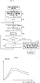
- FIG. 3 is a flow chart of the pressure sampling process for obtaining the reference pressure data, carried out by the CPU 30 for pressure monitor.
- sampling number N corresponding to preset maximum injection time is set in the register (step A1).
- An index n is set to "0" (step A2) to read a current injection pressure Pr detected by the pressure sensor 9 through the A/D transducer 22 and to read screw position data SP from a current position storing register for storing the current screw position (step A3).
- the read current injection pressure Pr and the screw position data SP are stored in the RAM 24 as Pr(n) and SP(n) (step A4).
- step A5 it is determined whether the index n reaches the setting sampling number N (step A5) and if not, the index n is subjected to increment by "1" (step A6), returning to the step 3.
- injection pressure data Pr(1) to Pr (N) and screw position data SP(1) to SP(N) stored in the RAM 34 are stored as the reference pressure data Pr0(1) to Pr0(N) and reference position data SP0(1) to SP0(N) in the RAM 34 for storing data constituted by the nonvolatile memory.
- a molding machine code is also stored which identifies the molding condition, date, kind of the resin and the injection molding machine (step A7).
- the pressure data may be stored as the reference pressure data of a function of position, corresponding to the screw position, however, the reference pressure data corresponding to the screw position is actually obtained by storing the injection pressure data Pr(1) to Pr (N) and the screw position data SP(1) to SP(N) in each sampling.
- the reference pressure data and pressure position data may be obtained by a plurality of injection rather than one injection with the nozzle left open.
- the processes of steps A1 to A7 are carried out in every injection.
- the number of injection is counted by a counter and if it does not reach the setting number, the injection pressure data Pr(1) to Pr (N) and the screw position data SP(1) to SP(N) are stored in another memory of the RAM 24 or the RAM 34 for storing data.
- an average of each sampling of the stored injection pressure data Pr(1) to Pr (N) is found and a group of the data consisting of the average values in each sampling is stored as the reference pressure data Pr0(1) to Pr0(N) in the RAM 34 for storing data.
- the injection pressure data Pr(1) to Pr (N) is stored in the RAM 34 for storing data in the form of the average of the pressure data corresponding to the screw position obtained on the basis of respective screw position data SP(1) to SP(N) as the reference pressure data which is a function of position.
- the nozzle of the injection molding machine described above is left open to carry out the injection under the same molding condition as that used in obtaining the reference pressure data. Then, in the same sampling cycle as in the process shown in FIG. 3, the injection pressure detected by the pressure sensor 9 is obtained in the RAM 24 as the pressure data Pr(1) to Pr (N) and simultaneously the screw position data SP(1) to SP(N) is obtained.
- FIG. 4 is a graphical representation of the above mentioned reference pressure data Pr0(1) to Pr0(N) and detected pressure data Pr(1) to Pr (N).
- the molding machine code is also displayed for confirmation which identifies the molding condition, date, kind of the resin and injection molding machine stored together with the reference pressure data.
- the pressure data Pr(1) to Pr (N) with respect to the screw position data SP(1) to SP(N) stored in the RAM 24 is displayed and the reference pressure data Pr0(1) to Pr0(N) with respect to the reference position data SP0(1) to SP0(N) stored in the RAM 34 for storing data is displayed to be compared.
- the resin properties vary by various reasons such as the difference in the lots in production of the resin, difference in degree of drying of the resin, difference in storing condition of the resin, difference in lapsed time after the production of the resin and difference in mixing ratio of the regenerant so that molding under the same molding condition cannot always produce the good molded product and that the defective molding may occur.
- the pressure data Pr(1) to Pr (N) is obtained with the nozzle of the injection molding machine left open under the same molding condition as that used in obtaining the reference pressure data.
- the pressure data Pr(1) to Pr (N) becomes substantially identical to the reference pressure data Pr0(1) to Pr0(N) so that two display waveforms which display each data becomes substantially identical.
- the waveforms are not substantially identical, it is determined that the molding characteristic is different and that there is the problem in the resin or the molding machine.
- the controller of the injection molding machine may set a monitoring width with respect to the reference pressure data Pr0(1) to Pr0(N) and raise an alarm when the detected pressure data Pr(1) to Pr (N) exceeds the monitoring width.
- a lower limit width PBL and an upper limit width are set in advance with respect to the reference pressure data Pr0(1) to Pr0(N) and the injection is started with the nozzle of the injection molding machine left open.
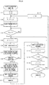
- the pressure data is sampled in every sampling cycle to allow the PMC processor 31 to carry out the process of determining defection as shown in FIG. 5.
- the index n and a flag NG are set to "0" (step B1). It is determined whether the current pressure Pr is within the set monitoring width with respect to the reference pressure data Pr0(n) or not by determining whether the value of the current injection pressure Pr read out is higher than the value obtained by subtracting the setting lower width PBL from the reference pressure data Pr0(n) and lower than the value obtained by adding the setting upper width PBU to the reference pressure data Pr0(n)(step B2).
- step B3 When the current pressure Pr is within the monitoring width, it is determined that whether the index n reaches the setting sampling number N (step B3) and if not, the index n is subjected to increment by "1" (step B4), returning to the step B2 to repeat the processes of the steps B2 to B4 in every sampling cycle.
- the flag NG is set to "1" (step B5), moving to the step B3.
- the flag NG is set to "1" in the step 5
- the process may be finished as it is.
- the process of determining the defection as shown in FIG. 5 is carried out with the current injection pressure being sampled.
- the process in FIG. 5 may be carried out to determine the defection.
- the only difference from the above example is that the current pressure Pr becomes the detected pressure data Pr(1) to Pr (N) corresponding to the index n.
- one reference pressure data Pr0(1) to Pr0(N) is obtained under a certain molding condition, and the injection pressure obtained when the injection is carried out with the nozzle left open under the same molding condition as this is compared with the reference pressure data to determine the molding characteristic.
- FIG. 6 is a flow chart of a process according to the second embodiment where a plurality of molding conditions are scheduled to obtain, under each molding condition, the reference pressure data Pr0(1) to Pr0(N) and the reference position data SP0(1) to SP0(N).
- a plurality of setting temperatures T(0) to T(Y) and a plurality of setting speeds V(0) to V(X) are set with respect to the cylinder and nozzle and are stored in the RAM 34 for storing data in advance.
- the CPU 31 for PMC sets the index i and j to "0" (step C1).
- the set temperature T(i) (T(0) at first) is read out to be set as the setting temperature T in a memory for setting the molding condition in effecting the molding operation.
- the temperature is started to be raised at the set temperature T (steps C2 and C3).
- Temperature Ta detected from the temperature sensor 13 through the input and output interface 33 is waited to reach the setting temperature T (step C4), and when it reaches the setting temperature T, the speed V(i) (V(0) at first) is read out to be set as the setting speed V in the memory for setting the molding condition (step C5).
- the injection is started at this setting speed V (step C6).
- the CPU 30 for pressure monitor samples the injection pressure detected by the pressure sensor 9 to be stored in the RAM 24 as the pressure data Pr(1) to Pr (N) and simultaneously the screw position data SP(1) to SP(N) is stored (steps C7 and C8).
- the detected pressure data Pr(1) to Pr (N) and the screw position data SP(1) to SP(N) stored in the RAM 24 are stored in the RAM 34 for storing data as the reference pressure data Pr0(1) to Pr0(N) and the reference position data SP0(1) to SP0(N).
- the temperature, speed or other molding conditions, date of obtaining the data and kind of the resin are also stored corresponding to the reference pressure data Pr0(1) to Pr0(N) (step C9).
- the injection unit is moved forward to abut the nozzle against a flat plate mounted instead of the mold to close an opening of the nozzle. Then, the measuring process is carried out, and after the completion of the measurement, the injection unit is moved backward to leave the nozzle open (steps C10 to C12).
- PT(j,i) a data group of the reference pressure data Pr0(1) to Pr0(N) obtained under the molding condition of the setting temperature at Tj and setting speed at Vi.
- PT(j,i) a data group of the reference position data SP0(1) to SP0(N) is referred to as PT(j,i).
- the index j is subjected to increment by "1" to determine whether the index j exceeds the setting value Y and if not, the index j is subjected to increment by "1" (steps C15 to C17) to carry out the processes after the step C2.
- the setting temperature T(j) shown by the index j is read out to be set in the memory for setting the molding condition and to carry out the injection at this temperature.
- step C16 the processes of the steps C2 to C17 are repeated before the index j exceeds the setting value Y, and when the index j exceeds the setting value Y, a group of (x+1) ⁇ (y+1) reference pressure data PT(0,0) to PT(0,x), PT(1,0) to PT(1,x) a PT(y,0) to PT(y,x) and a group of (x+1) ⁇ (y+1) reference position data ST(0,0) to ST(0,x), ST(1,0) to ST(1,x) across ST(y,0) to ST(y,x), in which molding conditions are changed (temperature and injection speed are changed) on the basis of the schedule, are obtained.
- any of the (x+1) ⁇ (y+1) groups of reference pressure data PT(j,i) are selected to carry out the injection under the same molding condition as that used in obtaining the selected reference pressure data PT(j,i) for determining the molding characteristic.
- the molding characteristic is determined by displaying, as a function of time, the selected reference pressure data Pr0(1) to Pr0(N) and the pressure data Pr(1) to Pr (N) detected at that time on the screen of the displaying means as shown in FIG. 4.
- the horizontal line is taken as the position to display the selected reference pressure data Pr0(1) to Pr0(N) and the pressure data Pr(1) to Pr(N) with respect to the reference position data SP0(1) to SP0(N) and the screw position data SP(1) to SP(N).
- the injection is also carried out, with the nozzle left open, for the resin of which molding characteristic is to be grasped in the same schedule as shown in FIG. 6 under the same condition where the reference pressure data was obtained.
- the pressure data Pr(1) to Pr (N) are respectively obtained and the reference pressure data Pr0(1) to Pr0(N) and the detected pressure data Pr(1) to Pr (N), which were obtained under the same molding condition, are graphically displayed in pairs on the displaying means, thereby the molding characteristic being grasped.
- the reference pressure data corresponding to the molding condition in trying to determine the molding characteristic is created by interpolating from the reference pressure data already found.
- the reference pressure data is selected which has a relationship of the setting temperature at Tk ⁇ Ta ⁇ Tk+1 and the speed at Vq ⁇ Va ⁇ Vq+1, Vq' ⁇ Va ⁇ Vq'+1 (when compared corresponding to the screw position, the pressure data corresponding to the screw position is taken as each selected reference pressure data, which is obtained on the basis of the reference position data corresponding to the selected reference pressure data).
- two reference pressure data Pt(Tk, Vq) and Pt(Tk, Vq+1) at set temperature Ta and speed Vq and Vq+1 in the molding condition and two reference pressure data Pt(Tk+1, Vq') and Pt(Tk+1, Vq'+1) at set temperature Tk+1 and speed Vq' and Vq'+1 are selected.
- the reference pressure data at set temperature Ta and the injection speed pattern Va can be obtained.
- the sampling data of the reference pressure data PT(Tk,Vq), PT(Tk,Vq+1), PT(Tk+1,Vq'), PT(Tk+1,Vq'+1) are represented as Pr0k,q(n), Pr0k,q+1(n), Pr0k+1,q'(n), Pr0k+1,q'+1(n), and the sampling data Pr0a,a(n) of the reference pressure data PT(Ta,Va) found by interpolating therefrom are found by the following formula (1).
- "n" represents values from 1 to N.
- the molding characteristic is determined using the displaying means of the controller of the injection molding machine, alternatively, the molding characteristic may be determined using displaying means of a personal computer. In this case, a plurality of injection molding machines can be dealt with by one personal computer.
- the reference pressure data Pr0(1) to Pr0(N) and the reference position data SP0(1) to SP0(N) corresponding thereto obtained are stored in the RAM 34 for storing data in the controller of the injection molding machine in the embodiment described above.
- These reference pressure data and reference position data are transmitted to a personal computer through the transmitting interface 40 together with the molding machine code for identifying the injection molding machine so that the reference pressure data Pr0(1) to Pr0(N) and the reference position data SP0(1) to SP0(N) are stored in storing means in the personal computer together with the molding machine code.
- the reference pressure data Pr0(1) to Pr0(N) and the reference position data SP0(1) to SP0(N) are transmitted to the personal computer together with the molding condition, date, kind of the resin and molding machine code in the step C7.
- the reference pressure data is obtained by the schedule shown in FIG. 6 under the various molding conditions
- the reference pressure data Pr0(1) to Pr0(N) and the reference position data SP0(1) to SP0(N) are transmitted to the personal computer together with the molding condition, date, kind of the resin and molding machine code in the step C9 to be stored in the storing means of the personal computer.
- the detected pressure data Pr(1) to Pr (N) and the screw position data SP(1) to SP(N) are transmitted from the injection molding machine to the personal computer together with the molding machine code, and the personal computer graphically displays the detected pressure data Pr(1) to Pr (N) transmitted and the reference pressure data Pr0(1) to Pr0(N) stored in the molding machine code transmitted in pairs on the displaying means. Alternatively, these data are converted to the pressure data with respect to the screw position and are displayed. At this time, the molding condition, date, kind of the resin and molding machine code are also displayed for confirmation.
- the reference pressure data which correspond to the molding condition of the detected pressure data Pr(1) to Pr (N) transmitted are graphically displayed. If found no reference pressure data which corresponds to the molding condition, the reference pressure data having the corresponding molding condition is calculated by the above described interpolating process and displayed.
- the present invention enables detecting the change of the molding characteristic by the injection with the nozzle left open and easily determining whether the change of the molding characteristic is caused by the molding machine, resin or mold.
Landscapes
- Engineering & Computer Science (AREA)
- Manufacturing & Machinery (AREA)
- Mechanical Engineering (AREA)
- Injection Moulding Of Plastics Or The Like (AREA)
Abstract
Description
Claims (10)
- A method for determining a molding characteristic, comprising the steps ofinjecting resin with a nozzle into an injection molding machine left open and detecting an injection pressure produced at that time by a pressure sensor;storing pressure data detected by said pressure sensor as reference pressure data together with screw position data or the elapse of time in storing means; anddisplaying said detected pressure data obtained and the reference pressure data stored in said storing means or on displaying means to determine variation of the molding characteristic.
- A method for determining a molding characteristic, comprising the steps of:injecting resin with a nozzle in an injection molding machine left open under each molding condition in compliance with a molding condition scheduled in advance and detecting an injection pressure produced at that time by a pressure sensor;storing pressure data detected by said pressure sensor as reference pressure data together with the screw position data or the elapse of time in storing means;injecting resin having a different condition with the nozzle left open under one of the molding conditions at which said reference pressure data were obtained and obtaining a detected pressure data with respect to the screw position or time by said pressure sensor; anddisplaying said detected pressure data and the reference pressure data obtained under the same molding condition as that used in obtaining said detected pressure data on displaying means to determine variation of molding characteristic.
- A method for determining molding characteristic, comprising the steps of:injecting resin with a nozzle in an injection molding machine left open under each molding condition in compliance with a molding condition scheduled in advance and detecting an injection pressure produced at that time by a pressure sensor;storing pressure data detected by said pressure sensor as reference pressure data together with the screw position data or elapse of time in storing means;injecting resin having a different condition with the nozzle left open under an optional molding condition to obtain detected pressure data with respect to the screw position or time by said pressure sensor;finding the reference pressure data with respect to said optional molding condition by interpolating from each reference pressure data stored in said storing means; anddisplaying said reference pressure data found by interpolation and said detected pressure data on displaying means to determine variation of molding characteristic.
- A method for determining molding characteristic, comprising the steps of:injecting resin with a nozzle in an injection molding machine left open under each molding condition in compliance with a molding condition scheduled in advance and detecting an injection pressure produced at that time by a pressure sensor;storing pressure data detected by said pressure sensor as reference pressure data together with the screw position data or the elapse of time in storing means;injecting resin having a different condition with the nozzle left open under said each molding condition scheduled in advance to obtain detected pressure data with respect to the screw position or time by said pressure sensor; anddisplaying said detected pressure data and said reference pressure data stored in said storing means correspondingly to the molding condition on displaying means to determine variation of molding characteristic.
- The method for determining molding characteristic according to any one of claims 1 to 4, wherein said molding condition scheduled includes at least conditions of temperatures of a nozzle and a cylinder and a condition of injection speed.
- The method for determining molding characteristic according to any one of claims 1 to 4, wherein said resin having the different condition includes at least one of differences of resin lot, drying temperature, mixing ratio of regenerant and time for being left.
- The method for determining molding characteristic according to any one of claims 1 to 4, wherein data such as the molding condition in obtaining the data, date, kind of the resin are simultaneously stored when the reference pressure data is detected and stored.
- The method for determining molding characteristic according to any one of claims 1 to 4, wherein said displaying means is one provided on a personal computer, said storing means for storing said reference pressure data is also constituted by one provided on the personal computer, a controller of the injection molding machine is connected to the personal computer by communication means, and said reference pressure data and detected pressure data is input in the personal computer to be displayed on said displaying means.
- The method for determining molding characteristic according to claims 8, wherein data such as a code for identifying the molding machine, the molding condition in obtaining the data, date, kind of the resin are simultaneously stored when the reference pressure data is detected and stored.
- An injection molding machine, comprising:a pressure sensor for detecting an injection pressure;storing means for storing pressure data detected by said pressure sensor when a resin is injected from a nozzle into injection molding machine left open, in connection with screw positions and time elapsed, as reference pressure data;
andcomparing means for outputting an alarm when the detected pressure data with respect to screw position or time elapsed, obtained by injecting resin having a different condition with the nozzle left open under the same molding condition as that used in said injection of resin with the nozzle left open, exceeds the set monitoring width of said reference pressure data.
Applications Claiming Priority (2)
| Application Number | Priority Date | Filing Date | Title |
|---|---|---|---|
| JP2000100419 | 2000-04-03 | ||
| JP2000100419A JP2001277319A (en) | 2000-04-03 | 2000-04-03 | Molding characteristic determination method and injection molding machine |
Publications (3)
| Publication Number | Publication Date |
|---|---|
| EP1142687A2 true EP1142687A2 (en) | 2001-10-10 |
| EP1142687A3 EP1142687A3 (en) | 2002-04-24 |
| EP1142687B1 EP1142687B1 (en) | 2006-11-22 |
Family
ID=18614628
Family Applications (1)
| Application Number | Title | Priority Date | Filing Date |
|---|---|---|---|
| EP01303166A Expired - Lifetime EP1142687B1 (en) | 2000-04-03 | 2001-04-03 | Method for determining molding characteristic and injection molding machine |
Country Status (4)
| Country | Link |
|---|---|
| US (1) | US6562262B2 (en) |
| EP (1) | EP1142687B1 (en) |
| JP (1) | JP2001277319A (en) |
| DE (1) | DE60124605T2 (en) |
Cited By (2)
| Publication number | Priority date | Publication date | Assignee | Title |
|---|---|---|---|---|
| US6848895B2 (en) | 2001-10-26 | 2005-02-01 | Sumitomo Heavy Industries, Ltd. | Display apparatus of an injection molding machine and an injection molding machine |
| DE10330193B3 (en) * | 2003-07-03 | 2005-04-21 | Krauss-Maffei Kunststofftechnik Gmbh | Injection molding machine with force sensor |
Families Citing this family (8)
| Publication number | Priority date | Publication date | Assignee | Title |
|---|---|---|---|---|
| JP3583047B2 (en) * | 2000-03-07 | 2004-10-27 | 日精樹脂工業株式会社 | Drift detection method of control device for injection molding machine |
| USD496671S1 (en) | 2003-09-10 | 2004-09-28 | Toshiba Kikai Kabushiki Kaisha | Metal molding machine |
| JP5018481B2 (en) * | 2005-09-28 | 2012-09-05 | コニカミノルタアドバンストレイヤー株式会社 | Injection molding equipment |
| US20090057938A1 (en) * | 2007-08-28 | 2009-03-05 | Husky Injection Molding Systems Ltd. | Closed Loop Control for an Injection Unit |
| DE102018126313A1 (en) * | 2018-10-23 | 2020-04-23 | Kraussmaffei Technologies Gmbh | Method for operating an injection molding machine, in particular with regard to improved constant mold filling, and injection molding machine for carrying out the method |
| JP6967566B2 (en) * | 2019-09-20 | 2021-11-17 | 日精樹脂工業株式会社 | Injection molding machine and burr defect prevention method |
| JP7391737B2 (en) * | 2020-03-18 | 2023-12-05 | 住友重機械工業株式会社 | Injection molding machines, industrial machinery |
| WO2026055629A2 (en) * | 2024-09-09 | 2026-03-12 | 3M Innovative Properties Company | Injection molding techniques and optimizations therefor |
Family Cites Families (7)
| Publication number | Priority date | Publication date | Assignee | Title |
|---|---|---|---|---|
| JPS5971836A (en) | 1982-10-19 | 1984-04-23 | Toshiba Mach Co Ltd | Monitor for injection pressure of injection process |
| JPS59174332A (en) | 1983-03-23 | 1984-10-02 | Toshiba Mach Co Ltd | Apparatus for monitoring pressure in injection step |
| JPS59224323A (en) * | 1983-06-03 | 1984-12-17 | Tekunopurasu:Kk | Monitoring method by in-mold pressure wave form |
| DE3910146C2 (en) * | 1988-03-29 | 1998-01-22 | Toshiba Machine Co Ltd | Method for monitoring the injection pressure in an injection or die casting machine |
| US5611975A (en) * | 1989-11-02 | 1997-03-18 | Fanuc, Ltd. | Molding condition setting method for an injection molding machine |
| FR2686694A1 (en) | 1992-01-28 | 1993-07-30 | Conservatoire Nal Arts Metiers | RHEOMETER FOR INJECTION PRESS. |
| ES2160744T3 (en) | 1995-05-24 | 2001-11-16 | Mueller Weingarten Maschf | PROCEDURE FOR THE SUPERVISION AND / OR REGULATION OF PROCESSES OF A PRESSURE COLADA MACHINE. |
-
2000
- 2000-04-03 JP JP2000100419A patent/JP2001277319A/en active Pending
-
2001
- 2001-04-02 US US09/822,469 patent/US6562262B2/en not_active Expired - Fee Related
- 2001-04-03 EP EP01303166A patent/EP1142687B1/en not_active Expired - Lifetime
- 2001-04-03 DE DE60124605T patent/DE60124605T2/en not_active Expired - Lifetime
Cited By (2)
| Publication number | Priority date | Publication date | Assignee | Title |
|---|---|---|---|---|
| US6848895B2 (en) | 2001-10-26 | 2005-02-01 | Sumitomo Heavy Industries, Ltd. | Display apparatus of an injection molding machine and an injection molding machine |
| DE10330193B3 (en) * | 2003-07-03 | 2005-04-21 | Krauss-Maffei Kunststofftechnik Gmbh | Injection molding machine with force sensor |
Also Published As
| Publication number | Publication date |
|---|---|
| EP1142687A3 (en) | 2002-04-24 |
| EP1142687B1 (en) | 2006-11-22 |
| DE60124605T2 (en) | 2007-09-13 |
| DE60124605D1 (en) | 2007-01-04 |
| JP2001277319A (en) | 2001-10-09 |
| US20010030375A1 (en) | 2001-10-18 |
| US6562262B2 (en) | 2003-05-13 |
Similar Documents
| Publication | Publication Date | Title |
|---|---|---|
| JP3830453B2 (en) | Monitor for injection molding machine | |
| US6526360B1 (en) | Power consumption display device for machine | |
| US6915182B2 (en) | Method for setting determination conditions used for determining whether molded product is non-defective or defective | |
| EP1142687B1 (en) | Method for determining molding characteristic and injection molding machine | |
| EP0452513B1 (en) | Method of discriminating non-defective from defective in injection molding machine | |
| JP3967655B2 (en) | Display device for injection molding machine and injection molding machine | |
| KR970002297B1 (en) | Back pressure control method and apparatus for electric injection molding machine | |
| CN105818346A (en) | Measurement apparatus | |
| JP2545465B2 (en) | Method for automatically setting upper and lower limits of molding conditions of molding machine | |
| JP4474369B2 (en) | Data display method and apparatus for molding machine | |
| JP3761429B2 (en) | Resin evaluation method and apparatus using injection molding machine | |
| JP2004148521A (en) | Display device of injection molding machine | |
| JP2502774B2 (en) | Measuring data processing equipment in injection molding machine | |
| JP4263661B2 (en) | Monitoring display method of molding machine | |
| JPH0437518A (en) | Method for discriminating quality of injection-molded item | |
| JP4081242B2 (en) | Monitoring display device and display method | |
| JP4571044B2 (en) | Monitoring display device and display method | |
| JPH06210692A (en) | Molding machine with product schedule monitoring function | |
| JP3581164B2 (en) | Product quality judgment method and product quality judgment device for injection molding machine | |
| JP2001113575A (en) | Injection molding machine | |
| JPH09109219A (en) | Product propriety discriminating method for injection molding machine | |
| JP4022116B2 (en) | Product discrimination apparatus and method for injection molding machine | |
| EP4631694A1 (en) | Automatic evaluation device, automatic evaluation method, and computer program | |
| JPH0220319A (en) | Display device for trend of actual injection data on injection molding machine | |
| WO2024057416A1 (en) | Control device and control method |
Legal Events
| Date | Code | Title | Description |
|---|---|---|---|
| PUAI | Public reference made under article 153(3) epc to a published international application that has entered the european phase |
Free format text: ORIGINAL CODE: 0009012 |
|
| AK | Designated contracting states |
Kind code of ref document: A2 Designated state(s): AT BE CH CY DE DK ES FI FR GB GR IE IT LI LU MC NL PT SE TR Kind code of ref document: A2 Designated state(s): DE |
|
| AX | Request for extension of the european patent |
Free format text: AL;LT;LV;MK;RO;SI |
|
| RIN1 | Information on inventor provided before grant (corrected) |
Inventor name: TAKASAKI, IKUSHI Inventor name: KAMIGUCHI, MASAO Inventor name: SAKABA, KATSUYA Inventor name: UCHIYAMA, TATSUHIRO Inventor name: NISHIYAMA, SHUSAKU |
|
| PUAL | Search report despatched |
Free format text: ORIGINAL CODE: 0009013 |
|
| AK | Designated contracting states |
Kind code of ref document: A3 Designated state(s): AT BE CH CY DE DK ES FI FR GB GR IE IT LI LU MC NL PT SE TR |
|
| AX | Request for extension of the european patent |
Free format text: AL;LT;LV;MK;RO;SI |
|
| 17P | Request for examination filed |
Effective date: 20020627 |
|
| AKX | Designation fees paid |
Free format text: DE |
|
| 17Q | First examination report despatched |
Effective date: 20030924 |
|
| RAP1 | Party data changed (applicant data changed or rights of an application transferred) |
Owner name: FUJITSU LIMITED Owner name: FANUC LTD |
|
| GRAP | Despatch of communication of intention to grant a patent |
Free format text: ORIGINAL CODE: EPIDOSNIGR1 |
|
| GRAS | Grant fee paid |
Free format text: ORIGINAL CODE: EPIDOSNIGR3 |
|
| GRAA | (expected) grant |
Free format text: ORIGINAL CODE: 0009210 |
|
| AK | Designated contracting states |
Kind code of ref document: B1 Designated state(s): DE |
|
| REF | Corresponds to: |
Ref document number: 60124605 Country of ref document: DE Date of ref document: 20070104 Kind code of ref document: P |
|
| PLBE | No opposition filed within time limit |
Free format text: ORIGINAL CODE: 0009261 |
|
| STAA | Information on the status of an ep patent application or granted ep patent |
Free format text: STATUS: NO OPPOSITION FILED WITHIN TIME LIMIT |
|
| 26N | No opposition filed |
Effective date: 20070823 |
|
| PGFP | Annual fee paid to national office [announced via postgrant information from national office to epo] |
Ref country code: DE Payment date: 20130327 Year of fee payment: 13 |
|
| REG | Reference to a national code |
Ref country code: DE Ref legal event code: R119 Ref document number: 60124605 Country of ref document: DE |
|
| REG | Reference to a national code |
Ref country code: DE Ref legal event code: R119 Ref document number: 60124605 Country of ref document: DE Effective date: 20141101 |
|
| PG25 | Lapsed in a contracting state [announced via postgrant information from national office to epo] |
Ref country code: DE Free format text: LAPSE BECAUSE OF NON-PAYMENT OF DUE FEES Effective date: 20141101 |