EP1142645B1 - Fluid needle loading assembly for an airless spray paint gun - Google Patents
Fluid needle loading assembly for an airless spray paint gun Download PDFInfo
- Publication number
- EP1142645B1 EP1142645B1 EP01104656A EP01104656A EP1142645B1 EP 1142645 B1 EP1142645 B1 EP 1142645B1 EP 01104656 A EP01104656 A EP 01104656A EP 01104656 A EP01104656 A EP 01104656A EP 1142645 B1 EP1142645 B1 EP 1142645B1
- Authority
- EP
- European Patent Office
- Prior art keywords
- valve
- housing
- valve stem
- bore
- seal
- Prior art date
- Legal status (The legal status is an assumption and is not a legal conclusion. Google has not performed a legal analysis and makes no representation as to the accuracy of the status listed.)
- Expired - Lifetime
Links
- 239000007921 spray Substances 0.000 title claims description 28
- 239000012530 fluid Substances 0.000 title claims description 21
- 239000003973 paint Substances 0.000 title description 7
- 238000011144 upstream manufacturing Methods 0.000 claims description 14
- 230000008878 coupling Effects 0.000 claims description 4
- 238000010168 coupling process Methods 0.000 claims description 4
- 238000005859 coupling reaction Methods 0.000 claims description 4
- 230000002706 hydrostatic effect Effects 0.000 claims description 3
- 238000007789 sealing Methods 0.000 claims description 3
- 230000001012 protector Effects 0.000 claims 1
- 239000000463 material Substances 0.000 description 5
- 239000007788 liquid Substances 0.000 description 4
- 238000004519 manufacturing process Methods 0.000 description 3
- 238000000889 atomisation Methods 0.000 description 2
- 230000008901 benefit Effects 0.000 description 2
- 238000004140 cleaning Methods 0.000 description 2
- 239000002245 particle Substances 0.000 description 2
- 239000004033 plastic Substances 0.000 description 2
- 229920003023 plastic Polymers 0.000 description 2
- 230000007704 transition Effects 0.000 description 2
- 230000004323 axial length Effects 0.000 description 1
- 238000005452 bending Methods 0.000 description 1
- 238000010276 construction Methods 0.000 description 1
- 239000000835 fiber Substances 0.000 description 1
- 239000002184 metal Substances 0.000 description 1
- 238000000034 method Methods 0.000 description 1
- 229920003052 natural elastomer Polymers 0.000 description 1
- 229920001194 natural rubber Polymers 0.000 description 1
- 229920003051 synthetic elastomer Polymers 0.000 description 1
- 239000005061 synthetic rubber Substances 0.000 description 1
Images

Classifications
-
- B—PERFORMING OPERATIONS; TRANSPORTING
- B05—SPRAYING OR ATOMISING IN GENERAL; APPLYING FLUENT MATERIALS TO SURFACES, IN GENERAL
- B05B—SPRAYING APPARATUS; ATOMISING APPARATUS; NOZZLES
- B05B9/00—Spraying apparatus for discharge of liquids or other fluent material, without essentially mixing with gas or vapour
- B05B9/01—Spray pistols, discharge devices
-
- B—PERFORMING OPERATIONS; TRANSPORTING
- B05—SPRAYING OR ATOMISING IN GENERAL; APPLYING FLUENT MATERIALS TO SURFACES, IN GENERAL
- B05B—SPRAYING APPARATUS; ATOMISING APPARATUS; NOZZLES
- B05B1/00—Nozzles, spray heads or other outlets, with or without auxiliary devices such as valves, heating means
- B05B1/30—Nozzles, spray heads or other outlets, with or without auxiliary devices such as valves, heating means designed to control volume of flow, e.g. with adjustable passages
- B05B1/3033—Nozzles, spray heads or other outlets, with or without auxiliary devices such as valves, heating means designed to control volume of flow, e.g. with adjustable passages the control being effected by relative coaxial longitudinal movement of the controlling element and the spray head
- B05B1/304—Nozzles, spray heads or other outlets, with or without auxiliary devices such as valves, heating means designed to control volume of flow, e.g. with adjustable passages the control being effected by relative coaxial longitudinal movement of the controlling element and the spray head the controlling element being a lift valve
- B05B1/3046—Nozzles, spray heads or other outlets, with or without auxiliary devices such as valves, heating means designed to control volume of flow, e.g. with adjustable passages the control being effected by relative coaxial longitudinal movement of the controlling element and the spray head the controlling element being a lift valve the valve element, e.g. a needle, co-operating with a valve seat located downstream of the valve element and its actuating means, generally in the proximity of the outlet orifice
-
- Y—GENERAL TAGGING OF NEW TECHNOLOGICAL DEVELOPMENTS; GENERAL TAGGING OF CROSS-SECTIONAL TECHNOLOGIES SPANNING OVER SEVERAL SECTIONS OF THE IPC; TECHNICAL SUBJECTS COVERED BY FORMER USPC CROSS-REFERENCE ART COLLECTIONS [XRACs] AND DIGESTS
- Y10—TECHNICAL SUBJECTS COVERED BY FORMER USPC
- Y10S—TECHNICAL SUBJECTS COVERED BY FORMER USPC CROSS-REFERENCE ART COLLECTIONS [XRACs] AND DIGESTS
- Y10S239/00—Fluid sprinkling, spraying, and diffusing
- Y10S239/14—Paint sprayers
Definitions
- the present invention relates to spray guns for paint and other the liquids and particularly to airless or hydrostatic atomization types of spray guns.
- Typical spray guns of the airless or hydrostatic type as exemplified by U.S. Patent No. 4,245,784 , eject the fluid through at least one central channel of a discharge nozzle where the fluid is atomized into particles which are sprayed in a conical or fan shaped pattern.
- the fluid passageway or passageways are directed tangentially into a circular chamber situated immediately upstream of the discharge nozzle to impose a circular or whirling motion around the discharge axis of the spray pattern.
- the fluid is electrostatically charged at the time the spray pattern is established, as seen in additional prior art references, Canadian patent Nos. 965,943 of Patrick D. Shaffer and 972,949 assigned to Graco, Inc.
- a typical airless spray gun has a pistol grip handle including a trigger and valve for controlling liquid flow and an adjustment element for varying the spray patterns and/or the degree of atomization.
- a spray gun has a principal fluid flow passage leading to the discharge nozzle, with a needle valve stem situated centrally in this passage and terminating in a ball or other valve closure element that engages a valve seat.
- a helical coil spring is situated within this fluid flow passage and surrounding the valve stem for biasing the valve to a closed position unless and until it is opened by the trigger.
- While spray guns of these types are well known and relatively successful, they have various drawbacks as follows. Firstly, the spring and needle valve stem reside in the fluid flow passage where paint particles of the flowing fluid can dry and jam the apparatus or later become dislodged and bleed into subsequently used paint of a different color, or flake off and clog the discharge nozzle. Secondly, the basic or typical airless spray gun has a considerable number of components in a relatively complex assembly, such that it is quite difficult and time consuming for users to maintain and/or disassemble and repair the apparatus.
- the new invention provides an airless spray gun with a needle loading assembly, which might also be called valve stem mounting assembly, that is easily and very quickly removable and/or replaceable, and furthermore is easy and economical to manufacture.
- a removable assembly formed as a cartridge that includes a housing, the valve stem, a spring sub-assembly for biasing the stem in the downstream direction, a valve seal element at the distal end of the valve stem, and a U-cup fluid seal element downstream of the spring to prevent fluid from reaching the area of the spring and the portion of the valve stem surrounded by the spring.
- the entire cartridge assembly is removed by a simple unscrewing phase and then repaired or replaced.
- reassembly is essentially as easy as disassembly. It has been found that the entire disassembly can be accomplished with two adjustable wrenches in about 90 seconds, which is a great advantage over prior art spray guns.
- the liquid flow path is directed to a chamber downstream of the area where the valve stem is engaged by the spring.
- a seal adjacent and upstream of this chamber bars fluid from flowing upstream to the area of the spring, the chamber surrounding the spring and the portion of the valve stem surrounded by the spring.
- the location along the length of the valve stem of engagement with the spring is still relatively near the distal end of the stem which engages and seals with the valve seat.
- An additional object is to provide an airless spray gun where the paint or the fluid to be sprayed is detoured away from the spring, the needle valve stem and the surrounding chamber.
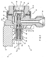
- FIGS 1-3 show an airless spray gun 10 having handle 12, barrel 14, forward housing 14A including fluid inlet passage 20 from a source (not shown) of fluid under pressure and air passage 14B, trigger 16, discharge nozzle 18, and a fluid needle loading assembly 22.
- This assembly 22 is a removable cartridge comprising a housing 23, a valve stem 24, a coupling 25 at the proximal end of valve stem 24 for engaging trigger 16, and a valve seal element 26 for engaging and sealing with valve seat 27.
- the valve seal element 26 is spherical and operable with a conical valve seat 27 as shown; however the valve seal element is not necessarily spherical and may have other shapes.
- the seal element 26 and valve seat 27 may be made of specially selected wear-resistant materials well known in the prior art and replaceable if eventually damaged or worn.
- the valve seat element 27 is secured to an annular holder 28 which is removably coupled to the forward housing 14A by threaded portions 29 and 30 respectively.
- the nozzle 18 can be easily removed and cleaned or replaced by unscrewing union nut 31 whose proximal end 32 threadedly engages forward housing 14A and whose distal end 33 engages shoulder 34 of the nozzle 18.
- the nozzle obviously, can be selected to have wall 35 of varying axial length, aperture diameter and other characteristics, known in the prior art.
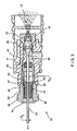
- the removable cartridge or needle valve stem assembly 22 is formed as a cylindrical housing 23 having a proximal part 38 with a first bore diameter D1, a distal part 39 and terminal end 40. Between parts 39 and 40 is a recess 41 formed as a radially outwardly extending annular cavity to receive and hold flexible seal element 42 which has a U-cup cross-section.
- a helical coil spring 45 for urging valve stem 24 in the downstream direction (to the right in Figs. 2 and 3 ), so that its valve seal element 26 tightly engages valve seat 27.
- the spring 45 occupies the cylindrical chamber having diameter D1 and has a distal end 46 that bears against needle shuttle or collar 47 which has an upstream surface 48 against which the spring end 46 bears, urging same in the downstream direction.
- Shuttle 47 has a downstream surface 49 with an inner edge 50 (seen in Fig. 3 ) which will engages the valve stem as explained below.
- Needle valve stem 24 has a proximal part of first diameter D3 and a distal part of larger diameter D4 and has between said proximal and distal parts a transition area formed as a tapered shoulder 52 (marked in Fig. 3 ).
- shuttle 47 has a downstream surface 49 which bears against said shoulder 52.
- Spring 45 applies force in the downstream direction against shuttle 47 whose downstream surface engages and urges shoulder 52, thereby urging the valve stem 24 to the right and thence urges its seal element 26 to seat and seal in valve seat 27.
- proximal end of spring 45 is restrained by end cap 54 which is secured to the proximal end of housing/cartridge 23.
- This cap is preferably pressed and crimped permanently into the proximal end; however, in an alternative construction it could be threadedly engaged.
- a variety of other coupling means could be used to restrain this proximal end of the spring; also other types of springs both internal and external could be used to apply the downstream force on the valve stem.
- the new spray gun of this invention creates a liquid spray in a usual manner, as exemplified by numerous of the prior art references cited above and incorporated herein by reference.
- the novelty in the present invention is the new structure which prevents clogging of relevant parts and permits very swift and easy disassembly, cleaning, repair and re-assembly. Accordingly, the user applies a wrench to nut surface 60 by which the cartridge housing may be threadedly removed. Coupling 25 at the left end of valve stem 24 should be disengaged from the trigger or other actuator that might be used. Then the valve stem 24 can be removed in the downstream direction from the housing 23 and replaced, especially if the seal element 26 is worn or damaged. Also, when the valve stem is removed the seal 42 can be easily replaced.
- Valve seat and annular tip 28 comprise a unit that can be removed and replaced.
- housing 23 is unscrewed with the other aspects of disassembly being optional.
- valve stem can be spring loaded and biased in the downstream direction without the specifically shown transition area or shoulder area between the lead and the tail parts of this stem.
- spring can take various forms and shapes which engage the valve stem.
- the U-cup seal 42 may be replaced by seals of many shapes and materials, including natural and synthetic rubber, plastic and many fiber gasket materials known in this art.
- the seal surface at the terminal end of the valve stem may have spherical, conical, or other shapes, and the material of this surface and of the valve seat will be chosen from many possibilities well known in the art.
- the remaining components of this spray gun are made from metal or plastic and by manufacturing techniques well known in the art.
Landscapes
- Nozzles (AREA)
Applications Claiming Priority (2)
| Application Number | Priority Date | Filing Date | Title |
|---|---|---|---|
| US09/545,818 US6276616B1 (en) | 2000-04-07 | 2000-04-07 | Fluid needle loading assembly for an airless spray paint gun |
| US545818 | 2000-04-07 |
Publications (3)
| Publication Number | Publication Date |
|---|---|
| EP1142645A2 EP1142645A2 (en) | 2001-10-10 |
| EP1142645A3 EP1142645A3 (en) | 2003-03-12 |
| EP1142645B1 true EP1142645B1 (en) | 2009-06-10 |
Family
ID=24177672
Family Applications (1)
| Application Number | Title | Priority Date | Filing Date |
|---|---|---|---|
| EP01104656A Expired - Lifetime EP1142645B1 (en) | 2000-04-07 | 2001-02-24 | Fluid needle loading assembly for an airless spray paint gun |
Country Status (4)
| Country | Link |
|---|---|
| US (1) | US6276616B1 (enExample) |
| EP (1) | EP1142645B1 (enExample) |
| JP (1) | JP2001347199A (enExample) |
| DE (1) | DE60138938D1 (enExample) |
Families Citing this family (54)
| Publication number | Priority date | Publication date | Assignee | Title |
|---|---|---|---|---|
| US20040040988A1 (en) * | 2002-08-30 | 2004-03-04 | Alexander Kevin L. | High pressure ball and valve seat |
| US7472820B2 (en) * | 2002-09-06 | 2009-01-06 | Spx Corporation | Code reading apparatus and method |
| US6838856B2 (en) * | 2002-10-04 | 2005-01-04 | Spx Corporation | Apparatus and method for high-frequency operation in a battery charger |
| US6874708B2 (en) * | 2003-02-13 | 2005-04-05 | Illinois Tool Works Inc. | Automatic air-assisted manifold mounted gun |
| ITRE20030022A1 (it) * | 2003-02-26 | 2004-08-27 | Arrow Line Srl | Valvola di intercettazione particolarmente per pistole |
| US7296760B2 (en) | 2004-11-17 | 2007-11-20 | Illinois Tool Works Inc. | Indexing valve |
| US7296759B2 (en) * | 2004-11-19 | 2007-11-20 | Illinois Tool Works Inc. | Ratcheting retaining ring |
| US20060202060A1 (en) * | 2004-12-06 | 2006-09-14 | Alexander Kevin L | Dispensing device handle assembly |
| US7757973B2 (en) | 2005-04-04 | 2010-07-20 | Illinois Tool Works Inc. | Hand-held coating dispensing device |
| US7460924B2 (en) * | 2005-06-16 | 2008-12-02 | Illinois Tool Works Inc. | In-gun power supply control |
| US7364098B2 (en) * | 2005-10-12 | 2008-04-29 | Illinois Tool Works Inc. | Material dispensing apparatus |
| US7621471B2 (en) * | 2005-12-16 | 2009-11-24 | Illinois Tool Works Inc. | High voltage module with gas dielectric medium or vacuum |
| USD545943S1 (en) | 2006-03-14 | 2007-07-03 | Illinois Tool Works Inc. | Coating material dispensing device |
| US7455249B2 (en) | 2006-03-28 | 2008-11-25 | Illinois Tool Works Inc. | Combined direct and indirect charging system for electrostatically-aided coating system |
| EP1930084B1 (de) | 2006-12-05 | 2009-06-03 | SATA GmbH & Co. KG | Belüftung für den Fließbecher einer Farbspritzpistole |
| US7922107B2 (en) * | 2007-07-25 | 2011-04-12 | Fox Jeffrey D | Spray gun with paint cartridge |
| US8016213B2 (en) * | 2008-03-10 | 2011-09-13 | Illinois Tool Works Inc. | Controlling temperature in air-powered electrostatically aided coating material atomizer |
| US8770496B2 (en) | 2008-03-10 | 2014-07-08 | Finishing Brands Holdings Inc. | Circuit for displaying the relative voltage at the output electrode of an electrostatically aided coating material atomizer |
| US7988075B2 (en) | 2008-03-10 | 2011-08-02 | Illinois Tool Works Inc. | Circuit board configuration for air-powered electrostatically aided coating material atomizer |
| USD608858S1 (en) | 2008-03-10 | 2010-01-26 | Illinois Tool Works Inc. | Coating material dispensing device |
| US7926748B2 (en) * | 2008-03-10 | 2011-04-19 | Illinois Tool Works Inc. | Generator for air-powered electrostatically aided coating dispensing device |
| US8590817B2 (en) * | 2008-03-10 | 2013-11-26 | Illinois Tool Works Inc. | Sealed electrical source for air-powered electrostatic atomizing and dispensing device |
| US8496194B2 (en) | 2008-03-10 | 2013-07-30 | Finishing Brands Holdings Inc. | Method and apparatus for retaining highly torqued fittings in molded resin or polymer housing |
| RU2457041C2 (ru) * | 2008-03-12 | 2012-07-27 | Джеффри Д. ФОКС | Одноразовый картридж для пистолета-краскораспылителя |
| WO2009113980A1 (en) * | 2008-03-12 | 2009-09-17 | Fox Jeffrey D | Disposable spray gun cartridge |
| US7918409B2 (en) * | 2008-04-09 | 2011-04-05 | Illinois Tool Works Inc. | Multiple charging electrode |
| US8899501B2 (en) * | 2008-07-23 | 2014-12-02 | Sata Gmbh & Co. Kg | Spray gun with paint cartridge |
| US8439281B2 (en) * | 2008-08-15 | 2013-05-14 | Hyde Tools, Inc. | Modular coatings sprayer |
| CN103977922B (zh) * | 2008-10-22 | 2017-01-11 | 固瑞克明尼苏达有限公司 | 便携式无空气喷雾器 |
| US8225968B2 (en) | 2009-05-12 | 2012-07-24 | Illinois Tool Works Inc. | Seal system for gear pumps |
| DE102009032399A1 (de) | 2009-07-08 | 2011-01-13 | Sata Gmbh & Co. Kg | Farbspritzpistole |
| RU2012136431A (ru) * | 2010-01-27 | 2014-03-10 | Грако Миннесота Инк. | Безвоздушный распылитель |
| DE202010007355U1 (de) | 2010-05-28 | 2011-10-20 | Sata Gmbh & Co. Kg | Düsenkopf für eine Spritzvorrichtung |
| US8690083B2 (en) * | 2010-10-20 | 2014-04-08 | Finishing Brands Holdings Inc. | Adjustable needle packing assembly for a spray gun |
| US9333519B2 (en) | 2010-12-02 | 2016-05-10 | Sata Gmbh & Co. Kg | Spray gun and accessories |
| EP2726212B2 (de) | 2011-06-30 | 2023-07-12 | SATA GmbH & Co. KG | Leicht zu reinigende spritzpistole, zubehör hierfür, montage- und demontageverfahren |
| JP5619981B2 (ja) * | 2013-10-18 | 2014-11-05 | ジェフリー ディー フォックス | スプレーガン |
| DE202013105779U1 (de) | 2013-12-18 | 2015-03-19 | Sata Gmbh & Co. Kg | Luftdüsenabschluss für eine Lackierpistole |
| US11059062B2 (en) * | 2014-02-19 | 2021-07-13 | Worthen Industries | Airless adhesive spray gun and method of use |
| CN110560285B (zh) | 2014-07-31 | 2021-05-18 | 萨塔有限两合公司 | 喷枪及其制造方法 |
| CA159961S (en) | 2014-07-31 | 2015-07-17 | Sata Gmbh & Co Kg | Spray gun |
| USD768820S1 (en) | 2014-09-03 | 2016-10-11 | Sata Gmbh & Co. Kg | Paint spray gun with pattern |
| US10220404B2 (en) | 2015-02-03 | 2019-03-05 | Worthen Industries | Holster for spray gun |
| DE102015006484A1 (de) | 2015-05-22 | 2016-11-24 | Sata Gmbh & Co. Kg | Düsenanordnung für eine Spritzpistole, insbesondere Farbspritzpistole und Spritzpistole, insbesondere Farbspritzpistole |
| DE102015016474A1 (de) | 2015-12-21 | 2017-06-22 | Sata Gmbh & Co. Kg | Luftkappe und Düsenanordnung für eine Spritzpistole und Spritzpistole |
| CN205995666U (zh) | 2016-08-19 | 2017-03-08 | 萨塔有限两合公司 | 喷枪及其扳机 |
| CN205966208U (zh) | 2016-08-19 | 2017-02-22 | 萨塔有限两合公司 | 风帽组件以及喷枪 |
| KR101829686B1 (ko) | 2017-02-06 | 2018-02-20 | 주식회사 태웅코로죤 | 고압 세척용 분사장치 |
| CN112533705B (zh) | 2018-08-01 | 2023-07-04 | 萨塔有限两合公司 | 喷枪的喷嘴组、喷枪系统、制造喷嘴模块的方法、为上漆任务从喷嘴组选出喷嘴模块的方法、选择系统和计算机程序产品 |
| DE102018118738A1 (de) | 2018-08-01 | 2020-02-06 | Sata Gmbh & Co. Kg | Grundkörper für eine Spritzpistole, Spritzpistolen, Spritzpistolen-Set, Verfahren zur Herstellung eines Grundkörpers für eine Spritzpistole und Verfahren zum Umrüsten einer Spritzpistole |
| DE102018118737A1 (de) | 2018-08-01 | 2020-02-06 | Sata Gmbh & Co. Kg | Düse für eine Spritzpistole, Düsensatz für eine Spritzpistole, Spritzpistolen und Verfahren zur Herstellung einer Düse für eine Spritzpistole |
| US11819870B2 (en) * | 2019-03-01 | 2023-11-21 | William Harrison | System and method for efficient and ergonomic waterproofing of joints and fasteners |
| CN115739435A (zh) | 2019-05-31 | 2023-03-07 | 固瑞克明尼苏达有限公司 | 手持式流体喷雾器 |
| DE102020123769A1 (de) | 2020-09-11 | 2022-03-17 | Sata Gmbh & Co. Kg | Dichtelement zum Abdichten eines Übergangs zwischen einem Grundkörper einer Spritzpistole und einem Anbauteil einer Spritzpistole, Anbauteil, insbesondere Farbdüsenanordnung, für eine Spritzpistole und Spritzpistole, insbesondere Farbspritzpistole |
Family Cites Families (20)
| Publication number | Priority date | Publication date | Assignee | Title |
|---|---|---|---|---|
| US1586009A (en) * | 1923-02-08 | 1926-05-25 | Shelburne Augustine | Air brush |
| GB336173A (en) * | 1929-08-13 | 1930-10-09 | Rene Emile Serpollier | Improvements in apparatus for spraying liquids |
| US1969205A (en) * | 1932-09-06 | 1934-08-07 | Vilbiss Co | Material discharge gun |
| JPS4929727B1 (enExample) * | 1968-01-12 | 1974-08-07 | ||
| US3633828A (en) * | 1970-01-19 | 1972-01-11 | Graco Inc | Spray gun |
| US3767115A (en) | 1971-12-27 | 1973-10-23 | Graco Inc | Electrostatic spray gun apparatus |
| JPS4888589A (enExample) * | 1972-02-03 | 1973-11-20 | ||
| GB2020200B (en) | 1978-03-08 | 1982-09-15 | Air Ind | Electrostatic spraying |
| JPS5595864A (en) * | 1979-01-16 | 1980-07-21 | Mitsubishi Gas Chem Co Inc | Method and device for measurement of dissolved gas density |
| JPS596471A (ja) * | 1982-06-29 | 1984-01-13 | Iwata Tosouki Kogyo Kk | 摺動部の軸封装置 |
| DE3412507A1 (de) | 1984-04-03 | 1985-10-17 | J. Wagner AG, Altstätten | Elektrostatische handspritzpistole |
| US4572438A (en) | 1984-05-14 | 1986-02-25 | Nordson Corporation | Airless spray gun having improved nozzle assembly and electrode circuit connections |
| DE3505618A1 (de) | 1985-02-19 | 1986-08-21 | Kopperschmidt-Mueller Gmbh & Co Kg, 4800 Bielefeld | Verfahren zum beschichten von gegenstaenden mit hilfe eines spruehstrahls und vorrichtung zur durchfuehrung dieses verfahrens |
| JPS63111243A (ja) * | 1986-10-29 | 1988-05-16 | Isuzu Motors Ltd | タ−ビンハウジングの製造方法 |
| JPS6467276A (en) * | 1987-09-05 | 1989-03-13 | Jotaro Goto | Spray gun |
| US5615804A (en) * | 1994-06-23 | 1997-04-01 | Insta-Foam Products, Inc. | Gun for dispensing fluent sealants or the like |
| US5669557A (en) * | 1994-12-14 | 1997-09-23 | Tram-7 Precision, Inc. | System and process for spraying air-dryable liquid materials |
| US5725161A (en) | 1995-02-28 | 1998-03-10 | Nordson Corporation | Electrostatic coating system including improved spray gun for conductive paints |
| US5695120A (en) * | 1995-07-31 | 1997-12-09 | Furon Company | Spray gun |
| US5803372A (en) | 1997-04-03 | 1998-09-08 | Asahi Sunac Corporation | Hand held rotary atomizer spray gun |
-
2000
- 2000-04-07 US US09/545,818 patent/US6276616B1/en not_active Expired - Lifetime
-
2001
- 2001-02-24 DE DE60138938T patent/DE60138938D1/de not_active Expired - Fee Related
- 2001-02-24 EP EP01104656A patent/EP1142645B1/en not_active Expired - Lifetime
- 2001-04-06 JP JP2001108221A patent/JP2001347199A/ja active Pending
Also Published As
| Publication number | Publication date |
|---|---|
| US6276616B1 (en) | 2001-08-21 |
| EP1142645A3 (en) | 2003-03-12 |
| DE60138938D1 (de) | 2009-07-23 |
| EP1142645A2 (en) | 2001-10-10 |
| JP2001347199A (ja) | 2001-12-18 |
Similar Documents
| Publication | Publication Date | Title |
|---|---|---|
| EP1142645B1 (en) | Fluid needle loading assembly for an airless spray paint gun | |
| AU605017B2 (en) | Spray gun | |
| CA2653779C (en) | Fluid atomizing system and method | |
| US4513913A (en) | Reversible airless spray nozzle | |
| AU631329B2 (en) | Paint spray gun | |
| EP1427535B1 (en) | Spray gun | |
| US7926733B2 (en) | Fluid atomizing system and method | |
| EP0513626B1 (en) | Electrostatic high voltage, low pressure paint spray gun | |
| JPH06154660A (ja) | スプレーノズル装置 | |
| CN101242909B (zh) | 用于喷射带颜料的液体的装置 | |
| KR20070083724A (ko) | 인덱싱 밸브 | |
| US5720433A (en) | Draw back valve for a glue gun | |
| US20230087047A1 (en) | Spray gun, in particular a pressurised air atomisation paint spray gun, in particular a hand-held pressurised air atomisation paint spray gun | |
| US4269355A (en) | Self-cleaning spray nozzle | |
| WO2013112669A1 (en) | Multiple discharge pressurized air atomization spraying system | |
| GB2119288A (en) | Air spray gun | |
| CN108014940B (zh) | 气动喷涂组件、限流器以及喷涂装置 | |
| GB2247193A (en) | Control of spreader air in a spraygun | |
| KR100515634B1 (ko) | 분무용량 조절이 가능한 분무기 | |
| HK1119116B (en) | Method for spraying on pigmented liquids | |
| JPH0362470B2 (enExample) | ||
| HK1099531A (en) | Spray gun with adjustable spray pattern |
Legal Events
| Date | Code | Title | Description |
|---|---|---|---|
| PUAI | Public reference made under article 153(3) epc to a published international application that has entered the european phase |
Free format text: ORIGINAL CODE: 0009012 |
|
| AK | Designated contracting states |
Kind code of ref document: A2 Designated state(s): AT BE CH CY DE DK ES FI FR GB GR IE IT LI LU MC NL PT SE TR |
|
| AX | Request for extension of the european patent |
Free format text: AL;LT;LV;MK;RO;SI |
|
| RIC1 | Information provided on ipc code assigned before grant |
Free format text: 7B 05B 1/30 A, 7B 05B 9/01 B |
|
| PUAL | Search report despatched |
Free format text: ORIGINAL CODE: 0009013 |
|
| AK | Designated contracting states |
Kind code of ref document: A3 Designated state(s): AT BE CH CY DE DK ES FI FR GB GR IE IT LI LU MC NL PT SE TR Designated state(s): AT BE CH CY DE DK ES FI FR GB GR IE IT LI LU MC NL PT SE TR |
|
| AX | Request for extension of the european patent |
Extension state: AL LT LV MK RO SI |
|
| 17P | Request for examination filed |
Effective date: 20030221 |
|
| AKX | Designation fees paid |
Designated state(s): DE ES FR GB IT |
|
| 17Q | First examination report despatched |
Effective date: 20050114 |
|
| GRAP | Despatch of communication of intention to grant a patent |
Free format text: ORIGINAL CODE: EPIDOSNIGR1 |
|
| GRAS | Grant fee paid |
Free format text: ORIGINAL CODE: EPIDOSNIGR3 |
|
| GRAA | (expected) grant |
Free format text: ORIGINAL CODE: 0009210 |
|
| AK | Designated contracting states |
Kind code of ref document: B1 Designated state(s): DE ES FR GB IT |
|
| REG | Reference to a national code |
Ref country code: GB Ref legal event code: FG4D |
|
| REF | Corresponds to: |
Ref document number: 60138938 Country of ref document: DE Date of ref document: 20090723 Kind code of ref document: P |
|
| PG25 | Lapsed in a contracting state [announced via postgrant information from national office to epo] |
Ref country code: ES Free format text: LAPSE BECAUSE OF FAILURE TO SUBMIT A TRANSLATION OF THE DESCRIPTION OR TO PAY THE FEE WITHIN THE PRESCRIBED TIME-LIMIT Effective date: 20090921 |
|
| PLBE | No opposition filed within time limit |
Free format text: ORIGINAL CODE: 0009261 |
|
| STAA | Information on the status of an ep patent application or granted ep patent |
Free format text: STATUS: NO OPPOSITION FILED WITHIN TIME LIMIT |
|
| 26N | No opposition filed |
Effective date: 20100311 |
|
| GBPC | Gb: european patent ceased through non-payment of renewal fee |
Effective date: 20100224 |
|
| REG | Reference to a national code |
Ref country code: FR Ref legal event code: ST Effective date: 20101029 |
|
| PG25 | Lapsed in a contracting state [announced via postgrant information from national office to epo] |
Ref country code: FR Free format text: LAPSE BECAUSE OF NON-PAYMENT OF DUE FEES Effective date: 20100301 |
|
| PG25 | Lapsed in a contracting state [announced via postgrant information from national office to epo] |
Ref country code: DE Free format text: LAPSE BECAUSE OF NON-PAYMENT OF DUE FEES Effective date: 20100901 |
|
| PG25 | Lapsed in a contracting state [announced via postgrant information from national office to epo] |
Ref country code: IT Free format text: LAPSE BECAUSE OF FAILURE TO SUBMIT A TRANSLATION OF THE DESCRIPTION OR TO PAY THE FEE WITHIN THE PRESCRIBED TIME-LIMIT Effective date: 20090610 Ref country code: GB Free format text: LAPSE BECAUSE OF NON-PAYMENT OF DUE FEES Effective date: 20100224 |