EP1142522A1 - Flexible element for forming a piece of cutlery - Google Patents
Flexible element for forming a piece of cutlery Download PDFInfo
- Publication number
- EP1142522A1 EP1142522A1 EP00107235A EP00107235A EP1142522A1 EP 1142522 A1 EP1142522 A1 EP 1142522A1 EP 00107235 A EP00107235 A EP 00107235A EP 00107235 A EP00107235 A EP 00107235A EP 1142522 A1 EP1142522 A1 EP 1142522A1
- Authority
- EP
- European Patent Office
- Prior art keywords
- flexible element
- element according
- bent position
- retaining
- bending line
- Prior art date
- Legal status (The legal status is an assumption and is not a legal conclusion. Google has not performed a legal analysis and makes no representation as to the accuracy of the status listed.)
- Withdrawn
Links
- 238000005452 bending Methods 0.000 claims abstract description 64
- 239000000463 material Substances 0.000 claims abstract description 11
- 230000037431 insertion Effects 0.000 claims description 5
- 238000003780 insertion Methods 0.000 claims description 5
- 230000000295 complement effect Effects 0.000 claims description 4
- 229920002994 synthetic fiber Polymers 0.000 claims description 4
- -1 Polypropylene Polymers 0.000 claims description 3
- 239000004743 Polypropylene Substances 0.000 claims description 3
- 230000001154 acute effect Effects 0.000 claims description 3
- 229920001155 polypropylene Polymers 0.000 claims description 3
- 238000006748 scratching Methods 0.000 claims description 3
- 230000002393 scratching effect Effects 0.000 claims description 3
- 235000013618 yogurt Nutrition 0.000 description 13
- 235000013305 food Nutrition 0.000 description 5
- 239000002390 adhesive tape Substances 0.000 description 4
- 238000004806 packaging method and process Methods 0.000 description 3
- 230000000717 retained effect Effects 0.000 description 3
- 238000004519 manufacturing process Methods 0.000 description 2
- 239000004033 plastic Substances 0.000 description 2
- 229920003023 plastic Polymers 0.000 description 2
- 239000004411 aluminium Substances 0.000 description 1
- 229910052782 aluminium Inorganic materials 0.000 description 1
- XAGFODPZIPBFFR-UHFFFAOYSA-N aluminium Chemical compound [Al] XAGFODPZIPBFFR-UHFFFAOYSA-N 0.000 description 1
- 238000001746 injection moulding Methods 0.000 description 1
- 239000002184 metal Substances 0.000 description 1
- 229910052751 metal Inorganic materials 0.000 description 1
- 230000003313 weakening effect Effects 0.000 description 1
Images

Classifications
-
- B—PERFORMING OPERATIONS; TRANSPORTING
- B65—CONVEYING; PACKING; STORING; HANDLING THIN OR FILAMENTARY MATERIAL
- B65D—CONTAINERS FOR STORAGE OR TRANSPORT OF ARTICLES OR MATERIALS, e.g. BAGS, BARRELS, BOTTLES, BOXES, CANS, CARTONS, CRATES, DRUMS, JARS, TANKS, HOPPERS, FORWARDING CONTAINERS; ACCESSORIES, CLOSURES, OR FITTINGS THEREFOR; PACKAGING ELEMENTS; PACKAGES
- B65D77/00—Packages formed by enclosing articles or materials in preformed containers, e.g. boxes, cartons, sacks or bags
- B65D77/22—Details
- B65D77/24—Inserts or accessories added or incorporated during filling of containers
- B65D77/245—Utensils for removing the contents from the package, e.g. spoons, forks, spatulas
-
- A—HUMAN NECESSITIES
- A47—FURNITURE; DOMESTIC ARTICLES OR APPLIANCES; COFFEE MILLS; SPICE MILLS; SUCTION CLEANERS IN GENERAL
- A47G—HOUSEHOLD OR TABLE EQUIPMENT
- A47G21/00—Table-ware
- A47G21/02—Forks; Forks with ejectors; Combined forks and spoons; Salad servers
-
- A—HUMAN NECESSITIES
- A47—FURNITURE; DOMESTIC ARTICLES OR APPLIANCES; COFFEE MILLS; SPICE MILLS; SUCTION CLEANERS IN GENERAL
- A47G—HOUSEHOLD OR TABLE EQUIPMENT
- A47G21/00—Table-ware
- A47G2021/002—Table-ware collapsible
Definitions
- the invention relates to a flexible element for forming a piece of disposable cutlery, especially a spoon.
- Disposable cutlery is e. g. known from European Patent EP 0 725 586 B1.
- the cutlery in the form of a spoon, a fork or a knife is made from thin-walled rigid plastics material and is especially used for catering purposes and with food packaging.
- the known cutlery may be manufactured easily at low costs.
- the invention is based on the idea that disposable cutlery may be formed in a surprisingly easy manner by using a flexible element the body of which is shaped such that in a bent position a handling portion and an acting portion of the piece of cutlery is formed.
- the flexible element comprises an elongated body made from thin, bendable material comprising a handle portion and an acting portion wherein the body widens towards the free end of the acting portion. At least a first bending line extends in the longitudinal direction of the body from the area of the free end of the handle portion towards the acting portion such that the body may be bent and in the bent position the handle has a substantially V- or U-shaped cross section. In its bent position the flexible element is rigid enough to be used as a piece of cutlery, especially a spoon.
- the flexible element according to the invention may be manufactured very easily at very low costs.
- the flexible element may be bundled, packaged and sold with various products so that together with the product always a piece of cutlery is available.
- the flexible element may be bundled, packaged and sold together with a yogurt cup so that for the user there is no longer the need to carry a spoon with him.
- the user may simply separate the flexible element from the yogurt cup, bring the flexible element in its bent position for forming a spoon and may then eat the yogurt. After use the flexible element may be disposed. Of course, it is possible to reuse the flexible element.
- the flexible element according to the invention furthermore may be used for catering purposes in general and food packaging in general.
- the flexible element according to the invention may be stored easily and may be used easily in dispensers. It may be provided on a roll of a plurality of flexible elements, in bulk or separate.
- the flexible element In the unbent position the flexible element may be packaged with small food containers while in its bent position it forms e.g. a normal size spoon.
- the flexible element according to the invention is suitable for forming a spoon, a fork or a knife. However, it is especially suitable for forming a spoon.
- the element forms a knife its body is provided with a serrated edge.
- a second and a third bending line extend from the area of the first bending line towards the free end of the acting portion.
- the additional bending lines make it easier to bend the flexible element, e. g. for forming a spoon.
- the pattern of the bending lines depends on the desired shape of the acting portion, e.g. to form a deep spoon or a shallow spoon.
- the second and third bending lines diverge from each other towards the free end of the acting portion.
- the shape of the acting portion is more similar to the shape of a conventional spoon.
- the second and third bending lines may make an acute angle with the first bending line as provided by a further embodiment.
- the first, second and third bending lines meet at the same point. This embodiment makes it easier to bend the flexible element.
- the first bending line extends towards the free end of the acting portion beyond the point at which the second and third bending lines meet.
- two first bending lines extend substantially in parallel to each other.
- the handle portion of the flexible element in the bent position has a substantially U-shaped cross section.
- the free rim of the acting portion is rounded inwardly or outwardly.
- the shape of the acting portion is even more similar to the shape of the acting portion of a conventional spoon.
- At least one bending line, especially the first bending line is a straight line and/or that at least one bending line, especially the second or third bending line is a curved line.
- the material of the body may be weakened along the bending line or bending lines as it is provided by a further preferred embodiment.
- the material of the body is weakened along the bending line or bending lines by scratching or cutting it on the surface along a continuous line or a series of short consecutive lines or by preforming the bending line or bending lines when manufacturing the body, especially by injection moulding.
- a very simple tool may be used for weakening the material of the body thereby reducing manufacturing costs.
- retaining means for retaining the body in its bent position are provided. In this embodiment it is no longer necessary for the user to retain the flexible element in its bent position by his hand so that handling the flexible element is simplified.
- any suitable retaining means may be provided.
- the retaining means comprises a strip, a ring or a clamp.
- the retaining means may be manufactured easily at low costs.
- the retaining means may be fixed detachably to the body of the flexible element, e.g. by means of a piece of adhesive tape.
- the flexible element When packaged with a food container the flexible element may be received in its unbent position in indent or a cavity of the container's lid or base.
- the retaining means in the bent position of the body the retaining means may be positioned in the area of the acting portion. However, it is preferred that the retaining means is positioned around the handle portion in the bent position of the body.
- the ring is a ring preferrably made from rubber to be pushed over the handle portion in the bent position of the body.
- the retaining means may be handled very easily by the user.
- the body of the flexible element may be made from any suitable material, e. g. from a thin sheet of aluminium. However, it is preferred that the body is made from synthetic material, especially Polypropylene. Synthetic material is available at very low costs and is in the bent position of the flexible element rigid enough to form a piece of cutlery.
- the body is transparent, coloured or translucent.
- the retaining means may be formed by a separate means as mentioned above.
- the retaining means is formed integrally with the body. In this embodiment no separate retaining means is required. Therefore handling the flexible element is simplified for the user. Furthermore, in this embodiment the flexible element may be manufactured even more easily at even lower costs.
- the retaining means comprises a retaining element which in the bent position of the body is held in a force-locking and/or form-fitting manner in a recess or an opening in the body thereby retaining the body in its bent position.
- This embodiment may be manufactured very easily and handled by the user very easily.
- the retaining element comprises a flexible tongue formed integrally with one web of the V-shaped or U-shaped cross-section of the body in its bent position, wherein the tongue comprises at least one lateral projection, wherein the second web of the cross-section comprises a slit or the like and wherein the tongue may be flexed for insertion into the slit in the bent position of the body, such that the tongue flexes back after insertion into the slit thereby engaging the outer wall of the second web with its at least one lateral projection thereby retaining the body in its bent position.
- the retaining element may be handled very easily by the user. In its retaining position the retaining element retains the body safely in its bent position.
- the retaining element comprises at least one projection projecting from the plane of the body in the unbent position of the body wherein in the bent position of the body the projection is held in a force-locking and/or form/fitting manner in a recess or an opening of the body shaped substantially complementary to the projection thereby retaining in its bent position.
- the projection projecting from the plane of the body in the unbent position of the body is formed on a tongue formed integrally with the body.
- the retaining means comprise snapping means for snapping into a recess or an opening in the body in the bent position of the body thereby retaining the body in its bent position.
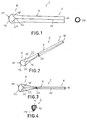
- reference numeral 2 generally designates a flexible element for forming a piece of disposable cutlery, especially a spoon.
- the flexible element comprises a elongated, substantially recangular body 4 made from thin, bendable or flexible synthetic material, e. g. Polypropylene.
- the body 4 comprises a handle portion 6 and an acting portion 8. As can be seen from fig. 1 the body 4 widens towards the free end 10 of the acting portion 8 with the free rim 12 of the acting portion 8 being rounded outwardly.
- a first bending line 14 extends from the free rim 16 of the handle portion 6 towards the acting portion 8 such that the body 4 may be bent and in the bent position the handle portion 6 has a substantially V-shaped cross section as will be explained in more detail below with reference to figures 2 to 4.
- a second bending line 18 and a third bending line 20 extend from the area of the first bending line 14 towards the free end 10 of the acting portion 8 wherein the second and third bending lines 18, 20 diverge from each other towards the free end 10 of the acting portion 8 forming an acute angle with the first bending line 14.
- the first, second and third bending line 14, 18 and 20 meet at the same point 22 and the bending lines 14, 18 and 20 are straight lines.
- the material of the body 4 is weakened by scratching or cutting it on its surface along the bending lines 14, 18, 20.
- the bending lines 14, 18, 20 may be preformed, e.g. when the body 4 is injection-moulded.
- a retaining means for retaining the flexible element 2 in its bent position is shown.
- the retaining means has the form of a small, circular rubber ring 24.
- the user bends body 4 of the flexible element 2 along the bending line 14 such that in the bent position the handle portion 6 has a substantially V-shaped cross section as can be seen from fig. 4. Due to the second and third bending lines 18, 20 in the bent position of the flexible element 2 the acting portion 8 has a shape very similar to the shape of a conventional spoon forming a small depression. In order to retain the body 4 in its bent position the user pushes the small rubber ring 24 over the free end 16 of the handle portion 6 and along the handle portion 6.
- Fig. 2 shows the flexible element 2 in its bent position with the rubber ring 24 in its retaining position. Since the flexible element 2 is retained in its bent position handling of the spoon formed by the flexible element 2 is very easy.
- the flexible element 2 according to the invention provides a piece of cutlery in a very simple manner at very low costs. Due to its flexibility in its unbent position it may be bundled and packaged in various manners with various products. In its bent position the flexible element 2 according to fig. 1 is rigid enough in order to be used in almost all cases in which a conventional metal or plastic spoon could be used.
- Fig. 3 shows a top plan view to the flexible element of fig. 2 in its bent position.
- the rubber ring 24 is sized such that in the bent position of the flexible element 2 it fits tightly around the handle portion 6 thereby retaining the flexible element 2 in a bent position.
- Fig. 5 shows a second embodiment of the flexible element 2 according to the invention which differs from the embodiment of fig. 1 in that the second and third bending lines 18, 20 are curved lines and that the first bending line 14 extends towards the free end 10 of the acting portion 8 beyond the point 26 at which the second and third bending lines 18, 20 meet.
- Fig. 6 shows a third embodiment of the flexible element 2 according to the invention which differs from the embodiment of fig. 5 in that two first bending lines 14' and 14'' are provided wherein first bending line 14' forms a continuous line with third bending line 20 and further first bending line 14'' forms a continuous line with second bending line 18.
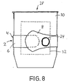
- Fig. 8 shows a side view of a container for receiving food in the form of a disposable yoghurt cup bundled and packaged together with the embodiment of fig. 5.
- the flexible element 2 is positioned around the outer wall 30 of the yoghurt cup 28.
- a piece of adhesive tape 32 is used wherein the rubber ring 24 is positioned between the adhesive tape 32 and the acting portion 8 of the flexible element 2.
- the user may simple tear off the adhesive tape 32, bring the flexible element 2 in its bent position and fix it in its bent position by means of rubber ring 24 as shown in fig. 2. Thereby the user obtains in a very simple manner a spoon for eating the yoghurt so that it is no longer necessary for the user to carry a spoon with him. After use the flexible element 2 may be reused or disposed.
- the flexible element 2 may be received in its unbent position in a cavity of the yoghurt cup 28 e.g. positioned along the inner wall of the yoghurt cup 28 beyond the lid of the yoghurt cup.
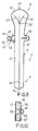
- Fig. 9 shows a forth embodiment of a flexible element according to the invention.
- the retaining means is formed integrally with the first web 33 the body 4 and comprises a tongue 34 which is bendable along a bending line 36 relative to the body 4.
- the tongue 34 comprises a narrowing 38 and two lateral projections 40, 42.
- the other web 35 of the body 4 comprises a slit 44 which is substantially perpendicular to the longitudinal axis of the body 4.
- the slit 44 is sized such that in the bent position of the body 4 the tongue 34 may be flexed by about 90° and inserted into the slit 44.
- the tongue 34 After insertion of the tongue 34 into the slit 44 the tongue 34 flexes back by about 90° such that the narrowing 38 is received in the slit 44 and the lateral projections 40, 42 engage the outer wall 46 of the web 35 as can be seen from fig. 10. Thereby the body 4 is retained in a safe and easy manner in its bent position.
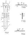
- Fig. 11 shows a fifth embodiment of a flexible element 2 according to the invention.
- the retaining means are formed integrally with the body 4 and comprise a series of projections in the form of circular knubs 48, 50, 52 which are formed on the web 33 and extend from the plane of the body 4 in its unbent position.
- the projections 48, 50, 52 are inserted into and fit into substantially complementary shaped ciruclar openings 54, 56, 58 formed in the web 35.
- Fig. 14 shows an alternative retaining means which is similar to the retaining means of the embodiment of fig. 11.
- the knubs 48, 50, 52 have an undercut 60 such that the knubs 48, 50, 52 snap into the corresponding openings 54, 56, 58 in a pushbutton-like manner such that the retaining means form snapping means.
Landscapes
- Engineering & Computer Science (AREA)
- Mechanical Engineering (AREA)
- Table Equipment (AREA)
Abstract
A flexible element (2) for forming a piece of
disposable cutlery, especially a spoon, comprises an
elongated body (4) made from thin, bendable material
comprising a handle portion (6) and an acting portion
(8), wherein the body (4) widens towards the free end
(10) of the acting portion (8) and wherein at least a
first bending line (14) extends in the longitudinal
direction of the body (4) from the area of the free
end (16) of handle portion (6) towards the acting
portion (8), such that the body (4) may be bent and
in the bent position the handle portion (6) has a
substantially V-shaped or U-shaped cross section. The
flexible element (2) according to the invention may
be manufactured very easily at very low costs. Due to
its flexibility in the unbent position the flexible
element (2) may be bundled, packaged and sold with
various products so that together with the product
always a piece of cutlery is available.
Description
The invention relates to a flexible element for
forming a piece of disposable cutlery, especially a
spoon.
Disposable cutlery is e. g. known from European
Patent EP 0 725 586 B1. The cutlery in the form of a
spoon, a fork or a knife is made from thin-walled
rigid plastics material and is especially used for
catering purposes and with food packaging. The known
cutlery may be manufactured easily at low costs.
It is an object of the present invention to
provide disposable cutlery which may be manufactured
at even lower costs than the known disposable
cutlery.
This object is achieved by the teaching given in
claim 1.
The invention is based on the idea that
disposable cutlery may be formed in a surprisingly
easy manner by using a flexible element the body of
which is shaped such that in a bent position a
handling portion and an acting portion of the piece
of cutlery is formed. According to the invention the
flexible element comprises an elongated body made
from thin, bendable material comprising a handle
portion and an acting portion wherein the body widens
towards the free end of the acting portion. At least
a first bending line extends in the longitudinal
direction of the body from the area of the free end
of the handle portion towards the acting portion such
that the body may be bent and in the bent position
the handle has a substantially V- or U-shaped cross
section. In its bent position the flexible element is
rigid enough to be used as a piece of cutlery,
especially a spoon.
The flexible element according to the invention
may be manufactured very easily at very low costs.
Due to its flexibility in the unbent position
the flexible element may be bundled, packaged and
sold with various products so that together with the
product always a piece of cutlery is available. E. g.
the flexible element may be bundled, packaged and
sold together with a yogurt cup so that for the user
there is no longer the need to carry a spoon with
him. In order to eat the yogurt, the user may simply
separate the flexible element from the yogurt cup,
bring the flexible element in its bent position for
forming a spoon and may then eat the yogurt. After
use the flexible element may be disposed. Of course,
it is possible to reuse the flexible element.
The flexible element according to the invention
furthermore may be used for catering purposes in
general and food packaging in general.
Due to the flatness of its body in the unbent
position the flexible element according to the
invention may be stored easily and may be used easily
in dispensers. It may be provided on a roll of a
plurality of flexible elements, in bulk or separate.
In the unbent position the flexible element may
be packaged with small food containers while in its
bent position it forms e.g. a normal size spoon.
Basically, the flexible element according to the
invention is suitable for forming a spoon, a fork or
a knife. However, it is especially suitable for
forming a spoon. When the element forms a knife its
body is provided with a serrated edge.
Basically, it is sufficient that only one
bending line is provided. However, in a preferred
embodiment in the area of the handle portion a second
and a third bending line extend from the area of the
first bending line towards the free end of the acting
portion. The additional bending lines make it easier
to bend the flexible element, e. g. for forming a
spoon. The pattern of the bending lines depends on
the desired shape of the acting portion, e.g. to form
a deep spoon or a shallow spoon.
According to a further embodiment the second and
third bending lines diverge from each other towards
the free end of the acting portion. In this
embodiment in the bent position the shape of the
acting portion is more similar to the shape of a
conventional spoon.
According to the respective requirements the
second and third bending lines may make an acute
angle with the first bending line as provided by a
further embodiment.
According to another embodiment, the first,
second and third bending lines meet at the same
point. This embodiment makes it easier to bend the
flexible element.
According to yet another embodiment the first
bending line extends towards the free end of the
acting portion beyond the point at which the second
and third bending lines meet.
In a further preferred embodiment two first
bending lines extend substantially in parallel to
each other. In this embodiment in the bent position
the handle portion of the flexible element has a
substantially U-shaped cross section.
In a further preferred embodiment the free rim
of the acting portion is rounded inwardly or
outwardly. When the flexible element forms a spoon in
this embodiment the shape of the acting portion is
even more similar to the shape of the acting portion
of a conventional spoon.
Further preferred embodiments provide that at
least one bending line, especially the first bending
line, is a straight line and/or that at least one
bending line, especially the second or third bending
line is a curved line.
In order to make it easier to bring the flexible
element into its bent position the material of the
body may be weakened along the bending line or
bending lines as it is provided by a further
preferred embodiment.
In the before mentioned embodiment it is
preferred that the material of the body is weakened
along the bending line or bending lines by scratching
or cutting it on the surface along a continuous line
or a series of short consecutive lines or by
preforming the bending line or bending lines when
manufacturing the body, especially by injection
moulding. In this embodiment a very simple tool may
be used for weakening the material of the body
thereby reducing manufacturing costs.
Basically, it is sufficient that the user brings
the flexible element into its bent position and
retains it in the bent position by his hand. However,
in an extraordinarily advantegeous embodiment
retaining means for retaining the body in its bent
position are provided. In this embodiment it is no
longer necessary for the user to retain the flexible
element in its bent position by his hand so that
handling the flexible element is simplified.
For retaining the body in its bent position any
suitable retaining means may be provided. In a
preferred embodiment the retaining means comprises a
strip, a ring or a clamp. In this embodiment the
retaining means may be manufactured easily at low
costs.
For storage purposes or for use in a dispenser
the retaining means may be fixed detachably to the
body of the flexible element, e.g. by means of a
piece of adhesive tape. When packaged with a food
container the flexible element may be received in its
unbent position in indent or a cavity of the
container's lid or base.
Basically, in the bent position of the body the
retaining means may be positioned in the area of the
acting portion. However, it is preferred that the
retaining means is positioned around the handle
portion in the bent position of the body.
In the embodiment with the ring forming the
retaining means it is preferred that the ring is a
ring preferrably made from rubber to be pushed over
the handle portion in the bent position of the body.
In this embodiment, the retaining means may be
handled very easily by the user.
The body of the flexible element may be made
from any suitable material, e. g. from a thin sheet
of aluminium. However, it is preferred that the body
is made from synthetic material, especially
Polypropylene. Synthetic material is available at
very low costs and is in the bent position of the
flexible element rigid enough to form a piece of
cutlery.
According to further embodiments the body is
transparent, coloured or translucent.
Basically, the retaining means may be formed by
a separate means as mentioned above. However, in an
especially preferred embodiment the retaining means
is formed integrally with the body. In this
embodiment no separate retaining means is required.
Therefore handling the flexible element is simplified
for the user. Furthermore, in this embodiment the
flexible element may be manufactured even more easily
at even lower costs.
According to one embodiment the retaining means
comprises a retaining element which in the bent
position of the body is held in a force-locking
and/or form-fitting manner in a recess or an opening
in the body thereby retaining the body in its bent
position. This embodiment may be manufactured very
easily and handled by the user very easily.
According to a further embodiment the retaining
element comprises a flexible tongue formed integrally
with one web of the V-shaped or U-shaped cross-section
of the body in its bent position, wherein the
tongue comprises at least one lateral projection,
wherein the second web of the cross-section comprises
a slit or the like and wherein the tongue may be
flexed for insertion into the slit in the bent
position of the body, such that the tongue flexes
back after insertion into the slit thereby engaging
the outer wall of the second web with its at least
one lateral projection thereby retaining the body in
its bent position. In this embodiment the retaining
element may be handled very easily by the user. In
its retaining position the retaining element retains
the body safely in its bent position.
According to another embodiment the retaining
element comprises at least one projection projecting
from the plane of the body in the unbent position of
the body wherein in the bent position of the body the
projection is held in a force-locking and/or
form/fitting manner in a recess or an opening of the
body shaped substantially complementary to the
projection thereby retaining in its bent position.
According to yet a further embodiment the
projection projecting from the plane of the body in
the unbent position of the body is formed on a tongue
formed integrally with the body.
According to yet a further embodiment the
retaining means comprise snapping means for snapping
into a recess or an opening in the body in the bent
position of the body thereby retaining the body in
its bent position.
The invention is described in more detail below
in relation to embodiments shown in the attached
drawings in which
- Fig. 1
- shows a schematic top plan view to a first embodiment of a flexible element according to the invention in its unbent position together with a retaining means in form of a small circular rubber ring,
- Fig. 2
- shows a schematic perspective view of the embodiment of fig. 1 in its bent position in a smaller scale than figure 1,
- Fig. 3
- shows a schematic top plan view to the embodiment of fig. 1 in its bent position in a smaller scale than fig. 1,
- Fig. 4
- shows the cross section of the handle portion of the embodiment of fig. 1 in its bent position,
- Fig. 5
- shows a schematic top plan view to a second embodiment of a flexible element according to the invention in its unbent position,
- Fig. 6
- shows a schematic top plan view to a third embodiment of a flexible element according to the invention in its unbent position,
- Fig. 7
- shows a cross-section of the handle portion of the embodiment of fig. 6 in its bent position,
- Fig. 8
- shows a side view of a yogurt cup bundled and packaged with the embodiment of fig. 5,
- Fig. 9
- shows a top plan view to a fourth embodiment of a flexible element according to the invention in its unbent position,
- Fig. 10
- shows a partial top plan view to the embodiment of fig. 9 in its bent position,
- Fig. 11
- shows a fifth embodiment of a flexible element according to the invention in its unbent position,
- Fig. 12
- shows a section along a line A-A- in fig. 11,
- Fig. 13
- shows a section of the handle portion of the embodiment of fig. 11 in its bent position and
- Fig. 14
- shows a sectional view of an alternative retaining means similar to the retaining means of the embodiment of fig. 11.
In the drawings reference numeral 2 generally
designates a flexible element for forming a piece of
disposable cutlery, especially a spoon. The flexible
element comprises a elongated, substantially
recangular body 4 made from thin, bendable or
flexible synthetic material, e. g. Polypropylene. The
body 4 comprises a handle portion 6 and an acting
portion 8. As can be seen from fig. 1 the body 4
widens towards the free end 10 of the acting portion
8 with the free rim 12 of the acting portion 8 being
rounded outwardly.
In the embodiment of fig. 1 a first bending line
14 extends from the free rim 16 of the handle portion
6 towards the acting portion 8 such that the body 4
may be bent and in the bent position the handle
portion 6 has a substantially V-shaped cross section
as will be explained in more detail below with
reference to figures 2 to 4.
In the area of the acting portion 8 a second
bending line 18 and a third bending line 20 extend
from the area of the first bending line 14 towards
the free end 10 of the acting portion 8 wherein the
second and third bending lines 18, 20 diverge from
each other towards the free end 10 of the acting
portion 8 forming an acute angle with the first
bending line 14. In the embodiment of fig. 1 the
first, second and third bending line 14, 18 and 20
meet at the same point 22 and the bending lines 14,
18 and 20 are straight lines. In order to make it
easier for the user to bend the body 4 the material
of the body 4 is weakened by scratching or cutting it
on its surface along the bending lines 14, 18, 20. As
an alternative, the bending lines 14, 18, 20 may be
preformed, e.g. when the body 4 is injection-moulded.
In fig. 1 on the left a retaining means for
retaining the flexible element 2 in its bent position
is shown. The retaining means has the form of a
small, circular rubber ring 24.
In order to bring the flexible element in its
bent position for forming a spoon, the user bends
body 4 of the flexible element 2 along the bending
line 14 such that in the bent position the handle
portion 6 has a substantially V-shaped cross section
as can be seen from fig. 4. Due to the second and
third bending lines 18, 20 in the bent position of
the flexible element 2 the acting portion 8 has a
shape very similar to the shape of a conventional
spoon forming a small depression. In order to retain
the body 4 in its bent position the user pushes the
small rubber ring 24 over the free end 16 of the
handle portion 6 and along the handle portion 6.
Fig. 2 shows the flexible element 2 in its bent
position with the rubber ring 24 in its retaining
position. Since the flexible element 2 is retained in
its bent position handling of the spoon formed by the
flexible element 2 is very easy.
In result the flexible element 2 according to
the invention provides a piece of cutlery in a very
simple manner at very low costs. Due to its
flexibility in its unbent position it may be bundled
and packaged in various manners with various
products. In its bent position the flexible element 2
according to fig. 1 is rigid enough in order to be
used in almost all cases in which a conventional
metal or plastic spoon could be used.
Fig. 3 shows a top plan view to the flexible
element of fig. 2 in its bent position.
As can be seen from fig. 4 the rubber ring 24 is
sized such that in the bent position of the flexible
element 2 it fits tightly around the handle portion 6
thereby retaining the flexible element 2 in a bent
position.
Fig. 5 shows a second embodiment of the flexible
element 2 according to the invention which differs
from the embodiment of fig. 1 in that the second and
third bending lines 18, 20 are curved lines and that
the first bending line 14 extends towards the free
end 10 of the acting portion 8 beyond the point 26 at
which the second and third bending lines 18, 20 meet.
Fig. 6 shows a third embodiment of the flexible
element 2 according to the invention which differs
from the embodiment of fig. 5 in that two first
bending lines 14' and 14'' are provided wherein first
bending line 14' forms a continuous line with third
bending line 20 and further first bending line 14''
forms a continuous line with second bending line 18.
As can be taken from fig. 7 in its bent position
the body 4 is bent along bending lines 14', 14'' such
that handle portion 6 has a substantially U-shaped
cross section wherein body 4 is retained in its bent
position by rubber ring 24.
Fig. 8 shows a side view of a container for
receiving food in the form of a disposable yoghurt
cup bundled and packaged together with the embodiment
of fig. 5. For packaging the flexible element 2
together with the yoghurt cup 28 the flexible element
2 is positioned around the outer wall 30 of the
yoghurt cup 28. In order to fix the flexible element
2 on the outer wall 30 a piece of adhesive tape 32 is
used wherein the rubber ring 24 is positioned between
the adhesive tape 32 and the acting portion 8 of the
flexible element 2.
In order to eat the yoghurt the user may simple
tear off the adhesive tape 32, bring the flexible
element 2 in its bent position and fix it in its bent
position by means of rubber ring 24 as shown in fig.
2. Thereby the user obtains in a very simple manner a
spoon for eating the yoghurt so that it is no longer
necessary for the user to carry a spoon with him.
After use the flexible element 2 may be reused or
disposed.
As an alternative, the flexible element 2 may be
received in its unbent position in a cavity of the
yoghurt cup 28 e.g. positioned along the inner wall
of the yoghurt cup 28 beyond the lid of the yoghurt
cup.
Fig. 9 shows a forth embodiment of a flexible
element according to the invention. In this
embodiment the retaining means is formed integrally
with the first web 33 the body 4 and comprises a
tongue 34 which is bendable along a bending line 36
relative to the body 4. The tongue 34 comprises a
narrowing 38 and two lateral projections 40, 42.
Opposite to the tongue 34 the other web 35 of the
body 4 comprises a slit 44 which is substantially
perpendicular to the longitudinal axis of the body 4.
The slit 44 is sized such that in the bent position
of the body 4 the tongue 34 may be flexed by about
90° and inserted into the slit 44. After insertion of
the tongue 34 into the slit 44 the tongue 34 flexes
back by about 90° such that the narrowing 38 is
received in the slit 44 and the lateral projections
40, 42 engage the outer wall 46 of the web 35 as can
be seen from fig. 10. Thereby the body 4 is retained
in a safe and easy manner in its bent position.
Fig. 11 shows a fifth embodiment of a flexible
element 2 according to the invention. In this
embodiment the retaining means are formed integrally
with the body 4 and comprise a series of projections
in the form of circular knubs 48, 50, 52 which are
formed on the web 33 and extend from the plane of the
body 4 in its unbent position.
In the bent position of the body the projections
48, 50, 52 are inserted into and fit into
substantially complementary shaped ciruclar openings
54, 56, 58 formed in the web 35.
From fig. 12 which shows a section along a line
A-A in fig. 11 it can be seen that the projection 52
is shaped substantially complementary to the opening
58. In the bent position of the body 4 the projection
52 fits closely into the opening 58 as can be seen
from fig. 13 thereby retaining the body 4 safely in
its bent position.
Fig. 14 shows an alternative retaining means
which is similar to the retaining means of the
embodiment of fig. 11. In this embodiment the knubs
48, 50, 52, have an undercut 60 such that the knubs
48, 50, 52 snap into the corresponding openings 54,
56, 58 in a pushbutton-like manner such that the
retaining means form snapping means.
Claims (24)
- Flexible element (2) for forming a piece of disposable cutlery, especially a spoon,comprising an elongated body (4) made from thin, bendable material comprising a handle portion (6) and an acting portion (8),wherein the body (4) widens towards the free end (10) of the acting portion (8) andwherein at least a first bending line (14) extends in the longitudinal direction of the body (4) from the area of the free end (16) of the handle portion (6) towards the acting portion (8), such that the body (4) may be bent and in the bent position the handle portion (6) has a substantially V-shaped or U-shaped cross section.
- Flexible element according to claim 1, characterised in that in the area of the acting portion (8) a second (18) and a third bending line (20) extend from the area of the first bending line (14) towards the free end (10) of the acting portion (8).
- Flexible element according to claim 2, characterised in that the second and third bending lines (18, 20) diverge from each other towards the free end (10) of the acting portion (8).
- Flexible element according to claim 2, characterised in that the second and third bending lines (18, 20) make an acute angle with the first bending line.
- Flexible element according to claim 2, characterised in that the first, second and third bending lines (14, 18, 20) meet at the same point (22).
- Flexible element according to claim 2, characterised in that the first bending line (14) extends towards the free end (10) of the acting portion (8) beyond a point (26) at which the second and third bending lines (18, 20) meet.
- Flexible element according to claim 1, characterised in that two first bending lines (14', 14'') extend substantially in parallel to each other.
- Flexible element according to claim 1, characterised in that the free rim (12) of the acting portion (8) is rounded inwardly or outwardly.
- Flexible element according to claim 1 or 2, characterised in that at least one bending line, especially the first bending line (14), is a straight line.
- Flexible element according to claim 1 or 2,
characterised in that at least one bending line, especially the second or third bending line (18, 20) is a curved line. - Flexible element according to claim 1 or 2, characterised in that the material of the body (4) is weakened along the bending line or bending lines (14, 18, 20).
- Flexible element according to claim 11, characterised in that the material of the body is weakened along the bending line or bending lines (12, 14, 18) by scratching or cutting it on the surface along a continuous line or a series of short consecutive lines.
- Flexible element according to claim 1, characterised by retaining means for retaining the body (4) in its bent position.
- Flexible element according to claim 13, characterised in that the retaining means comprises a strip, a ring or a clamp.
- Flexible element according to claim 13, characterised in that the retaining means is positioned around the handle portion (6) in the bent position of the body (4).
- Flexible element according to claim 14, characterised in that the ring is a ring (24) preferrably made from rubber to be pushed over the handle portion (6) in the bent position of the body (4).
- Flexible element according to claim 1, characterised in that the body (4) is made from synthetic material, especially Polypropylene.
- Flexible element according to claim 1 characterised in that the body (4) is transparent, coloured or translucent.
- Flexible element according to claim 13 characterised in that the retaining means is formed integrally with the body (4).
- Flexible element according to claim 19 characterised in that the retaining means comprises a retaining element which in the bent position of the body (4) is held in a force-locking and/or form-fitting manner in a recess or an opening (44) in the body (4) thereby retaining the body (4) in its bent position.
- Flexible element according to claim 20 characterized in that the retaining element comprises a flexible tongue (34) formed integrally with one web of the V-shaped or U-shaped cross-section of the body (4) in its bent position,wherein the tongue (34) comprises a least one lateral projection (40, 42), wherein the other web of the cross-section comprises a slit (44) or the like,wherein the tongue (34) may be flexed for insertion into the slit in the bent position of the body, such that the tongue flexes back after insertion into the slit (44) thereby engaging the outer wall of the second web with its a least one lateral projection (40, 42) thereby retaining the body (4) in its bent position.
- Flexible element according to claim 20 characterised in that the retaining element comprises at least one projection (48, 50, 52) projecting from the plane of the body (4) in the unbent position of the body (4), wherein in the bent position of the body (4) the projection (48, 50, 52) is held in a force-locking and/or form-fitting manner in a recess or an opening (54, 56, 58) of the body (4) shaped substantially complementary to the projection (48, 50, 52), thereby retaining the body (4) in its bent position.
- Flexible element according to claim 22 characterised in that the projection (48, 50, 52) projecting from the plane of the body (4) in the unbent position of the body (4) is formed on a tongue formed integrally with the body (4).
- Flexible element according to claim 13 characterised in that the retaining means comprise snapping means for snapping into a recess or an opening in the body in the bent position of the body thereby retaining the body in its bent position.
Priority Applications (1)
| Application Number | Priority Date | Filing Date | Title |
|---|---|---|---|
| EP00107235A EP1142522A1 (en) | 2000-04-03 | 2000-04-03 | Flexible element for forming a piece of cutlery |
Applications Claiming Priority (1)
| Application Number | Priority Date | Filing Date | Title |
|---|---|---|---|
| EP00107235A EP1142522A1 (en) | 2000-04-03 | 2000-04-03 | Flexible element for forming a piece of cutlery |
Publications (1)
| Publication Number | Publication Date |
|---|---|
| EP1142522A1 true EP1142522A1 (en) | 2001-10-10 |
Family
ID=8168364
Family Applications (1)
| Application Number | Title | Priority Date | Filing Date |
|---|---|---|---|
| EP00107235A Withdrawn EP1142522A1 (en) | 2000-04-03 | 2000-04-03 | Flexible element for forming a piece of cutlery |
Country Status (1)
| Country | Link |
|---|---|
| EP (1) | EP1142522A1 (en) |
Cited By (11)
| Publication number | Priority date | Publication date | Assignee | Title |
|---|---|---|---|---|
| WO2007048055A3 (en) * | 2005-10-19 | 2007-11-08 | Francis Bartow Fite Iv | Foldable utensil set |
| EP2591708A1 (en) * | 2011-11-08 | 2013-05-15 | Magisso OY | Scoop used in cooking and/or portioning food |
| US20140069933A1 (en) * | 2012-09-11 | 2014-03-13 | Ecotensil Inc. | Patterning for constructable utensil |
| FR2997895A1 (en) * | 2012-11-14 | 2014-05-16 | Christophe Vinot | THE SPOON FEATHER |
| EP2754372A1 (en) | 2013-01-10 | 2014-07-16 | Magisso OY | Scoop used in cooking and/or portioning food |
| WO2014111631A1 (en) * | 2013-01-21 | 2014-07-24 | Vinot Christophe | Spoon drop |
| US20140259685A1 (en) * | 2013-03-15 | 2014-09-18 | Ecotensil Inc. | Constructible utensils |
| WO2016171761A1 (en) * | 2015-04-22 | 2016-10-27 | Theo Stewart-Stand | Multipurpose eating utensil |
| EP3750456A1 (en) | 2019-06-14 | 2020-12-16 | Formpac i Sverige AB | Flexible element for forming a piece of disposable cutlery |
| US20220225807A1 (en) * | 2011-01-25 | 2022-07-21 | Ecotensil Inc. | Constructible utensils with locking tab |
| US12446717B2 (en) | 2011-01-25 | 2025-10-21 | Ecotensil Inc. | Utensils having inwardly curving and perpendicular scores |
Citations (7)
| Publication number | Priority date | Publication date | Assignee | Title |
|---|---|---|---|---|
| US1521768A (en) * | 1923-03-06 | 1925-01-06 | Mono Service Company | Paper spoon |
| US2375266A (en) * | 1943-09-07 | 1945-05-08 | Richard W Wilson | Combined spoon and lid for containers |
| US3828999A (en) * | 1972-10-24 | 1974-08-13 | D Humphrey | Package including disposable utensil |
| GB2052246A (en) * | 1979-06-12 | 1981-01-28 | Clark W | Spoons, spatulas, pourers etc. |
| EP0338146A1 (en) * | 1988-04-18 | 1989-10-25 | Mitsubishi Shoji Plastics Corporation | Foldable device for handling food |
| US5419049A (en) * | 1992-03-16 | 1995-05-30 | Macarthur-Onslow; Rohan J. | Foldable eating utensil |
| EP0725586A1 (en) | 1993-10-29 | 1996-08-14 | De Ster N.V. | Bundle of items of disposable cutlery |
-
2000
- 2000-04-03 EP EP00107235A patent/EP1142522A1/en not_active Withdrawn
Patent Citations (7)
| Publication number | Priority date | Publication date | Assignee | Title |
|---|---|---|---|---|
| US1521768A (en) * | 1923-03-06 | 1925-01-06 | Mono Service Company | Paper spoon |
| US2375266A (en) * | 1943-09-07 | 1945-05-08 | Richard W Wilson | Combined spoon and lid for containers |
| US3828999A (en) * | 1972-10-24 | 1974-08-13 | D Humphrey | Package including disposable utensil |
| GB2052246A (en) * | 1979-06-12 | 1981-01-28 | Clark W | Spoons, spatulas, pourers etc. |
| EP0338146A1 (en) * | 1988-04-18 | 1989-10-25 | Mitsubishi Shoji Plastics Corporation | Foldable device for handling food |
| US5419049A (en) * | 1992-03-16 | 1995-05-30 | Macarthur-Onslow; Rohan J. | Foldable eating utensil |
| EP0725586A1 (en) | 1993-10-29 | 1996-08-14 | De Ster N.V. | Bundle of items of disposable cutlery |
Cited By (16)
| Publication number | Priority date | Publication date | Assignee | Title |
|---|---|---|---|---|
| WO2007048055A3 (en) * | 2005-10-19 | 2007-11-08 | Francis Bartow Fite Iv | Foldable utensil set |
| US20220225807A1 (en) * | 2011-01-25 | 2022-07-21 | Ecotensil Inc. | Constructible utensils with locking tab |
| US12484725B2 (en) * | 2011-01-25 | 2025-12-02 | Ecotensil Inc. | Constructible utensils with locking tab |
| US12446717B2 (en) | 2011-01-25 | 2025-10-21 | Ecotensil Inc. | Utensils having inwardly curving and perpendicular scores |
| EP2591708A1 (en) * | 2011-11-08 | 2013-05-15 | Magisso OY | Scoop used in cooking and/or portioning food |
| US20140069933A1 (en) * | 2012-09-11 | 2014-03-13 | Ecotensil Inc. | Patterning for constructable utensil |
| US9131793B2 (en) * | 2012-09-11 | 2015-09-15 | Ecotensil Inc. | Patterning for constructable utensil |
| FR2997895A1 (en) * | 2012-11-14 | 2014-05-16 | Christophe Vinot | THE SPOON FEATHER |
| EP2754372A1 (en) | 2013-01-10 | 2014-07-16 | Magisso OY | Scoop used in cooking and/or portioning food |
| US9301631B2 (en) | 2013-01-10 | 2016-04-05 | Magisso Oy | Scoop used in cooking and/or portioning food |
| WO2014111631A1 (en) * | 2013-01-21 | 2014-07-24 | Vinot Christophe | Spoon drop |
| US20140259685A1 (en) * | 2013-03-15 | 2014-09-18 | Ecotensil Inc. | Constructible utensils |
| WO2016171761A1 (en) * | 2015-04-22 | 2016-10-27 | Theo Stewart-Stand | Multipurpose eating utensil |
| EP3750456A1 (en) | 2019-06-14 | 2020-12-16 | Formpac i Sverige AB | Flexible element for forming a piece of disposable cutlery |
| EP3750456B1 (en) | 2019-06-14 | 2021-03-31 | Formpac i Sverige AB | Flexible element for forming a piece of disposable cutlery |
| US12059087B2 (en) | 2019-06-14 | 2024-08-13 | Sky-Light A/S | Flexible element for forming a piece of disposable cutlery |
Similar Documents
| Publication | Publication Date | Title |
|---|---|---|
| US5857615A (en) | Container holder | |
| EP3750456B1 (en) | Flexible element for forming a piece of disposable cutlery | |
| US9474399B2 (en) | Constructible eating utensil with scoop from foldable blank | |
| KR20140103336A (en) | Packaged oral care implement | |
| JP2012530558A (en) | Clip spoon | |
| WO2000023349A1 (en) | Toothbrush display and storage package | |
| US5855215A (en) | Toothpicks and toothpick frame | |
| WO2000047488A1 (en) | Portable food container cover with detachable utensil | |
| EP0338146A1 (en) | Foldable device for handling food | |
| EP2203722B1 (en) | Integrally formed receptacle with depth marks on the sidewall | |
| US8579185B2 (en) | Rounded packaging for comestibles | |
| EP2286667A2 (en) | Disposable container and carrier for a disposable container | |
| EP2925623B1 (en) | Unitary flexible package | |
| KR200336103Y1 (en) | Cake plate | |
| RU39089U1 (en) | CAPACITY FOR GOODS (OPTIONS) | |
| US4453657A (en) | Dispensing package for rolled sheet material | |
| JP7497039B2 (en) | Food Containers | |
| JP7506722B2 (en) | spoon | |
| JPH0636464U (en) | Folding spoon structure | |
| JPH08309042A (en) | Server knife for knife | |
| GB2315255A (en) | Sealed containers incorporating an eating utensil | |
| KR200179866Y1 (en) | paper cup accompannied with straw | |
| GB2379597A (en) | A removable barrier for retaining food on a plate | |
| GB2383259A (en) | A hand guard for carrying a container with a handle | |
| KR100332437B1 (en) | The structure of a square paper-cup |
Legal Events
| Date | Code | Title | Description |
|---|---|---|---|
| PUAI | Public reference made under article 153(3) epc to a published international application that has entered the european phase |
Free format text: ORIGINAL CODE: 0009012 |
|
| AK | Designated contracting states |
Kind code of ref document: A1 Designated state(s): AT BE CH CY DE DK ES FI FR GB GR IE IT LI LU MC NL PT SE |
|
| AX | Request for extension of the european patent |
Free format text: AL;LT;LV;MK;RO;SI |
|
| AKX | Designation fees paid | ||
| REG | Reference to a national code |
Ref country code: DE Ref legal event code: 8566 |
|
| STAA | Information on the status of an ep patent application or granted ep patent |
Free format text: STATUS: THE APPLICATION IS DEEMED TO BE WITHDRAWN |
|
| 18D | Application deemed to be withdrawn |
Effective date: 20020411 |