EP1141599B1 - An apparatus and method for verifying the material properties of a plug valve sealing element - Google Patents
An apparatus and method for verifying the material properties of a plug valve sealing element Download PDFInfo
- Publication number
- EP1141599B1 EP1141599B1 EP00982670A EP00982670A EP1141599B1 EP 1141599 B1 EP1141599 B1 EP 1141599B1 EP 00982670 A EP00982670 A EP 00982670A EP 00982670 A EP00982670 A EP 00982670A EP 1141599 B1 EP1141599 B1 EP 1141599B1
- Authority
- EP
- European Patent Office
- Prior art keywords
- seal
- slip
- adhesive
- recess
- plug
- Prior art date
- Legal status (The legal status is an assumption and is not a legal conclusion. Google has not performed a legal analysis and makes no representation as to the accuracy of the status listed.)
- Expired - Lifetime
Links
Images

Classifications
-
- F—MECHANICAL ENGINEERING; LIGHTING; HEATING; WEAPONS; BLASTING
- F16—ENGINEERING ELEMENTS AND UNITS; GENERAL MEASURES FOR PRODUCING AND MAINTAINING EFFECTIVE FUNCTIONING OF MACHINES OR INSTALLATIONS; THERMAL INSULATION IN GENERAL
- F16K—VALVES; TAPS; COCKS; ACTUATING-FLOATS; DEVICES FOR VENTING OR AERATING
- F16K5/00—Plug valves; Taps or cocks comprising only cut-off apparatus having at least one of the sealing faces shaped as a more or less complete surface of a solid of revolution, the opening and closing movement being predominantly rotary
- F16K5/02—Plug valves; Taps or cocks comprising only cut-off apparatus having at least one of the sealing faces shaped as a more or less complete surface of a solid of revolution, the opening and closing movement being predominantly rotary with plugs having conical surfaces; Packings therefor
- F16K5/0257—Packings
- F16K5/0278—Packings on the plug
-
- F—MECHANICAL ENGINEERING; LIGHTING; HEATING; WEAPONS; BLASTING
- F16—ENGINEERING ELEMENTS AND UNITS; GENERAL MEASURES FOR PRODUCING AND MAINTAINING EFFECTIVE FUNCTIONING OF MACHINES OR INSTALLATIONS; THERMAL INSULATION IN GENERAL
- F16K—VALVES; TAPS; COCKS; ACTUATING-FLOATS; DEVICES FOR VENTING OR AERATING
- F16K5/00—Plug valves; Taps or cocks comprising only cut-off apparatus having at least one of the sealing faces shaped as a more or less complete surface of a solid of revolution, the opening and closing movement being predominantly rotary
- F16K5/04—Plug valves; Taps or cocks comprising only cut-off apparatus having at least one of the sealing faces shaped as a more or less complete surface of a solid of revolution, the opening and closing movement being predominantly rotary with plugs having cylindrical surfaces; Packings therefor
- F16K5/0457—Packings
- F16K5/0478—Packings on the plug
-
- F—MECHANICAL ENGINEERING; LIGHTING; HEATING; WEAPONS; BLASTING
- F16—ENGINEERING ELEMENTS AND UNITS; GENERAL MEASURES FOR PRODUCING AND MAINTAINING EFFECTIVE FUNCTIONING OF MACHINES OR INSTALLATIONS; THERMAL INSULATION IN GENERAL
- F16K—VALVES; TAPS; COCKS; ACTUATING-FLOATS; DEVICES FOR VENTING OR AERATING
- F16K5/00—Plug valves; Taps or cocks comprising only cut-off apparatus having at least one of the sealing faces shaped as a more or less complete surface of a solid of revolution, the opening and closing movement being predominantly rotary
- F16K5/06—Plug valves; Taps or cocks comprising only cut-off apparatus having at least one of the sealing faces shaped as a more or less complete surface of a solid of revolution, the opening and closing movement being predominantly rotary with plugs having spherical surfaces; Packings therefor
- F16K5/0663—Packings
- F16K5/0684—Packings on the plug
-
- G—PHYSICS
- G01—MEASURING; TESTING
- G01N—INVESTIGATING OR ANALYSING MATERIALS BY DETERMINING THEIR CHEMICAL OR PHYSICAL PROPERTIES
- G01N2203/00—Investigating strength properties of solid materials by application of mechanical stress
- G01N2203/02—Details not specific for a particular testing method
- G01N2203/022—Environment of the test
- G01N2203/0244—Tests performed "in situ" or after "in situ" use
-
- G—PHYSICS
- G01—MEASURING; TESTING
- G01N—INVESTIGATING OR ANALYSING MATERIALS BY DETERMINING THEIR CHEMICAL OR PHYSICAL PROPERTIES
- G01N2203/00—Investigating strength properties of solid materials by application of mechanical stress
- G01N2203/02—Details not specific for a particular testing method
- G01N2203/06—Indicating or recording means; Sensing means
- G01N2203/0664—Indicating or recording means; Sensing means using witness specimens
Definitions
- the present invention relates generally to the field of plug valves used to control the flow of fluids, and more specifically to an apparatus for verifying the material properties of a sealing element used in non-lubricated, double block and bleed plug valves.
- plug-type valves are implemented with slips and seals in a seat and reseat configuration.
- the slips and seals provide means for blocking the flow through the valve at both the inlet and outlet ports when the valve is in the closed position. This permits maintenance personnel to bleed the valve body with the valve in its closed position with a minimum expenditure of time and labor costs.
- the plug slips are interconnected so that in opening the valve from its fully closed position, (beginning with the valve in the seated/closed position) the first motion of the plug is upward vertical in one direction which has the effect of retracting the slips from the inside surface of the valve body in order to prevent scoring of the valve seals in the subsequent motion when the valve is turned to place the flow passage to be in line with the inlet and outlet.
- Heat, time, temperature and energy, pressure and elastomer formulation directly affect the material properties of the seals of valves. Also cleanliness, surface preparation and profile affect the bond of the seal to the substrate. Further, chemical age, moisture content and sand blast affect the quality of the bond strength of valve seals to valve slips.
- Seal quality needs to be verified in some manner.
- Various test coupons are used for chemical and physical verification of steel. Much like such steel properties verification, there is a need to develop seal properties verification techniques.
- test coupon or sample in a separate specimen would work to some degree, but one cannot be sure that it was processed equally with the production batch. This is the present state of the art, namely, manufacture another slip and then pull test that slip's seal.
- the present invention relates to a unique way to test a plug valve seal by embedding a test coupon into the face of the slip. By doing so, all variables are controlled. Even the heat energy is averaged by placing the test coupon at the mid-section of the slip.
- the elastomer prepared for the seal groove is identical and is prepared in the same batch as that for the test coupon and all installed with the same tackifying agent by the same individual.
- the pressure and an upper platen heat travel through the thick and thin ends of the slip to the groove side of the seal causing the bonding and curing process to proceed.
- the test coupon placed at the mid-section sees the representative average heat energy. Meanwhile, the lower platen transfers its heat energy via a pre-heated mold to the seal material causing equal curing across the entire seal and test coupon boss.
- the seal cross-section is the same as the test section of the seal test coupon.
- the flash is removed simultaneously.
- the post cure is next completed equally on seal and test coupon.
- the test coupon test tab (which was prevented from adhering mechanically or chemically earlier) is released and placed into a pull tab fixture and a varying known load is applied.
- the elongation is monitored and a stress/strain curve can be generated, verifying material properties. Further pulled to failure, the seal groove adhesion is verified.
- the removed test tab can then be compression set tested and a variety of other tests can be performed. Material and performance certifications can be generated for each slip seal.
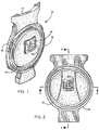
- a valve slip 10 in accordance with a preferred embodiment of the present invention, comprises a slip body 16 having a sealing face 12 and a plug interface 14.
- Sealing face 12 comprises a seal 18 of generally circular shape which extends around the entire face 12 near its perimeter.
- Plug interface 14 has a dove tail cross-section which mates with a complimentary interface on the plug (not shown) permitting vertical translation of the slip relative to the plug in the manner described above in regard to the prior art.
- test coupon 20 which is preferably located on a central platform 19 on sealing face 12.
- test coupon 20 has a base portion 23 adhesively positioned in a recess 24.
- Recess 24 is substantially identical in cross-sectional dimensions to the recess 22 in which seal 18 is adhesively secured.
- the test coupon 20 and seal 18 are preferably made from the same batch of material at the same time and adhesively secured in their respective recesses 22 and 24 using the same adhesive and curing time and temperature.
- the remainder of test coupon 20, namely, tab 21, is not secured by adhesive so that it may be easily gripped for test purposes to exert a pulling force on the base portion 23. In this manner, the seal 18 is effectively tested in the most accurate way.
Landscapes
- Engineering & Computer Science (AREA)
- General Engineering & Computer Science (AREA)
- Mechanical Engineering (AREA)
- Sliding Valves (AREA)
- Examining Or Testing Airtightness (AREA)
- Sampling And Sample Adjustment (AREA)
- Taps Or Cocks (AREA)
- Details Of Valves (AREA)
- Investigating Strength Of Materials By Application Of Mechanical Stress (AREA)
Description
Claims (9)
- A slip for a plug valve of the type having a plug with an aperture selectively alignable with upstream and downstream pipes for permitting fluid flow through the valve, the plug having at least one slip selectively alignable with either the upstream or the downstream pipes for permitting or blocking fluid flow through the vatve, said slip having a seal (18) for preventing fluid leakage when the slip is so aligned, characterized in that the slip further comprises a test coupon (20) at least a portion of which is formed of the same material as said seal (18).
- A slip according to claim 1, wherein the seal (18) is provided within a first recess (22) in the slip and a second recess (24) in said slip receives said test coupon portion (20) for testing the material properties thereof.
- A slip according to claim 1, wherein said test coupon portion (20) is made concurrently with said seal using the same batch of material.
- A slip according to claim 2, wherein each of said seal (18) and said test coupon portion (20) is secured by an adhesive within respective ones of said first and second recesses.
- A slip according to claim 4, wherein said adhesive in each said recess is identical.
- A slip according to claim 5, wherein said adhesive in each said recess originates from the same batch of material.
- A slip according to claim 6, wherein said adhesive in each said recess is applied concurrently to both said recesses and is cured simultaneously for identical periods of time and at substantially identical temperatures.
- A plug valve incorporating a slip according to any one of claims 1-7.
- A method of testing the material properties of a seal used on an apparatus to prevent fluid leakage around the apparatus, the method comprising the steps of:a) embedding a test sample of said seal into the apparatus using substantially identical recess dimensions and adhesive;b) selecting said test sample from the same batch of material as said seal;c) selecting said test sample adhesive from the same batch of material as said seal adhesive;d) curing each of said test sample adhesive and said seal adhesive concurrently over the same period of time and at substantially the same temperature; ande) subjecting the test sample to mechanical properties testing as measurement of the mechanical properties of said seal.
Applications Claiming Priority (3)
| Application Number | Priority Date | Filing Date | Title |
|---|---|---|---|
| US41930999A | 1999-10-18 | 1999-10-18 | |
| US419309 | 1999-10-18 | ||
| PCT/US2000/041206 WO2001029459A1 (en) | 1999-10-18 | 2000-10-16 | An apparatus and method for verifying the material properties of a plug valve sealing element |
Publications (2)
| Publication Number | Publication Date |
|---|---|
| EP1141599A1 EP1141599A1 (en) | 2001-10-10 |
| EP1141599B1 true EP1141599B1 (en) | 2004-05-12 |
Family
ID=23661705
Family Applications (1)
| Application Number | Title | Priority Date | Filing Date |
|---|---|---|---|
| EP00982670A Expired - Lifetime EP1141599B1 (en) | 1999-10-18 | 2000-10-16 | An apparatus and method for verifying the material properties of a plug valve sealing element |
Country Status (10)
| Country | Link |
|---|---|
| EP (1) | EP1141599B1 (en) |
| JP (1) | JP2003512585A (en) |
| KR (1) | KR20010101301A (en) |
| CN (1) | CN1345403A (en) |
| BR (1) | BR0008244A (en) |
| CA (1) | CA2355303A1 (en) |
| DE (1) | DE60010648T2 (en) |
| ES (1) | ES2219422T3 (en) |
| MX (1) | MXPA01006249A (en) |
| WO (1) | WO2001029459A1 (en) |
Families Citing this family (2)
| Publication number | Priority date | Publication date | Assignee | Title |
|---|---|---|---|---|
| JP2010539307A (en) * | 2007-09-19 | 2010-12-16 | バーゼル・ポリオレフィン・イタリア・ソチエタ・ア・レスポンサビリタ・リミタータ | Multi-stage process for polymerizing olefins |
| CN116577222B (en) * | 2023-07-13 | 2023-09-08 | 广州市商厨厨房设备有限公司 | Rice steaming cabinet sealing strip performance detection device |
Family Cites Families (5)
| Publication number | Priority date | Publication date | Assignee | Title |
|---|---|---|---|---|
| US3011513A (en) | 1959-09-01 | 1961-12-05 | Heinen Irving Joseph | Tapered plug valve |
| US3674235A (en) * | 1970-02-16 | 1972-07-04 | Water And Gas Plastics Product | Plastic valve |
| BE795560A (en) * | 1972-02-18 | 1973-06-18 | Dresser Ind | BALL VALVE SEAL |
| GB2040408B (en) * | 1979-01-19 | 1983-02-02 | Paragon Plastics Ltd | Rotary plug valve |
| US5833214A (en) * | 1996-06-11 | 1998-11-10 | Victaulic Company Of America | Plug valve with adjustable disc |
-
2000
- 2000-10-16 EP EP00982670A patent/EP1141599B1/en not_active Expired - Lifetime
- 2000-10-16 DE DE60010648T patent/DE60010648T2/en not_active Expired - Lifetime
- 2000-10-16 BR BR0008244-9A patent/BR0008244A/en not_active IP Right Cessation
- 2000-10-16 WO PCT/US2000/041206 patent/WO2001029459A1/en active IP Right Grant
- 2000-10-16 JP JP2001532015A patent/JP2003512585A/en active Pending
- 2000-10-16 CN CN 00803085 patent/CN1345403A/en active Pending
- 2000-10-16 CA CA002355303A patent/CA2355303A1/en not_active Abandoned
- 2000-10-16 ES ES00982670T patent/ES2219422T3/en not_active Expired - Lifetime
- 2000-10-16 KR KR1020017007672A patent/KR20010101301A/en not_active Application Discontinuation
- 2000-10-16 MX MXPA01006249A patent/MXPA01006249A/en active IP Right Grant
Also Published As
| Publication number | Publication date |
|---|---|
| BR0008244A (en) | 2001-10-16 |
| ES2219422T3 (en) | 2004-12-01 |
| MXPA01006249A (en) | 2003-06-06 |
| DE60010648D1 (en) | 2004-06-17 |
| DE60010648T2 (en) | 2004-09-30 |
| CN1345403A (en) | 2002-04-17 |
| WO2001029459A1 (en) | 2001-04-26 |
| KR20010101301A (en) | 2001-11-14 |
| EP1141599A1 (en) | 2001-10-10 |
| CA2355303A1 (en) | 2001-04-26 |
| JP2003512585A (en) | 2003-04-02 |
Similar Documents
| Publication | Publication Date | Title |
|---|---|---|
| CN100378379C (en) | Valve seal with pressure relief channels and expansion voids | |
| EP0416719B1 (en) | Shearing gate valve | |
| US9291274B1 (en) | Valve body and seal assembly | |
| US6698712B2 (en) | Ball valve assembly | |
| US4531710A (en) | Expanding gate valve | |
| JPH0360910A (en) | Shearing gate valve | |
| US4145026A (en) | Valve with self-actuating fluid seal | |
| EP1141599B1 (en) | An apparatus and method for verifying the material properties of a plug valve sealing element | |
| US8499783B2 (en) | Gate valve with seals | |
| JP4014353B2 (en) | Check valve | |
| CA1143357A (en) | Plastic valve assembly | |
| GB2410539A (en) | Gate valve with pressure relief means in the gate | |
| GB2293433A (en) | Valve seat | |
| CA1112123A (en) | Pivotal ball check valve | |
| WO2009073850A1 (en) | Ball valve housing seat and method of securing the same to a ball valve | |
| EP1146269A3 (en) | Measuring installation for a high pressure process pipeline and method of leak detection | |
| RU2707645C1 (en) | Solenoid valve | |
| US7040143B2 (en) | Method and apparatus for testing surface characteristics of a material | |
| CA3022288A1 (en) | Plug with attachable upper trunnion | |
| CA2102488A1 (en) | Quick-test valve assembly and method | |
| TWI814513B (en) | Brake assembly test device | |
| JPH0350883B2 (en) | ||
| CA2105751A1 (en) | Re-energizable valve and valve seats | |
| Scott et al. | Research Sheds New Light on Gate Valve Bypasses. | |
| JPH04134981U (en) | Gate valve seat leakage measuring device |
Legal Events
| Date | Code | Title | Description |
|---|---|---|---|
| PUAI | Public reference made under article 153(3) epc to a published international application that has entered the european phase |
Free format text: ORIGINAL CODE: 0009012 |
|
| 17P | Request for examination filed |
Effective date: 20010710 |
|
| AK | Designated contracting states |
Kind code of ref document: A1 Designated state(s): AT BE CH CY DE DK ES FI FR GB GR IE IT LI LU MC NL PT SE |
|
| GRAJ | Information related to disapproval of communication of intention to grant by the applicant or resumption of examination proceedings by the epo deleted |
Free format text: ORIGINAL CODE: EPIDOSDIGR1 |
|
| GRAP | Despatch of communication of intention to grant a patent |
Free format text: ORIGINAL CODE: EPIDOSNIGR1 |
|
| GRAP | Despatch of communication of intention to grant a patent |
Free format text: ORIGINAL CODE: EPIDOSNIGR1 |
|
| GRAS | Grant fee paid |
Free format text: ORIGINAL CODE: EPIDOSNIGR3 |
|
| GRAA | (expected) grant |
Free format text: ORIGINAL CODE: 0009210 |
|
| AK | Designated contracting states |
Kind code of ref document: B1 Designated state(s): DE ES FR GB IT NL |
|
| REG | Reference to a national code |
Ref country code: GB Ref legal event code: FG4D |
|
| REG | Reference to a national code |
Ref country code: IE Ref legal event code: FG4D |
|
| REF | Corresponds to: |
Ref document number: 60010648 Country of ref document: DE Date of ref document: 20040617 Kind code of ref document: P |
|
| ET | Fr: translation filed | ||
| REG | Reference to a national code |
Ref country code: ES Ref legal event code: FG2A Ref document number: 2219422 Country of ref document: ES Kind code of ref document: T3 |
|
| PLBE | No opposition filed within time limit |
Free format text: ORIGINAL CODE: 0009261 |
|
| STAA | Information on the status of an ep patent application or granted ep patent |
Free format text: STATUS: NO OPPOSITION FILED WITHIN TIME LIMIT |
|
| 26N | No opposition filed |
Effective date: 20050215 |
|
| PGFP | Annual fee paid to national office [announced via postgrant information from national office to epo] |
Ref country code: ES Payment date: 20111018 Year of fee payment: 12 |
|
| REG | Reference to a national code |
Ref country code: ES Ref legal event code: FD2A Effective date: 20140527 |
|
| PG25 | Lapsed in a contracting state [announced via postgrant information from national office to epo] |
Ref country code: ES Free format text: LAPSE BECAUSE OF NON-PAYMENT OF DUE FEES Effective date: 20121017 |
|
| REG | Reference to a national code |
Ref country code: FR Ref legal event code: PLFP Year of fee payment: 17 |
|
| REG | Reference to a national code |
Ref country code: FR Ref legal event code: PLFP Year of fee payment: 18 |
|
| REG | Reference to a national code |
Ref country code: FR Ref legal event code: PLFP Year of fee payment: 19 |
|
| PGFP | Annual fee paid to national office [announced via postgrant information from national office to epo] |
Ref country code: FR Payment date: 20190913 Year of fee payment: 20 |
|
| PGFP | Annual fee paid to national office [announced via postgrant information from national office to epo] |
Ref country code: DE Payment date: 20191001 Year of fee payment: 20 Ref country code: NL Payment date: 20191014 Year of fee payment: 20 |
|
| PGFP | Annual fee paid to national office [announced via postgrant information from national office to epo] |
Ref country code: IT Payment date: 20191009 Year of fee payment: 20 |
|
| PGFP | Annual fee paid to national office [announced via postgrant information from national office to epo] |
Ref country code: GB Payment date: 20191018 Year of fee payment: 20 |
|
| REG | Reference to a national code |
Ref country code: DE Ref legal event code: R071 Ref document number: 60010648 Country of ref document: DE |
|
| REG | Reference to a national code |
Ref country code: NL Ref legal event code: MK Effective date: 20201015 |
|
| REG | Reference to a national code |
Ref country code: GB Ref legal event code: PE20 Expiry date: 20201015 |
|
| PG25 | Lapsed in a contracting state [announced via postgrant information from national office to epo] |
Ref country code: GB Free format text: LAPSE BECAUSE OF EXPIRATION OF PROTECTION Effective date: 20201015 |