EP1140466B1 - Arrangement for identifying and removing associated preforms from a continuous transfer line - Google Patents
Arrangement for identifying and removing associated preforms from a continuous transfer line Download PDFInfo
- Publication number
- EP1140466B1 EP1140466B1 EP99970631A EP99970631A EP1140466B1 EP 1140466 B1 EP1140466 B1 EP 1140466B1 EP 99970631 A EP99970631 A EP 99970631A EP 99970631 A EP99970631 A EP 99970631A EP 1140466 B1 EP1140466 B1 EP 1140466B1
- Authority
- EP
- European Patent Office
- Prior art keywords
- preforms
- rails
- forks
- preform
- arrangement
- Prior art date
- Legal status (The legal status is an assumption and is not a legal conclusion. Google has not performed a legal analysis and makes no representation as to the accuracy of the status listed.)
- Expired - Lifetime
Links
Images


Classifications
-
- B—PERFORMING OPERATIONS; TRANSPORTING
- B07—SEPARATING SOLIDS FROM SOLIDS; SORTING
- B07C—POSTAL SORTING; SORTING INDIVIDUAL ARTICLES, OR BULK MATERIAL FIT TO BE SORTED PIECE-MEAL, e.g. BY PICKING
- B07C5/00—Sorting according to a characteristic or feature of the articles or material being sorted, e.g. by control effected by devices which detect or measure such characteristic or feature; Sorting by manually actuated devices, e.g. switches
- B07C5/34—Sorting according to other particular properties
- B07C5/3404—Sorting according to other particular properties according to properties of containers or receptacles, e.g. rigidity, leaks, fill-level
-
- B—PERFORMING OPERATIONS; TRANSPORTING
- B29—WORKING OF PLASTICS; WORKING OF SUBSTANCES IN A PLASTIC STATE IN GENERAL
- B29C—SHAPING OR JOINING OF PLASTICS; SHAPING OF MATERIAL IN A PLASTIC STATE, NOT OTHERWISE PROVIDED FOR; AFTER-TREATMENT OF THE SHAPED PRODUCTS, e.g. REPAIRING
- B29C49/00—Blow-moulding, i.e. blowing a preform or parison to a desired shape within a mould; Apparatus therefor
- B29C49/42—Component parts, details or accessories; Auxiliary operations
- B29C49/4205—Handling means, e.g. transfer, loading or discharging means
-
- B—PERFORMING OPERATIONS; TRANSPORTING
- B65—CONVEYING; PACKING; STORING; HANDLING THIN OR FILAMENTARY MATERIAL
- B65G—TRANSPORT OR STORAGE DEVICES, e.g. CONVEYORS FOR LOADING OR TIPPING, SHOP CONVEYOR SYSTEMS OR PNEUMATIC TUBE CONVEYORS
- B65G47/00—Article or material-handling devices associated with conveyors; Methods employing such devices
- B65G47/22—Devices influencing the relative position or the attitude of articles during transit by conveyors
- B65G47/24—Devices influencing the relative position or the attitude of articles during transit by conveyors orientating the articles
- B65G47/256—Devices influencing the relative position or the attitude of articles during transit by conveyors orientating the articles removing incorrectly orientated articles
-
- B—PERFORMING OPERATIONS; TRANSPORTING
- B29—WORKING OF PLASTICS; WORKING OF SUBSTANCES IN A PLASTIC STATE IN GENERAL
- B29C—SHAPING OR JOINING OF PLASTICS; SHAPING OF MATERIAL IN A PLASTIC STATE, NOT OTHERWISE PROVIDED FOR; AFTER-TREATMENT OF THE SHAPED PRODUCTS, e.g. REPAIRING
- B29C2949/00—Indexing scheme relating to blow-moulding
- B29C2949/07—Preforms or parisons characterised by their configuration
- B29C2949/0715—Preforms or parisons characterised by their configuration the preform having one end closed
-
- B—PERFORMING OPERATIONS; TRANSPORTING
- B29—WORKING OF PLASTICS; WORKING OF SUBSTANCES IN A PLASTIC STATE IN GENERAL
- B29C—SHAPING OR JOINING OF PLASTICS; SHAPING OF MATERIAL IN A PLASTIC STATE, NOT OTHERWISE PROVIDED FOR; AFTER-TREATMENT OF THE SHAPED PRODUCTS, e.g. REPAIRING
- B29C2949/00—Indexing scheme relating to blow-moulding
- B29C2949/07—Preforms or parisons characterised by their configuration
- B29C2949/076—Preforms or parisons characterised by their configuration characterised by the shape
- B29C2949/0768—Preforms or parisons characterised by their configuration characterised by the shape characterised by the shape of specific parts of preform
- B29C2949/077—Preforms or parisons characterised by their configuration characterised by the shape characterised by the shape of specific parts of preform characterised by the neck
- B29C2949/0772—Closure retaining means
- B29C2949/0773—Threads
- B29C2949/0774—Interrupted threads
-
- B—PERFORMING OPERATIONS; TRANSPORTING
- B29—WORKING OF PLASTICS; WORKING OF SUBSTANCES IN A PLASTIC STATE IN GENERAL
- B29C—SHAPING OR JOINING OF PLASTICS; SHAPING OF MATERIAL IN A PLASTIC STATE, NOT OTHERWISE PROVIDED FOR; AFTER-TREATMENT OF THE SHAPED PRODUCTS, e.g. REPAIRING
- B29C49/00—Blow-moulding, i.e. blowing a preform or parison to a desired shape within a mould; Apparatus therefor
- B29C49/02—Combined blow-moulding and manufacture of the preform or the parison
- B29C49/06—Injection blow-moulding
-
- B—PERFORMING OPERATIONS; TRANSPORTING
- B29—WORKING OF PLASTICS; WORKING OF SUBSTANCES IN A PLASTIC STATE IN GENERAL
- B29C—SHAPING OR JOINING OF PLASTICS; SHAPING OF MATERIAL IN A PLASTIC STATE, NOT OTHERWISE PROVIDED FOR; AFTER-TREATMENT OF THE SHAPED PRODUCTS, e.g. REPAIRING
- B29C49/00—Blow-moulding, i.e. blowing a preform or parison to a desired shape within a mould; Apparatus therefor
- B29C49/42—Component parts, details or accessories; Auxiliary operations
- B29C49/4205—Handling means, e.g. transfer, loading or discharging means
- B29C49/42051—Means for stripping, aligning or de-stacking
- B29C49/42057—Aligning disorderly arranged preforms, e.g. delivered disorderly
-
- B—PERFORMING OPERATIONS; TRANSPORTING
- B29—WORKING OF PLASTICS; WORKING OF SUBSTANCES IN A PLASTIC STATE IN GENERAL
- B29C—SHAPING OR JOINING OF PLASTICS; SHAPING OF MATERIAL IN A PLASTIC STATE, NOT OTHERWISE PROVIDED FOR; AFTER-TREATMENT OF THE SHAPED PRODUCTS, e.g. REPAIRING
- B29C49/00—Blow-moulding, i.e. blowing a preform or parison to a desired shape within a mould; Apparatus therefor
- B29C49/42—Component parts, details or accessories; Auxiliary operations
- B29C49/4205—Handling means, e.g. transfer, loading or discharging means
- B29C49/42051—Means for stripping, aligning or de-stacking
- B29C49/42059—Aligning of preforms getting stuck, unaligned or stacked during transport
-
- B—PERFORMING OPERATIONS; TRANSPORTING
- B29—WORKING OF PLASTICS; WORKING OF SUBSTANCES IN A PLASTIC STATE IN GENERAL
- B29K—INDEXING SCHEME ASSOCIATED WITH SUBCLASSES B29B, B29C OR B29D, RELATING TO MOULDING MATERIALS OR TO MATERIALS FOR MOULDS, REINFORCEMENTS, FILLERS OR PREFORMED PARTS, e.g. INSERTS
- B29K2023/00—Use of polyalkenes or derivatives thereof as moulding material
- B29K2023/10—Polymers of propylene
- B29K2023/12—PP, i.e. polypropylene
-
- B—PERFORMING OPERATIONS; TRANSPORTING
- B29—WORKING OF PLASTICS; WORKING OF SUBSTANCES IN A PLASTIC STATE IN GENERAL
- B29K—INDEXING SCHEME ASSOCIATED WITH SUBCLASSES B29B, B29C OR B29D, RELATING TO MOULDING MATERIALS OR TO MATERIALS FOR MOULDS, REINFORCEMENTS, FILLERS OR PREFORMED PARTS, e.g. INSERTS
- B29K2067/00—Use of polyesters or derivatives thereof, as moulding material
Definitions
- the present invention refers to an apparatus for singularizing and transferring preforms made of thermoplastic material, in particular polyethylene terephtalate (PET) and polypropylene (PP), intended for use in applications implying them being subsequently blow moulded into containers adapted to be filled with liquids of various kinds, especially alimentary liquids, beverages and the like.
- thermoplastic material in particular polyethylene terephtalate (PET) and polypropylene (PP)
- PET polyethylene terephtalate
- PP polypropylene
- a two-phase process In a two-phase process, a previously produced preform or parison, which is in a substantially amorphous state, is heated up again to its preferred molecular orientation temperature, at which it is then blow-moulded into the desired shape.
- the term "two-stage process”, or “double-stage process” shall be understood to cover any process that produces a preform or parison which must then be heated up from ambient temperature to the related blow-moulding temperature.
- single-stage processes are so defined in that they are capable of forming the so-called preform, or parison, and transferring said preform from the injection mould or extrusion die (upon it having been allowed to cool down to some appropriate temperature) to a conditioning station, where it is allowed to evenly level at a temperature of preferred molecular orientation. Said preform or parison is then transferred to a blow-moulding die, in which it is finally moulded into its desired form.
- the present invention is particularly advantageous when the described devices are associated to a preform manufacturing apparatus included in a so-called two-stage plant, but can be advantageously used also in conjunction with single-stage plants, so as they are defined above.
- preform singularization step ie. a kind of operation in which the preforms are picked singularly from an initial container in which they are stored in bulk, in particular a rotary hopper, and are lined up along a transfer means from which said preforms can then be removed or collected in the desired quantity for the subsequent processing or treatment steps.
- Such a container is usually associated to a further apparatus that singularizes the preform, ie. separates it from the other preforms and prearranges it so as to be able to be sent or conveyed to an appropriate sliding or move-along line, and from this sliding line, which is essentially constituted by a simple groove delimited on both sides thereof by two guide and support rails provided in an arrangement that slopes down from the initial station to the final or terminal one, the preforms are able to slide along such a groove by simple gravity.
- the preforms fit with the central portion of their cylindrical body into said groove and are supported by said two side rails which intercept the upper rim or collar thereof, immediately below the threads.
- the preforms When so fitted in said groove, the preforms start to glide downwards, in contact with each other, in an orderly sequence, so as to be appropriately prearranged for being picked up by suitable removal devices.
- these "pairs" of preforms stuck into each other are regularly singularized and loaded onto the sloping transfer line and, when they reach the terminal station where they are then picked up, they present themselves as a single preform that is almost double in its length.
- their configuration and arrangement can be clearly and unmistakably recognized and understood from the illustrations appearing in the accompanying Figures.
- said forks are such as to comply with the following additional requirements:
- the preforms 1 glide along within said gap or groove formed between said two rails 2 and 3 and move below the arrangement 6 without being intercepted; in fact, the forks 8, which rotate in the direction shown in the Figures, ie. in such a manner that the direction of their movement, when they are in their lowest position, is the opposite of the direction of movement of the preforms gliding along by gravity, are able to neither touch said rails, since their length does not allow them to do it, nor the threaded portion of the preforms, since the side arms 9, 10, although lowering to the level of said threaded portion, are separated and spaced from each other by an extent enabling them to move laterally past said threaded portion, on the two opposite sides thereof, without coming up against it and, as a result, without stopping or altering in any way the motion of the regular preforms.
- the above described arrangement can be further improved through the implementation of some variants that are aimed at increasing the effectiveness and the utilization scope thereof.
- the first such measure consists in giving the various component parts of the central structure 7 and the forks 8 such dimensions, shape and rotational speeds as to enable them to intercept and remove even a plurality of pairs of mutually inserted preforms that may come up in a continuous sequence along said rails 2, 3.
- Such an occurrence although rather uncommon in the practice, must anyway be taken into due account in view of adequately counteracting, ie. eliminating it, since it only takes just one of such preforms 12, 13 escaping the filtering action of said arrangement 6, and the resulting removal from the line, to bring about a shut-down of the whole plant.
- a further improvement can be obtained by letting the forks rotate continuously, so as to do away with the constructional complication of having to provide forks that only start to move when activated by special sensors detecting the passage of pairs of mutually inserted preforms 12, 13 that have desirably to be removed from the line.
- the continuousness of the rotational motion of said forks and said central structure is advantageously obtainable by means of at least a drive belt 20, adapted to engage a respective appropriate pulley 21 shrink-fitted on to said central structure 7, so as shown in Figures 11,12 and 13.
- said protection member 22 is arranged downstream of said arrangement 6. and immediately above the preforms 1, so as to guard them against the fall of preforms being released and dropped thereabove., wherein said protection member can be applied to said rails by means of several fastening means 24, 25 constituted preferably by bridge-like brackets provided with suitable means, preferably screws 25 or the like, adapted to allow for said protection element 22 to be locked in position or to be released for any operational or maintenance requirement whatsoever.
Landscapes
- Engineering & Computer Science (AREA)
- Mechanical Engineering (AREA)
- Manufacturing & Machinery (AREA)
- Blow-Moulding Or Thermoforming Of Plastics Or The Like (AREA)
- Sorting Of Articles (AREA)
- Maintenance And Management Of Digital Transmission (AREA)
- Preparation Of Compounds By Using Micro-Organisms (AREA)
- Specific Conveyance Elements (AREA)
- Financial Or Insurance-Related Operations Such As Payment And Settlement (AREA)
- Attitude Control For Articles On Conveyors (AREA)
- Processing And Handling Of Plastics And Other Materials For Molding In General (AREA)
- Intermediate Stations On Conveyors (AREA)
Abstract
Description
- Figure 1 is a view of a preform handling and transfer plant comprising a preform transfer line on which an arrangement according to the present ivention can be installed;
- Figure 2 is a side view of an arrangement according to the present invention;
- Figure 3 is a view of the arrangement shown in Figure 2, but with an approaching preform inserted in a second preform;
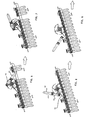
- Figures 4 to 9 are side views of the respective subsequent phases in which said mutually associated preforms are grasped, lifted out and ejected from the transfer line by means of an apparatus according to the present invention;
- Figures 10 and 11 are enlarged views of an arrangement according to the present invention, with and without a rotary-motion driving belt, respectively;
- Figure 12 is a top view of the arrangement according to the present invention, which is shown jointly with a portion of the corresponding transfer line;
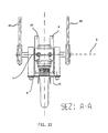
- Figure 13 is a view of the A-A section, referred to Figure 11, of the arrangement according to the present invention;
- Figure 14 is a side view of two preforms that are stuck into each other, in the state in which they must therefore be desirably removed from the production flow by means of the arrangement according to the present invention.
Claims (6)
- Apparatus for transferring preforms (1), comprising a pair of parallel rails (2, 3) separated by a groove-forming gap in which a plurality of preforms are inserted temporarily so as to be able to glide in an orderly sequence between said rails, which are arranged slopingly from an upper loading station (4) down to a lower unloading station (5), said apparatus being provided with an arrangement (6) adapted to:intercept the passage of pairs of preforms in which an inner preform (13) is inserted, with the closed end of the body thereof, in the aperture of a respective outer preform (12), said pair of preforms being supported by said rails by means of said parallel rails engaging the collar portion (26) of said outer preform, and said inner preform (13) moving forward at such a height that the respective collar (16) thereof is raised from the upper edge of said rails by a distance (H) that is greater than a pre-determined value.remove said pair of preforms (12, 13) from said plurality of preforms (1),to lift out and remove from said groove-forming gap said pairs of preforms (12, 13) of which one is inserted in the other one, characterized in thatsaid arrangement comprises a plurality of rotary forks (8), each one of which is provided with two outer parallel arms (9, 10) arranged above said rails,said arms being capable of moving into at least a first position (Fig. 4) in which the collar of said incoming inner preform is engaged by said arms, and a second position (Fig. 8) in which said arms lift said pairs of preforms out of said rails and rotate so as to remove and eject said pair of preforms from said rails,said forks being rotating around the same unique axis (X).
- Apparatus according to claim 1, characterized in that the end portions of said arms of said forks are spaced from each other by a distance that is greater than the diameter of the threaded portion of said preforms (1) and the diameter (d) of the cylindrical body of the preform below the respective collar.
- Apparatus according to claim 2, characterized in that the rotation of said forks takes place about a horizontal axis (X) extending transversally with respect to the vertical plane passing through said groove-forming gap and situated at a higher position above it.
- Apparatus according to claim 3, characterized in that the rotation of said arrangement is a continuous rotation, and that the rotation rate is such and the angle between said rotary forks is such that said forks are adapted to remove two successive and adjacent ones of said pairs of inner and outer preforms (12, 13) individually.
- Apparatus according to any of the preceding claims. characterized in that the arms of said forks are adapted to assume an orientation that is parallel to said rails when the distance (H) between said forks and said rails is equal to or slightly smaller than the distance between said rails and the collar (16) of said inner preform (13).
- Apparatus according to any of the preceding claims, characterized in that it is also provided with a protection member (22), preferably formed by a removably mounted bracket-like member, attached thereto by means of appropriate fastening means (24, 36) and situated immediately downstream of said arrangement above the respective portion of said rails.
Applications Claiming Priority (3)
| Application Number | Priority Date | Filing Date | Title |
|---|---|---|---|
| IT1998PN000074A IT1305277B1 (en) | 1998-10-20 | 1998-10-20 | DEVICE FOR THE IDENTIFICATION AND ELIMINATION OF PREFORMS HOOKED BY A CONTINUOUS TRANSFER LINE. |
| ITPN980074 | 1998-10-20 | ||
| PCT/EP1999/006516 WO2000023254A1 (en) | 1998-10-20 | 1999-09-04 | Arrangement for identifying and removing associated preforms from a continuous transfer line |
Publications (2)
| Publication Number | Publication Date |
|---|---|
| EP1140466A1 EP1140466A1 (en) | 2001-10-10 |
| EP1140466B1 true EP1140466B1 (en) | 2002-07-03 |
Family
ID=11395432
Family Applications (1)
| Application Number | Title | Priority Date | Filing Date |
|---|---|---|---|
| EP99970631A Expired - Lifetime EP1140466B1 (en) | 1998-10-20 | 1999-09-04 | Arrangement for identifying and removing associated preforms from a continuous transfer line |
Country Status (9)
| Country | Link |
|---|---|
| US (1) | US6575305B1 (en) |
| EP (1) | EP1140466B1 (en) |
| JP (1) | JP2002527267A (en) |
| AT (1) | ATE220000T1 (en) |
| CA (1) | CA2339057C (en) |
| DE (1) | DE69902056T2 (en) |
| ES (1) | ES2179701T3 (en) |
| IT (1) | IT1305277B1 (en) |
| WO (1) | WO2000023254A1 (en) |
Families Citing this family (23)
| Publication number | Priority date | Publication date | Assignee | Title |
|---|---|---|---|---|
| WO2002066231A1 (en) * | 2001-02-21 | 2002-08-29 | Stulic Miroslav | Transporting means to transport injection moulded preforms through a blow moulding apparatus |
| FR2864050B1 (en) * | 2003-12-23 | 2007-04-06 | Sidel Sa | PREFORM FEEDING SYSTEM HAVING A DEVICE FOR SELECTIVELY ELIMINATING MALLED POSITIONED PREFORMS |
| FR2864051B1 (en) * | 2003-12-23 | 2007-04-06 | Sidel Sa | SYSTEM FOR SUPPLYING PREFORMS, IN PARTICULAR A MACHINE FOR BLOWING CONTAINERS, COMPRISING MEANS FOR EJECTING PREFORMS NOT POSITIONED |
| US8807986B2 (en) | 2006-03-09 | 2014-08-19 | B & R Industries Pty. Ltd. | PET blow moulding machines |
| US7322458B1 (en) * | 2006-08-02 | 2008-01-29 | Norwalt Design Inc. | Orienting and feeding apparatus for manufacturing line |
| CH699222A1 (en) * | 2008-07-17 | 2010-01-29 | M Tanner Ag | Device and method for separating cylindrical bodies. |
| CH699223A1 (en) * | 2008-07-17 | 2010-01-29 | M Tanner Ag | Device and method for separating cylindrical bodies. |
| CH702406A1 (en) | 2009-12-11 | 2011-06-15 | M Tanner Ag | Apparatus for sorting out incorrectly positioned cylindrical bodies in a separating and conveying device. |
| DE102010008367A1 (en) * | 2010-02-17 | 2011-08-18 | Krones Ag, 93073 | Roller sorter and sorting method for sorting preforms and transport device with such roller sorter |
| CH704401A1 (en) * | 2011-01-28 | 2012-07-31 | M Tanner Ag | Conveyor for cylindrical bodies, with inclined in conveying direction delivery rails. |
| DE102011109542A1 (en) * | 2011-08-05 | 2013-02-07 | Krones Aktiengesellschaft | Transport and special device for plastic preforms |
| JP5972033B2 (en) * | 2012-05-02 | 2016-08-17 | サントリーホールディングス株式会社 | Preform supply device |
| DE102012011763A1 (en) * | 2012-06-15 | 2013-12-19 | Khs Corpoplast Gmbh | Device for transporting preforms |
| DE102012011762A1 (en) * | 2012-06-15 | 2013-12-19 | Khs Corpoplast Gmbh | Separating device for preforms with a device for separating out incorrectly positioned preforms |
| DE102012017699A1 (en) * | 2012-09-07 | 2014-03-13 | Khs Corpoplast Gmbh | Separating device for preforms |
| DE102014012528A1 (en) * | 2014-08-28 | 2016-03-03 | Khs Corpoplast Gmbh | Device and method for transporting preforms in the area of a blow molding machine |
| FR3035090B1 (en) * | 2015-04-16 | 2017-03-31 | Sidel Participations | "DEVICE FOR ALIGNING AND ADJUSTING PREFORMS COMPRISING A CENTRIFUGE BOWL EQUIPPED WITH MEASURING MEANS OF PREFORMING MALIGNANT PREFORMS" |
| FR3046998A1 (en) * | 2016-01-26 | 2017-07-28 | Gebo Packaging Solutions France | DEVICE AND METHOD FOR CONVEYING CONTROL |
| IT201600128336A1 (en) * | 2016-12-19 | 2018-06-19 | True Keg S R L | A SYSTEM FOR THE FEEDING OF PRE-FORM IN POLYMERIC MATERIALS TO A STIROSOFFIAGIACO MACHINE |
| IT201700072654A1 (en) * | 2017-06-28 | 2018-12-28 | Arol Spa | Method and apparatus for transferring items to and from a transport line |
| USD1003725S1 (en) | 2021-09-03 | 2023-11-07 | Graham Packaging Company, L.P. | Container |
| USD1010454S1 (en) | 2021-09-03 | 2024-01-09 | Graham Packaging Company, L.P. | Container |
| CN113879811B (en) * | 2021-09-27 | 2023-02-28 | 毅创智能装备(绍兴)有限公司 | Pallet fork overturning, assembling and conveying equipment |
Family Cites Families (11)
| Publication number | Priority date | Publication date | Assignee | Title |
|---|---|---|---|---|
| US2861685A (en) * | 1954-05-24 | 1958-11-25 | Cordis Nat | Litter remover for automatic poultry feeder |
| US2813616A (en) * | 1955-10-27 | 1957-11-19 | Deering Milliken Res Corp | Feed chute mechanism |
| US2911088A (en) * | 1957-01-02 | 1959-11-03 | Deering Milliken Res Corp | Handling arrangement for bobbins and the like |
| US3344901A (en) * | 1966-05-09 | 1967-10-03 | Arthur N Monaco | Overcap feed and orienting device |
| US3369642A (en) * | 1966-06-17 | 1968-02-20 | Richardson Merrell Inc | Apparatus for removing tipped-over bottles from a conveyor |
| US3811551A (en) * | 1973-01-15 | 1974-05-21 | Phillys Petroleum | Apparatus and method for orienting articles |
| US4244459A (en) * | 1978-01-26 | 1981-01-13 | Garrett Burton R | Parison unscrambler |
| US4350251A (en) * | 1979-04-19 | 1982-09-21 | Frito-Lay, Inc. | Apparatus and method for selectively ejecting malformed articles |
| FR2675481B1 (en) | 1991-04-16 | 1993-08-20 | Sidel Sa | AGENCY PREFORM CONVEYING DEVICE FOR ELIMINATING NESTED PREFORMS INTO OTHERS. |
| IT1294115B1 (en) * | 1997-01-29 | 1999-03-22 | Matteo Zoppas | PROCESS AND IMPROVED APPARATUS FOR THE PRODUCTION OF THERMOPLASTIC RESIN CONTAINERS |
| DE19705506C1 (en) | 1997-02-13 | 1998-10-01 | Siemens Ag | Contact spring arrangement for actuation by a rocker armature |
-
1998
- 1998-10-20 IT IT1998PN000074A patent/IT1305277B1/en active
-
1999
- 1999-09-04 WO PCT/EP1999/006516 patent/WO2000023254A1/en active IP Right Grant
- 1999-09-04 DE DE69902056T patent/DE69902056T2/en not_active Expired - Fee Related
- 1999-09-04 CA CA002339057A patent/CA2339057C/en not_active Expired - Fee Related
- 1999-09-04 JP JP2000577015A patent/JP2002527267A/en active Pending
- 1999-09-04 ES ES99970631T patent/ES2179701T3/en not_active Expired - Lifetime
- 1999-09-04 US US09/787,005 patent/US6575305B1/en not_active Expired - Fee Related
- 1999-09-04 AT AT99970631T patent/ATE220000T1/en not_active IP Right Cessation
- 1999-09-04 EP EP99970631A patent/EP1140466B1/en not_active Expired - Lifetime
Also Published As
| Publication number | Publication date |
|---|---|
| JP2002527267A (en) | 2002-08-27 |
| ES2179701T3 (en) | 2003-01-16 |
| US6575305B1 (en) | 2003-06-10 |
| WO2000023254A1 (en) | 2000-04-27 |
| DE69902056T2 (en) | 2002-10-31 |
| CA2339057A1 (en) | 2000-04-27 |
| EP1140466A1 (en) | 2001-10-10 |
| IT1305277B1 (en) | 2001-04-19 |
| DE69902056D1 (en) | 2002-08-08 |
| ATE220000T1 (en) | 2002-07-15 |
| CA2339057C (en) | 2004-10-19 |
| ITPN980074A1 (en) | 2000-04-20 |
Similar Documents
| Publication | Publication Date | Title |
|---|---|---|
| EP1140466B1 (en) | Arrangement for identifying and removing associated preforms from a continuous transfer line | |
| US7556137B2 (en) | Preform-supply device comprising a device for the selective removal of incorrectly-positioned longitudinal preforms | |
| US7258222B2 (en) | Article positioning machine | |
| US7337893B2 (en) | Preform feeder system, particularly of a receptacle blowing machine, comprising means for ejecting badly positioned preforms | |
| EP2499069B1 (en) | Unscrambling machine for containers and relative process | |
| CN101456485B (en) | A kind of pre-form sorting apparatus | |
| US5853080A (en) | Conveyor belt apparatus for bottles | |
| CN100562420C (en) | The centrifugal device that is used for level of supply placement and continuously arranged preform | |
| US20100011712A1 (en) | Beverage bottling or container filling plant having a beverage bottle or container handling machine and a method of operation thereof | |
| US9352507B2 (en) | Separator device for preforms | |
| CN107107448B (en) | For conveying the device and method of preform in the region of blow moulding machine | |
| US10315352B2 (en) | Device and method for transporting preforms in the region of a blow-molding machine | |
| WO1998057875A1 (en) | High speed automated cog sorter | |
| US6209708B1 (en) | Conveyor system for receiving, orienting and conveying pouches | |
| US20070051585A1 (en) | Apparatus and method for guiding and sorting packages and containers | |
| US20090120765A1 (en) | Apparatus and Method for Positioning Articles, Comprising Multiple Unloading Operations Per Cycle | |
| EP3366617B1 (en) | Apparatus and method for buffering the flow of articles | |
| KR20020022067A (en) | Conveyor system and installation for blow-moulding of containers | |
| US20100314216A1 (en) | Apparatus for unscrambling and orienting preforms or objects in general | |
| US11565894B2 (en) | Rotary discharge of containers from a depalletizer | |
| WO2001009017A1 (en) | Arrangement by conveyor for items, such as packaging bodies of glass, for example | |
| US7762467B2 (en) | Method and apparatus for use in packaging a selected number of containers | |
| JP3659478B2 (en) | Waste plastic multi-row alignment apparatus and method, and waste plastic sorting apparatus using the waste plastic multi-row alignment apparatus | |
| WO1996019302A1 (en) | A method and an apparatus for sorting containers | |
| KR200290583Y1 (en) | Automatic Vending Machine Capable Of Lifting Products |
Legal Events
| Date | Code | Title | Description |
|---|---|---|---|
| PUAI | Public reference made under article 153(3) epc to a published international application that has entered the european phase |
Free format text: ORIGINAL CODE: 0009012 |
|
| 17P | Request for examination filed |
Effective date: 20000922 |
|
| AK | Designated contracting states |
Kind code of ref document: A1 Designated state(s): AT BE CH CY DE DK ES FI FR GB GR IE IT LI LU MC NL PT SE |
|
| GRAG | Despatch of communication of intention to grant |
Free format text: ORIGINAL CODE: EPIDOS AGRA |
|
| 17Q | First examination report despatched |
Effective date: 20011105 |
|
| GRAG | Despatch of communication of intention to grant |
Free format text: ORIGINAL CODE: EPIDOS AGRA |
|
| GRAH | Despatch of communication of intention to grant a patent |
Free format text: ORIGINAL CODE: EPIDOS IGRA |
|
| GRAH | Despatch of communication of intention to grant a patent |
Free format text: ORIGINAL CODE: EPIDOS IGRA |
|
| GRAA | (expected) grant |
Free format text: ORIGINAL CODE: 0009210 |
|
| AK | Designated contracting states |
Kind code of ref document: B1 Designated state(s): AT DE ES FR GB IT |
|
| PG25 | Lapsed in a contracting state [announced via postgrant information from national office to epo] |
Ref country code: AT Free format text: LAPSE BECAUSE OF FAILURE TO SUBMIT A TRANSLATION OF THE DESCRIPTION OR TO PAY THE FEE WITHIN THE PRESCRIBED TIME-LIMIT Effective date: 20020703 |
|
| REF | Corresponds to: |
Ref document number: 220000 Country of ref document: AT Date of ref document: 20020715 Kind code of ref document: T |
|
| REG | Reference to a national code |
Ref country code: IE Ref legal event code: FG4D |
|
| REF | Corresponds to: |
Ref document number: 69902056 Country of ref document: DE Date of ref document: 20020808 |
|
| ET | Fr: translation filed | ||
| REG | Reference to a national code |
Ref country code: ES Ref legal event code: FG2A Ref document number: 2179701 Country of ref document: ES Kind code of ref document: T3 |
|
| PLBE | No opposition filed within time limit |
Free format text: ORIGINAL CODE: 0009261 |
|
| STAA | Information on the status of an ep patent application or granted ep patent |
Free format text: STATUS: NO OPPOSITION FILED WITHIN TIME LIMIT |
|
| 26N | No opposition filed |
Effective date: 20030404 |
|
| REG | Reference to a national code |
Ref country code: IE Ref legal event code: MM4A |
|
| PG25 | Lapsed in a contracting state [announced via postgrant information from national office to epo] |
Ref country code: GB Free format text: LAPSE BECAUSE OF NON-PAYMENT OF DUE FEES Effective date: 20030904 |
|
| GBPC | Gb: european patent ceased through non-payment of renewal fee | ||
| PGFP | Annual fee paid to national office [announced via postgrant information from national office to epo] |
Ref country code: FR Payment date: 20040812 Year of fee payment: 6 |
|
| PGFP | Annual fee paid to national office [announced via postgrant information from national office to epo] |
Ref country code: DE Payment date: 20040818 Year of fee payment: 6 |
|
| PGFP | Annual fee paid to national office [announced via postgrant information from national office to epo] |
Ref country code: ES Payment date: 20040906 Year of fee payment: 6 |
|
| PG25 | Lapsed in a contracting state [announced via postgrant information from national office to epo] |
Ref country code: IT Free format text: LAPSE BECAUSE OF NON-PAYMENT OF DUE FEES Effective date: 20050904 |
|
| PG25 | Lapsed in a contracting state [announced via postgrant information from national office to epo] |
Ref country code: ES Free format text: LAPSE BECAUSE OF NON-PAYMENT OF DUE FEES Effective date: 20050905 |
|
| PG25 | Lapsed in a contracting state [announced via postgrant information from national office to epo] |
Ref country code: DE Free format text: LAPSE BECAUSE OF NON-PAYMENT OF DUE FEES Effective date: 20060401 |
|
| PG25 | Lapsed in a contracting state [announced via postgrant information from national office to epo] |
Ref country code: FR Free format text: LAPSE BECAUSE OF NON-PAYMENT OF DUE FEES Effective date: 20060531 |
|
| REG | Reference to a national code |
Ref country code: FR Ref legal event code: ST Effective date: 20060531 |
|
| REG | Reference to a national code |
Ref country code: ES Ref legal event code: FD2A Effective date: 20050905 |