EP1140424B1 - An abrasive machine for machining a flange on a work piece - Google Patents
An abrasive machine for machining a flange on a work piece Download PDFInfo
- Publication number
- EP1140424B1 EP1140424B1 EP99965672A EP99965672A EP1140424B1 EP 1140424 B1 EP1140424 B1 EP 1140424B1 EP 99965672 A EP99965672 A EP 99965672A EP 99965672 A EP99965672 A EP 99965672A EP 1140424 B1 EP1140424 B1 EP 1140424B1
- Authority
- EP
- European Patent Office
- Prior art keywords
- shaft
- lid member
- machine
- housing
- inner space
- Prior art date
- Legal status (The legal status is an assumption and is not a legal conclusion. Google has not performed a legal analysis and makes no representation as to the accuracy of the status listed.)
- Expired - Lifetime
Links
Images


Classifications
-
- B—PERFORMING OPERATIONS; TRANSPORTING
- B24—GRINDING; POLISHING
- B24B—MACHINES, DEVICES, OR PROCESSES FOR GRINDING OR POLISHING; DRESSING OR CONDITIONING OF ABRADING SURFACES; FEEDING OF GRINDING, POLISHING, OR LAPPING AGENTS
- B24B5/00—Machines or devices designed for grinding surfaces of revolution on work, including those which also grind adjacent plane surfaces; Accessories therefor
- B24B5/01—Machines or devices designed for grinding surfaces of revolution on work, including those which also grind adjacent plane surfaces; Accessories therefor for combined grinding of surfaces of revolution and of adjacent plane surfaces on work
-
- B—PERFORMING OPERATIONS; TRANSPORTING
- B24—GRINDING; POLISHING
- B24B—MACHINES, DEVICES, OR PROCESSES FOR GRINDING OR POLISHING; DRESSING OR CONDITIONING OF ABRADING SURFACES; FEEDING OF GRINDING, POLISHING, OR LAPPING AGENTS
- B24B41/00—Component parts such as frames, beds, carriages, headstocks
- B24B41/06—Work supports, e.g. adjustable steadies
Definitions
- the present invention relates to an abrasive machine, in particular a grinder for removal of material from a flange on a work piece, the machine comprising a rotatably driven tool, chucking equipment for holding the work piece relative the rotatably driven tool and feeding means for effecting relative displacement between the work piece and the rotatably driven tool.
- Abrasive machines such as grinding machines, lapping machines, honing machines, milling machines, etc.
- the machine It is desirous that the machine be compact and as space-saving as possible.
- the co-operating parts of the machine have a high mutual stiffness and low tendencies of vibration.
- a machine which comprises a tubular cylindrical housing having a longitudinal cylindrical inner space.
- the cylindrical inner space has a longitudinal axis which is offset from the longitudinal axis of the housing.
- a shaft is arranged for angular displacement in the cylindrical inner space and has a recess accommodating a motor which is coupled to a rotatable work head.
- the work head together with the chucking equipment is arranged to hold and rotate a work piece to be treated.
- the housing is enclosed by a rotatably driven outer casing, with the casing being firmly connected to a lid member having an opening forming at its inner edge a tool, such as a grinding wheel.
- a tool such as a grinding wheel.
- the machines according to said Swedish patent applications are designed to be able to grind the outer and inner envelope surfaces respectively of annular work pieces.
- reference numeral 10 generally denotes an abrasive machine according to the present invention.
- the machine 10 incorporates a frame 11 which, in the shown embodiment, is designed as a machine bed having a portion 12 for supporting a cantilever housing.
- the cantilever housing is designed as an externally cylindrical and substantially tube-shaped elongate housing 13 extending about a longitudinal axis.
- the housing 13 is provided with a longitudinal cylindrical inner space 14 extending from a first end of the housing.
- the cylindrical inner space 14 has a longitudinal axis which is offset from the longitudinal axis of the cylindrical housing 13.
- the cylindrical housing 13 is preferably - although not necessarily - non-rotatably connected to the frame 11.
- a rotatable outer casing 15 Rotatably supported on the outer envelope surface of the cylindrical housing 13 is a rotatable outer casing 15, a wheel carriage, which is driven by a motor 16, preferably an electric motor, carried by the housing 13.
- a motor 16 preferably an electric motor
- the shaft 17 Inside the eccentric inner space 14 of the housing, there is provided a shaft 17 which can be revolved or indexed and displaced axially.
- the shaft 17 has a reduced diameter portion 18 projecting out from the housing inner space 14 in a direction towards the supporting portion 12 of the frame 11.
- the portion 18 of the shaft thus projecting from the housing is received in a space 19 provided in the portion 12 of the frame 11, and in which space there is provided means for revolving the shaft 17, preferably a torque motor 20, and means for axial displacement of the shaft 17, preferably a linear motor 21.
- the revolving and the axial displacement of the shaft is controlled by one or more sensors 22 and 23 respectively, which preferably are also accommodated in the space 19 of the frame portion 12. It is evident that the means for revolving and axially displacing the shaft need not be arranged in a manner as shown in the drawings, but may for instance be contained in a recessed portion of the shaft itself.
- the shaft 17 is provided with a recess 24.
- the recess extends substantially axially into the shaft 17 and is adapted to receive a motor 25, for example an electric motor.
- the motor 25 is provided with a spindle 26 which projects out of the recess 24.
- the motor is arranged within the recess such that the spindle 26 extends along an axis which is non-concentric with the longitudinal axis of the shaft 17.
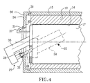
- the spindle extends along an axis which is substantially parallel to that of the longitudinal axis of the tubular cylindrical housing 13, whilst in the embodiments shown in Figs. 3 and 4, the spindle extends at an angle to the longitudinal axis of the housing 13.
- Chucking equipment cooperates with the spindle 26 to thereby hold and rotate a work piece 28.
- the work piece 28 may for example be an inner bearing race ring, though it is to be understood that any work piece having a surface which is to be treated can in principle be machined.
- the actual form of the chucking equipment 27 is of no particular significance and any conventional chuck arrangement which is suitable for clamping the work piece in question may be used, such as centric chucking, micro-centric chucking or magnetic chucking.
- the rotatable outer casing 15, or wheel carriage extends axially beyond the first end of the housing 13 and terminates in a peripheral flange 29.
- a lid member 30 is firmly connected to the outer casing 15 via the peripheral flange 29 such that the lid member co-rotates with the outer casing.
- the connection between the lid member 30 may be permanent, e.g. a welded joint, or releasable.
- the lid member 30 extends radially over the first end of the tubular cylindrical housing 13 and is provided with a central through opening 31 having a peripheral surface 32.
- the peripheral surface 32 extends from an interior surface 33 of the lid member 30. i.e. that surface facing the first end of the tubular cylindrical housing 13, to an exterior surface 34.
- the rotatably driven tool 35 comprises an annular region of abrasive material at least partially covering the peripheral surface 32 of the central through opening 31.
- the annular region of abrasive material extends axially beyond at least one, though preferably both, of the interior and exterior surfaces 33,34 of the lid member in the immediate vicinity of the through opening 31.
- the shaft 17 is arranged in the inner space 14 such that when the shaft executes an angular displacement in the inner space, the work piece 28 held by the chucking equipment 27 is caused to approach and contact the annular region of abrasive material 35.
- the rotatably driven tool 35 comprises an annular region of abrasive material on the interior surface 33 of the lid member 30, whilst in the embodiment illustrated in Fig. 4, the rotatably driven tool 35 comprises an annular region of abrasive material on the exterior surface 34 of the lid member 30.
- the peripheral surface 32 of the central through opening 31 in the lid member forms an angle to the longitudinal axis of the tubular cylindrical housing 13, which angle is greater than the angle subtended by the spindle 26.
- Machining can also be achieved by displacement of the shaft 17 using the motor 21 in the axial direction towards the annular region 35 of abrasive material.
- the abrasive material may be any material which is commonly used for grinding purposes.
- One example of such material is Cubic Boron Nitride.
- the abrasive material may be affixed to the lid member 30 by, for example, adhesive means or sintering.
- the chucking equipment advantageously comprises a support arm 36 extending parallel to the spindle 26 of the motor 25, with the support arm extending through the central through opening 31 of the lid member. In this manner, the work piece 28 can be supported at both axial ends.
- the embodiments of the invention may also be provided with a dressing tool 37 for ensuring the correct shape of the rotatably driven tool 35.
- the dressing tool 37 is in the form of a disc carried by the spindle 26 of the motor 25.
- the dressing tool 37 is carried by the shaft 17.
- the rotatably driven tool 35 in the Fig. 4 embodiment is on the exterior surface of the lid member 34, the dressing tool in this embodiment extends through the central through opening in the lid member 30.
- the machine 10 is operated in the following manner.
- the shaft 17 Since the shaft 17 is accommodated for rotation and axial displacement in the cylindrical inner space 14, and the inner space has a longitudinal axis which is offset from the longitudinal axis of the housing 13, it follows that rotation of the shaft 17 will cause the axis of the spindle 26 to approach or move away from the rotatably driven tool 35, depending on in which direction the shaft 17 is rotated.
- the shaft 17 within the tubular cylindrical housing 13 is caused to rotate in a first direction to thereby increase the distance between the spindle 26 and the rotatably driven tool 35 such that a gap is created which is sufficient to allow insertion of the work piece in the chucking equipment 37.
- the motor 25 ceases to rotate, the shaft 17 is displaced in the first direction and the work piece 28 is removed.
- the motor 25 and the outer casing 15 are rotated.
- the shaft 17 is axially displaced to the left as shown in Fig. 2 to cause the dressing tool 37 on the spindle 26 to approach the rotatably driven tool.
- the radial position of the dressing tool 37 relative the rotatably driven tool 35 can be adjusted.
- Dressing of the rotatably driven tool 35 in the embodiments shown in Figs. 3 and 4 is effected by axially displacing the shaft 17 such that the dressing tool 35 carried by the shaft 17 approaches the rotatably driven tool 35 whilst the outer casing 15 is rotated.
- the radial position of the dressing tool 37 relative the rotatably driven tool 35 can be adjusted.
- the cylindrical housing 13 has been shown having a cylindrical inner space.
- This space may also have a shape other than a cylindrical shape and the shaft 17 may have any appropriate cross-sectional shape which allows it to be turned or indexed within the inner space of the housing.
- the portion 18 of the shaft 17 received in the space 19 need not have a reduced diameter.
- the shaft be substituted for a system of articulated links or the like capable of turning or indexing the spindle in an appropriate manner.
Landscapes
- Engineering & Computer Science (AREA)
- Mechanical Engineering (AREA)
- Finish Polishing, Edge Sharpening, And Grinding By Specific Grinding Devices (AREA)
- Constituent Portions Of Griding Lathes, Driving, Sensing And Control (AREA)
- Grinding Of Cylindrical And Plane Surfaces (AREA)
Description
- Fig. 1
- shows in a schematic longitudinal sectional view an abrasive machine;
- Fig. 2
- is a schematic longitudinal sectional view on a greater scale of a part of the abrasive machine of Fig. 1;
- Fig. 3
- is a view corresponding to Fig. 2, though of a first embodiment of the abrasive machine according to the invention, and
- Fig. 4
- is a view corresponding to Fig. 2, though of a second embodiment of the abrasive machine according to the invention.
Claims (9)
- An abrasive machine (10), in particular a grinder for shaping a mantel surface of a substantially cylindrical work piece (28), said machine comprising a rotatably driven tool (35), chucking equipment (27) for holding said work piece relative said rotatably driven tool and feeding means (20,21) for effecting relative displacement between said work piece (28) and said rotatably driven tool (35),
characterized in that
said machine (10) further comprises:anda tubular cylindrical housing (13) extending about a longitudinal axis, said housing having a longitudinal cylindrical inner space (14) extending from a first end of said housing, said cylindrical inner space having a longitudinal axis which is offset from the longitudinal axis of said housing (13);a shaft (17) arranged in said inner space (14) for angular displacement therein, said shaft being provided with a recess;a motor (25) arranged in said recess;a spindle (26) coupled to said motor (25), said spindle extending at an angle to said longitudinal axis of said tubular cylindrical housing (13) and cooperating with said chucking equipment (27) to hold and rotate said work-piece (28);a rotatable outer casing (15) peripherally enclosing said tubular cylindrical housing (13),
a lid member (30) firmly connected to said outer casing (15) for co-rotation therewith, said lid member extending radially over said first end of said tubular cylindrical housing (13) with said lid member being provided with a central through opening (31) having an inner peripheral surface (32), said inner peripheral surface (32) extending from an axially interior surface (33) of said lid member facing said first end of said tubular cylindrical housing (13) to an axially exterior surface (34);
wherein said rotatably driven tool (35) comprises an annular region of abrasive material on said axially interior surface of said lid member, said annular region of abrasive material being concentric with said central through opening (31) of said lid member (30);
and wherein said shaft (17) is arranged in said inner space (14) such that when said shaft executes an angular displacement in said inner space, said work piece (28) held by said chucking equipment (27) is caused to approach and contact said annular region of abrasive material (35). - The machine as claimed in claim 1, characterized in that said peripheral surface (32) of said central through opening (31) in said lid member forms an angle to said longitudinal axis of said tubular cylindrical housing (13), which angle is greater than said angle subtended by said spindle (26).
- An abrasive machine (10), in particular a grinder for shaping a mantel surface of a substantially cylindrical work piece (28), said machine comprising a rotatably driven tool (35), chucking equipment (27) for holding said work piece relative said rotatably driven tool and feeding means (20,21) for effecting relative displacement between said work (28) and said rotatably driven tool (35),
characterized in that
said machine (10) further comprises:anda tubular cylindrical housing (13) extending about a longitudinal axis, said housing having a longitudinal cylindrical inner space (14) extending from a first end of said housing, said cylindrical inner space having a longitudinal axis which is offset from the longitudinal axis of said housing (13);a shaft (17) arranged in said inner space (14) for angular displacement therein, said shaft being provided with a recess;a motor (25) arranged in said recess;a spindle (26) coupled to said motor (25), said spindle extending at an angle to said longitudinal axis of said tubular cylindrical housing (13) and cooperating with said chucking equipment (27) to hold and rotate said work-piece (28);a rotatable outer casing (15) peripherally enclosing said tubular cylindrical housing (13),
a lid member (30) firmly connected to said outer casing (15) for co-rotation therewith, said lid member extending radially over said first end of said tubular cylindrical housing (13) with said lid member being provided with a central through opening (31) having an inner peripheral surface (32), said peripheral surface (32) extending from an axially interior surface (33) of said lid member facing said first end of said tubular cylindrical housing (13) to an axially exterior surface (34);
wherein said rotatably driven tool (35) comprises an annular region of abrasive material on said axially exterior surface of said lid member, said annular region of abrasive material being concentric with said central through opening (31) of said lid member;
and wherein said shaft (17) is arranged in. said inner space (14) such that when said shaft executes an angular displacement in said inner space, said work piece (28) held by said chucking equipment (27) is caused to approach and contact said annular region of abrasive material. - The machine as claimed in any one of claims 1 to 3, characterized in that a dressing tool (37) is carried by said shaft (17).
- The machine as claimed in any one of the preceding claims, characterized in that said shaft (17) is acted upon by means (21) for effecting axial displacement of said shaft (17).
- The machine as claimed in any one of the preceding claims, characterized in that said chucking equipment (27) comprises a support arm (36) extending substantially parallel to said spindle (26) of said motor, said support arm extending through said central through opening (31) of said lid member (30).
- The machine as claimed in any one of the preceding claims, characterized in that said lid member (30) is releasably connected to said outer casing (15).
- The machine as claimed in any one of claims 5-7, characterized in that said shaft (17) is provided with sensors (22,23) for controlling rotational and axial displacement of said shaft (17).
- The machine as claimed in any one of the preceding claims, characterized in that said machine further comprises a support frame (11) to which said tubular cylindrical housing (13) is fixedly attached, and in that said outer casing (15) is driven by a motor (16) carried by the housing.
Applications Claiming Priority (3)
| Application Number | Priority Date | Filing Date | Title |
|---|---|---|---|
| SE9804618 | 1998-12-30 | ||
| SE9804618A SE516932C2 (en) | 1998-12-30 | 1998-12-30 | Abrasive machine, especially a grinding machine, for removing material from a flange on a workpiece |
| PCT/SE1999/002442 WO2000040368A1 (en) | 1998-12-30 | 1999-12-21 | An abrasive machine for machining a flange on a work piece |
Publications (2)
| Publication Number | Publication Date |
|---|---|
| EP1140424A1 EP1140424A1 (en) | 2001-10-10 |
| EP1140424B1 true EP1140424B1 (en) | 2002-10-30 |
Family
ID=20413924
Family Applications (1)
| Application Number | Title | Priority Date | Filing Date |
|---|---|---|---|
| EP99965672A Expired - Lifetime EP1140424B1 (en) | 1998-12-30 | 1999-12-21 | An abrasive machine for machining a flange on a work piece |
Country Status (9)
| Country | Link |
|---|---|
| US (1) | US6435954B1 (en) |
| EP (1) | EP1140424B1 (en) |
| JP (1) | JP3656735B2 (en) |
| CN (1) | CN1094812C (en) |
| AU (1) | AU2136000A (en) |
| DE (1) | DE69903751T2 (en) |
| SE (1) | SE516932C2 (en) |
| TW (1) | TW434097B (en) |
| WO (1) | WO2000040368A1 (en) |
Families Citing this family (1)
| Publication number | Priority date | Publication date | Assignee | Title |
|---|---|---|---|---|
| CN119426709B (en) * | 2025-01-10 | 2025-05-23 | 江苏宣胜金属科技有限公司 | Seamless steel pipe crop device |
Family Cites Families (7)
| Publication number | Priority date | Publication date | Assignee | Title |
|---|---|---|---|---|
| SU401474A1 (en) * | 1971-07-06 | 1973-10-12 | WAY OF FINAL PROCESSING | |
| SU542627A1 (en) * | 1974-08-19 | 1977-01-15 | Всесоюзный Научно-Исследовательский Конструкторско-Технологический Институт Подшипниковой Промышленности Минский Филиал | Apparatus for grinding outer surfaces of rotation, preferably, grooves of inner rings of rolling bearings |
| SU1079412A1 (en) * | 1982-04-19 | 1984-03-15 | Куйбышевский ордена Трудового Красного Знамени политехнический институт им.В.В.Куйбышева | Method of grinding a surface of revolution |
| SE511599C2 (en) * | 1997-07-04 | 1999-10-25 | Lidkoeping Machine Tools Ab | Internally abrading machine |
| SE511542C2 (en) * | 1997-07-04 | 1999-10-18 | Lidkoeping Machine Tools Ab | Externally abrading machine |
| SE511598C2 (en) * | 1997-07-04 | 1999-10-25 | Lidkoeping Machine Tools Ab | Double plane abrading machine |
| SE512250C2 (en) * | 1998-07-10 | 2000-02-21 | Lidkoeping Machine Tools Ab | Abrasive machine for machining the end surface of a workpiece |
-
1998
- 1998-12-30 SE SE9804618A patent/SE516932C2/en not_active IP Right Cessation
-
1999
- 1999-12-21 WO PCT/SE1999/002442 patent/WO2000040368A1/en not_active Ceased
- 1999-12-21 JP JP2000592104A patent/JP3656735B2/en not_active Expired - Fee Related
- 1999-12-21 AU AU21360/00A patent/AU2136000A/en not_active Abandoned
- 1999-12-21 DE DE69903751T patent/DE69903751T2/en not_active Expired - Fee Related
- 1999-12-21 EP EP99965672A patent/EP1140424B1/en not_active Expired - Lifetime
- 1999-12-21 CN CN99815276A patent/CN1094812C/en not_active Expired - Fee Related
- 1999-12-30 TW TW088123305A patent/TW434097B/en active
-
2001
- 2001-06-29 US US09/893,401 patent/US6435954B1/en not_active Expired - Fee Related
Also Published As
| Publication number | Publication date |
|---|---|
| WO2000040368A1 (en) | 2000-07-13 |
| AU2136000A (en) | 2000-07-24 |
| TW434097B (en) | 2001-05-16 |
| JP2002534278A (en) | 2002-10-15 |
| DE69903751D1 (en) | 2002-12-05 |
| US6435954B1 (en) | 2002-08-20 |
| US20020025766A1 (en) | 2002-02-28 |
| CN1332665A (en) | 2002-01-23 |
| SE9804618L (en) | 2000-07-01 |
| SE516932C2 (en) | 2002-03-26 |
| SE9804618D0 (en) | 1998-12-30 |
| CN1094812C (en) | 2002-11-27 |
| JP3656735B2 (en) | 2005-06-08 |
| EP1140424A1 (en) | 2001-10-10 |
| DE69903751T2 (en) | 2003-07-24 |
Similar Documents
| Publication | Publication Date | Title |
|---|---|---|
| US6241590B1 (en) | External abrasive machine | |
| US6350187B2 (en) | Abrasive machine | |
| US6322423B1 (en) | Internal abrasive machine | |
| US6435954B1 (en) | Abrasive machine for machining a flange on a work piece | |
| US6461229B2 (en) | Abrasive machine for machining a surface of a cylindrical work piece | |
| JPH02237764A (en) | Grinding aligning round work piece | |
| MXPA00000123A (en) | External abrasive machine | |
| MXPA00000093A (en) | Internal abrasive machine | |
| TH38371A (en) | Inner polishing machine | |
| TH39211A (en) | polisher |
Legal Events
| Date | Code | Title | Description |
|---|---|---|---|
| PUAI | Public reference made under article 153(3) epc to a published international application that has entered the european phase |
Free format text: ORIGINAL CODE: 0009012 |
|
| 17P | Request for examination filed |
Effective date: 20010626 |
|
| AK | Designated contracting states |
Kind code of ref document: A1 Designated state(s): AT BE CH CY DE DK ES FI FR GB GR IE IT LI LU MC NL PT SE Kind code of ref document: A1 Designated state(s): DE FR GB |
|
| GRAG | Despatch of communication of intention to grant |
Free format text: ORIGINAL CODE: EPIDOS AGRA |
|
| 17Q | First examination report despatched |
Effective date: 20020206 |
|
| GRAG | Despatch of communication of intention to grant |
Free format text: ORIGINAL CODE: EPIDOS AGRA |
|
| GRAH | Despatch of communication of intention to grant a patent |
Free format text: ORIGINAL CODE: EPIDOS IGRA |
|
| GRAH | Despatch of communication of intention to grant a patent |
Free format text: ORIGINAL CODE: EPIDOS IGRA |
|
| GRAA | (expected) grant |
Free format text: ORIGINAL CODE: 0009210 |
|
| AK | Designated contracting states |
Kind code of ref document: B1 Designated state(s): DE FR GB |
|
| REG | Reference to a national code |
Ref country code: GB Ref legal event code: FG4D |
|
| RIN1 | Information on inventor provided before grant (corrected) |
Inventor name: HEIJKENSKJOELD, MATS |
|
| REF | Corresponds to: |
Ref document number: 69903751 Country of ref document: DE Date of ref document: 20021205 |
|
| ET | Fr: translation filed | ||
| PLBE | No opposition filed within time limit |
Free format text: ORIGINAL CODE: 0009261 |
|
| STAA | Information on the status of an ep patent application or granted ep patent |
Free format text: STATUS: NO OPPOSITION FILED WITHIN TIME LIMIT |
|
| 26N | No opposition filed |
Effective date: 20030731 |
|
| PGFP | Annual fee paid to national office [announced via postgrant information from national office to epo] |
Ref country code: DE Payment date: 20081219 Year of fee payment: 10 |
|
| PGFP | Annual fee paid to national office [announced via postgrant information from national office to epo] |
Ref country code: GB Payment date: 20081216 Year of fee payment: 10 |
|
| PGFP | Annual fee paid to national office [announced via postgrant information from national office to epo] |
Ref country code: FR Payment date: 20081215 Year of fee payment: 10 |
|
| GBPC | Gb: european patent ceased through non-payment of renewal fee |
Effective date: 20091221 |
|
| REG | Reference to a national code |
Ref country code: FR Ref legal event code: ST Effective date: 20100831 |
|
| PG25 | Lapsed in a contracting state [announced via postgrant information from national office to epo] |
Ref country code: FR Free format text: LAPSE BECAUSE OF NON-PAYMENT OF DUE FEES Effective date: 20091231 |
|
| PG25 | Lapsed in a contracting state [announced via postgrant information from national office to epo] |
Ref country code: DE Free format text: LAPSE BECAUSE OF NON-PAYMENT OF DUE FEES Effective date: 20100701 |
|
| PG25 | Lapsed in a contracting state [announced via postgrant information from national office to epo] |
Ref country code: GB Free format text: LAPSE BECAUSE OF NON-PAYMENT OF DUE FEES Effective date: 20091221 |