EP1140408B2 - Schneideinsatz und werkzeug mit schneideinsatz - Google Patents
Schneideinsatz und werkzeug mit schneideinsatz Download PDFInfo
- Publication number
- EP1140408B2 EP1140408B2 EP99962100A EP99962100A EP1140408B2 EP 1140408 B2 EP1140408 B2 EP 1140408B2 EP 99962100 A EP99962100 A EP 99962100A EP 99962100 A EP99962100 A EP 99962100A EP 1140408 B2 EP1140408 B2 EP 1140408B2
- Authority
- EP
- European Patent Office
- Prior art keywords
- cutting
- cutting insert
- corner
- indentation
- cutting edge
- Prior art date
- Legal status (The legal status is an assumption and is not a legal conclusion. Google has not performed a legal analysis and makes no representation as to the accuracy of the status listed.)
- Expired - Lifetime
Links
- 238000007373 indentation Methods 0.000 claims abstract description 23
- 238000003801 milling Methods 0.000 claims abstract description 10
- 229910001060 Gray iron Inorganic materials 0.000 claims abstract 2
- 238000003754 machining Methods 0.000 claims description 4
- 238000009499 grossing Methods 0.000 claims 1
- 230000015572 biosynthetic process Effects 0.000 description 2
- 238000005755 formation reaction Methods 0.000 description 2
- 238000009434 installation Methods 0.000 description 2
- 230000009467 reduction Effects 0.000 description 2
- 230000006835 compression Effects 0.000 description 1
- 238000007906 compression Methods 0.000 description 1
- 238000005553 drilling Methods 0.000 description 1
- 238000005516 engineering process Methods 0.000 description 1
- 238000005259 measurement Methods 0.000 description 1
- 238000004513 sizing Methods 0.000 description 1
- 238000007711 solidification Methods 0.000 description 1
- 230000008023 solidification Effects 0.000 description 1
Images


Classifications
-
- B—PERFORMING OPERATIONS; TRANSPORTING
- B23—MACHINE TOOLS; METAL-WORKING NOT OTHERWISE PROVIDED FOR
- B23B—TURNING; BORING
- B23B27/00—Tools for turning or boring machines; Tools of a similar kind in general; Accessories therefor
- B23B27/14—Cutting tools of which the bits or tips or cutting inserts are of special material
- B23B27/141—Specially shaped plate-like cutting inserts, i.e. length greater or equal to width, width greater than or equal to thickness
- B23B27/143—Specially shaped plate-like cutting inserts, i.e. length greater or equal to width, width greater than or equal to thickness characterised by having chip-breakers
-
- B—PERFORMING OPERATIONS; TRANSPORTING
- B23—MACHINE TOOLS; METAL-WORKING NOT OTHERWISE PROVIDED FOR
- B23B—TURNING; BORING
- B23B2200/00—Details of cutting inserts
- B23B2200/04—Overall shape
- B23B2200/0404—Hexagonal
-
- Y—GENERAL TAGGING OF NEW TECHNOLOGICAL DEVELOPMENTS; GENERAL TAGGING OF CROSS-SECTIONAL TECHNOLOGIES SPANNING OVER SEVERAL SECTIONS OF THE IPC; TECHNICAL SUBJECTS COVERED BY FORMER USPC CROSS-REFERENCE ART COLLECTIONS [XRACs] AND DIGESTS
- Y10—TECHNICAL SUBJECTS COVERED BY FORMER USPC
- Y10T—TECHNICAL SUBJECTS COVERED BY FORMER US CLASSIFICATION
- Y10T407/00—Cutters, for shaping
- Y10T407/23—Cutters, for shaping including tool having plural alternatively usable cutting edges
- Y10T407/235—Cutters, for shaping including tool having plural alternatively usable cutting edges with integral chip breaker, guide or deflector
-
- Y—GENERAL TAGGING OF NEW TECHNOLOGICAL DEVELOPMENTS; GENERAL TAGGING OF CROSS-SECTIONAL TECHNOLOGIES SPANNING OVER SEVERAL SECTIONS OF THE IPC; TECHNICAL SUBJECTS COVERED BY FORMER USPC CROSS-REFERENCE ART COLLECTIONS [XRACs] AND DIGESTS
- Y10—TECHNICAL SUBJECTS COVERED BY FORMER USPC
- Y10T—TECHNICAL SUBJECTS COVERED BY FORMER US CLASSIFICATION
- Y10T407/00—Cutters, for shaping
- Y10T407/24—Cutters, for shaping with chip breaker, guide or deflector
- Y10T407/245—Cutters, for shaping with chip breaker, guide or deflector comprising concave surface in cutting face of tool
Definitions
- the invention relates to a cutting insert according to the preamble of claim 1 (e.g., U.S. 4,441,841).
- the invention further relates to a tool consisting from a tool holder with at least one Recess for receiving such a cutting insert.
- Milling operations are often done in two operations carried out a roughing (roughing) and a sizing. That can be combined in one Roughing-finishing tool thereby taken into account be that part of the recesses provided in (Plate seats) of the tool holder clamped Cutting inserts as pure roughing tools and the others are used as finishing tools. Examples of finishing cutting inserts are in the description of the next level the technology representing DE 197 03 569 A1.
- the local cutting insert preferably a has regular hexagonal rake face, has several Main cutting and adjoining In addition to cutting. As described in this document, is a local cutting insert in combination with a pure cutting insert used for roughing.
- Cutting insert points to the secondary cutting edge a concave chip forming groove whose radius is between 0.5 mm and 0.8 mm. Through this chip forming groove should the Maumonyspanwinkel between 10 ° and 20 ° can be adjusted. Also along the main cutting edge a Spanformnut extending in the Cross section measured radius of curvature of 0.5 mm. About pure roughing inserts nothing is executed in this document.
- a cutting insert which has indentations in the rake face along the cutting edges whose width or greatest extent parallel to the cutting edge is greater than the distance between two adjacent indentations.
- Each of these impressions breaks through the cutting edge, which is thereby changed in the form of openings in the form, ie, it no longer forms a straight line, but has in the region of the apertures on formations, which are seen in the chip flow direction behind the straight cutting edge parts.
- the area of a cutting corner should be free of indentations and instead have a flat rake surface piece or a negative solidification surface in order to avoid amplified chip form upsetting in the corner area.
- the mentioned indentations can after the DE 28 40 610 C2 be arranged in a running along the cutting edge Spanformmulde.
- a trigonförmiger cutting insert is addressed for drilling, which is unsuitable for roughing milling.
- US-A 4,710,069 describes a cutting insert, along its cutting edge a chamfer and following the chamfer to cutting edge remote area has a groove-shaped recess.
- the Borderline between said chamfer and the groove-shaped Recess is equally spaced by several pierced arranged wells whose Depth should be less than 0.1 mm.
- the wells are essentially part-spherical recesses with a Radius of curvature of 0.5 mm.
- Such cutting inserts are only for turning-cutting suitable.
- the indentation a partial spherical segment in the cutting edge area arranged and breaks both adjacent there Cutting edges.
- the radius of curvature of the concave indentations between 4 mm and 10 mm.
- the maximum depth the indentation is not greater than 0.4 mm to 0.6 mm.
- the cutting insert is used during milling so used that preferably only the of the cutting edge sloping concave cutting edge part on both sides of the cutting edge effectively cuts. Depending on the desired depth of cut, the maximum depends Width of indentation in the cutting edge area. In the area of effective cutting edge closes in each case a conditional by the trough sloping flank part, which can be any desired positive rake angle creates.
- the indentation is symmetrical arranged to Schneiseewinkel horrierenden.
- the maximum diameter of the indentation is 4 mm.
- the rake angle ⁇ 0 in the cutting edge area should be between + 5 ° and + 20 °, preferably between + 8 ° and + 15 °.
- the cutting insert not only on one Side, but on both the roof surface and on the floor space can be used is to create a two-sided bearing surface a middle Span configurationplateau provided, which is the cutting edge plane surmounted.
- the middle cutting surface plateau has according to a further embodiment of the invention nose-shaped projections in the rear area protrude the impressions.
- the inventive Cutting insert s a regular 6-corner shape, at the respective adjacent cutting edges arranged at an obtuse angle of 120 ° are.
- the cutting edges are rounded, followed by an embodiment of the invention, the Schneifactabrundung a radius between 0.4 mm and 3 mm having.
- the cutting insert is designed to be used on both sides, so that twelve result in cutting edges that can be used for cutting.
- the cutting insert according to the invention is preferably used and fastened in a tool holder designed as a cutter body in a recess (insert seat) provided for this purpose.
- a recess insert seat
- For fixing serve clamping wedges for fixing the cutting insert with respect to the tool axis.
- an alignment of the cutting inserts for roughing is selected in which an effective axial rake angle ⁇ p of + 5 ° to + 10 ° and / or an effective radial rake angle ⁇ f of 0 ° to + 8 ° in the cutting insert recess results.
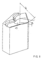
- the cutting insert 11 shown in the drawings has a regular-hexagonal shaped rake face, which is bounded by six cutting edges 12, of which adjacent cutting edges 12 form a cutting corner 13.
- the cutting edges 13 are rounded. wherein the cutting edges 12 respective flat open spaces 14 and the cutting edges rounded open space sections 15 join.
- On the rake surface of the cutting insert has a central rake surface plateau, which is formed in a star shape and in each case in the direction of the cutting edge projecting nose-shaped projections 17 shows. Between two cutting corners further projections 18 are arranged, which are directed approximately to the center of the respective cutting edge 12.
- the cutting insert 11 has according to the invention spherical indentations 19 in the region of each cutting corner 13 on the rake face.
- the nose-shaped projections 17 and 18 consist of a lower concave portion extending and an upper convex Part. However, the projections may also have flat sloping flanks or convex or concave flanks.
- the indexable insert has a thickness d of, for example, 5.56 mm and an in-circle diameter of 16.2 mm.
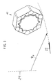
- the double-sided indexable insert is preferably used for milling in a tool holder which rotates about the axis of rotation 21.
- the cutting inserts 11 run on a cutter radius R f , wherein the cutting insert is moved (in addition to other roughing cutting inserts in the direction of the arrow 22.
- the machining operation carried out in this case is shown in detail in Fig. 6.
- the workpiece 23 is provided with a face milling cutter in a depth of cut a p processed with a plurality of roughing cutting inserts 11 are used.
- FIG. 5 shows, based on a cutting depth a p of, for example, 0.5 mm, a rake angle ⁇ 0 at a distance b of approximately 0.5 mm from the cutting edge of a measurement length which corresponds approximately to the tooth advance f z selected here with 0.5 mm ,
- the ball radius R K in question is between 4 mm and 10 mm, the maximum dome depth t at values below 0.4 mm to 0.6 mm.
- FIG. 9 shows the rake angle ⁇ at which the rake face area adjoining the rectilinear part of the cutting edge 12 is inclined.
- the radial rake angle ⁇ f which results from the installation position of the cutting insert in the tool holder, is shown in FIG.
- Mills stocked with cutting inserts 11 have been used to cut a workpiece 23.
- reductions in the passive force F p of about 40% are evident.
Landscapes
- Engineering & Computer Science (AREA)
- Mechanical Engineering (AREA)
- Milling Processes (AREA)
- Cutting Tools, Boring Holders, And Turrets (AREA)
- Control And Other Processes For Unpacking Of Materials (AREA)
Description
DE 28 40 610 C2 auch in einer entlang der Schneidkante verlaufenden Spanformmulde angeordnet sein. Insbesondere wird in der genannten Druckschrift ein trigonförmiger Schneideinsatz zum Bohren angesprochen, der für Schrupp-Fräsarbeiten ungeeignet ist.
- Fig. 1
- eine erfindungsgemäße Wendeschneidplatte in einer Frontansicht,
- Fig. 2
- eine Teilschnittansicht dieser Wendeschneidplatte,
- Fig. 3
- die Wendeschneidplatte in bezug auf ihre Einbaulage,
- Fig. 4, 5
- jeweils Teilansichten der erfindungsgemäßen Wendeschneidplatte zur Darstellung der Spanwinkel im Eckenbereich,
- Fig. 6
- denselben Teilbereich nach Fig. 5 beim FräsEinsatz,
- Fig. 7, 8
- jeweils Teilansichten eines Schneideckenbereiches zur Veranschaulichung der KugelkalottenFormgestaltung und -lage,
- Fig. 9
- Schneidecken-Teilansicht zur Darstellung des Schneidkanten-Spanwinkels γ auf der Spanfläche,
- Fig. 10
- Schneidecken-Teilansicht zur Darstellung des radialen Spanwinkels γr.
Claims (8)
- Schneideinsatz (11) zur spanenden Bearbeitung von Werkstücken (23), nämlich zur Schrupp-Schlicht-Bearbeitung beim Grauguss-Plan-Fräsen, mit mehreren die Spanfläche begrenzenden Schneidkanten (12), von denen zwei aneinandergrenzende Schneidkanten (12) eine Schneidecke (13) bilden und mit mindestens einer muldenförmigen, die Schneidkante (12) durchbrechenden Eindrückung, wobei die Eindrückung (19) im Schneideckenbereich (13) angeordnet ist und beide dort angrenzenden Schneidkanten (12) durchbricht
dadurch gekennzeichnet, dass die Eindrückung (19) ein Teilkugelsegment ist und dass der Spanwinkel (γ0) im Schneideckenbereich zwischen +5° und +20° liegt, wobei die Eindrückung (19) einen Krümmungsradius (RK) zwischen 4 mm und 10 mm aufweist und die maximale Tiefe (t) der Eindrückung (19) zwischen 0,4 mm und 0,6 mm liegt. - Schneideinsatz nach Anspruch 1, dadurch gekennzeichnet, dass die Eindrückung (19) symmetrisch zur Schneideckenwinkelhalbierenden angeordnet ist.
- Schneideinsatz nach einem der Ansprüche 1 oder 2, dadurch gekennzeichnet, dass der maximale Durchmesser (d) der Eindrückung (19) 4 mm beträgt.
- Schneideinsatz nach einem der Ansprüche 1 bis 3, dadurch gekennzeichnet, dass der Spanwinkel (γ0) im Schneideckenbereich zwischen +8° und +15° liegt.
- Schneideinsatz nach einem der Ansprüche 1 bis 4, dadurch gekennzeichnet, dass in der Spanfläche ein mittleres Spanflächenplateau (16) mit einem in den rückwärtigen Bereich der Eindrückung (19) hineinragenden nasenförmigen Vorsprung (17) angeordnet ist.
- Schneideinsatz nach einem der Ansprüche 1 bis 5, gekennzeichnet durch eine regelmäßige 6-Eck-Form, vorzugsweise mit abgerundeten Schneidecken (13).
- Schneideinsatz nach Anspruch 6, dadurch gekennzeichnet, dass die Schneideckenabrundung einen Radius zwischen 0,4 mm und 3 mm aufweist.
- Werkzeug, bestehend aus einem Werkzeughalter mit mindestens einer Ausnehmung zur Aufnahme eines Schneideinsatzes (11) nach einem der Ansprüche 1 bis 7, dadurch gekennzeichnet, dass der Schneideinsatz (11) unter einem effektiven axialen Spanwinkel (γp) von +5° bis +10° und/oder einem effektiven radialen Spanwinkel (γf) von 0° bis +8° in der Schneideinsatzausnehmung angeordnet ist.
Applications Claiming Priority (3)
| Application Number | Priority Date | Filing Date | Title |
|---|---|---|---|
| DE29822553U DE29822553U1 (de) | 1998-12-18 | 1998-12-18 | Schneideinsatz und Werkzeug mit Schneideinsatz |
| DE29822553U | 1998-12-18 | ||
| PCT/DE1999/003785 WO2000037205A1 (de) | 1998-12-18 | 1999-11-25 | Schneideinsatz und werkzeug mit schneideinsatz |
Publications (3)
| Publication Number | Publication Date |
|---|---|
| EP1140408A1 EP1140408A1 (de) | 2001-10-10 |
| EP1140408B1 EP1140408B1 (de) | 2002-07-03 |
| EP1140408B2 true EP1140408B2 (de) | 2005-01-05 |
Family
ID=8066823
Family Applications (1)
| Application Number | Title | Priority Date | Filing Date |
|---|---|---|---|
| EP99962100A Expired - Lifetime EP1140408B2 (de) | 1998-12-18 | 1999-11-25 | Schneideinsatz und werkzeug mit schneideinsatz |
Country Status (7)
| Country | Link |
|---|---|
| US (1) | US6641337B1 (de) |
| EP (1) | EP1140408B2 (de) |
| AT (1) | ATE219982T1 (de) |
| DE (2) | DE29822553U1 (de) |
| ES (1) | ES2176039T3 (de) |
| PT (1) | PT1140408E (de) |
| WO (1) | WO2000037205A1 (de) |
Families Citing this family (15)
| Publication number | Priority date | Publication date | Assignee | Title |
|---|---|---|---|---|
| SE525875C2 (sv) * | 2002-11-13 | 2005-05-17 | Sandvik Ab | Skär för skärverktyg med upphöjd övergångsyta |
| US7073423B2 (en) | 2003-09-17 | 2006-07-11 | Robotic Production Technology, Inc. | Compliance device for trimming a workpiece |
| DE102005033920A1 (de) * | 2005-07-20 | 2007-01-25 | Kennametal Inc. | Schneideinsatz, Werkzeug sowie Verfahren zur spanenden Bearbeitung eines Werkstücks |
| USD640716S1 (en) | 2007-07-05 | 2011-06-28 | Mitsubishi Materials Corporation | Cutting insert |
| USD644255S1 (en) * | 2010-08-25 | 2011-08-30 | Sandvik Intellectual Property Ab | Cutting insert for chip removing machining |
| US9475134B2 (en) | 2011-12-19 | 2016-10-25 | Iscar, Ltd. | Cutting insert and cutting tool |
| US20150023744A1 (en) * | 2013-07-22 | 2015-01-22 | Kennametal Inc. | Cutting insert with chip dividers |
| USD718356S1 (en) * | 2013-12-03 | 2014-11-25 | Hard Metal Advantage, L.L.C. | Hexagonal chip with elongated side notches |
| USD760308S1 (en) * | 2014-09-26 | 2016-06-28 | Kennametal India Limited | Cutting insert with flower-shaped seating area |
| AT15155U1 (de) | 2016-02-26 | 2017-01-15 | Ceratizit Austria Gmbh | Schälplatte |
| USD815164S1 (en) * | 2017-02-09 | 2018-04-10 | Kennametal Inc. | Cutting insert with corner radii cutting surfaces |
| USD832319S1 (en) * | 2017-02-15 | 2018-10-30 | Kennametal Inc. | Cutting insert with four-lobed seating area |
| DE102020115987A1 (de) | 2019-07-05 | 2021-01-07 | Kennametal India Limited | Beidseitige, polygonale wendeschneidplatte mit abwechselnd konkaven und konvexen schneidkanten |
| USD938503S1 (en) * | 2019-08-21 | 2021-12-14 | Rapid Granulator Ab | Ripper for granulating machine |
| DE102019123912A1 (de) * | 2019-09-05 | 2021-03-11 | Kennametal Inc. | Schneideinsatz sowie Schneidwerkzeug |
Family Cites Families (18)
| Publication number | Priority date | Publication date | Assignee | Title |
|---|---|---|---|---|
| SE311795B (de) * | 1966-06-01 | 1969-06-23 | Sandvikens Jernverks Ab | |
| CH569538A5 (de) * | 1973-03-30 | 1975-11-28 | Stellram Sa | |
| JPS5821602Y2 (ja) * | 1978-10-06 | 1983-05-09 | 住友電気工業株式会社 | スロ−アウエイチツプ |
| DE3029741A1 (de) * | 1980-08-06 | 1982-04-01 | Metallgesellschaft Ag, 6000 Frankfurt | Verfahren zum kontinuierlichen direkten schmelzen von metallischem blei aus schwefelhaltigen bleimaterialien |
| US4335984A (en) * | 1980-11-05 | 1982-06-22 | Raymond Zweekly | Metalcutting insert for roughing and finishing |
| US4465412A (en) * | 1982-09-07 | 1984-08-14 | The Valeron Corporation | Chip breaking insert for metal cutting tools |
| KR930011655B1 (ko) * | 1988-08-25 | 1993-12-16 | 스미도모덴기고오교오 가부시기가이샤 | 나사절삭용 드로우 어웨이팁 |
| SE467397B (sv) * | 1988-09-22 | 1992-07-13 | Sandvik Ab | Skaer foer spaanavskiljande bearbetning, daer de inboerdes avstaanden mellan aasar belaegna i spaanformaren minskar i riktning mot skaerkantens mitt |
| SE465958B (sv) * | 1988-09-26 | 1991-11-25 | Sandvik Ab | Dubbelsidigt skaer |
| FR2636870B1 (fr) * | 1988-09-29 | 1994-05-13 | Safety Sa | Insert de coupe |
| GB8827303D0 (en) * | 1988-11-23 | 1988-12-29 | Shell Int Research | Preparation of conjugated dienes |
| US4986151A (en) * | 1989-04-17 | 1991-01-22 | Horn Daniel T | Tool holder for a screw machine box tool |
| US5116167A (en) * | 1991-02-19 | 1992-05-26 | Kennametal Inc. | Cutting insert with chip control |
| DE9110831U1 (de) * | 1991-09-02 | 1991-11-07 | Kohle GmbH, 7538 Keltern | Planfräswerkzeug |
| US5743681A (en) * | 1993-04-05 | 1998-04-28 | Sandvik Ab | Cutting insert with chip control protrusion on a chip surface |
| SE502544C2 (sv) * | 1994-07-05 | 1995-11-06 | Sandvik Ab | Vändskär med på primärfasen belägna mikrospånbrytare |
| EP0879111B1 (de) * | 1996-01-31 | 2000-11-22 | Widia GmbH | Schneideinsatz zum schruppen und schlichten |
| US6267541B1 (en) * | 1999-07-09 | 2001-07-31 | Kennametal Pc Inc. | Indexable insert with a V-shaped chip breaker |
-
1998
- 1998-12-18 DE DE29822553U patent/DE29822553U1/de not_active Expired - Lifetime
-
1999
- 1999-11-25 DE DE59901978T patent/DE59901978D1/de not_active Expired - Lifetime
- 1999-11-25 US US09/868,012 patent/US6641337B1/en not_active Expired - Fee Related
- 1999-11-25 WO PCT/DE1999/003785 patent/WO2000037205A1/de not_active Ceased
- 1999-11-25 EP EP99962100A patent/EP1140408B2/de not_active Expired - Lifetime
- 1999-11-25 AT AT99962100T patent/ATE219982T1/de active
- 1999-11-25 PT PT99962100T patent/PT1140408E/pt unknown
- 1999-11-25 ES ES99962100T patent/ES2176039T3/es not_active Expired - Lifetime
Also Published As
| Publication number | Publication date |
|---|---|
| EP1140408B1 (de) | 2002-07-03 |
| DE59901978D1 (de) | 2002-08-08 |
| PT1140408E (pt) | 2002-11-29 |
| WO2000037205A1 (de) | 2000-06-29 |
| ATE219982T1 (de) | 2002-07-15 |
| EP1140408A1 (de) | 2001-10-10 |
| US6641337B1 (en) | 2003-11-04 |
| DE29822553U1 (de) | 1999-03-04 |
| ES2176039T3 (es) | 2002-11-16 |
Similar Documents
| Publication | Publication Date | Title |
|---|---|---|
| DE69408307T2 (de) | Schneideinsatz mit spankontrolle | |
| EP1253989B1 (de) | Schneideinsatz und zugehöriges fräswerkzeug | |
| DE69110236T2 (de) | Ein Schneideinsatz für einen Fräser. | |
| DE69503442T2 (de) | Schneideinsatz | |
| EP2049295B1 (de) | Stosswerkzeug für die spanende bearbeitung von werkstücken | |
| EP1140408B2 (de) | Schneideinsatz und werkzeug mit schneideinsatz | |
| EP0958085B1 (de) | Schneideinsatz und fräswerkzeug | |
| EP0980297B1 (de) | Schneideinsatz für die spanabhebende bearbeitung | |
| DE69701699T2 (de) | Ein schneideeinsatz mit abgerundeter ecke | |
| EP0361031B1 (de) | Messerplatte für die Präzisionsbearbeitung insbesondere von Bohrungen | |
| DE69124953T2 (de) | Bohrwerkzeug und Einsatz dafür | |
| DE69109548T2 (de) | Schneideinsatz und Schneidwerkzeug dafür. | |
| DE69711647T2 (de) | Schneideinsatz | |
| DE69702040T2 (de) | Schneideinsatz und Bohrer | |
| DE69915315T2 (de) | Schneideinsatz zum einstechen | |
| DE60204559T2 (de) | Bohreinsatzgeometrie mit spanspaltender kerbe | |
| EP1087853B2 (de) | Verfahren zur spanenden bearbeitung von rotationssymmetrischen werkstückflächen | |
| EP1670608B1 (de) | Schneideinsatz | |
| EP0073926B1 (de) | Schneidwerkzeug, insbesondere Wendeschneidplatte | |
| DE3800126A1 (de) | Hartmetalleinsaetze und mit denselben versehene schneidwerkzeuge | |
| WO1996035538A1 (de) | Schneideinsatz und fräswerkzeug | |
| EP1224992B1 (de) | Schneidwerkzeug und Wendeschneidplatte | |
| DE10137849A1 (de) | Wegwerfeinsatz und diesen verwendende Stift-Spiegel-Fräseeinrichtung | |
| EP1239989B1 (de) | Kugelbahnfräser, schneidplatte hierfür und verfahren zur herstellung von kugelbahnen | |
| EP1515819A1 (de) | Schneideinsatz mit zwei gegenüberliegenden schneidköpfen |
Legal Events
| Date | Code | Title | Description |
|---|---|---|---|
| PUAI | Public reference made under article 153(3) epc to a published international application that has entered the european phase |
Free format text: ORIGINAL CODE: 0009012 |
|
| 17P | Request for examination filed |
Effective date: 20010522 |
|
| AK | Designated contracting states |
Kind code of ref document: A1 Designated state(s): AT BE CH CY DE DK ES FI FR GB GR IE IT LI LU MC NL PT SE |
|
| GRAG | Despatch of communication of intention to grant |
Free format text: ORIGINAL CODE: EPIDOS AGRA |
|
| 17Q | First examination report despatched |
Effective date: 20011109 |
|
| GRAG | Despatch of communication of intention to grant |
Free format text: ORIGINAL CODE: EPIDOS AGRA |
|
| GRAH | Despatch of communication of intention to grant a patent |
Free format text: ORIGINAL CODE: EPIDOS IGRA |
|
| GRAH | Despatch of communication of intention to grant a patent |
Free format text: ORIGINAL CODE: EPIDOS IGRA |
|
| GRAA | (expected) grant |
Free format text: ORIGINAL CODE: 0009210 |
|
| AK | Designated contracting states |
Kind code of ref document: B1 Designated state(s): AT BE CH CY DE DK ES FI FR GB GR IE IT LI LU MC NL PT SE |
|
| PG25 | Lapsed in a contracting state [announced via postgrant information from national office to epo] |
Ref country code: NL Free format text: LAPSE BECAUSE OF FAILURE TO SUBMIT A TRANSLATION OF THE DESCRIPTION OR TO PAY THE FEE WITHIN THE PRESCRIBED TIME-LIMIT Effective date: 20020703 Ref country code: IE Free format text: LAPSE BECAUSE OF FAILURE TO SUBMIT A TRANSLATION OF THE DESCRIPTION OR TO PAY THE FEE WITHIN THE PRESCRIBED TIME-LIMIT Effective date: 20020703 Ref country code: GR Free format text: LAPSE BECAUSE OF FAILURE TO SUBMIT A TRANSLATION OF THE DESCRIPTION OR TO PAY THE FEE WITHIN THE PRESCRIBED TIME-LIMIT Effective date: 20020703 Ref country code: FI Free format text: LAPSE BECAUSE OF FAILURE TO SUBMIT A TRANSLATION OF THE DESCRIPTION OR TO PAY THE FEE WITHIN THE PRESCRIBED TIME-LIMIT Effective date: 20020703 |
|
| REF | Corresponds to: |
Ref document number: 219982 Country of ref document: AT Date of ref document: 20020715 Kind code of ref document: T |
|
| REG | Reference to a national code |
Ref country code: CH Ref legal event code: EP |
|
| GBT | Gb: translation of ep patent filed (gb section 77(6)(a)/1977) |
Effective date: 20020703 |
|
| REG | Reference to a national code |
Ref country code: IE Ref legal event code: FG4D Free format text: GERMAN |
|
| REF | Corresponds to: |
Ref document number: 59901978 Country of ref document: DE Date of ref document: 20020808 |
|
| PG25 | Lapsed in a contracting state [announced via postgrant information from national office to epo] |
Ref country code: DK Free format text: LAPSE BECAUSE OF FAILURE TO SUBMIT A TRANSLATION OF THE DESCRIPTION OR TO PAY THE FEE WITHIN THE PRESCRIBED TIME-LIMIT Effective date: 20021003 |
|
| ET | Fr: translation filed | ||
| REG | Reference to a national code |
Ref country code: ES Ref legal event code: FG2A Ref document number: 2176039 Country of ref document: ES Kind code of ref document: T3 |
|
| PG25 | Lapsed in a contracting state [announced via postgrant information from national office to epo] |
Ref country code: LU Free format text: LAPSE BECAUSE OF NON-PAYMENT OF DUE FEES Effective date: 20021125 |
|
| REG | Reference to a national code |
Ref country code: PT Ref legal event code: SC4A Free format text: AVAILABILITY OF NATIONAL TRANSLATION Effective date: 20021001 |
|
| PG25 | Lapsed in a contracting state [announced via postgrant information from national office to epo] |
Ref country code: CY Free format text: LAPSE BECAUSE OF FAILURE TO SUBMIT A TRANSLATION OF THE DESCRIPTION OR TO PAY THE FEE WITHIN THE PRESCRIBED TIME-LIMIT Effective date: 20021130 |
|
| REG | Reference to a national code |
Ref country code: IE Ref legal event code: FD4D Ref document number: 1140408E Country of ref document: IE |
|
| PLBQ | Unpublished change to opponent data |
Free format text: ORIGINAL CODE: EPIDOS OPPO |
|
| PLBI | Opposition filed |
Free format text: ORIGINAL CODE: 0009260 |
|
| PLBF | Reply of patent proprietor to notice(s) of opposition |
Free format text: ORIGINAL CODE: EPIDOS OBSO |
|
| 26 | Opposition filed |
Opponent name: SANDVIK AB Effective date: 20030403 |
|
| PG25 | Lapsed in a contracting state [announced via postgrant information from national office to epo] |
Ref country code: MC Free format text: LAPSE BECAUSE OF NON-PAYMENT OF DUE FEES Effective date: 20030601 |
|
| PLBB | Reply of patent proprietor to notice(s) of opposition received |
Free format text: ORIGINAL CODE: EPIDOSNOBS3 |
|
| NLR1 | Nl: opposition has been filed with the epo |
Opponent name: SANDVIK AB |
|
| PGFP | Annual fee paid to national office [announced via postgrant information from national office to epo] |
Ref country code: PT Payment date: 20031023 Year of fee payment: 5 |
|
| PGFP | Annual fee paid to national office [announced via postgrant information from national office to epo] |
Ref country code: NL Payment date: 20031030 Year of fee payment: 5 |
|
| PGFP | Annual fee paid to national office [announced via postgrant information from national office to epo] |
Ref country code: ES Payment date: 20031120 Year of fee payment: 5 |
|
| PG25 | Lapsed in a contracting state [announced via postgrant information from national office to epo] |
Ref country code: LI Free format text: LAPSE BECAUSE OF NON-PAYMENT OF DUE FEES Effective date: 20031130 Ref country code: CH Free format text: LAPSE BECAUSE OF NON-PAYMENT OF DUE FEES Effective date: 20031130 |
|
| PGFP | Annual fee paid to national office [announced via postgrant information from national office to epo] |
Ref country code: BE Payment date: 20031209 Year of fee payment: 5 |
|
| REG | Reference to a national code |
Ref country code: CH Ref legal event code: PL |
|
| PUAH | Patent maintained in amended form |
Free format text: ORIGINAL CODE: 0009272 |
|
| STAA | Information on the status of an ep patent application or granted ep patent |
Free format text: STATUS: PATENT MAINTAINED AS AMENDED |
|
| PG25 | Lapsed in a contracting state [announced via postgrant information from national office to epo] |
Ref country code: BE Free format text: LAPSE BECAUSE OF NON-PAYMENT OF DUE FEES Effective date: 20041130 |
|
| 27A | Patent maintained in amended form |
Effective date: 20050105 |
|
| AK | Designated contracting states |
Kind code of ref document: B2 Designated state(s): AT BE CH CY DE DK ES FI FR GB GR IE IT LI LU MC NL PT SE |
|
| GBTA | Gb: translation of amended ep patent filed (gb section 77(6)(b)/1977) |
Effective date: 20050106 |
|
| REG | Reference to a national code |
Ref country code: SE Ref legal event code: RPEO |
|
| NLR2 | Nl: decision of opposition |
Effective date: 20050105 |
|
| PG25 | Lapsed in a contracting state [announced via postgrant information from national office to epo] |
Ref country code: ES Free format text: LAPSE BECAUSE OF FAILURE TO SUBMIT A TRANSLATION OF THE DESCRIPTION OR TO PAY THE FEE WITHIN THE PRESCRIBED TIME-LIMIT Effective date: 20050416 |
|
| PG25 | Lapsed in a contracting state [announced via postgrant information from national office to epo] |
Ref country code: PT Free format text: LAPSE BECAUSE OF NON-PAYMENT OF DUE FEES Effective date: 20050525 |
|
| BERE | Be: lapsed |
Owner name: *WIDIA G.M.B.H. Effective date: 20041130 |
|
| NLV1 | Nl: lapsed or annulled due to failure to fulfill the requirements of art. 29p and 29m of the patents act | ||
| REG | Reference to a national code |
Ref country code: PT Ref legal event code: MM4A Effective date: 20050525 |
|
| ET3 | Fr: translation filed ** decision concerning opposition | ||
| BERE | Be: lapsed |
Owner name: *WIDIA G.M.B.H. Effective date: 20041130 |
|
| PGFP | Annual fee paid to national office [announced via postgrant information from national office to epo] |
Ref country code: AT Payment date: 20101112 Year of fee payment: 12 |
|
| REG | Reference to a national code |
Ref country code: AT Ref legal event code: MM01 Ref document number: 219982 Country of ref document: AT Kind code of ref document: T Effective date: 20111125 |
|
| PG25 | Lapsed in a contracting state [announced via postgrant information from national office to epo] |
Ref country code: AT Free format text: LAPSE BECAUSE OF NON-PAYMENT OF DUE FEES Effective date: 20111125 |
|
| PGFP | Annual fee paid to national office [announced via postgrant information from national office to epo] |
Ref country code: FR Payment date: 20121130 Year of fee payment: 14 |
|
| PGFP | Annual fee paid to national office [announced via postgrant information from national office to epo] |
Ref country code: IT Payment date: 20121119 Year of fee payment: 14 Ref country code: GB Payment date: 20121121 Year of fee payment: 14 |
|
| GBPC | Gb: european patent ceased through non-payment of renewal fee |
Effective date: 20131125 |
|
| REG | Reference to a national code |
Ref country code: FR Ref legal event code: ST Effective date: 20140731 |
|
| PG25 | Lapsed in a contracting state [announced via postgrant information from national office to epo] |
Ref country code: IT Free format text: LAPSE BECAUSE OF NON-PAYMENT OF DUE FEES Effective date: 20131125 |
|
| PG25 | Lapsed in a contracting state [announced via postgrant information from national office to epo] |
Ref country code: GB Free format text: LAPSE BECAUSE OF NON-PAYMENT OF DUE FEES Effective date: 20131125 Ref country code: FR Free format text: LAPSE BECAUSE OF NON-PAYMENT OF DUE FEES Effective date: 20131202 |
|
| PGFP | Annual fee paid to national office [announced via postgrant information from national office to epo] |
Ref country code: DE Payment date: 20141118 Year of fee payment: 16 Ref country code: SE Payment date: 20141111 Year of fee payment: 16 |
|
| REG | Reference to a national code |
Ref country code: DE Ref legal event code: R119 Ref document number: 59901978 Country of ref document: DE |
|
| PG25 | Lapsed in a contracting state [announced via postgrant information from national office to epo] |
Ref country code: SE Free format text: LAPSE BECAUSE OF NON-PAYMENT OF DUE FEES Effective date: 20151126 |
|
| PG25 | Lapsed in a contracting state [announced via postgrant information from national office to epo] |
Ref country code: DE Free format text: LAPSE BECAUSE OF NON-PAYMENT OF DUE FEES Effective date: 20160601 |