EP1139837B1 - Food processing apparatus including magnetic drive - Google Patents
Food processing apparatus including magnetic drive Download PDFInfo
- Publication number
- EP1139837B1 EP1139837B1 EP00906896A EP00906896A EP1139837B1 EP 1139837 B1 EP1139837 B1 EP 1139837B1 EP 00906896 A EP00906896 A EP 00906896A EP 00906896 A EP00906896 A EP 00906896A EP 1139837 B1 EP1139837 B1 EP 1139837B1
- Authority
- EP
- European Patent Office
- Prior art keywords
- drive
- magnet
- motor
- plate
- rotor
- Prior art date
- Legal status (The legal status is an assumption and is not a legal conclusion. Google has not performed a legal analysis and makes no representation as to the accuracy of the status listed.)
- Expired - Lifetime
Links
- 230000005291 magnetic effect Effects 0.000 title claims abstract description 60
- 238000012545 processing Methods 0.000 title claims description 12
- 239000000463 material Substances 0.000 claims abstract description 17
- 238000010168 coupling process Methods 0.000 claims abstract description 14
- 238000005859 coupling reaction Methods 0.000 claims abstract description 14
- 230000008878 coupling Effects 0.000 claims abstract description 13
- 230000005672 electromagnetic field Effects 0.000 claims abstract description 12
- 230000007423 decrease Effects 0.000 claims abstract description 3
- 239000004033 plastic Substances 0.000 claims description 10
- 238000000034 method Methods 0.000 claims description 8
- 239000010960 cold rolled steel Substances 0.000 claims description 6
- 230000000694 effects Effects 0.000 claims description 6
- 230000005355 Hall effect Effects 0.000 claims description 3
- 239000012530 fluid Substances 0.000 claims description 2
- 230000001939 inductive effect Effects 0.000 claims 3
- 229910000831 Steel Inorganic materials 0.000 abstract description 5
- 239000010959 steel Substances 0.000 abstract description 5
- 230000004907 flux Effects 0.000 abstract description 3
- 230000006698 induction Effects 0.000 abstract 1
- 238000004804 winding Methods 0.000 description 10
- 239000007788 liquid Substances 0.000 description 8
- 230000033001 locomotion Effects 0.000 description 8
- 238000002156 mixing Methods 0.000 description 8
- 230000000712 assembly Effects 0.000 description 4
- 238000000429 assembly Methods 0.000 description 4
- 230000008901 benefit Effects 0.000 description 4
- 239000002184 metal Substances 0.000 description 4
- 229910052751 metal Inorganic materials 0.000 description 4
- 238000000465 moulding Methods 0.000 description 4
- 230000000295 complement effect Effects 0.000 description 3
- 150000001875 compounds Chemical class 0.000 description 3
- 238000013461 design Methods 0.000 description 3
- 238000012423 maintenance Methods 0.000 description 3
- 238000004519 manufacturing process Methods 0.000 description 3
- CWYNVVGOOAEACU-UHFFFAOYSA-N Fe2+ Chemical compound [Fe+2] CWYNVVGOOAEACU-UHFFFAOYSA-N 0.000 description 2
- 208000027418 Wounds and injury Diseases 0.000 description 2
- 238000013459 approach Methods 0.000 description 2
- 235000009565 drink mixer Nutrition 0.000 description 2
- 239000004615 ingredient Substances 0.000 description 2
- 230000005415 magnetization Effects 0.000 description 2
- 238000012986 modification Methods 0.000 description 2
- 230000004048 modification Effects 0.000 description 2
- 239000010935 stainless steel Substances 0.000 description 2
- 229910001220 stainless steel Inorganic materials 0.000 description 2
- 229910001369 Brass Inorganic materials 0.000 description 1
- 239000004677 Nylon Substances 0.000 description 1
- 241000555745 Sciuridae Species 0.000 description 1
- 125000000218 acetic acid group Chemical group C(C)(=O)* 0.000 description 1
- QVGXLLKOCUKJST-UHFFFAOYSA-N atomic oxygen Chemical compound [O] QVGXLLKOCUKJST-UHFFFAOYSA-N 0.000 description 1
- 230000005540 biological transmission Effects 0.000 description 1
- 239000010951 brass Substances 0.000 description 1
- 239000000919 ceramic Substances 0.000 description 1
- 238000004140 cleaning Methods 0.000 description 1
- 238000002485 combustion reaction Methods 0.000 description 1
- 239000002131 composite material Substances 0.000 description 1
- 239000012141 concentrate Substances 0.000 description 1
- 238000010276 construction Methods 0.000 description 1
- 230000006378 damage Effects 0.000 description 1
- 230000007812 deficiency Effects 0.000 description 1
- 239000013536 elastomeric material Substances 0.000 description 1
- 239000003302 ferromagnetic material Substances 0.000 description 1
- 239000000796 flavoring agent Substances 0.000 description 1
- 235000019634 flavors Nutrition 0.000 description 1
- 208000014674 injury Diseases 0.000 description 1
- 238000003780 insertion Methods 0.000 description 1
- 230000037431 insertion Effects 0.000 description 1
- 239000000696 magnetic material Substances 0.000 description 1
- 230000013011 mating Effects 0.000 description 1
- 150000002739 metals Chemical class 0.000 description 1
- 238000010137 moulding (plastic) Methods 0.000 description 1
- 230000005405 multipole Effects 0.000 description 1
- 229920001778 nylon Polymers 0.000 description 1
- 238000013021 overheating Methods 0.000 description 1
- 229910052760 oxygen Inorganic materials 0.000 description 1
- 239000001301 oxygen Substances 0.000 description 1
- 230000000149 penetrating effect Effects 0.000 description 1
- 230000002028 premature Effects 0.000 description 1
- 230000002265 prevention Effects 0.000 description 1
- 230000008569 process Effects 0.000 description 1
- 230000002787 reinforcement Effects 0.000 description 1
- 230000003014 reinforcing effect Effects 0.000 description 1
- 238000007789 sealing Methods 0.000 description 1
- 238000000926 separation method Methods 0.000 description 1
- 239000007787 solid Substances 0.000 description 1
- 125000006850 spacer group Chemical group 0.000 description 1
- 238000009987 spinning Methods 0.000 description 1
Images



Classifications
-
- A—HUMAN NECESSITIES
- A23—FOODS OR FOODSTUFFS; TREATMENT THEREOF, NOT COVERED BY OTHER CLASSES
- A23G—COCOA; COCOA PRODUCTS, e.g. CHOCOLATE; SUBSTITUTES FOR COCOA OR COCOA PRODUCTS; CONFECTIONERY; CHEWING GUM; ICE-CREAM; PREPARATION THEREOF
- A23G9/00—Frozen sweets, e.g. ice confectionery, ice-cream; Mixtures therefor
- A23G9/04—Production of frozen sweets, e.g. ice-cream
- A23G9/045—Production of frozen sweets, e.g. ice-cream of slush-ice, e.g. semi-frozen beverage
-
- A—HUMAN NECESSITIES
- A23—FOODS OR FOODSTUFFS; TREATMENT THEREOF, NOT COVERED BY OTHER CLASSES
- A23G—COCOA; COCOA PRODUCTS, e.g. CHOCOLATE; SUBSTITUTES FOR COCOA OR COCOA PRODUCTS; CONFECTIONERY; CHEWING GUM; ICE-CREAM; PREPARATION THEREOF
- A23G9/00—Frozen sweets, e.g. ice confectionery, ice-cream; Mixtures therefor
- A23G9/04—Production of frozen sweets, e.g. ice-cream
- A23G9/08—Batch production
- A23G9/12—Batch production using means for stirring the contents in a non-moving container
-
- A—HUMAN NECESSITIES
- A23—FOODS OR FOODSTUFFS; TREATMENT THEREOF, NOT COVERED BY OTHER CLASSES
- A23G—COCOA; COCOA PRODUCTS, e.g. CHOCOLATE; SUBSTITUTES FOR COCOA OR COCOA PRODUCTS; CONFECTIONERY; CHEWING GUM; ICE-CREAM; PREPARATION THEREOF
- A23G9/00—Frozen sweets, e.g. ice confectionery, ice-cream; Mixtures therefor
- A23G9/04—Production of frozen sweets, e.g. ice-cream
- A23G9/22—Details, component parts or accessories of apparatus insofar as not peculiar to a single one of the preceding groups
- A23G9/224—Agitators or scrapers
-
- A—HUMAN NECESSITIES
- A47—FURNITURE; DOMESTIC ARTICLES OR APPLIANCES; COFFEE MILLS; SPICE MILLS; SUCTION CLEANERS IN GENERAL
- A47J—KITCHEN EQUIPMENT; COFFEE MILLS; SPICE MILLS; APPARATUS FOR MAKING BEVERAGES
- A47J27/00—Cooking-vessels
- A47J27/004—Cooking-vessels with integral electrical heating means
-
- A—HUMAN NECESSITIES
- A47—FURNITURE; DOMESTIC ARTICLES OR APPLIANCES; COFFEE MILLS; SPICE MILLS; SUCTION CLEANERS IN GENERAL
- A47J—KITCHEN EQUIPMENT; COFFEE MILLS; SPICE MILLS; APPARATUS FOR MAKING BEVERAGES
- A47J43/00—Implements for preparing or holding food, not provided for in other groups of this subclass
- A47J43/04—Machines for domestic use not covered elsewhere, e.g. for grinding, mixing, stirring, kneading, emulsifying, whipping or beating foodstuffs, e.g. power-driven
- A47J43/046—Machines for domestic use not covered elsewhere, e.g. for grinding, mixing, stirring, kneading, emulsifying, whipping or beating foodstuffs, e.g. power-driven with tools driven from the bottom side
- A47J43/0465—Machines for domestic use not covered elsewhere, e.g. for grinding, mixing, stirring, kneading, emulsifying, whipping or beating foodstuffs, e.g. power-driven with tools driven from the bottom side with magnetic drive
-
- A—HUMAN NECESSITIES
- A47—FURNITURE; DOMESTIC ARTICLES OR APPLIANCES; COFFEE MILLS; SPICE MILLS; SUCTION CLEANERS IN GENERAL
- A47J—KITCHEN EQUIPMENT; COFFEE MILLS; SPICE MILLS; APPARATUS FOR MAKING BEVERAGES
- A47J43/00—Implements for preparing or holding food, not provided for in other groups of this subclass
- A47J43/04—Machines for domestic use not covered elsewhere, e.g. for grinding, mixing, stirring, kneading, emulsifying, whipping or beating foodstuffs, e.g. power-driven
- A47J43/07—Parts or details, e.g. mixing tools, whipping tools
- A47J43/08—Driving mechanisms
- A47J43/085—Driving mechanisms for machines with tools driven from the lower side
-
- B—PERFORMING OPERATIONS; TRANSPORTING
- B01—PHYSICAL OR CHEMICAL PROCESSES OR APPARATUS IN GENERAL
- B01F—MIXING, e.g. DISSOLVING, EMULSIFYING OR DISPERSING
- B01F33/00—Other mixers; Mixing plants; Combinations of mixers
- B01F33/45—Magnetic mixers; Mixers with magnetically driven stirrers
- B01F33/453—Magnetic mixers; Mixers with magnetically driven stirrers using supported or suspended stirring elements
-
- H—ELECTRICITY
- H02—GENERATION; CONVERSION OR DISTRIBUTION OF ELECTRIC POWER
- H02K—DYNAMO-ELECTRIC MACHINES
- H02K21/00—Synchronous motors having permanent magnets; Synchronous generators having permanent magnets
- H02K21/12—Synchronous motors having permanent magnets; Synchronous generators having permanent magnets with stationary armatures and rotating magnets
- H02K21/24—Synchronous motors having permanent magnets; Synchronous generators having permanent magnets with stationary armatures and rotating magnets with magnets axially facing the armatures, e.g. hub-type cycle dynamos
-
- H—ELECTRICITY
- H02—GENERATION; CONVERSION OR DISTRIBUTION OF ELECTRIC POWER
- H02K—DYNAMO-ELECTRIC MACHINES
- H02K7/00—Arrangements for handling mechanical energy structurally associated with dynamo-electric machines, e.g. structural association with mechanical driving motors or auxiliary dynamo-electric machines
- H02K7/10—Structural association with clutches, brakes, gears, pulleys or mechanical starters
- H02K7/11—Structural association with clutches, brakes, gears, pulleys or mechanical starters with dynamo-electric clutches
-
- F—MECHANICAL ENGINEERING; LIGHTING; HEATING; WEAPONS; BLASTING
- F25—REFRIGERATION OR COOLING; COMBINED HEATING AND REFRIGERATION SYSTEMS; HEAT PUMP SYSTEMS; MANUFACTURE OR STORAGE OF ICE; LIQUEFACTION SOLIDIFICATION OF GASES
- F25C—PRODUCING, WORKING OR HANDLING ICE
- F25C5/00—Working or handling ice
- F25C5/02—Apparatus for disintegrating, removing or harvesting ice
- F25C5/04—Apparatus for disintegrating, removing or harvesting ice without the use of saws
- F25C5/12—Ice-shaving machines
-
- Y—GENERAL TAGGING OF NEW TECHNOLOGICAL DEVELOPMENTS; GENERAL TAGGING OF CROSS-SECTIONAL TECHNOLOGIES SPANNING OVER SEVERAL SECTIONS OF THE IPC; TECHNICAL SUBJECTS COVERED BY FORMER USPC CROSS-REFERENCE ART COLLECTIONS [XRACs] AND DIGESTS
- Y10—TECHNICAL SUBJECTS COVERED BY FORMER USPC
- Y10S—TECHNICAL SUBJECTS COVERED BY FORMER USPC CROSS-REFERENCE ART COLLECTIONS [XRACs] AND DIGESTS
- Y10S241/00—Solid material comminution or disintegration
- Y10S241/17—Ice crushers
Definitions
- This invention relates to a magnetic drive to transmit rotational motion from a motive source into an enclosed space without a direct mechanical connection. More specifically, it relates to blenders, mixers, and like machines, and particularly to devices having a stirrer, impeller, blade, or other tool mounted within a removable cup or container, and rotated by means of a motor located in the stationary base of the machine.
- Conventional home blenders and mixers incorporate a mechanically-driven impeller rotatably mounted within a removable blender cup.
- the base of the cup incorporates a generally circular connection plate with a pattern of projections and/or depressions formed on its lower face that is removably mateable, using a vertical, drop-in movement, with a corresponding pattern formed on a like plate attached to the shaft of a motor housed in a base of the machine.
- This mechanical coupling between the blender cup and the blender motor requires a rotary seal at the base of the cup between the impeller and connecting plate. This seal is subject to considerable wear and tear over time, as is the mechanical coupling.
- seal failure can result in liquid leaking out of the cup
- the seal and bearings in the base of the cup are built to ensure sealing at the expense of friction.
- the friction produces wear, heat, and loss of power.
- the conventional blender produces much unwanted noise, and the mechanical interlocking coupling between the plates can make it awkward or difficult to remove the cup from, and return the cup to, the base.
- the drive motor mounted in the base directly under the cup. If overall height is a concern, however, the motor may be positioned off to the side and coupled to the driving shaft by a belt or gear arrangement.
- a.c. motors can be constructed and controlled to provide speed variation, as well as the requisite output torque
- a typical such motor is generally bulky, heavy, and not well-suited to electronic speed control, let alone electronic braking.
- d.c. brushless motors are also known per se , they have not been used for blenders or blender/shavers. These motors use a comparatively heavy rotor formed of a sector-like array of permanent magnets. Blending of a mass of shaved or cubed ice and liquid, particularly on start up or during a "freeze up" of a frozen drink, requires a comparatively high torque.
- D.C. brushless motors are characterized by a low output torque as compared to conventional a.c. motors. They therefore have found use as a motive power source mainly in applications such as fans where a low output torque is acceptable.
- a commercially viable blender/shaver for the production of frozen drinks must satisfy a variety of special and important design criteria. It should be compact, both in its footprint and overall height, so as to utilize limited space at a bar efficiently. It ideally has a comparatively low weight.
- the straight-forward approach of placing a conventional electric motor directly under the blender cup increases the overall height of the machine, and therefore is not typically used.
- an impeller within a blender cup may be driven magnetically or electromagnetically rather than mechanically.
- One type of magnetic drive couples a rotating permanent magnet outside a blender cup or the like, to another permanent magnet rotatably mounted in the blender cup.
- U.S. Patent Nos. 2,459,224 to Hendricks; 2,655,011 to Ihle et al.; and 5,478,149 to Quigg are exemplary of this approach.
- Hendricks discloses a magnetically operated stirrer for mixing liquids, in which the stirrer has a magnet mounted at its lower end and within the container for the liquid.
- Quigg discloses a motor that drives a set of magnets, via gear box and shaft, to couple to another set of magnets mounted on an agitator.
- GB Patent No. 622 115A describes a magnetic drive for a mixing element rotatably mounted on a shaft in a mixing receptacle.
- the mixing bowl includes a first magnet member also rotatably mounted on the shaft.
- the magnetic drive includes an external power source and a second magnet member. The external power source drives the second magnet member, and the second magnet member magnetically drives the first magnet member. This results in rotation of the shaft and the mixing element.
- U.S. Patent No. 3,140,079 Baermann uses a large rotating plate to carry a series of circumferentially spaced magnets that pass under one portion of a much smaller, rotatable conductive disc.
- U.S. Patent Nos. 1,242,493 to Stringham and 1,420,773 to Stainbrook disclose electrical drink mixers in which a stator of an a.c. motor surrounds and interacts with a rotor in a blender cup, or in its base.
- a squirrel cage rotor lies in the plane of the stator windings.
- an a.c. rotor is mounted in the base of the blender cup and stator coils are located below the cup.
- Such split a.c. motor arrangements are limited by the torque, speed control, eddy current loss, and emf interference problems of a.c. motors, as accentuated by the physical separation of the stator windings and the rotor.
- the cup would not only become heavy and exhibit a severe gyroscopic effect, but it would also "stick" to metal sinks and countertops, and would attract loose metallic implements such as silverware, barware, or coins.
- Another aspect is to provide a drive that is automatically clutched to disconnect the drive when the load exceeds a preset value or the driven member is moved from its operating position.
- a further object is to provide a magnetic drive offering these advantages, in which the driver element is located in a removable blender cup and the blender cup is easy to insert and remove from the blender and is easy to handle when removed from the blender, e.g., it exhibits no significant gyroscopic effect or magnetic attraction.
- Yet another object is to provide a low wear, low maintenance, nonmechanical coupling between motor and drive element, and in particular, one which avoids the high maintenance costs associated with present belt drives and mechanical clutches and brakes.
- a still further object is to provide a magnetic drive for a blender or the like with the foregoing advantages which is compact, low in weight, and very easy to use and clean.
- Another object is to provide a drive whose operating characteristics can be programmed and which can be braked rapidly and reliably.
- the present invention employs an electric motor to rotate a ring magnet, preferably an assembly of two ring magnets with axial poles, that is closely spaced from a disc-shaped drive plate formed of a conductive, magnetizable material.
- the magnet assembly and drive plate each have matching, circumferentially-arrayed poles.
- the magnet assembly preferably has a set of an even number of generally pie-shaped, permanent magnet poles or segments of alternating polarity.
- the drive plate is preferably a thin sheet of a ferrous material such as cold-rolled steel with open-ended radial slots that define the poles and control eddy currents.
- the magnet assembly produces a sufficiently strong field (flux lines) that despite the spacing, which typically includes high reluctance air gaps, nevertheless induces oppositely polarizing magnetization of the disc poles.
- This induced magnetization couples the magnet assembly to the plate in order to drive it.
- the drive plate is rotatably mounted in the base of the blender cup and supports a shaft that in turn mounts an impeller.
- the magnet assembly and the motor are separately housed from the drive plate.
- the electric motor is preferably a brushless d.c. motor with stator windings that produce a rotating electromagnetic field that interacts with, and produce a torque on, a rotor that includes a magnet assembly like the one magnetically coupled to the disc.
- the rotor magnet ring is preferably secured to the drive magnet ring by bonding these magnet rings to opposite faces of a circular cold-rolled steel disc.
- the rotor, drive magnet ring and drive plate are co-axially aligned when the plate and its associated apparatus, such as a blending cup, are in an operating position.
- the motor and drive housing preferably has a flat upper wall that extends continuously through the magnet-to-plate gap, as does a flat bottom wall on the blender cup.
- the close spacing for a blender application is preferably about 0.25 inch.
- Use of a comparatively flat d.c. brushless motor mounted under the driven member gives the motor part of the drive a compact configuration, preferably with a height-to-width ratio of as little as about 1:3.
- the invention includes the steps of rotating a rotor magnet with multiple circumferentially-spaced, poles by interacting the poles with a rotating electromagnetic field.
- the rotor is in turn coupled to a second drive magnet with a like number of circumferentially-arrayed poles mechanically coupled to rotate in unison with the rotor.
- the method further includes the steps of directing the magnetic field of the drive magnet axially away from the rotor to induce oppositely polarized magnetic poles in a conductive drive plate that is rotatably mounted, and closely-spacing the drive magnet from the plate so that the induced poles in the plate follow the poles in the rotating magnet assembly despite the spacing and despite a load that resists rotation.
- the directing of the magnetic field includes bonding the magnets in a sandwich fashion to opposite faces of a thin steel disc and polarizing the ring magnets axially.
- the drive of the present invention can include a gear assembly having one or more gears for transmitting torque from the drive plate to a driven member such as, for example, an output shaft.
- the gear assembly can include one or more gears sized and arranged to reduce, or to increase, the torque transmitted from the drive plate to the driven member.
- the drive and gear assembly are employed to rotate the blade of an ice shaver.
- the ice shaver can be a stand alone unit or can be incorporated with a blender, such as the blender of the present invention, to form an automatic blender/ice shaver machine for manufacturing frozen drinks.
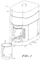
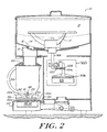
- Figs. 1 and 2 show a principal application of the present invention, namely, in a blender/shaver machine 10 adapted to the automatic manufacture of frozen drinks in bars and restaurants.
- a supply of ice in a hopper 12 is fed by a rotating set of blades 14 to a blade 16.
- the shaved ice falls through a chute 18 including a lid 20 into a blender cup 22 to which liquid ingredients such as a flavor concentrate and/or spirit have been added.
- Rotation of an impeller (or blade set) 24 at the bottom of the cup for a preset period of time produces a high quality frozen drink - - one that peaks when poured and has a generally uniform, non-marbled, non-watery consistency.
- the invention can be used in a wide variety of applications where it is desired to transmit power from a rotary output of a motive source (e.g., a motor) to a driven member under a load, particularly a rotating driven member held in a container that is sealed from and removable from the motive source.
- a motive source e.g., a motor
- the invention can be used, for example, in a variety of food processing equipment such as home blenders, food mixers, food processors and juicers.
- a magnetic drive 26 for the impeller 24 is the focus of the present invention.
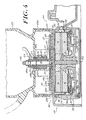
- the drive 26 includes a generally circular drive plate 34 rotatably mounted in the base 22a of the blender cup 22 and a brushless d.c. motor 28 including stator coils 30 and a rotor 32.
- the rotor in turn includes a double magnet assembly 35 preferably formed of a rotor ring magnet 36, a drive ring magnet 38 and a disc 40 of a magnetizable material, preferably cold-rolled steel, bonded between the magnets 36 and 38.
- the ring magnets 36 and 38 each have multiple circumferentially-arrayed, axially-directed poles 42, eight as shown in Fig. 6. Laterally adjacent segments have the opposite polarity. While eight poles are preferred, any even number can be used.
- each pole 42 is developed by a generally pie-shaped permanent magnet region 44 formed in a continuous ring of a strongly magnetic material such as the ceramic magnets sold by Hitachi Corporation.
- the magnet regions 44 in each magnet 36 and 38 can also be separate pieces bonded or otherwise mechanically secured to one another to form a ring assembly with flat faces and a generally cylindrical outer wall.
- a plastic hub 43 with radially directed support walls 43a fills the center of the magnets 36, 38 to facilitate mounting the assemblies on a central shaft.
- a north pole magnet region 44 is adjacent a south pole magnet region 44.
- Assemblies 36 and 38 are then affixed to the disc 40, preferably with each permanent magnet region 44 in one assembly overlying a like magnet region in the other assembly, but having the opposite polarity to avoid the repulsive magnetic force between the magnets 36 and 38.
- a plastic overlayer 48 helps to secure the sandwich assembly.
- the strength and this axial directing of the field of the drive magnet 38 induce magnetic fields of opposite polarity in a corresponding poles24a formed in the drive plate 34 despite the presence of a spacing 46, albeit a close spacing, between the generally flat upper surface 38a of the magnet assembly and the generally flat lower surface 34b of the plate 34.
- the permanent magnet 36 develops a magnet field strength of about 1400 gauss at its surface, and the spacing 46 is about 0.25 inch measured axially.
- This spacing includes, as shown in Fig. 4, not only four layers 48, 50a, 52, 22b of what is typically a plastic material, but also air gaps 54 and 56.
- Layers 48 and 52 are a thin plastic over-molding for the magnet assembly 35 and the drive plate 34, respectively.
- the layer 50a is the flat upper wall portion of a base 50 of the blender/shaver 10.
- Layer 22b is the flat lower wall of the cup base 22a.
- the air gap 54 is a slight clearance between the rotor over-molding 48 and the wall 50a.
- the gap 56 is a slight clearance between the wall 22b and the drive plate over-molding 52.
- this spacing is a significant source of reluctance in the magnet circuit between the ring drive magnet 38 and the plate 34.
- Permanent magnet rotors of known d.c. brushless motors e.g., the 5 inch disc-diameter motor sold by Integrated Motion Controls, LLC of Torrington, Connecticut under its Model No. 50, while roughly comparable in size, construction and field strength to the magnet 38, cannot couple to the plate 34 across the spacing 46 with sufficient strength to drive the disc operating a blender/ shaver.
- the motor 28 is mounted in the base 50 by screws 60 that pass through a steel motor cover 62 and a rear stator support 64 into threaded sockets 66 formed in a motor mount wall 50b of the base.
- the rear stator support 64 has a central opening that holds a bearing assembly 68 that journals a motor shaft 70. Screws (not shown) passing through openings 54a in the rear stator support thread into and secure a front stator support 72 to sandwich a ring 74 of back steel in the assembly adjacent the coils 30.
- the front stator support 72 has a periphery 72a that is sloped and slotted to carry the stator windings 30 as in the aforementioned Model 50 motor.
- the windings are three phase, being energized by a conventional brushless d.c. motor drive circuit to produce a rotating electromagnetic field.
- the base and stator supports are preferably formed of a moldable, high-strength plastic, and with a wall thickness, that rigidly supports the motor 28.
- the double magnet assembly 35 with the shaft 70 secured at its center slides axially into the bearing 68 (Fig. 4).
- the assembly 35 rotates in the bearing 68 with a clearance on all sides of the assembly 35.
- the multi-pole, d.c. magnetic field produced principally by the lower (as shown) rotor magnet 36 is directed principally downwardly to interact with the rotating electromagnetic field produced by the stator coils 30 when they are energized. Rotation of this electromagnetic field interacting with the rotor magnet assembly produces a torque that rotates the rotor at a like rotational speed.
- the disc 40 bonded between the magnets 36 and 38 transmits this torque to the plate drive magnet 38.
- a ring-like shroud 76 has a lower flange 76a that extends substantially across the air gap between the outer edge of the assembly 35 and the generally cylindrical inner side wall of the rear stator support 64 (with a slight clearance to avoid frictional contact with the magnet assembly 35). The shroud fills this gap sufficiently to impede an air flow that would otherwise feed oxygen to a fire.
- the magnet assembly 35 in a five-inch diameter weighs approximately three pounds. With typical operating speeds varying from 4,000 to 10,000 rpm, it can exert significant forces on the mounting structures, particularly rapidly varying forces that produce vibrations.
- the mounting structure is made sufficiently rigid, through choice and dimensions of materials as well as the overall design, e.g., the use of wall reinforcements such as exterior ribs, to resist the forces and moments produced in normal operation, and thereby to control vibrations that would otherwise loosen, wear and the extreme, eventually destroy the motor.
- Position of the rotor is sensed by three conventional Hall effect sensors mounted in a known manner in the motor housing, or the base 50. Position signals provide input to a known electronic control and drive circuit that energizes the three phase stator windings 30 to produce (i) a start-up torque, (ii) a ramp up of the rotor speed of rotation to a selected operating speed, (iii) a maintained rotation at that selected speed under load, and then (iv) a rapid and reliable braking. Operating of the motor is thus electronically controlled and programmable. Braking is electronic - - with the braking currents induced in the windings 30 being dissipated in large resistors or FET's mounted on heat sinks.
- the seal 84 retains liquid in the cup 22 despite the presence of a rotating shaft penetrating the bottom wall of the cup.
- the lower-most lip 84a engages the shaft 78 in a circumferential groove that locates and stabilizes the seal.
- a deep circular groove 84b in the lower face of the seal allows the lips to flex resiliently, yet lightly, against the shaft.
- an acorn nut 86 threaded on the upper end of the shaft 78 secures the blades 24 sandwiched between three washers 88a, 88b, and 88c.
- the drive plate 34 is part of a drive plate assembly that includes a set of vertical, radially-arrayed, reinforcing ribs 90 angularly centered over each pole 34a (Fig. 3).
- the ribs 90 and a central boss 91 that surrounds the shaft 78 are preferably molded continuously with the bottom layer 52.
- the plate 34 is preferably formed of a thin sheet of a ferrous material such as cold-rolled steel, e.g., 0.058 inch thick, with a set of open-ended radial slots 92 that produce the poles 34a.
- the slots 92 also control eddy currents induced in the plate by the rotating field of the drive magnet assembly 38.
- the attractive magnetic force acting on the drive plate 34 is preferably carried at a single, central pivot point formed by a hemispherical ball-bearing projecting from the bottom surface of the drive assembly and a stainless steel plate 96 mounted flush with the upper surface of the cup base wall 22b.
- This arrangement resists the magnet forces pulling down on the plate 34 while at the same time facilitating a low-friction, low-wear rotation of the shaft 78.
- the shaft 178 is rotatably supported by two axially spaced needle bearings 200a and 200b.
- a cylindrical spacer 202 is interposed between the needle bearings 200a and 200b and surrounds the shaft 178.
- the drive plate 134 is attached to the shaft 178 through a screw 206 having external threads for mating with complementary internal threads formed in the shaft 178.
- a flange 204 can be provided at the end of the shaft 178 and the drive plate 134 is sandwiched between the flange 204 and a washer 208 adjacent the head of screw 206.
- the coupling, or "traction” between the magnet 38 and the drive plate 34 increases not only as a function of the strength of the magnetic field acting on the poles 34a and the closeness of the magnet-to-disc spacing, but also as a function of the thinness of the plate 34 and the width of the slots 92.
- the thinner the plate and the wider the slots the more traction is produced for a given magnet and spacing.
- the presently preferred slot width for an eight-pole, 4.425 inches diameter plate is about 0.245 inch.
- stator coils 30 are preferably wound to optimize the torque output at a preselected operating speed, e.g., near 8,000 rpm.
- the drive plate assembly mainly a thin metal disc and plastic molding over it, are light and non-magnetic. There is little detectable gyroscopic effect when the cup is removed from the blender/ shaver after use. There is a low rotational momentum due to the impellers and drive plate assembly. Because the cup is light-weight and nonmagnetic, it is easy to handle.
- the magnetic drive 26 of the present invention allows the cup 22 to be placed in an operating position on the blender/shaver 10 with a simple, lateral sliding movement over the smooth, flat cup base 22b over the smooth, flat base portion 50a.
- the lateral sliding insertion and removal movements are not only more convenient, but they also reduces the vertical clearance required above the cup.
- This slide-in arrangement also facilitates cleaning the blender base - - one need only wipe a smooth surface. Spilled liquid and slush can flow or be pushed over the surface to a drain 94 formed in the base at the rear of the wall 50a.
- Figs. 2 , 8, and 9 illustrate a further application of the present invention, namely, in an ice shaver assembly for supplying shaved ice to the blender of the blender/shaver machine 10.
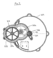
- the ice shaver assembly includes a magnetic drive and gear assembly 300 that operates to rotate blades 14 to supply shaved ice to the blender cup 22 through chute 16.
- the magnetic drive and gear assembly 300 is coupled to an output shaft 302 that is connected at its upper end to the rotating set of blades 14.
- the magnetic drive and gear assembly 300 includes a magnetic drive 304 that is analogous in structure and operation to the magnetic drive 26 of the blender.
- the output of the magnetic drive is transmitted through a gear assembly 306 to the output shaft 302 of the shaver.
- the gear assembly includes three gears, namely, a motor gear 328, a compound idler gear 332, and an output gear 334.
- the ring magnets 316 and 318 each have multiple circumferentially-arrayed, axially-directed poles, as in the case of the ring magnets 36 and 38 of the magnetic drive of the blender described above.
- the ring magnets 316 and 318 thus, have poles constructed and arranged in a manner analogous to the ring magnets 36 and 38 of the magnetic drive of the blender.
- a plastic hub 321 fills the center of the ring magnets 316 and 318 to facilitate mounting the magnets on a central shaft 322.
- the ring magnets are affixed to the disk 320, preferably with each pole in one ring magnet overlying a pole of the other ring magnet having the opposite polarity to avoid the repulsive magnetic force between the magnets 316 and 318.
- a plastic overlayer enclosing the magnets 316 and 318 and the disk 320 can help secure the magnet assembly.
- the brushless d.c. motor 310 is mounted in the motor housing 309 beneath the rotor 314.
- the motor 310 is constructed and operates in a manner analogous to the motor 28 of the magnetic drive 26 of the blender described above.
- the stator coils 312 are three phase coils being energized by a conventional brushless d.c. motor drive circuit to produce a rotating electromagnetic field.
- the rotor 314 with the shaft 322 secured at its center slides axially into a bearing 324.
- the rotor 314 rotates in the bearing 324 with clearance on all sides of the rotor 314.
- the position of the motor 314 can be sensed by three conventional Hall effect sensors mounted in the motor housing 309. Position signals provide input to an electronic control and drive circuit that energizes the three phase stator windings 312 to produce a startup torque, a rampup of the rotor speed of rotation to a selected operating speed, a maintained rotation at that selected speed under load, and a rapid and reliable braking torque.
- operation of the motor 310 thus can be electronic and programmable.
- Braking is electronic ⁇ with braking currents induced in the windings 312 being dissipated in large resistors or FET's mounted on heat sinks.
- the drive plate 308 can be structured in a manner analogous to the drive plate 34 of the magnetic drive 26 of the blender described above.
- the drive plate 308 is non-rotatably secured to the lower end of a drive shaft 326.
- the motor gear 328 is non-rotatably attached to a motor gear shaft 329 which in turn is attached to the upper end of the drive shaft 326.
- the motor gear 328 is preferably a helical gear having a plurality of helical gear teeth 350.
- the drive shaft 326 axially fits within the gear shaft 329 and is non-rotably secured to the gear shaft 329 and the gear 328 to permit the drive shaft 326 and the gear 328 to rotate in unison.
- rotational torque from the drive plate 308 can be transmitted to the gear 328 through the drive shaft 326.
- the drive shaft 326 and the gear shaft 329 of the motor gear 328 are rotatably supported by a pair of journal bearings 330a and 330a.
- the compound idler gear 332 is mechanically coupled to the motor gear 328 and the output gear 334 to transmit rotational torque from the motor gear 328 to the output gear 334.
- the idler gear 332 includes an elongated, cylindrically-shaped upper gear portion 332a having a plurality of helical gear teeth 352 and a generally disk-shaped lower gear portion 332b.
- the lower gear portion 332b is provided with a plurality of helical gear teeth 354 complementary in size and shape to the gear teeth 350 of the motor gear 328.
- the gear teeth 350 of the motor gear 328 engage the gear teeth 354 of the lower gear portion 332b to transmit rotational motion and torque from the motor gear 328 to the idler gear 332.
- the compound idler gear 332 is non-rotatably secured to a gear shaft 356 which is rotatably supported by a pair of journal bearings 333a and 333b.
- the output gear 334 is generally cylindrical in shape and is non-rotatably attached to the output shaft 302 to rotate with the output shaft 302.
- the output gear 334 is axially disposed over the output shaft 302 such that the output shaft is fitted within the central opening of the output gear 334.
- the output gear 334 is provided with a plurality of helical gear teeth 334a complementary in size and shape to the gear teeth 352 of the upper gear portion 332a of the idler gear 332.
- the gear teeth 352 of the upper gear portion 332a engage the gear teeth 334a of the output gear 334 to transmit rotational motion and torque from the idler gear 332 to the output gear 334.
- the output shaft 302 and the output gear 334 are rotatably supported by a pair of journal bearings 336a and 336b.
- the rotor gear 328, the idler gear 332, and the output gear 334 are preferably helical gears, having helically oriented gear teeth, constructed of light weight, high strength plastic material, such as acetyl or nylon.
- gear types such as spur gears, worm gears or combinations thereof, and other materials, such as metals or composites can be used in the gear assembly 306 of the present invention.
- the gear ratio of the gear assembly 306 of the present invention can be adjusted to increase or to decrease the rotational speed and torque transmitted from the drive shaft 326 of the magnetic drive 304 to the output shaft 302 of the ice shaver.
- the gear ratio of the gear assembly 306 can be adjusted to reduce the rotational speed, and thus increase the torque, transmitted from the drive shaft 326 to the output shaft 302.
- the rotational speed transmitted by the gear assembly 306 can be increased, thereby reducing the torque transmitted, by adjusting the gear ratio of the gear assembly 306.
- the gear ratio can be adjusted by changing the number of gear teeth, the number of gears, and/or the size of gears of the gear assembly, as known in the art.
- the desired speed of the output shaft 326 of the ice shaver is approximately 540 rpm for effective operation of the ice shaver.
- the magnetic drive 300 of the present invention employing a brushless d.c. motor as is preferred, typically generates an operational speed of approximately 6000 rpm. Accordingly, the gear ratio of the gear assembly 306 is approximately 11.1:1.
- magnétique drive and gear assembly of the present invention can be used in a wide variety of applications, in addition to the ice shaver described above, where it is desired to transmit power from a rotary output of a motor to a driven member under a load, including in other food processing equipment such as blenders, food mixers, food processors, and juicers.
- the ice shaver of the present invention is described as a component of a combination blender/ice shaver machine, one skilled in the art will readily appreciate that the ice shaver can be a stand alone unit, i.e., the ice shaver can be independent of the blender.
Landscapes
- Engineering & Computer Science (AREA)
- Food Science & Technology (AREA)
- Chemical & Material Sciences (AREA)
- Life Sciences & Earth Sciences (AREA)
- Polymers & Plastics (AREA)
- Power Engineering (AREA)
- Mechanical Engineering (AREA)
- Chemical Kinetics & Catalysis (AREA)
- Manufacturing & Machinery (AREA)
- Food-Manufacturing Devices (AREA)
- Dynamo-Electric Clutches, Dynamo-Electric Brakes (AREA)
- Mixers With Rotating Receptacles And Mixers With Vibration Mechanisms (AREA)
- General Preparation And Processing Of Foods (AREA)
- Mixers Of The Rotary Stirring Type (AREA)
- Combinations Of Kitchen Furniture (AREA)
- Brushes (AREA)
- Control Of Electric Motors In General (AREA)
- Meat, Egg Or Seafood Products (AREA)
- Connection Of Motors, Electrical Generators, Mechanical Devices, And The Like (AREA)
- Brushless Motors (AREA)
Abstract
Description
Claims (46)
- A drive (26) for rotating a driven member (24), said drive comprising:a drive plate (34) formed of magnetizable material coupled to said driven member (24) to rotate therewith,a motor (28) positioned proximate said drive plate (34) said motor having a stator (30) and a rotor (32), said rotor (32) including a rotor magnet (36), said stator (30) producing an electromagnetic field that interacts with said rotor magnet (36) to rotate said rotor magnet (36), anda drive magnet (38) coupled to said rotor magnet (36) to rotate therewith, said drive magnet (38) inducing a magnetic field in a direction toward said drive plate (34) to transmit a drive torque from said motor (28) to said drive plate (34) to rotate said driven member (24).
- The drive of Claim I, wherein said motor (28) is an electric motor.
- The drive of Claim 2, wherein said electric motor (28) is a brushless d.c. motor.
- The drive of any preceding claim, wherein said drive magnet (38) and said rotor magnet (36) each include a plurality of poles (42).
- The drive of Claim 4, wherein said drive magnet (38) and said rotor magnet (36) have a like number of poles (42).
- The drive of Claim 5, wherein said poles (42) of said drive magnet (38) are aligned by pole polarity with said poles (42) of said rotor magnet (36).
- The drive of any of claims 4 to 6, wherein said poles (42) of said drive magnet (38) and said poles (42) of said rotor magnet (36) are circumferentially-aligned.
- The drive of any of claims 4 to 7, wherein said drive plate (34) includes a plurality of radial directed open slots (92) that define a plurality of poles (34a) on said drive plate (34).
- The drive of Claim 8, wherein said drive plate (34) and said drive magnet (38) have a like number of poles, said poles (34a) of said drive plate (34) being aligned with said poles (42) of said drive magnet (38).
- The drive of Claim 9, wherein said drive plate (34) is formed of cold-rolled steel.
- The drive of Claim 8, wherein said drive plate (34), said drive magnet (38), and said rotor magnet (36) each have eight poles.
- The drive of any preceding claim, wherein said drive magnet (38) and said rotor magnet (36) are centered on a common axis of rotation.
- The drive of Claim 12, wherein said common axis is coaxially aligned with the axis of rotation of said drive plate (34).
- The drive of any preceding claim, further comprising a plate (40) of magnetizable material secured between said drive magnet (38) and said rotor magnet (36).
- The drive of Claim 14, wherein said rotor magnet (36), said drive magnet (38), and said plate (40) are enclosed within a layer of a plastic material (48).
- The drive of any preceding claim, further comprising a first housing (22a) enclosing said drive plate (34) and a second housing (50) enclosing said motor (28), said rotor magnet (36), and said drive magnet (38), and wherein said drive plate (34) is rotably mounted in said first housing (22a) in a closely spaced (46), axially aligned relationship with said drive magnet (38).
- The drive of Claim 16, wherein said close spacing (46) accommodates (i) an upper wall (50a) of said second housing (50), (ii) a lower wall (22b) of said first housing (22a), (iii) an air gap (56) between said lower wall (22b) and said drive plate (34), and (iv) an air gap (54) between said upper (50a) wall and said drive magnet (38).
- The drive of Claim 16, wherein said drive magnet (38) has a field strength of about 1400 gauss at its surface and said close spacing (46), measured axially, is about 6.35mm (0.25 inch)
- The drive of any preceding claim, wherein said motor (28) and drive magnet (38) have a maximum height-to-width ratio of about 1:3, where height is measured along the axis of rotation of said motor (28) and said drive magnet (38).
- The drive of any preceding claim, wherein said motor (28) includes an output shaft (70) secured to said rotor (32) and rotatable within said stator (30) in bearings (68), a rear stator support (64) that supports said bearings (68) at its center and has rigid, generally cylindrical side walls surrounding said stator (30) and said rotor (32) with a gap, and a shroud (76) that spans said gap.
- The drive of any preceding claim, wherein said rotor magnet (36) and drive magnet (38) each are a single ring magnet.
- The drive of any preceding claim, wherein said driven member (24) is a shaft (78) of a food processing apparatus.
- The drive of Claim 22, wherein said food processing apparatus is a blender, an ice shaver, a food mixer, a food processor, or a juicer.
- The drive of Claim 22, wherein said food processing apparatus includes a receptacle (22) for receiving food for processing, said receptacle having a rotatable element (24) mounted on said shaft (78).
- The drive of Claim 24, further comprising a seal (84) positioned about said shaft (78) to provide a fluid seal between said receptacle (22) and said shaft (78).
- The drive of Claim 24, wherein said rotatable element (24) is a blade for processing food.
- The drive of any preceding claim, further comprising a gear assembly (306) including one or more gears (328, 332, 334) coupled to said drive plate (308) and to said driven member (14), said gear assembly (306) transmitting said drive torque from said drive plate (308) to said driven member (14).
- The drive of Claim 27, wherein the gear assembly (306) increases the drive torque transmitted from said drive plate (308) to said driven member (14).
- The drive of Claim 27, wherein the gear assembly (306) decreases the drive torque transmitted from said drive plate (308) to said driven member (14).
- The drive of Claim 27, wherein said drive plate (308) is secured to a drive shaft (326) to rotate with said drive shaft (326).
- The drive of Claim 30, wherein said drive magnet (318) and said rotor magnet (316) are centered on a common axis of rotation.
- The drive of Claim 31, wherein said common axis is coaxially aligned with said drive shaft (326).
- The drive of Claim 32, wherein said driven member (14) rotates about an axis of rotation offset from said common axis of rotation.
- The drive of Claim 30, wherein a first gear (328) of said gear assembly (306) is secured to said drive shaft (326) to rotate therewith.
- The drive of Claim 34, wherein a second gear (334) of said gear assembly (306) is coupled to said driven member (14) to rotate therewith, said first gear (328) and second gear (334) interacting to transmit said drive torque from said drive plate (308) to said driven member (14).
- The drive of Claim 35 wherein said gear assembly (306) further comprises a third gear (332) interposed between said first gear (328) and said second gear (334), and said third gear (332) interacting with said first gear (328) and said second gear (334) to transmit said drive torque therebetween.
- The drive of any preceding claim, further comprising a control and drive unit electrically coupled to said motor (28) to control operation of said motor (28), said control and drive unit selectively energizing said stator (30) to produce an operating torque or a braking torque on said rotor (32).
- The drive of Claim 37, wherein said stator (30) includes one or more stator coils.
- The drive of Claim 38, wherein said control and drive unit varies current through said stator coils to produce said operating torque or said braking torque.
- The drive of Claim 37, further comprising one or more position sensors coupled to said control and drive unit to monitor the location of said rotor (32).
- The drive of Claim 40, wherein the position sensors are Hall effect sensors.
- A method of operating a food processing apparatus, the food processing apparatus including a food receptacle (22) having a rotating element (24) mounted on a shaft (78), a drive plate (34) formed of magnetizable material secured to said shaft (78) to rotate therewith, and a magnet assembly (36,38) magnetically coupled to a motor (28) and said drive plate (34), the method comprising the steps of:transmitting an operating torque at an operating speed from said motor (28) to said drive plate (34) through said magnet (36, 38) assembly to effect rotation of said shaft (78) and said rotating element (24), andtransmitting a braking torque from said motor (28) to said drive (34) plate through said magnet assembly (36, 38) to terminate rotation of said shaft (78) and said rotating element (24).
- The method of Claim 42, wherein said operating torque and said braking torque are transmitted from said motor (28) to said drive plate (34) without mechanical coupling of said drive plate (34) to said motor (28).
- The method of Claim 42, wherein the step of transmitting an operating torque comprisestransmitting a start-up torque from said motor (28) to said drive plate (34),increasing the speed of rotation of said drive plate (34) to said operating speed, andmaintaining said operating speed at said operating torque.
- The method of Claim 42, wherein the motor (28) is a brushless d.c. motor having one or more stator coils (30) and wherein said operating torque and said braking torque are generated by varying current through said stator coils (30).
- A food processing apparatus comprising:a blender comprisinga blender cup (22) having a first blade (24) rotatably mounted on a first shaft (78),a first drive (34) plate formed of magnetizable material secured to said first shaft (78) to rotate therewith,a first motor (28) positioned proximate said first drive plate (34), said first motor (28) having a first stator (30) and a first rotor (32), said first rotor (30) including a first rotor magnet (36), said first stator (30) producing an electromagnetic field that interacts with said first rotor magnet (36) to rotate said first rotor magnet (36),a first drive magnet (38) coupled to said first rotor magnet (36) to rotate therewith, said first drive magnet (38) inducing a magnetic field in a direction towards said first drive plate (34) to transmit a drive torque from said first motor (28) to said first drive (34) plate thereby rotating said first shaft (78) and said first blade (24); andan ice shaver for supplying shaved ice to said blender, said ice shaver comprisingan ice hopper (12) having a second blade (14) rotatably mounted on a second shaft (302), and said ice hopper (12) including a chute (16) connected to said blender cup (22) for supplying shaved ice to said blender cup (22),a second drive plate (308) formed of magnetizable material,a second motor (310) positioned proximate said second drive plate (308), said second motor (310) having a second stator (312) and a second rotor (314), said second rotor (314) including a second rotor magnet (316), said second stator (312) producing an electromagnetic field that interacts with said second rotor magnet (314) to rotate said second rotor magnet (316).a second drive magnet (318) coupled to said second rotor magnet (316) to rotate therewith, said second drive magnet (318) inducing a magnetic field in a direction toward said second drive plate (308) to transmit torque from said second motor (310) to said second drive plate (308), anda gear assembly (306) including one or more gears (328, 332, 334) coupled to said second drive plate (308) and to said second shaft (302), said gear assembly (306) transmitting said drive torque from said second drive plate (308) to said second shaft (302) to effect shaving of said ice with said second blade (14).
Applications Claiming Priority (5)
| Application Number | Priority Date | Filing Date | Title |
|---|---|---|---|
| US228377 | 1981-01-26 | ||
| US09/228,377 US6095677A (en) | 1999-01-12 | 1999-01-12 | Magnetic drive blender |
| US09/473,311 US6210033B1 (en) | 1999-01-12 | 1999-12-28 | Magnetic drive blender |
| US473311 | 1999-12-28 | ||
| PCT/US2000/000668 WO2000041607A1 (en) | 1999-01-12 | 2000-01-11 | Food processing apparatus including magnetic drive |
Publications (2)
| Publication Number | Publication Date |
|---|---|
| EP1139837A1 EP1139837A1 (en) | 2001-10-10 |
| EP1139837B1 true EP1139837B1 (en) | 2002-12-04 |
Family
ID=26922314
Family Applications (1)
| Application Number | Title | Priority Date | Filing Date |
|---|---|---|---|
| EP00906896A Expired - Lifetime EP1139837B1 (en) | 1999-01-12 | 2000-01-11 | Food processing apparatus including magnetic drive |
Country Status (14)
| Country | Link |
|---|---|
| US (3) | US6336603B1 (en) |
| EP (1) | EP1139837B1 (en) |
| JP (1) | JP2002534953A (en) |
| CN (1) | CN1140222C (en) |
| AT (1) | ATE228797T1 (en) |
| AU (1) | AU766339B2 (en) |
| BR (1) | BR0007482B1 (en) |
| CA (1) | CA2360525C (en) |
| DE (1) | DE60000913T2 (en) |
| ES (1) | ES2188508T3 (en) |
| ID (1) | ID29872A (en) |
| MX (1) | MXPA01007055A (en) |
| NZ (1) | NZ513327A (en) |
| WO (1) | WO2000041607A1 (en) |
Cited By (5)
| Publication number | Priority date | Publication date | Assignee | Title |
|---|---|---|---|---|
| US6776087B1 (en) | 2003-06-25 | 2004-08-17 | The Amstad Family Revocable Trust | Food processing machine |
| US10213756B2 (en) | 2013-10-25 | 2019-02-26 | Whirlpool Corporation | Magnetic disc coupler |
| US11420814B2 (en) * | 2018-08-17 | 2022-08-23 | Coldsnap, Corp. | Rapidly cooling food and drinks |
| US11565874B2 (en) | 2016-06-16 | 2023-01-31 | Coldsnap, Corp. | System for providing a single serving of a frozen confection |
| US11846466B2 (en) | 2018-08-17 | 2023-12-19 | Coldsnap, Corp. | Rapidly cooling food and drinks |
Families Citing this family (128)
| Publication number | Priority date | Publication date | Assignee | Title |
|---|---|---|---|---|
| US6793167B2 (en) * | 1999-01-12 | 2004-09-21 | Island Oasis Cocktail Company, Inc. | Food processing apparatus including magnetic drive |
| PT1392441E (en) * | 2001-06-05 | 2008-09-30 | Elan Pharma Int Ltd | System and method for milling materials |
| US6719227B2 (en) * | 2001-11-16 | 2004-04-13 | General Electric Canada Inc. | Grinding mill and methods for fabricating same |
| US20040099076A1 (en) * | 2002-07-25 | 2004-05-27 | Igor Haskin | Gear motor assembly |
| DE10253072A1 (en) * | 2002-11-07 | 2004-05-27 | Brose Fahrzeugteile Gmbh & Co. Kg, Coburg | Component with coils forming part of e.g. permanent magnet motor drive for vehicle actuator, has carrier with radially-projecting bridges and insertion sections for coils |
| DE10260040A1 (en) * | 2002-12-19 | 2004-07-15 | Braun Gmbh | mixing device |
| US6962433B2 (en) * | 2003-01-30 | 2005-11-08 | Scientific Industries, Inc. | Magnetic stirring apparatus having low rotational speeds |
| US7075040B2 (en) * | 2003-08-21 | 2006-07-11 | Barnstead/Thermolyne Corporation | Stirring hot plate |
| US6959562B2 (en) * | 2003-12-15 | 2005-11-01 | The Coleman Company, Inc. | Portable frozen drink machine |
| US8474369B2 (en) * | 2004-11-26 | 2013-07-02 | Walter B. Herbst | Electric skillet with magnetic self-reversing stirrer that is removable |
| US20060146645A1 (en) * | 2005-01-06 | 2006-07-06 | Rosener William J | MagnaStir |
| US20060172041A1 (en) * | 2005-01-28 | 2006-08-03 | Farrell Patrick L | Magnetic aerator |
| CN2902146Y (en) * | 2006-01-17 | 2007-05-23 | 蔡应麟 | Electric agitating cup |
| DE102006025307A1 (en) * | 2006-05-31 | 2007-12-06 | Vorwerk & Co. Interholding Gmbh | Method for fixing ball bearings and built-in part, for example, a food processor with a shaft |
| DE102007005110B4 (en) * | 2007-02-01 | 2009-07-02 | BSH Bosch und Siemens Hausgeräte GmbH | Food processor with intermediate gear |
| GB2457682B (en) * | 2008-02-21 | 2012-03-28 | Magnomatics Ltd | Variable magnetic gears |
| CN101485541B (en) * | 2009-01-09 | 2011-04-13 | 蔡坚明 | Cup for heating, stirring and foaming fluid food |
| CA2653581A1 (en) | 2009-02-11 | 2010-08-11 | Kenneth Scott Alexander Butcher | Migration and plasma enhanced chemical vapour deposition |
| US8282268B2 (en) * | 2009-02-24 | 2012-10-09 | Island Oasis Frozen Cocktail Co., Inc. | Magnetic drive for food processing apparatus |
| US20100282099A1 (en) * | 2009-05-08 | 2010-11-11 | Lahav Gil | Magnetic Homogenizer Apparatus |
| US8550388B2 (en) | 2010-03-15 | 2013-10-08 | Moog Inc. | Drive circuit with integrated power factor correction for blender/shaver machine |
| CN102255402B (en) | 2010-05-20 | 2016-01-20 | 德昌电机(深圳)有限公司 | Household electrical appliance |
| CN101947074B (en) * | 2010-09-09 | 2012-10-03 | 揭阳市百年家电实业有限公司 | Chocolate rotator |
| FR2967340B1 (en) * | 2010-11-16 | 2013-01-04 | Seb Sa | WORKING CONTAINER FOR CULINARY PREPARATION ELECTRICAL APPLIANCES |
| US9084512B2 (en) * | 2011-05-16 | 2015-07-21 | Vita-Mix Management Corporation | Blender base |
| US9010668B2 (en) * | 2011-06-30 | 2015-04-21 | Sammic, S.L. | Safety device for food cutting machine |
| US20130043337A1 (en) * | 2011-08-15 | 2013-02-21 | Steve Rukavina | Apparatus for controlling the blending of drinks |
| US10455848B2 (en) * | 2011-10-05 | 2019-10-29 | Island Oasis Frozen Cocktail Company, Inc. | Individual frozen drink dispenser |
| US8939389B2 (en) | 2012-03-07 | 2015-01-27 | Snowie LLC | Block ice shaver |
| US12253291B2 (en) | 2012-03-07 | 2025-03-18 | Snowie LLC | Block ice shaver with tension arm and shaping device |
| US10378807B2 (en) | 2012-03-07 | 2019-08-13 | Snowie LLC | Block ice shaver with tension arm and shaping device |
| CN202537098U (en) * | 2012-03-23 | 2012-11-21 | 永庆国际有限公司 | Food processor with safety protection mechanism |
| US9867387B2 (en) * | 2012-08-16 | 2018-01-16 | Sunbeam Products, Inc. | Frozen beverage blending and dispensing appliance |
| CN103843963A (en) * | 2012-12-05 | 2014-06-11 | 中山东菱威力电器有限公司 | Hardness monitoring system of ice cream machine |
| US20150367302A1 (en) * | 2013-01-23 | 2015-12-24 | Ge Healthcare Bio-Sciences Ab | Magnetic agitator mixing system and an agitator mixing stand |
| US20140212566A1 (en) * | 2013-01-30 | 2014-07-31 | Island Oasis Frozen Cocktail Co., Inc. | Frozen drink dispenser and method of dispensing frozen drinks |
| WO2014134600A1 (en) | 2013-03-01 | 2014-09-04 | Vita-Mix Corporation | Blending system |
| US9855535B2 (en) | 2013-03-01 | 2018-01-02 | Vita-Mix Management Corporation | Blending system |
| CN105050464B (en) * | 2013-03-15 | 2018-01-05 | 穆格公司 | Mixer motor case |
| US9167938B2 (en) * | 2013-03-15 | 2015-10-27 | Whirlpool Corporation | Food processor mixer attachment |
| EP2777455B1 (en) | 2013-03-15 | 2016-01-06 | Whirlpool Corporation | Low profile side drive blending appliance |
| WO2014201509A2 (en) * | 2013-06-19 | 2014-12-24 | Breville Pty Limited | Improved cooking apparatus and method |
| DE102014113891A1 (en) * | 2013-10-18 | 2015-04-23 | Vorwerk & Co. Interholding Gmbh | Electric motor driven food processor |
| US10443916B2 (en) | 2013-10-21 | 2019-10-15 | Snowie LLC | Portable frozen confection machine |
| US10794624B2 (en) | 2013-10-21 | 2020-10-06 | Snowie LLC | Portable frozen confection machine |
| US20150117139A1 (en) * | 2013-10-25 | 2015-04-30 | Whirlpool Corporation | Blender jar assembly |
| US9555384B2 (en) * | 2013-10-25 | 2017-01-31 | Whirlpool Corporation | Blender assembly |
| CN203647174U (en) * | 2013-12-31 | 2014-06-18 | 李文钦 | A stirring cooking machine with heating function under the stirring |
| JP2015156994A (en) * | 2014-02-25 | 2015-09-03 | パナソニックIpマネジメント株式会社 | Agitator, container with agitation function, and heating and agitating cooker |
| US9883772B2 (en) | 2014-03-13 | 2018-02-06 | Whirlpool Corporation | Magnetic disk coupler for blending apparatus with energy storage |
| US9763542B2 (en) | 2014-03-13 | 2017-09-19 | Whirlpool Corporation | Anti-rotational latch for a blending appliance |
| USD771999S1 (en) | 2014-03-14 | 2016-11-22 | Vita-Mix Management Corporation | Blender base |
| CN103846135B (en) * | 2014-03-17 | 2016-06-29 | 占行波 | Iron content iron powder powder extractor |
| US10092139B2 (en) | 2014-04-28 | 2018-10-09 | Whirlpool Corporation | Low profile motor for portable appliances |
| CN107427797B (en) | 2015-02-17 | 2021-08-03 | 维他拌管理有限公司 | Interlocking Mixing System |
| US11253106B2 (en) | 2015-04-24 | 2022-02-22 | Vita-Mix Management Corporation | Interlocking blending system |
| US10413131B2 (en) | 2015-04-24 | 2019-09-17 | Vita-Mix Management Corporation | Interlocking blending system |
| DE102015009895B4 (en) * | 2015-07-30 | 2019-08-14 | Sartorius Stedim Biotech Gmbh | Mixing system, mixing device, container and method for mixing a fluid and / or a solid |
| US10390648B1 (en) * | 2015-12-15 | 2019-08-27 | Grindmaster Corporation | Virtual sight glass for a portable beverage dispensing container |
| JP6541245B2 (en) * | 2016-02-05 | 2019-07-10 | コーニンクレッカ フィリップス エヌ ヴェKoninklijke Philips N.V. | Safety bearing mechanism and food processing device |
| US11097236B2 (en) | 2016-03-31 | 2021-08-24 | Global Life Sciences Solutions Usa Llc | Magnetic mixers |
| US10335750B2 (en) * | 2016-03-31 | 2019-07-02 | General Electric Company | Magnetic drive for bioreactor |
| EP3251566A3 (en) * | 2016-04-13 | 2018-03-07 | Vita-Mix Management Corporation | Auxiliary cooling fan for a blending system |
| CN105747918A (en) * | 2016-04-27 | 2016-07-13 | 浙江祥晖数码科技有限公司 | Novel automatic rotating type wine decanter |
| US10582801B2 (en) * | 2016-05-11 | 2020-03-10 | Island Oasis Frozen Cocktail Company, Inc. | Beverage preparation system |
| US10471439B2 (en) | 2016-05-17 | 2019-11-12 | Heathrow Scientific Llc | Combination centrifuge and magnetic stirrer |
| US11033153B2 (en) | 2016-06-10 | 2021-06-15 | Vita-Mix Management Corporation | Drive coupler for blender |
| US10426180B1 (en) | 2016-06-16 | 2019-10-01 | Sigma Phase, Corp. | System for providing a single serving of a frozen confection |
| KR102162237B1 (en) * | 2016-08-19 | 2020-10-06 | 광동 메이디 컨슈머 일렉트릭스 매뉴팩쳐링 컴퍼니 리미티드 | Blade holder assembly, mixing cup assembly and food processor |
| CN107773070B (en) * | 2016-08-31 | 2023-11-28 | 刘金明 | Bidirectional stirrer |
| DE102016011266B4 (en) * | 2016-09-17 | 2020-01-16 | Ika-Werke Gmbh & Co. Kg | Device for crushing or grinding and a method for sealing such a device |
| CN106388619B (en) * | 2016-10-08 | 2019-12-17 | 佛山市顺德区美的电热电器制造有限公司 | Upper cover with stirring function and electric cooking appliance |
| US11412893B2 (en) | 2016-11-01 | 2022-08-16 | Vita-Mix Management Corporation | Blending volume reducing device |
| LT6541B (en) * | 2016-12-05 | 2018-07-10 | UAB "Millo Appliances" | FOOD AND BEVERAGE PROCESSING EQUIPMENT WITH MAGNETINE HANDLE |
| WO2018108807A1 (en) | 2016-12-13 | 2018-06-21 | Nestec Sa | High torque magnetic transmission for whisk |
| CN108309090A (en) * | 2017-01-16 | 2018-07-24 | 广东美的生活电器制造有限公司 | Food cooking machine |
| US11478766B2 (en) | 2017-06-30 | 2022-10-25 | Vita-Mix Management Corporation | Intelligent blending system |
| CN109419397B (en) * | 2017-08-31 | 2021-09-24 | 佛山市顺德区美的电热电器制造有限公司 | Magnetic disc assembly, stirring cutter and food processor |
| CN109419396B (en) * | 2017-08-31 | 2021-08-31 | 佛山市顺德区美的电热电器制造有限公司 | Stirring knife assembly, stirring cup assembly and food processor |
| WO2019071389A1 (en) * | 2017-10-09 | 2019-04-18 | Face Moore International Limited | Mixing device |
| FR3072268B1 (en) * | 2017-10-13 | 2019-12-06 | Beaba | BLADE HOLDER FOR KITCHEN HOUSEHOLD ROBOT |
| US10881135B1 (en) | 2017-11-10 | 2021-01-05 | Creative Destruction, LLC | Cyclonically cooled and filtered smoking water pipe and method |
| ES2820549T3 (en) * | 2018-02-21 | 2021-04-21 | Vorwerk Co Interholding | Food preparation device with locking mechanism |
| CN110393461A (en) * | 2018-04-24 | 2019-11-01 | 主力智业(深圳)电器实业有限公司 | A magnetic drive silent mixer |
| CN108759218B (en) * | 2018-05-21 | 2020-11-20 | 海尔智家股份有限公司 | Ice crusher and refrigerator |
| CN108800694B (en) * | 2018-05-21 | 2021-03-23 | 海尔智家股份有限公司 | Ice crushing device and refrigerator |
| CN108759217B (en) * | 2018-05-21 | 2021-04-23 | 海尔智家股份有限公司 | Ice crusher and refrigerator |
| CN108759216B (en) * | 2018-05-21 | 2020-11-20 | 海尔智家股份有限公司 | Ice crusher and refrigerator |
| CN108662821B (en) * | 2018-05-21 | 2020-11-20 | 海尔智家股份有限公司 | Ice crusher and refrigerator |
| US11470855B2 (en) | 2018-08-17 | 2022-10-18 | Coldsnap, Corp. | Providing single servings of cooled foods and drinks |
| CN109512128B (en) * | 2018-11-06 | 2024-04-02 | 惠东县港东塑胶制品有限公司 | Self-stirring coffee cup |
| CN112401693B (en) * | 2019-08-23 | 2024-06-11 | 广东美的生活电器制造有限公司 | Food processor |
| WO2021055877A1 (en) * | 2019-09-19 | 2021-03-25 | Sigma Phase, Corp. | Rapidly cooling food and drinks |
| US11330938B2 (en) * | 2019-11-06 | 2022-05-17 | Whirlpool Corporation | Non-contact magnetic coupler for food processing appliance having small brushless permanent magnet motor |
| US11337438B2 (en) | 2020-01-15 | 2022-05-24 | Coldsnap, Corp. | Rapidly cooling food and drinks |
| USD927923S1 (en) | 2020-03-20 | 2021-08-17 | Vita-Mix Management Corporation | Blender base |
| CN111495300A (en) * | 2020-04-28 | 2020-08-07 | 北京阳光凯特科技有限公司 | Illumination parallel reaction device |
| TW202202790A (en) | 2020-06-01 | 2022-01-16 | 美商寇德斯納普公司 | Refrigeration systems for rapidly cooling food and drinks |
| CN111839270B (en) * | 2020-07-31 | 2021-08-10 | 耶加雪菲咖啡(深圳)有限公司 | Manual and electric grinding integrated device for coffee machine |
| CN112076874B (en) * | 2020-08-31 | 2021-12-03 | 澳润(山东)药业有限公司 | A traditional Chinese medicine heating and stirring device based on voice control |
| ES2908744A1 (en) * | 2020-10-30 | 2022-05-03 | Cecotec Res And Development Sl | Electrical food preparation apparatus with axial magnetic flux engine (Machine-translation by Google Translate, not legally binding) |
| CN113040625B (en) * | 2020-12-09 | 2022-11-01 | 浙江绍兴苏泊尔生活电器有限公司 | Food processor |
| US11827402B2 (en) | 2021-02-02 | 2023-11-28 | Coldsnap, Corp. | Filling aluminum cans aseptically |
| WO2022225785A1 (en) * | 2021-04-21 | 2022-10-27 | Amgen Inc. | Magnetic drive extension for use with virus inactivation skid |
| CN119403454A (en) | 2022-05-13 | 2025-02-07 | 尚科宁家运营有限公司 | Agitators for carbonation systems |
| US12096880B2 (en) | 2022-05-13 | 2024-09-24 | Sharkninja Operating Llc | Flavorant for beverage carbonation system |
| US12213617B2 (en) | 2022-05-13 | 2025-02-04 | Sharkninja Operating Llc | Flavored beverage carbonation process |
| US11647860B1 (en) | 2022-05-13 | 2023-05-16 | Sharkninja Operating Llc | Flavored beverage carbonation system |
| US11751585B1 (en) | 2022-05-13 | 2023-09-12 | Sharkninja Operating Llc | Flavored beverage carbonation system |
| US12005404B2 (en) | 2022-08-22 | 2024-06-11 | Sharkninja Operating Llc | Beverage carbonation system flow control |
| US12539500B2 (en) | 2022-08-31 | 2026-02-03 | Sharkninja Operating Llc | Additive containers |
| CN116172423B (en) * | 2022-10-26 | 2024-08-23 | 浙江绍兴苏泊尔生活电器有限公司 | Food processor |
| US12084334B2 (en) | 2022-11-17 | 2024-09-10 | Sharkninja Operating Llc | Ingredient container |
| US12103840B2 (en) | 2022-11-17 | 2024-10-01 | Sharkninja Operating Llc | Ingredient container with sealing valve |
| US11738988B1 (en) | 2022-11-17 | 2023-08-29 | Sharkninja Operating Llc | Ingredient container valve control |
| US11634314B1 (en) | 2022-11-17 | 2023-04-25 | Sharkninja Operating Llc | Dosing accuracy |
| US11745996B1 (en) | 2022-11-17 | 2023-09-05 | Sharkninja Operating Llc | Ingredient containers for use with beverage dispensers |
| USD1091308S1 (en) | 2022-12-23 | 2025-09-02 | Sharkninja Operating Llc | Ingredient container |
| USD1092208S1 (en) | 2022-12-23 | 2025-09-09 | Sharkninja Operating Llc | Cap of ingredient container |
| CN115989962A (en) * | 2023-01-17 | 2023-04-21 | 纯米科技(上海)股份有限公司 | Food processor |
| US11871867B1 (en) | 2023-03-22 | 2024-01-16 | Sharkninja Operating Llc | Additive container with bottom cover |
| US12116257B1 (en) | 2023-03-22 | 2024-10-15 | Sharkninja Operating Llc | Adapter for beverage dispenser |
| US11925287B1 (en) | 2023-03-22 | 2024-03-12 | Sharkninja Operating Llc | Additive container with inlet tube |
| US12005408B1 (en) | 2023-04-14 | 2024-06-11 | Sharkninja Operating Llc | Mixing funnel |
| CN116865515B (en) * | 2023-06-07 | 2024-04-26 | 米拌(上海)科技有限公司 | Magnetic force output motor and magnetic stirring container using same |
| WO2024254837A1 (en) | 2023-06-16 | 2024-12-19 | Sharkninja Operating Llc | Carbonation mixing nozzles |
| CN116722711B (en) * | 2023-06-16 | 2024-05-10 | 宁波苏智美电机科技有限公司 | Universal direct drive motor device |
| US12471739B1 (en) * | 2025-08-21 | 2025-11-18 | Sheila Mosley | Countertop appliance with integrated ice dispenser and dual mixing mechanisms |
Family Cites Families (40)
| Publication number | Priority date | Publication date | Assignee | Title |
|---|---|---|---|---|
| US1242493A (en) | 1917-01-12 | 1917-10-09 | Richard H Stringham | Electrical drink-mixer. |
| US1420773A (en) | 1921-12-22 | 1922-06-27 | Magnetic Drink Mixer Company | Electrical drink mixer |
| US1420774A (en) | 1921-12-22 | 1922-06-27 | Magnetic Drink Mixer Company | Electrical drink mixer |
| US2356784A (en) | 1942-04-07 | 1944-08-29 | Maurice H Graham | Coffee pot |
| US2350534A (en) | 1942-10-05 | 1944-06-06 | Rosinger Arthur | Magnetic stirrer |
| GB622115A (en) | 1945-09-18 | 1949-04-27 | Gen Mills Inc | Improvements in or relating to rotary mixers driven by electric power |
| US2549121A (en) | 1946-07-08 | 1951-04-17 | Mcgraw Electric Co | Mixer |
| US2459224A (en) | 1946-08-17 | 1949-01-18 | William L Hendricks | Magnetically operated stirrer for mixing liquids |
| US2466468A (en) | 1946-12-23 | 1949-04-05 | Neal Harry Herbert | Magnetic mixer |
| US2655011A (en) | 1948-12-06 | 1953-10-13 | Ihle | Combined container and dispenser for liquids |
| US2566743A (en) | 1949-10-24 | 1951-09-04 | Okulitch George Joseph | Magnetic drive agitator |
| US2828950A (en) | 1957-03-13 | 1958-04-01 | Ralph M Stilwell | Liquid stirring and dispensing mechanism |
| US2951689A (en) | 1958-03-24 | 1960-09-06 | Halogen Insulator And Seal Cor | Magnetic stirring bar |
| US3113228A (en) | 1959-03-27 | 1963-12-03 | Manuel J Tolegian | Magnetic coupling and applications thereof |
| US3140079A (en) | 1960-02-18 | 1964-07-07 | Baermann Max | Magnetic drive |
| DE1131372B (en) * | 1960-05-19 | 1962-06-14 | Siemens Elektrogeraete Gmbh | Kitchen machine |
| US3279765A (en) | 1964-03-03 | 1966-10-18 | Kk | Liquid agitating device |
| US3304990A (en) | 1965-02-15 | 1967-02-21 | Univ Tennessee Res Corp | Explosion proof centrifugal evaporator with magnetic drive |
| FR1570922A (en) | 1967-06-22 | 1969-06-13 | ||
| US3694341A (en) | 1971-01-27 | 1972-09-26 | William R Luck Jr | Metal recovery device |
| US3680984A (en) | 1971-07-23 | 1972-08-01 | Westinghouse Electric Corp | Compressor combined flexible and magnetic drive coupling |
| US3920163A (en) | 1973-07-11 | 1975-11-18 | Jet Spray Cooler Inc | Beverage dispenser with in-bowl whipper |
| US4199265A (en) | 1978-10-30 | 1980-04-22 | American Hospital Supply Corporation | Motorless magnetically coupled stirrer |
| US4226669A (en) | 1979-05-09 | 1980-10-07 | Savant Instruments, Inc. | Vacuum centrifuge with magnetic drive |
| EP0052324B1 (en) | 1980-11-17 | 1986-03-05 | Helmut Dipl.-Ing. Herz | Magnetic mixer |
| JPS6034727A (en) | 1983-08-05 | 1985-02-22 | S R D Kk | Electromagnetic induction agitator |
| CH668919A5 (en) | 1984-05-07 | 1989-02-15 | Dieter Alex Rufer | DEVICE FOR STIRING OR PUMPING A MEDIUM. |
| US4780637A (en) | 1985-12-20 | 1988-10-25 | Eaton Corporation | Brushless eddy current coupling - stationary field |
| DE3640397C1 (en) * | 1986-11-26 | 1988-01-07 | Philips Patentverwaltung | Drive device for a small household appliance |
| US4913555A (en) | 1987-01-14 | 1990-04-03 | Sanyo Electric Co., Ltd. | Whipping machine |
| US4836826A (en) | 1987-12-18 | 1989-06-06 | The United States Of America As Represented By The Administrator Of The National Aeronautics And Space Administration | Magnetic drive coupling |
| EP0345569B1 (en) | 1988-06-04 | 1993-01-20 | Sartorius Ag | Electronic top pan balance |
| DE4040596A1 (en) * | 1990-12-19 | 1992-06-25 | Philips Patentverwaltung | ELECTRIC HOUSEHOLD APPLIANCE |
| US5149998A (en) | 1991-08-23 | 1992-09-22 | Eaton Corporation | Eddy current drive dynamic braking system for heat reduction |
| US5240856A (en) | 1991-10-23 | 1993-08-31 | Cellpro Incorporated | Apparatus for cell separation |
| US5656880A (en) | 1993-02-17 | 1997-08-12 | Cadac Limited | Discoidal dynamo-electric machine |
| US5470152A (en) | 1993-02-23 | 1995-11-28 | General Signal Corporation | Radially mounted magnetic coupling |
| US5529391A (en) | 1994-09-22 | 1996-06-25 | Duke University | Magnetic stirring and heating/cooling apparatus |
| US5478149A (en) | 1995-04-24 | 1995-12-26 | Magnetic Mixers, Inc. | Magnetic mixer |
| WO1998012795A1 (en) * | 1996-09-20 | 1998-03-26 | Namiki Seimitsu Houseki Kabushiki Kaisha | Ac energy converter and drive device therefor |
-
2000
- 2000-01-11 JP JP2000593225A patent/JP2002534953A/en active Pending
- 2000-01-11 ES ES00906896T patent/ES2188508T3/en not_active Expired - Lifetime
- 2000-01-11 MX MXPA01007055A patent/MXPA01007055A/en active IP Right Grant
- 2000-01-11 US US09/481,482 patent/US6336603B1/en not_active Expired - Lifetime
- 2000-01-11 AT AT00906896T patent/ATE228797T1/en not_active IP Right Cessation
- 2000-01-11 CN CNB008045720A patent/CN1140222C/en not_active Expired - Lifetime
- 2000-01-11 EP EP00906896A patent/EP1139837B1/en not_active Expired - Lifetime
- 2000-01-11 ID IDW00200101499A patent/ID29872A/en unknown
- 2000-01-11 CA CA002360525A patent/CA2360525C/en not_active Expired - Lifetime
- 2000-01-11 WO PCT/US2000/000668 patent/WO2000041607A1/en not_active Ceased
- 2000-01-11 DE DE60000913T patent/DE60000913T2/en not_active Expired - Fee Related
- 2000-01-11 BR BRPI0007482-9A patent/BR0007482B1/en not_active IP Right Cessation
- 2000-01-11 NZ NZ513327A patent/NZ513327A/en unknown
- 2000-01-11 AU AU28480/00A patent/AU766339B2/en not_active Ceased
-
2001
- 2001-01-30 US US09/772,802 patent/US20010002892A1/en not_active Abandoned
- 2001-10-16 US US09/981,062 patent/US20020079393A1/en not_active Abandoned
Cited By (5)
| Publication number | Priority date | Publication date | Assignee | Title |
|---|---|---|---|---|
| US6776087B1 (en) | 2003-06-25 | 2004-08-17 | The Amstad Family Revocable Trust | Food processing machine |
| US10213756B2 (en) | 2013-10-25 | 2019-02-26 | Whirlpool Corporation | Magnetic disc coupler |
| US11565874B2 (en) | 2016-06-16 | 2023-01-31 | Coldsnap, Corp. | System for providing a single serving of a frozen confection |
| US11420814B2 (en) * | 2018-08-17 | 2022-08-23 | Coldsnap, Corp. | Rapidly cooling food and drinks |
| US11846466B2 (en) | 2018-08-17 | 2023-12-19 | Coldsnap, Corp. | Rapidly cooling food and drinks |
Also Published As
| Publication number | Publication date |
|---|---|
| DE60000913T2 (en) | 2003-09-04 |
| CA2360525C (en) | 2004-06-22 |
| ID29872A (en) | 2001-10-18 |
| WO2000041607A1 (en) | 2000-07-20 |
| AU766339B2 (en) | 2003-10-16 |
| CN1342052A (en) | 2002-03-27 |
| BR0007482A (en) | 2001-10-23 |
| HK1043293A1 (en) | 2002-09-13 |
| NZ513327A (en) | 2003-01-31 |
| DE60000913D1 (en) | 2003-01-16 |
| CN1140222C (en) | 2004-03-03 |
| US20020079393A1 (en) | 2002-06-27 |
| US20010002892A1 (en) | 2001-06-07 |
| ATE228797T1 (en) | 2002-12-15 |
| BR0007482B1 (en) | 2009-05-05 |
| ES2188508T3 (en) | 2003-07-01 |
| CA2360525A1 (en) | 2000-07-20 |
| JP2002534953A (en) | 2002-10-15 |
| US6336603B1 (en) | 2002-01-08 |
| EP1139837A1 (en) | 2001-10-10 |
| MXPA01007055A (en) | 2002-09-18 |
| AU2848000A (en) | 2000-08-01 |
Similar Documents
| Publication | Publication Date | Title |
|---|---|---|
| CA2360525C (en) | Food processing apparatus including magnetic drive | |
| US6095677A (en) | Magnetic drive blender | |
| EP1562461B1 (en) | Food processing apparatus including magnetic drive | |
| EP2400854B1 (en) | Magnetic drive for food processing apparatus | |
| HK1043293B (en) | Food processing apparatus including magnetic drive | |
| HK1233449A1 (en) | Magnetic drive for food processing apparatus | |
| HK1233449B (en) | Magnetic drive for food processing apparatus | |
| HK1165226B (en) | Magnetic drive for food processing apparatus |
Legal Events
| Date | Code | Title | Description |
|---|---|---|---|
| PUAI | Public reference made under article 153(3) epc to a published international application that has entered the european phase |
Free format text: ORIGINAL CODE: 0009012 |
|
| 17P | Request for examination filed |
Effective date: 20010806 |
|
| AK | Designated contracting states |
Kind code of ref document: A1 Designated state(s): AT BE CH CY DE DK ES FI FR GB GR IE IT LI LU MC NL PT SE |
|
| AX | Request for extension of the european patent |
Free format text: AL;LT;LV;MK;RO;SI |
|
| 17Q | First examination report despatched |
Effective date: 20011127 |
|
| GRAG | Despatch of communication of intention to grant |
Free format text: ORIGINAL CODE: EPIDOS AGRA |
|
| GRAG | Despatch of communication of intention to grant |
Free format text: ORIGINAL CODE: EPIDOS AGRA |
|
| GRAH | Despatch of communication of intention to grant a patent |
Free format text: ORIGINAL CODE: EPIDOS IGRA |
|
| GRAH | Despatch of communication of intention to grant a patent |
Free format text: ORIGINAL CODE: EPIDOS IGRA |
|
| GRAA | (expected) grant |
Free format text: ORIGINAL CODE: 0009210 |
|
| AK | Designated contracting states |
Kind code of ref document: B1 Designated state(s): AT BE CH CY DE DK ES FI FR GB GR IE IT LI LU MC NL PT SE |
|
| AX | Request for extension of the european patent |
Free format text: AL PAYMENT 20010806;LT PAYMENT 20010806;LV PAYMENT 20010806;MK PAYMENT 20010806;RO PAYMENT 20010806;SI PAYMENT 20010806 |
|
| PG25 | Lapsed in a contracting state [announced via postgrant information from national office to epo] |
Ref country code: CH Free format text: LAPSE BECAUSE OF FAILURE TO SUBMIT A TRANSLATION OF THE DESCRIPTION OR TO PAY THE FEE WITHIN THE PRESCRIBED TIME-LIMIT Effective date: 20021204 Ref country code: BE Free format text: LAPSE BECAUSE OF FAILURE TO SUBMIT A TRANSLATION OF THE DESCRIPTION OR TO PAY THE FEE WITHIN THE PRESCRIBED TIME-LIMIT Effective date: 20021204 Ref country code: AT Free format text: LAPSE BECAUSE OF FAILURE TO SUBMIT A TRANSLATION OF THE DESCRIPTION OR TO PAY THE FEE WITHIN THE PRESCRIBED TIME-LIMIT Effective date: 20021204 Ref country code: LI Free format text: LAPSE BECAUSE OF FAILURE TO SUBMIT A TRANSLATION OF THE DESCRIPTION OR TO PAY THE FEE WITHIN THE PRESCRIBED TIME-LIMIT Effective date: 20021204 Ref country code: FI Free format text: LAPSE BECAUSE OF FAILURE TO SUBMIT A TRANSLATION OF THE DESCRIPTION OR TO PAY THE FEE WITHIN THE PRESCRIBED TIME-LIMIT Effective date: 20021204 Ref country code: NL Free format text: LAPSE BECAUSE OF FAILURE TO SUBMIT A TRANSLATION OF THE DESCRIPTION OR TO PAY THE FEE WITHIN THE PRESCRIBED TIME-LIMIT Effective date: 20021204 |
|
| REF | Corresponds to: |
Ref document number: 228797 Country of ref document: AT Date of ref document: 20021215 Kind code of ref document: T |
|
| REG | Reference to a national code |
Ref country code: GB Ref legal event code: FG4D |
|
| REG | Reference to a national code |
Ref country code: CH Ref legal event code: EP |
|
| REG | Reference to a national code |
Ref country code: IE Ref legal event code: FG4D |
|
| PG25 | Lapsed in a contracting state [announced via postgrant information from national office to epo] |
Ref country code: LU Free format text: LAPSE BECAUSE OF NON-PAYMENT OF DUE FEES Effective date: 20030111 |
|
| REF | Corresponds to: |
Ref document number: 60000913 Country of ref document: DE Date of ref document: 20030116 |
|
| PG25 | Lapsed in a contracting state [announced via postgrant information from national office to epo] |
Ref country code: SE Free format text: LAPSE BECAUSE OF FAILURE TO SUBMIT A TRANSLATION OF THE DESCRIPTION OR TO PAY THE FEE WITHIN THE PRESCRIBED TIME-LIMIT Effective date: 20030304 Ref country code: DK Free format text: LAPSE BECAUSE OF FAILURE TO SUBMIT A TRANSLATION OF THE DESCRIPTION OR TO PAY THE FEE WITHIN THE PRESCRIBED TIME-LIMIT Effective date: 20030304 |
|
| PG25 | Lapsed in a contracting state [announced via postgrant information from national office to epo] |
Ref country code: PT Free format text: LAPSE BECAUSE OF FAILURE TO SUBMIT A TRANSLATION OF THE DESCRIPTION OR TO PAY THE FEE WITHIN THE PRESCRIBED TIME-LIMIT Effective date: 20030305 |
|
| REG | Reference to a national code |
Ref country code: GR Ref legal event code: EP Ref document number: 20030400522 Country of ref document: GR |
|
| NLV1 | Nl: lapsed or annulled due to failure to fulfill the requirements of art. 29p and 29m of the patents act | ||
| LTIE | Lt: invalidation of european patent or patent extension |
Effective date: 20021204 |
|
| REG | Reference to a national code |
Ref country code: CH Ref legal event code: PL |
|
| ET | Fr: translation filed | ||
| REG | Reference to a national code |
Ref country code: ES Ref legal event code: FG2A Ref document number: 2188508 Country of ref document: ES Kind code of ref document: T3 |
|
| PLBE | No opposition filed within time limit |
Free format text: ORIGINAL CODE: 0009261 |
|
| STAA | Information on the status of an ep patent application or granted ep patent |
Free format text: STATUS: NO OPPOSITION FILED WITHIN TIME LIMIT |
|
| 26N | No opposition filed |
Effective date: 20030905 |
|
| PGFP | Annual fee paid to national office [announced via postgrant information from national office to epo] |
Ref country code: ES Payment date: 20080626 Year of fee payment: 9 |
|
| PGFP | Annual fee paid to national office [announced via postgrant information from national office to epo] |
Ref country code: DE Payment date: 20080731 Year of fee payment: 9 Ref country code: IE Payment date: 20080627 Year of fee payment: 9 |
|
| PGFP | Annual fee paid to national office [announced via postgrant information from national office to epo] |
Ref country code: FR Payment date: 20080630 Year of fee payment: 9 Ref country code: IT Payment date: 20080710 Year of fee payment: 9 Ref country code: MC Payment date: 20080702 Year of fee payment: 9 |
|
| PGFP | Annual fee paid to national office [announced via postgrant information from national office to epo] |
Ref country code: CY Payment date: 20080709 Year of fee payment: 9 Ref country code: GB Payment date: 20080627 Year of fee payment: 9 |
|
| PGFP | Annual fee paid to national office [announced via postgrant information from national office to epo] |
Ref country code: GR Payment date: 20080627 Year of fee payment: 9 |
|
| PG25 | Lapsed in a contracting state [announced via postgrant information from national office to epo] |
Ref country code: MC Free format text: LAPSE BECAUSE OF NON-PAYMENT OF DUE FEES Effective date: 20090131 |
|
| GBPC | Gb: european patent ceased through non-payment of renewal fee |
Effective date: 20090111 |
|
| REG | Reference to a national code |
Ref country code: IE Ref legal event code: MM4A |
|
| PG25 | Lapsed in a contracting state [announced via postgrant information from national office to epo] |
Ref country code: DE Free format text: LAPSE BECAUSE OF NON-PAYMENT OF DUE FEES Effective date: 20090801 |
|
| REG | Reference to a national code |
Ref country code: FR Ref legal event code: ST Effective date: 20091030 |
|
| PG25 | Lapsed in a contracting state [announced via postgrant information from national office to epo] |
Ref country code: GB Free format text: LAPSE BECAUSE OF NON-PAYMENT OF DUE FEES Effective date: 20090111 |
|
| PG25 | Lapsed in a contracting state [announced via postgrant information from national office to epo] |
Ref country code: CY Free format text: LAPSE BECAUSE OF NON-PAYMENT OF DUE FEES Effective date: 20090111 |
|
| PG25 | Lapsed in a contracting state [announced via postgrant information from national office to epo] |
Ref country code: IE Free format text: LAPSE BECAUSE OF NON-PAYMENT OF DUE FEES Effective date: 20090112 |
|
| PG25 | Lapsed in a contracting state [announced via postgrant information from national office to epo] |
Ref country code: GR Free format text: LAPSE BECAUSE OF NON-PAYMENT OF DUE FEES Effective date: 20090804 |
|
| REG | Reference to a national code |
Ref country code: ES Ref legal event code: FD2A Effective date: 20090112 |
|
| PG25 | Lapsed in a contracting state [announced via postgrant information from national office to epo] |
Ref country code: FR Free format text: LAPSE BECAUSE OF NON-PAYMENT OF DUE FEES Effective date: 20090202 Ref country code: ES Free format text: LAPSE BECAUSE OF NON-PAYMENT OF DUE FEES Effective date: 20090112 |
|
| PG25 | Lapsed in a contracting state [announced via postgrant information from national office to epo] |
Ref country code: IT Free format text: LAPSE BECAUSE OF NON-PAYMENT OF DUE FEES Effective date: 20090111 |