EP1139711A2 - Shield case for electronic equipment - Google Patents
Shield case for electronic equipment Download PDFInfo
- Publication number
- EP1139711A2 EP1139711A2 EP01108188A EP01108188A EP1139711A2 EP 1139711 A2 EP1139711 A2 EP 1139711A2 EP 01108188 A EP01108188 A EP 01108188A EP 01108188 A EP01108188 A EP 01108188A EP 1139711 A2 EP1139711 A2 EP 1139711A2
- Authority
- EP
- European Patent Office
- Prior art keywords
- plate
- projection
- top plate
- holding piece
- face
- Prior art date
- Legal status (The legal status is an assumption and is not a legal conclusion. Google has not performed a legal analysis and makes no representation as to the accuracy of the status listed.)
- Granted
Links
Images


Classifications
-
- H—ELECTRICITY
- H05—ELECTRIC TECHNIQUES NOT OTHERWISE PROVIDED FOR
- H05K—PRINTED CIRCUITS; CASINGS OR CONSTRUCTIONAL DETAILS OF ELECTRIC APPARATUS; MANUFACTURE OF ASSEMBLAGES OF ELECTRICAL COMPONENTS
- H05K5/00—Casings, cabinets or drawers for electric apparatus
- H05K5/04—Metal casings
-
- H—ELECTRICITY
- H05—ELECTRIC TECHNIQUES NOT OTHERWISE PROVIDED FOR
- H05K—PRINTED CIRCUITS; CASINGS OR CONSTRUCTIONAL DETAILS OF ELECTRIC APPARATUS; MANUFACTURE OF ASSEMBLAGES OF ELECTRICAL COMPONENTS
- H05K5/00—Casings, cabinets or drawers for electric apparatus
- H05K5/10—Casings, cabinets or drawers for electric apparatus comprising several parts forming a closed casing
- H05K5/15—Casings, cabinets or drawers for electric apparatus comprising several parts forming a closed casing assembled by resilient members
-
- H—ELECTRICITY
- H05—ELECTRIC TECHNIQUES NOT OTHERWISE PROVIDED FOR
- H05K—PRINTED CIRCUITS; CASINGS OR CONSTRUCTIONAL DETAILS OF ELECTRIC APPARATUS; MANUFACTURE OF ASSEMBLAGES OF ELECTRICAL COMPONENTS
- H05K9/00—Screening of apparatus or components against electric or magnetic fields
- H05K9/0073—Shielding materials
Definitions
- the present invention relates to a shield case for an electronic equipment such as a receiver, an electronic tuner, an amplifier and so on, which is composed of a plurality of thin metal plates assembled to one another into a box-like shape, and in an interior of which circuit boards carrying thereon electronic elements, integrated circuit elements, etc., electronic components and so on are contained.
- the circuit boards carrying thereon the electronic elements, the integrated circuit elements, etc., the electronic components and so on are contained in a shield case which is constructed by assembling thin metal plates.
- the electronic equipment is so constructed that influences of electromagnetic wave noises from outside and occurring inside may be restrained, and mechanical protection can be obtained by the shield case.
- a related shield case 100 is composed of constituent plates such as a front plate 101, side plates 102, a top plate 104, and a bottom plate (not shown) which are assembled to one another into a box-like shape.
- the top plate 104 is assembled, after the circuit boards, the electronic components and so on have been received in a state where the top plate 104 is open.
- Each of the side plates 102 is integrally provided with a stopper projection 105 by a stamping process or the like at a position adjacent to an upper edge of its outer face in a projecting manner.
- the rear plate 103 is integrally provided with a click projection 106 in a semispherical shape at a position adjacent to an upper edge of its outer face in a projecting manner.
- the top plate 104 is integrally provided with side face holding pieces 107 and a rear face holding piece 108 which are respectively bent downward substantially at the right angle along both side edges and a rear face side edge thereof.
- Each of the side face holding pieces 107 is divided into a plurality of strips by a plurality of slits 109 which open at its lower end edge.
- a lower end portion of the side face holding piece 107 is bent inwardly in a substantially V-shape to form a holding projection 110.
- the side face holding piece 107 is provided with a guide groove 111 which opens wide in a vertical direction at a position corresponding to the stopper projection 105 of the side plate 102.
- An open edge 112 at a forward side of the guide groove 111 consists of a slanted edge portion 112a whose open width becomes gradually larger toward the forward side and a vertical edge portion 112b continuing from the slanted edge portion 112a.
- the rear face holding piece 108 is also divided into a plurality of strips by a plurality of slits which open at its lower end edge, although not shown in the drawing, and as shown in Fig. 5, a lower end portion of the rear face holding piece 108 is bent inwardly in a substantially V-shape to form a holding projection 113.
- the top plate 104 which has been constructed as described above is assembled to the side plates 102 and the rear plate 103 so as to cover these plates.
- the holding projection 113 of the rear face holding piece 108 is adapted to climb over the click projection 106 and elastically contact with an outer face of the rear plate 103 thereby to lock the top plate 104.
- the entire top plate 104 moves backward to bring the stopper projection 105 into alignment with the guide groove 111 and allows the stopper projection 105 to enter into the guide groove 111.
- the entire top plate 104 moves forward thereby to bring the stopper projection 105 into contact with the vertical edge portion 112b of the guide groove 111.
- the holding projections 110 of the side face holding pieces 107 and the holding projection 113 of the side face holding piece 108 are respectively assembled to the outer faces of the side plates 102 and the rear plate 103 in elastic contact.
- the top plate 104 is retained.
- the top plate 104 is so constructed as to be retained even in such a shield case as having no holding piece at its forward side, because the stopper projection 105 is abutted against the vertical edge portion 112b of the guide groove 111 of the side face holding piece 107 by elastic force of the rear face holding piece 108.
- the shield case 100 is so constructed that the constituent members can be assembled to one another by extremely simple way without employing any fastening means such as screws, welding, deposition, etc.
- any fastening means such as screws, welding, deposition, etc.
- the stopper projection 105 is abutted against the vertical edge portion 112b of the guide groove 111 of the side face holding piece 107, and the rear face holding piece 108 is locked by the click projection 106 under the elastic forces of the side face holding pieces 107 and the rear face holding piece 108, thereby maintaining the top plate 104 in the assembled state to the side plates 102 and the rear plate 103.
- the related shield case 100 has such a characteristic that it is flexible in a direction of its thickness, since the holding pieces are provided only at the rear face and the side faces of the top plate 104, and the shield case 100 is formed of thin metal plates.
- the constituent members may be formed of thick metal plates, for example.
- this will lead to a problem that an overall cost will be increased because cost for material, changes in manufacturing steps of the components and in control steps, etc. are required.
- the shield case 100 may become larger in size and heavier in weight by employing such a countermeasure.
- a shield case for housing an electronic equipment therein comprising:
- a width of the engagement groove is wider than a vertical width of the stopper projection, and a length of the engagement groove is shorter than a horizontal width of the stopper projection.
- a distance between a front end of the engagement groove and the rear face holding piece is longer than a distance between a rear edge of the side plate and a front end of the stopper projection.
- the top plate assembled to the side plates and the rear plate is retained at its backward side by locking the rear face holding piece by the projection, and at the same time, retained at its side parts by the stopper projections engaged in the engagement grooves to lock the side face holding pieces. Accordingly, even though flexure or the like may occur in the top plate by an impact of dropping, etc. or a pressure is applied to the shield case, the stopper projections are retained in the engagement grooves. Therefore, a dropout of the top plate can be reliably prevented, because elastic forces of the side face holding pieces and the rear face holding piece are effectively exerted on the side plates and the rear plate.
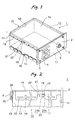
- a shield case 10 illustrated as an example is applied to a receiver 1 having a front plate 11 which is provided with a coaxial connector 3 for inputting high frequency signals and a feeder terminal connector 4 for outputting the high frequency signals as shown in Fig. 1.
- the receiver 1 includes circuit boards carrying thereon electronic elements and integrated circuit elements, etc. which constitute a receiving circuit, a control circuit, etc. or electronic components and so on contained in the shield case 10.
- the receiver 1 is constructed by fixing a front plate 11 of the shield case 10 to a C-shaped case consisting of a rear plate and side plates by caulking or the like.
- the shield case 10 is constructed in a box-like shape by assembling the front plate 11, left and right side plates 12, a rear plate 13, a top plate 14, and a bottom plate 15 which have been respectively formed of thin metal plates to one another. Because the left and right side plates 12 are equivalently formed members, only one of them will be described as a representative of the structure.
- the bottom plate 15 has a coupling structure with respect to the side plates 12 and the rear plate 13 which is equivalent to that of the top plate 14, and therefore, a detailed description of the bottom plate 15 will be omitted.
- the above described constituent members of the shield case 10 are not only formed independently, but an integral member consisting of the left and right side plates 12 and the bottom plate 15 formed in a substantially C-shape, or an integral member consisting of these plates and the rear plate 13 may be employed.
- the side plate 12 may be provided with an opening through which a pin connector mounted on a circuit board to perform a connection with a CPU is exposed outward, or the top plate 14 and the rear plate 15 may be formed with a plurality of undulated ribs for reinforcement.
- the side plate 12 is in a laterally elongated rectangular shape as a whole, and integrally provided with a plurality of caulking pieces at its front end edge and its back end edge respectively although not shown in the drawings. Each of the caulking pieces is constructed by bending a strip-like projection respectively projected from the front end edge and the back end edge inwardly substantially at the right angle.
- the side plates 12 are assembled to the front plate 11 and the rear plate 13 by caulking these caulking pieces into corresponding caulking holes to construct a rectangular framework as a whole. It is apparent that the front plate 11 and the rear plate 13 may be provided with the caulking pieces, while the side plates 12 may be provided with the caulking holes, or appropriate other coupling structures may be employed to assemble the shield case 10.
- the side plate 12 is provided with a pair of upper and lower stopper projections 16 on the outer face thereof.
- the stopper projections 16 are formed by stamping at the same time when a plate of metal material is subjected to a stamping process to form the side plate 12.
- the stopper projections 16 are formed along the upper and lower edges of the side plate 12 as laterally elongated rectangular projections in a longitudinal direction. It is apparent that a plurality of the stopper projections 16 may be formed in the upper and lower parts of the side plate 12.
- each of the stopper projections 16 may be formed in a wedge-like shape in cross section having a gradually increased projecting amount toward its upper edge portion or lower edge portion in a vertical direction.
- the top plate 104 has an outer profile which is larger than the framework constructed by assembling the aforesaid front plate 11, the rear plate 13 and the side plates 12.
- the top plate 104 is integrally provided with side face holding pieces 17 and a rear face holding piece 18 at both side edges and a back edge respectively.
- the side face holding pieces 17 and the rear face holding piece 18 or other parts of the top plate 104 which will be described below are formed at the same time when a plate of metal material is subjected to a stamping process.
- the side face holding pieces 17 are formed by bending inwardly substantially at the right angle, flange-like projections projected from both side edges of the top plate 14 along the substantially entire edges, and the side face holding pieces 17 are divided into a plurality of strip-like areas by forming a plurality of slits 19 which open at their lower end edges.
- the side face holding pieces 17 are rendered elastically deformable in a direction of their thickness.
- the side face holding pieces 17 are bent inwardly in a substantially V-shape to form holding projections 20.
- a distance between the opposed holding projections 20 of the left and right side face holding pieces 17 is narrower than a distance between the opposed left and right side plates 12.
- Each of the side face holding piece 17 is provided with a guide groove 21 in a vertical direction which opens at its lower end edge corresponding to the stopper projection 16 of the side plate 12.
- the guide groove 21 has an open width of a size enough to receive the stopper projection 16.
- An open edge 22 at the backward side is formed as a vertical wall and an open edge of the forward side consists of a slanted edge portion 23a which becomes larger toward the forward side and a vertical edge portion 23b which continues from the slanted edge portion 23a.
- the guide groove 21 is formed in the side face holding piece 17 in such a manner that a distance between a below mentioned rear face holding piece 18 and the vertical edge portion 23b of one of the open edges 23 is larger than a distance between a back end edge of the side plate 12 and a forward side edge of the stopper projection 16.
- An engagement groove 24 is formed in the guide groove 21 by horizontally cutting in the vertical edge portion 23b of the one open edge 23 in a forward direction.
- a width of the engagement groove 24 is larger than a width of the stopper projection 16, and a length of the engagement groove 24 is shorter than a length of the stopper projection 16.
- a vertical distance of the engagement groove 24 from a main face of the top plate 14 is substantially the same as a vertical distance of the stopper projection 16 from the upper edge of the side plate 12.
- the engagement groove 24 is formed in the one open edge 23 having a distance between its front end edge and the rear face holding piece 18 which is larger than the distance between the back end edge of the side plate 12 and the forward side edge of the stopper projection 16.
- the rear face holding piece 18 is also formed by bending inwardly substantially at the right angle, a flange-like projection projected from a back end edge of the top plate 14 along the substantially entire edge, and divided into a plurality of strip-like areas by forming a plurality of slits which open at the lower end edge, although not shown in the drawings.
- the rear face holding piece 18 is rendered elastically deformable in a direction of its thickness.
- the rear face holding piece 18 is bent inwardly in a substantially V-shape to form a holding projection 25.
- the rear face holding piece 18 is formed in such a manner that a distance between the holding projection 25 and a front end edge of the top plate 14 is smaller than a length of the side plate 12.
- the rear plate 13 is provided with click projections 26 on its outer face.
- the click projections 26 are formed by stamping at the same time when a plate of metal material is subjected to a stamping process to form the rear plate 13.
- the click projections 26 are in a semispherical shape as shown in Fig. 2, and a pair of the click projections 26 are formed along upper and lower edges of the rear plate 13 (the lower one is omitted in the drawings) respectively apart from each other in a direction of a width of the rear plate.
- a vertical distance of the click projection 26 from the upper edge of the rear plate 13 is smaller than a vertical distance of the holding projection 25 of the rear face holding piece 18 from the top plate 14. It is apparent that the structure of the click projection 26 need not be limited to such structure, but the click projection 26 may be formed in a wedge-like shape in cross section having a gradually increased projecting amount toward its upper edge part (or lower edge part) in a vertical direction.
- the top plate 14 which has been constructed as described above is assembled to the side plates 12 and the rear plate 13 which have been assembled beforehand, so as to cover them from above as shown by an arrow a in Fig. 4.
- the holding projection 25 of the rear face holding piece 18 is elastically deformed outward as shown by an arrow b in Fig. 4 and climbs over the click projection 26.
- the top plate 14 is prevented from being disengaged, since the holding projection 25 of the rear face holding piece 18 is brought in elastic contact with the outer face of the rear plate 13 and locked by the click projection 26.
- the entire top plate 14 moves forward through use of the slanted edge portion 23a and elastic force generated when the holding projection 25 of the rear face holding piece 18 climbs over the click projection 26. Thereby, the top plate 14 allows the stopper projection 16 to face with an opening of the guide groove 21 and to enter into the guide groove 21 along the slanted edge portion 23a.
- the stopper projection 16 As the top plate 14 is pushed in, the side edge of the stopper projection 16 is displaced from the slanted edge portion 23a to the vertical edge portion 23b along the one open edge 23 of the guide groove 21. After the holding projection 25 of the rear face holding piece 18 has climbed over the click projection 26, the stopper projection 16 is brought at a position facing with the engagement groove 24. When the elastic force of the rear face holding piece 18 is decreased in this state and the top plate 14 is displaced backward, the stopper projection 16 comes in engagement with the engagement groove 24 as shown in Fig. 2. Accordingly, the stopper projection 16 is displaced as shown by an arrow c in Fig. 4.
- the top plate 14 is assembled to the side plates 12 and the rear plate 13 by elastically abutting the holding projections 20 of the side face holding pieces 17 and the holding projection 25 of the rear face holding piece 18 against the outer faces of the side plates 12 and the rear plate 13 respectively. As described above, The top plate 14 is assembled to the side plates 12 and the rear plate 13 in a state where the holding projection 25 of the rear face holding piece 18 is locked by the click projection 26, and at the same time, the stopper projection 16 is engaged with the engagement groove 24.
- the bottom plate 15 is assembled to the side plates 12 and the rear plate 13 in a similar manner, because its coupling structure with respect to the side plates 12 and the rear plate 13 is constructed in the same manner as that of the top plate 14 as described above.
Landscapes
- Engineering & Computer Science (AREA)
- Microelectronics & Electronic Packaging (AREA)
- Shielding Devices Or Components To Electric Or Magnetic Fields (AREA)
- Casings For Electric Apparatus (AREA)
Abstract
Description
a guide groove for receiving the stopper projection and moving the top plate forward while the holding member climbs over the projection, and an engagement groove extending forward from an upper end of the guide groove, for engaging with the stopper projection in accordance with the rearward movement of the top plate when the holding member abuts on the outer face of the rear plate after climbing over the projection.
Claims (2)
- A shield case for housing an electronic equipment therein, comprising:a plurality of metal plates including a top plate, a bottom plate, a front plate, a rear plate, a pair of side plates, which are assembled to one another in a box-like shape;a projection, formed on an outer face of the rear plate;a stopper projection, formed on an outer face of each side plate;a rear face holding piece, downwardly extending from a rear edge of the top plate, the rear face holding piece formed with a holding member at a lower end portion thereof, the holding member elastically abutting on the outer face of the rear plate, after climbing over the projection; andside face holding pieces, downwardly extending from side edges of the top plate, each side face holding piece formed with a notched portion at a lower end portion thereof, the notched portion including:a guide groove for receiving the stopper projection and moving the top plate forward while the holding member climbs over the projection, andan engagement groove extending forward from an upper end of the guide groove, for engaging with the stopper projection in accordance with the rearward movement of the top plate when the holding member abuts on the outer face of the rear plate after climbing over the projection.
- The shield case as set forth in claim 1, wherein a width of the engagement groove is wider than a vertical width of the stopper projection, and a length of the engagement groove is shorter than a horizontal width of the stopper projection; and
wherein a distance between a front end of the engagement groove and the rear face holding piece is longer than a distance between a rear edge of the side plate and a front end of the stopper projection.
Applications Claiming Priority (2)
| Application Number | Priority Date | Filing Date | Title |
|---|---|---|---|
| JP2000096769 | 2000-03-31 | ||
| JP2000096769A JP4341140B2 (en) | 2000-03-31 | 2000-03-31 | Electronics |
Publications (3)
| Publication Number | Publication Date |
|---|---|
| EP1139711A2 true EP1139711A2 (en) | 2001-10-04 |
| EP1139711A3 EP1139711A3 (en) | 2003-09-10 |
| EP1139711B1 EP1139711B1 (en) | 2005-11-09 |
Family
ID=18611485
Family Applications (1)
| Application Number | Title | Priority Date | Filing Date |
|---|---|---|---|
| EP01108188A Expired - Lifetime EP1139711B1 (en) | 2000-03-31 | 2001-03-30 | Shield case for electronic equipment |
Country Status (4)
| Country | Link |
|---|---|
| US (1) | US6557957B2 (en) |
| EP (1) | EP1139711B1 (en) |
| JP (1) | JP4341140B2 (en) |
| DE (1) | DE60114688T2 (en) |
Cited By (3)
| Publication number | Priority date | Publication date | Assignee | Title |
|---|---|---|---|---|
| CN1297182C (en) * | 2003-03-27 | 2007-01-24 | 日本电气株式会社 | Housing of electronic apparatus |
| WO2015040011A1 (en) * | 2013-09-19 | 2015-03-26 | Aesculap Ag | Lockable pressure casing |
| US11002566B2 (en) | 2007-06-27 | 2021-05-11 | Brooks Automation, Inc. | Position feedback for self bearing motor |
Families Citing this family (19)
| Publication number | Priority date | Publication date | Assignee | Title |
|---|---|---|---|---|
| DE10260459A1 (en) | 2002-01-08 | 2003-08-14 | Mitsumi Electric Co Ltd | Shield sheathing for electronic devices |
| JP2007142166A (en) * | 2005-11-18 | 2007-06-07 | Pioneer Electronic Corp | Housing member, and electronic device |
| US8042890B2 (en) * | 2007-04-24 | 2011-10-25 | Edsal Manufacturing Co., Inc. | Boltless storage cabinet |
| US8283813B2 (en) | 2007-06-27 | 2012-10-09 | Brooks Automation, Inc. | Robot drive with magnetic spindle bearings |
| WO2009003187A1 (en) * | 2007-06-27 | 2008-12-31 | Brooks Automation, Inc. | Sensor for position and gap measurement |
| KR101660894B1 (en) | 2007-06-27 | 2016-10-10 | 브룩스 오토메이션 인코퍼레이티드 | Multiple dimension position sensor |
| US9752615B2 (en) | 2007-06-27 | 2017-09-05 | Brooks Automation, Inc. | Reduced-complexity self-bearing brushless DC motor |
| US8823294B2 (en) * | 2007-06-27 | 2014-09-02 | Brooks Automation, Inc. | Commutation of an electromagnetic propulsion and guidance system |
| CN101855811B (en) | 2007-06-27 | 2013-11-20 | 布鲁克斯自动化公司 | Motor stator with lift capability and reduced cogging characteristics |
| JP2011514652A (en) | 2007-07-17 | 2011-05-06 | ブルックス オートメーション インコーポレイテッド | Substrate processing apparatus with motor integrated in chamber wall |
| JP4857252B2 (en) * | 2007-12-07 | 2012-01-18 | 株式会社日立製作所 | Electronics |
| CN102245000A (en) * | 2010-05-11 | 2011-11-16 | 鸿富锦精密工业(深圳)有限公司 | Electronic device combination |
| KR101320521B1 (en) * | 2011-09-26 | 2013-10-22 | 도시바삼성스토리지테크놀러지코리아 주식회사 | Housing and disc drive adopting the housing |
| TW201316895A (en) * | 2011-10-14 | 2013-04-16 | Hon Hai Prec Ind Co Ltd | Printed circuit board capable of preventing electromagnetic interface |
| WO2014046098A1 (en) * | 2012-09-21 | 2014-03-27 | シャープ株式会社 | Mating structure for case |
| DE102012221778B4 (en) | 2012-11-28 | 2022-12-29 | Robert Bosch Gmbh | Battery with a housing part having a clamping extension and battery system and motor vehicle with battery |
| DE102014109821A1 (en) * | 2014-01-22 | 2015-07-23 | Hs Systemtechnik Gmbh | shield |
| DE102014109819B4 (en) * | 2014-01-22 | 2023-09-21 | iwis e-tec GmbH | shielding housing |
| DE102019200060A1 (en) * | 2019-01-04 | 2020-07-09 | Robert Bosch Gmbh | Housing element for a shielding device for receiving a control device for a vehicle system for a vehicle, shielding device with a housing element, method for producing a housing element and method for producing a shielding device |
Family Cites Families (8)
| Publication number | Priority date | Publication date | Assignee | Title |
|---|---|---|---|---|
| US4560079A (en) * | 1984-02-02 | 1985-12-24 | Burroughs Corporation | Equipment enclosure |
| US5398157A (en) * | 1993-04-13 | 1995-03-14 | Kingston Technology Corporation | Snap-in mounting bracket for a computer memory device |
| US5414597A (en) * | 1994-05-04 | 1995-05-09 | Ford Motor Company | Shielded circuit module |
| US5600538A (en) * | 1994-07-08 | 1997-02-04 | Apple Computer, Inc. | Personal computer and housing structure having circuit board removable horizontally and sub-chassis removable from the top thereof |
| JPH08139460A (en) * | 1994-11-11 | 1996-05-31 | Toshiba Corp | Electronic device structure |
| JP3179719B2 (en) * | 1996-11-20 | 2001-06-25 | アルプス電気株式会社 | Electronics |
| JPH11112181A (en) * | 1997-10-01 | 1999-04-23 | Nec Eng Ltd | Shield unit |
| DE29906726U1 (en) * | 1999-04-16 | 1999-07-01 | Mannesmann VDO AG, 60388 Frankfurt | Rectangular installation housing with the smallest dimension in the direction of the vertical axis |
-
2000
- 2000-03-31 JP JP2000096769A patent/JP4341140B2/en not_active Expired - Fee Related
-
2001
- 2001-03-27 US US09/817,400 patent/US6557957B2/en not_active Expired - Fee Related
- 2001-03-30 DE DE60114688T patent/DE60114688T2/en not_active Expired - Lifetime
- 2001-03-30 EP EP01108188A patent/EP1139711B1/en not_active Expired - Lifetime
Cited By (3)
| Publication number | Priority date | Publication date | Assignee | Title |
|---|---|---|---|---|
| CN1297182C (en) * | 2003-03-27 | 2007-01-24 | 日本电气株式会社 | Housing of electronic apparatus |
| US11002566B2 (en) | 2007-06-27 | 2021-05-11 | Brooks Automation, Inc. | Position feedback for self bearing motor |
| WO2015040011A1 (en) * | 2013-09-19 | 2015-03-26 | Aesculap Ag | Lockable pressure casing |
Also Published As
| Publication number | Publication date |
|---|---|
| EP1139711A3 (en) | 2003-09-10 |
| DE60114688D1 (en) | 2005-12-15 |
| US20010026116A1 (en) | 2001-10-04 |
| DE60114688T2 (en) | 2006-06-01 |
| EP1139711B1 (en) | 2005-11-09 |
| JP2001284876A (en) | 2001-10-12 |
| JP4341140B2 (en) | 2009-10-07 |
| US6557957B2 (en) | 2003-05-06 |
Similar Documents
| Publication | Publication Date | Title |
|---|---|---|
| EP1139711B1 (en) | Shield case for electronic equipment | |
| US6351394B1 (en) | Conductive frame for receiving an electronic module | |
| US6628524B1 (en) | Frame kit for IC card and IC card using the same | |
| US5525071A (en) | Low connection force electrical connector system | |
| US6655995B1 (en) | Electrical connector receptacle cage with interlocking upper and lower shells | |
| US6666720B1 (en) | Electrical connector receptacle with module kickout mechanism | |
| KR20190026011A (en) | connector | |
| EP1357640B1 (en) | Electric wire connecting connector | |
| KR200146618Y1 (en) | Electrical connector | |
| US20080174946A1 (en) | Computer enclosure with removable cover | |
| EP1326309A1 (en) | Shielded connector | |
| KR20220001094U (en) | Easy lock connector with unlock structure | |
| US7077696B2 (en) | Connector which can easily be mounted to an object and provided with EMI protection | |
| US7170013B2 (en) | Spring fingers with end extensions | |
| DE10260459A1 (en) | Shield sheathing for electronic devices | |
| US5137472A (en) | Means for securing ground plates to electrical connector housing | |
| US20100279546A1 (en) | Connector with two piece shells | |
| US4678256A (en) | Connector | |
| US7666031B2 (en) | Connector | |
| US20030129876A1 (en) | Latch for ground shield of an electrical connector | |
| US6582785B2 (en) | Shield case for electronic equipment | |
| KR102707012B1 (en) | Connector | |
| JPH11329598A (en) | Shield type connector assembly | |
| JP2757123B2 (en) | Mis-mating connector device | |
| JP2003241015A (en) | Optical connector with shielding mechanism |
Legal Events
| Date | Code | Title | Description |
|---|---|---|---|
| PUAI | Public reference made under article 153(3) epc to a published international application that has entered the european phase |
Free format text: ORIGINAL CODE: 0009012 |
|
| AK | Designated contracting states |
Kind code of ref document: A2 Designated state(s): AT BE CH CY DE DK ES FI FR GB GR IE IT LI LU MC NL PT SE TR |
|
| AX | Request for extension of the european patent |
Free format text: AL;LT;LV;MK;RO;SI |
|
| PUAL | Search report despatched |
Free format text: ORIGINAL CODE: 0009013 |
|
| AK | Designated contracting states |
Kind code of ref document: A3 Designated state(s): AT BE CH CY DE DK ES FI FR GB GR IE IT LI LU MC NL PT SE TR |
|
| AX | Request for extension of the european patent |
Extension state: AL LT LV MK RO SI |
|
| RIC1 | Information provided on ipc code assigned before grant |
Ipc: 7H 05K 9/00 A Ipc: 7H 05K 5/00 B |
|
| 17P | Request for examination filed |
Effective date: 20031125 |
|
| 17Q | First examination report despatched |
Effective date: 20040319 |
|
| AKX | Designation fees paid |
Designated state(s): DE |
|
| GRAP | Despatch of communication of intention to grant a patent |
Free format text: ORIGINAL CODE: EPIDOSNIGR1 |
|
| GRAS | Grant fee paid |
Free format text: ORIGINAL CODE: EPIDOSNIGR3 |
|
| GRAA | (expected) grant |
Free format text: ORIGINAL CODE: 0009210 |
|
| AK | Designated contracting states |
Kind code of ref document: B1 Designated state(s): DE |
|
| REF | Corresponds to: |
Ref document number: 60114688 Country of ref document: DE Date of ref document: 20051215 Kind code of ref document: P |
|
| PLBE | No opposition filed within time limit |
Free format text: ORIGINAL CODE: 0009261 |
|
| STAA | Information on the status of an ep patent application or granted ep patent |
Free format text: STATUS: NO OPPOSITION FILED WITHIN TIME LIMIT |
|
| 26N | No opposition filed |
Effective date: 20060810 |
|
| PGFP | Annual fee paid to national office [announced via postgrant information from national office to epo] |
Ref country code: DE Payment date: 20100430 Year of fee payment: 10 |
|
| PG25 | Lapsed in a contracting state [announced via postgrant information from national office to epo] |
Ref country code: DE Free format text: LAPSE BECAUSE OF NON-PAYMENT OF DUE FEES Effective date: 20111001 |
|
| REG | Reference to a national code |
Ref country code: DE Ref legal event code: R119 Ref document number: 60114688 Country of ref document: DE Effective date: 20111001 |