This invention relates in general to printing color images and in
particular to printing halftone color images in a wide variety of recipe colors.
Pre-press color proofing is a procedure used by the printing
industry to create representative images of printed material. This procedure
avoids the high cost and time required to produce printing plates and set-up a
high-speed, high-volume printing press to produce a single intended image for
proofing prior to a production run of the intended image. In the absence of prepress
proofing, a production run may require several corrections to the intended
image to satisfy customer requirements, and each of the intended images would
require a new set of printing plates. By utilizing pre-press color proofing, time
and money are saved.
A laser thermal printer having halftone color proofing capabilities
is disclosed in commonly assigned U.S. Patent No. 5,268,708 titled "Laser
Thermal Printer With An Automatic Material Supply," issued December 7, 1993
in the name of R. Jack Harshbarger, et al. The Harshbarger, et al. device is
capable of forming an image on a sheet of thermal print media by transferring dye
from dye donor material to thermal print media. This is achieved by applying
thermal energy to the dye donor material to form an image on the thermal print
media. The apparatus disclosed comprises a material supply assembly; a lathe bed
scanning subsystem, which includes a lathe bed scanning frame, a translation
drive, a translation stage member, and a laser printhead; a rotatable vacuum
imaging drum; and exit transports for the thermal print media and dye donor
material.
The Harshbarger, et al. apparatus meters a length of the thermal
print media in roll form from a material supply assembly. The thermal print
media is measured and cut into sheets of the required length, transported to the
vacuum imaging drum, and wrapped around and secured to the vacuum imaging
drum. Donor roll material is metered out of the material supply assembly,
measured, and cut into sheets of the required length. A sheet of dye donor
material is transported to and wrapped around the vacuum imaging drum, and
superposed in registration with the thermal print media. The scanning subsystem
traverses the printhead axially along the rotating vacuum imaging drum to produce
the image on the thermal print media. The image is written in a single swath,
traced out in a continuous spiral, concentric with the imaging drum, as the
printhead is moved parallel to the drum axis.
The Harshbarger et al. apparatus simulates the printing process by
imaging the dye donor material at a constant exposure. The dye donor is used to
mark or not mark the thermal print media similar to the printing process, which
either transfers or does not transfer ink. The apparatus allows the exposure to each
dye donor material to be varied over a limited range to allow the customer to
match the density of the of the dye deposited on the thermal print media with the
density of the ink which will be used to print the image on a press.
Although the printer disclosed in the Harshbarger, et al. performs
well, there is a long-felt need to be able to use colors other than the standard cyan,
magenta, yellow, and black (CMYK) in pre-press color proofing. The CMYK
colors are often referred to as process colors. In the printing industry additional
colors, other than cyan, magenta, and yellow, are used depending upon the graphic
designers intentions for the printed work. A "key" color may be added to
highlight a particular component of the artwork. For screened continuous tone
images this key color is typically chosen to be black. The image is modified to
use black to adjust the intensity level within the image instead of using cyan,
magenta, and yellow together. This is called under color removal. For some
work, the customer may choose to use another color, for example, brown, as the
key color. This may be appropriate, for example, on a cereal box or in an image
with a tan subject. To print the job the printer uses cyan, magenta, yellow and the
key color. To save money one or more of the colors may be eliminated. For
artwork the printing industry may print the job with the exact inks used by the
artist. In these cases the printer may be printing red, blue, or some combination of
colors which may or may not include CMYK.
In many cases the color of the subject may not be successfully
reproduced using the standard CMYK colorants. In this case an additional color
printing plate may be created to be printed with an ink which is a close match to
the desired color of the subject. This additional color is imaged with the CMYK
layers and is called a "bump" plate. It is important to note that one or more of the
process colors may be eliminated or replaced with the bump color. For instance if
a red color is used to bump the color of a red car, then the black or cyan process
color may be replaced with the red bump color.
In existing pre-press systems, additional donor colors would be
needed to accomplish this. For example, commercial systems such as Polaroid
Graphics Imaging Polaproof, Dupont Digital Halftone Proofing System, and
Imation Matchprint Laser Proof Technology, have all advertised the availability of
additional donor colorants to create digital halftone proofs with special colors.
This solution, however, requires the manufacturer to produce additional dye donor
sheet in special color, often in small volume. Small production runs like this, for
one color, are expensive.
Another problem arises when plates in the printing press are out of
register. In that case colors are imaged slightly wider and overlapped 440, as
shown in Figure 1, so that a white space error 450, shown in Figure 2, does not
occur. Figure 2 illustrates an error in alignment between the Kodak Yellow (PMS
123C) 410, and Kodak Red (PMS 485C) 402, color planes, which results in a
white space error 450 between the two colors. The printing industry hides this
defect by increasing the line width of a color such that errors in color placement
are hidden behind the darker color. For example, in Figure 1, the Kodak Yellow
410 is enlarged to expand behind Kodak Red 402, creating a darker outline 440.
This technique is called "trapping." It is important to be able to see the trapping
on each of the printed color planes in the halftone proof. The capability to show
trapping is not readily available in state of the art pre-press color proofers without
use of a special color dye donor sheet.
Printing presses traditionally uses a halftone screen to generate a
tone scale. The printing process is only capable of delivering or not delivering
ink, which is usually opaque. This is the binary printing process. To generate a
light tint, small dots of ink are used. To generate a darker tint the ink dots are
enlarged which touch and fill the space between dots. The halftone proofer
disclosed in US Patent number 5,268,708 images CMYK colorants at a high
resolution. For example, a Kodak Approval XP system produces images at either
2400 dpi or 2540 dpi using a software Raster Image Processor (RIP) to generate a
bitmap which determines when the lasers within the printer mark the CMYK
films. Figures 3, 4, and 5 demonstrate how a halftone image would look at
different magnifications. Tone scale is composed of colored dots which are
shown in the exploded views in Figures 4 and 5. The colors are arranged in a grid
and the pitch, dot to dot, is called the screen ruling in dots per inch. The angle of
the grid is called the screen angle. Each color is printed at a different screen angle
to hide the beating, or aliasing, caused by the alignment and accuracy of the color
screens to each other. For optimum conditions the cyan, magenta, and black
screens are each separated by 30 degrees. The fourth color, yellow, is then placed
at an angle halfway between the angle of two of the other colors. In Figures 4 and
5 yellow is between the cyan and magenta screens.
The color screens are separated out as planes 630, 640, 650, and
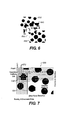
660 in Figure 6. Cyan plane 630, with a grid 670 superimposed over the halftone
dots 631 are comprised of micropixels 632 as shown in Figure 7. The software
RIP determines the positions in the grid when the laser needs to be energized to
print the halftone dot. While only cyan plane 630 is shown, a similar computation
is performed for the magenta plane 640, the yellow plane 650, and the black plane
660.
It is common practice in color proofing to represent special color
planes, i.e. planes containing colors other than the processes colors, by replacing
solid color areas with halftone patterns of the process colors as described for
example in US Patent No. 5,309,246. It is usually necessary to attach additional
instructions with these proofs to inform customers and printers that a substitution
has been made. It is highly desirable for halftone color proofing systems to
reproduce the special color planes with colors that more closely represent the final
print job. In the case of laser thermal material transfer proofing systems it is well
known that this can be accomplished by using individualized donors having the
unique color required for the special color plane, however, this process adds
additional expense as described above.
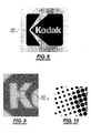
Figures 8, 9, and 10 demonstrates how the Kodak corporate logo
would look at different magnification using conventional halftone screens to
approximate Kodak Yellow and Kodak Red inks. Figures 9 and 10 are exploded
views of the halftone screening near the Kodak "K." Without special donor colors
to image Kodak Yellow and Kodak Red a digital halftone printer can only
approximate the finished image that will be printed on press. Also, as shown in
Figure 10, the trapping between colors cannot be clearly shown. A customer may
choose either to convert these special colors to process colors, CMYK, and use
halftone screens to approximate the color, or may choose to leave these features
off the proof. Neither of these solutions is acceptable.
It is the object of the present invention to provide a method and
apparatus for printing specialty color images having a color plane that is not a
standard CMYK process color. It is also an object of this invention to provide a
method and apparatus for printing a specialty color image using a special color
plane in addition to any combination of the CMYK process colors. It is also an
object of the present invention to provide a method and apparatus for showing
trapping using special colors. Yet another object is to print specialty colors using
a halftone color printer.
According to one aspect of the present invention an apparatus for
printing halftone recipe color images comprises a printhead which prints a first
color at a first intensity. A second color is printed at a second intensity and the
second color is superimposed and coextensive on top of the first color to produce a
recipe color, to create a specialty color on a digital pre-press proof. In one
embodiment a third color at a third intensity is superimposed on the first and
second color.
It is an advantage of the present invention that the interaction
between the recipe color and the other colors used in the job may be shown.
It is an advantage of the present invention that additional colors
besides the CMYK process colors, such as orange and green, may also be used in
the recipe color.
It is an advantage of the present invention that process colors may
be added to a pigmented donor to tint the pigmented color.
It is an advantage of the present invention that a recipe color may
be used to represent a process color. This allows changing the color of each
process color to an exact match of the ink which will be used to image the job on
press. The color match of a proofing system that matches the ink is superior to
other proofing systems.
It is an advantage of the present invention that the same donor used
for a process color plane may be used in a recipe color, saving the customer donor
sheets within a job.
It is an advantage of the present invention that any color within the
color space of the apparatus may be created by mixing the available colors
together in varying amounts. This alleviates the need for the customer to purchase
a special colored donor sheet for each color that she desires.
It is an advantage of the present invention that manufacturers do
not have to create, manufacture, store and sell discrete color rolls for each color
that the customer desires.
It is an advantage of the present invention that a unique color may
be generated to show the customer where the color will be in the printed job even
if the color is outside the color gamut of the donors which are in her machine.
This unique color will be visibly different from the process colors allowing the
customer to determine that the job will be printed properly.
It is an advantage of the present invention that the unique color
may be chosen to be the same hue or the same lightness as the desired color, even
if it is outside the color gamut of the donors within the machine.
It is an advantage of the present invention that a customer may
view a halftone proof with process colors plus the recipe colors which represents a
close approximation of the printed job without going to press, creating films, or
creating plates.
It is an advantage of the present invention that the trapping between
the colors in the job is easily identified.
It is an advantage of the present invention that the customer may
use a pigmented donor to be used as both a special color and as part of a recipe
color.
It is an advantage of the present invention that the customer may
proof only recipe colors instead of or in place of process colors. Jobs consisting of
only non-process colors may be proofed from recipe colors.
It is an advantage of the present invention that a stochastic screen
may be imaged using a recipe color made with this technique.
It is an advantage of the present invention that for a solid colorant
system, such as a pigmented system, pulse width modulation may be used to vary
the amount of colorant transferred within the micro-pixel dot to create a recipe
color mix.
The invention and its objects and advantages will become more
apparent in the detailed description of the preferred embodiment presented below.
The file of this patent contains at least one drawing executed in
color. Copies of the patent with color drawings will be provided by the Patent and
Trademark Office upon request and payment of the necessary fee. The colors in
the color drawings have been modified to highlight certain effects.
Figure 1 is a simulation of a graphic image consisting of two
special colors imaged using a high resolution imaging device, showing trapping.
Figure 2 is a simulation of a graphic image consisting of two
special colors imaged using a high resolution imaging device showing white space
error.
Figure 3 is a simulation of a halftone image.
Figure 4 is a simulation of an enlarged view of a portion of the
image shown in Figure 3.
Figure 5 is an enlarged view of a portion of the image shown in
Figure 4.
Figure 6 is an exploded view of the color planes which comprise
Figure 5.
Figure 7 is an enlarged view of the cyan color plane shown in
Figure 6.
Figure 8 is a simulated halftone image used to approximate
specialty colors.
Figure 9 is an enlarged view of a portion of Figure 8.
Figure 10 is an enlarged view of a portion of Figure 9.
Figure 11 is a side view, in vertical cross section, of an image
processing apparatus according to the present invention.
Figure 12 is a perspective view, partially in cross section, of a
vacuum imaging drum and a printhead according to the present invention.
Figure 13 is a schematic diagram of an apparatus for printing
halftone recipe color images according to the present invention.
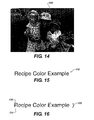
Figure 14 is a simulated halftone image using recipe colors.
Figure 15 is an enlarged portion of Figure 14 showing separation of
the color planes used to make recipe colors.
Figure 16 shows the two color passes required to create the recipe
color plane of Figure 15.
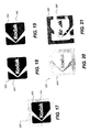
Figure 17 is a graphic color image using two special colors
according to the present invention.
Figure 18 shows the specialty color for red separated from the
graphic image in Figure 17.
Figure 19 shows the two color recipe used to form the specialty
color plane shown in Figure 18.
Figure 20 shows the specialty color yellow separated from the
graphic image shown in Figure 17.
Figure 21 shows the two color recipe used to form the recipe color
shown in Figure 20.
Figure 22 shows how the RIP generates the bitmap for the special
color plane shown in Figure 18.
Figure 23 is a graph of density versus exposure on a four color
digital halftone color proofer.
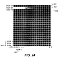
Figure 24 is a grid of recipe colors.
Figure 25 simulates a color halftone image.
Figure 26 simulates a color plane using a recipe color according to
the present invention.
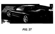
Figure 27 simulates the final image obtained by adding the recipe
color plane of Figure 26 to Figure 25.
The present description will be directed in particular to elements
forming part of, or cooperating more directly with, an apparatus in accordance
with the present invention. It is to be understood that elements not specifically
shown or described may take various forms well known to those skilled in the art.
While the invention is described below in the environment of a laser thermal
printer, it will be noted that the invention can be used with other types of imaging
apparatus.
Referring to Figures 11 and 12, there is illustrated an image
processing apparatus 10 according to the present invention having an image
processor housing 12 which provides a protective cover. A movable, hinged
image processor door 14 is attached to the front portion of the image processor
housing 12, which permits access to the two sheet material trays, lower sheet
material tray 50a and upper sheet material tray 50b, which are positioned in the
interior portion of the image processor housing 12 to support thermal print media
32. Only one of the sheet material trays will dispense the thermal print media to
create an intended image, the alternate sheet material tray either holds an
alternative type of thermal print media or functions as a back up sheet material
tray. In this regard, the lower sheet material tray 50a includes a lower media lift
cam 52a for lifting the lower sheet material tray 50a and ultimately the thermal
print media 32, upwardly toward a rotatable, lower media roller 54a and toward a
second rotatable, upper media roller 54b which, when both are rotated, permits the
thermal print media 32 to be pulled upwardly towards a media guide 56. The
upper sheet material tray 50b includes a upper media lift cam 52b for lifting the
upper sheet material tray 50b and the thermal print media 32 towards the upper
media roller 54b which directs it towards the media guide 56.
The movable media guide 56 directs the thermal print media 32
under a pair of media guide rollers 58 which engages the thermal print media 32 to
assist the upper media roller 54b in directing it onto the media staging tray 60.
The media guide 56 is attached and hinged to the lathe bed scanning frame 202 at
one end, and is uninhibited at its other end for permitting multiple positioning of
the media guide 56. The media guide 56 then rotates its uninhibited end
downwardly, as illustrated in the position shown, and the direction of rotation of
the upper media roller 54b is reversed for moving the thermal print medium
receiver sheet material 32 resting on the media staging tray 60 under the pair of
media guide rollers 58, upwardly through an entrance passageway 204 and around
a rotatable vacuum imaging drum 300.
A roll of dye donor roll material 34 is connected to the media
carousel 100 in a lower portion of the image processor housing 12. Four (or more)
rolls are used, but only one is shown for clarity. Each roll includes a dye donor
roll material of a different color, typically black, yellow, magenta and cyan. The
dye donor roll materials are cut into sheets and passed to the vacuum imaging
drum 300. A media drive mechanism 110 is attached to each roll of dye donor roll
material 34, and includes three media drive rollers 112 through which the dye
donor roll material 34 is metered upwardly into a media knife assembly 120.
After the dye donor roll material 34 reaches a predetermined position, the media
drive rollers 112 cease driving the dye donor roll material 34 and the two media
knife blades 122 positioned at the bottom portion of the media knife assembly 120
cut the dye donor roll material 34 into sheets. The lower media roller 54a and the
upper media roller 54b along with the media guide 56 then pass the dye donor
sheet 36 onto the media staging tray 60 and to the vacuum imaging drum 300 and
in registration with the thermal print media 32 using the same process as described
above for passing the thermal print media 32 onto the vacuum imaging drum 300.
The dye donor sheet 36 rests atop the thermal print media 32 with a narrow gap
between the two created by microbeads imbedded in the surface of the thermal
print media 32.
A laser assembly 400 includes a quantity of laser diodes 403 in its
interior, the laser diodes 403 are connected via fiber optic cables 404 to a
distribution block 406 and ultimately to the printhead 500. The printhead 500
directs thermal energy received from the laser diodes 403 causing the dye donor
sheet to pass the desired color across a gap to the thermal print media 32. The
printhead 500 moves axially along the longitudinal axis of the vacuum imaging
drum 300 for transferring the data to create the intended image onto the thermal
print media 32.
For writing, the vacuum imaging drum 300 rotates at a constant
velocity, and the printhead 500 begins at one end of the thermal print media 32
and traverse the entire length of the thermal print media 32 for completing the
transfer process for the particular dye donor sheet resting on the thermal print
media 32. After the printhead 500 has completed the transfer process, for the
particular dye donor sheet, the dye donor sheet is removed from the vacuum
imaging drum 300 and transferred out the image processor housing 12 via a skive
or ejection chute 16. The dye donor sheet 36 eventually comes to rest in a waste
bin 18 for removal by the user. The process described above is then repeated for
the other rolls of dye donor material.
After the color from all four sheets of the dye donor sheets 36 have
been transferred and the dye donor sheets 36 have been removed from the vacuum
imaging drum 300, the thermal print media 32 is removed from the vacuum
imaging drum 300 and transported via a transport mechanism 80 to a color
binding assembly 180. The media entrance door 182 of the color binding
assembly 180 is opened permitting the thermal print media 32 to enter the color
binding assembly 180, and shuts once the thermal print media 32 comes to rest in
the color binding assembly 180. The color binding assembly 180 processes the
thermal print media 32 for further binding the transferred colors on the thermal
print media 32 and for sealing the microbeads thereon. After the color binding
process has been completed, the media exit door 184 is opened and the thermal
print media 32 with the intended image thereon passes out of the color binding
assembly 180 and the image processor housing 12 and comes to rest against a
media stop 20.
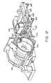
Referring to Figure 12, vacuum imaging drum 300 is mounted for
rotation about an axis 612 in a drum frame member 614. The imaging drum is
adapted to support a thermal print media while dye is transferred from the donor
sheet to a receiver sheet as a result of heating the dye in the donor sheet. The
donor sheet and the receiver sheet are superposed in intimate contact and are held
onto the peripheral surface of the drum by vacuum applied to the superposed
elements from the interior of the drum. The donor sheet, when irradiated, converts
light energy to heat energy. The dye in the immediate vicinity is heated to its
vaporization temperature for transfer to the receiver sheet.
A movable writing head assembly 616 is movably supported
adjacent vacuum imaging drum 300, and includes a printhead 500 which is
mounted on a translator member 620 which, in turn, is slidably supported on bars
622 and 624, which are parallel to the axis 612 of vacuum imaging drum 300.
Translator member 620 is driven by a motor, not shown, which rotates a lead
screw 626 parallel to bars 622 and 624 to move printhead 500 parallel to the axis
of the drum.
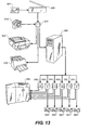
A schematic of the workflow for this invention is shown in Figure
13. A customer image 501 is captured as a positive film, negative film, or print.
The image is then scanned on a scanner 505 and saved as a digital file 510. The
file will have an associated color space such as Red, Green, Blue (RGB), CMYK,
or Luminance and Chrominance (L*a*b*), which defines the colors used in each
color plane for each pixel. Each pixel in the digital file will also have a bit depth
for each color plane such as 8 bits or 12 bits which determines how many unique
levels are possible for each pixel. A digital camera 515 may also be used to
directly create the digital file 510.
Once the customer has the digital file she may manipulate it using
special software. The customer may perform operations such as adding text,
cropping, rotating, resizing, changing the color, change the contrast, etc. The
customer may also import the image into an illustration program. Using special
software the customer may create a logo with portions of real pictures used to
texture a surface. The customer may also use page layout software to compose
pages containing text, images, and artwork. These operations may be performed
with commercially available software. The result is a composite page stored as a
digital file 510.
To view this composite file the customer may print it to a thermal
printer 520. Software on the printer, or alternatively in a computer, converts the
scanned images, artwork, and text to drive the thermal printer. Thermal printers
are available with 300 to 600 dpi output resolutions. Commercially available
thermal printer uses cyan, magenta, and yellow donors with multiple levels of
colorant per pixel. Because the thermal printer allows multiple levels of each
color per pixel it is considered a continuous tone device.
The customer may also use a color ink jet printer 530 to view the
composite page. Ink jet printers are available with writing resolutions between
300 and 1440 dpi. These printers use multiple dots, multiple dot sizes, dithered or
stochastic screens, and multiple ink colors to simulate continuous tone images.
Software in a computer or within the printer is used to render the composite page
on the ink jet printer. Ink jet printers typically use multiple levels of cyan,
multiple levels of magenta, one level of yellow, and one level of black ink to
cover the tone range of most images. Ink jet printers may also include orange and
green inks, in addition to CMYK, to reproduce high fidelity color. Because the
ink jet printer may deposit or not deposit ink it is considered a binary device. An
ink jet printer with multiple levels of a single colorant, such as two levels of cyan
ink, would be considered a multiple level binary device.
To prepare a halftone color proof using recipe colors according to
the present invention, the customer prints a proof on a color digital proofer 550,
the operation of which has been described in detail above with respect to Figures
11 and 12, to view the composite page. A software RIP running on a personal
computer 540 converts the composite page into cyan 544, magenta, 543, yellow
542, and black 541 bitmap files. Bitmap files contain one bit for each pixel. This
type of software is available commercially. A typical printer writes at 1800 dpi,
although printers which image at either 2400 or 2540 dpi are also available. The
RIP outputs the bitmap files at the resolution of the writing device. The RIP
converts the images in the digital file 510 to a halftone screen with a screen ruling
and screen angle chosen by the customer. The RIP then combines the halftoned
images with the artwork, line work, and text into the digital file 510 to create the
bitmap files for cyan 544, magenta 543, yellow 542, and black 541. The bitmap
files are used by the color digital proofer 550 to image the cyan, magenta, yellow,
and black donors.
Art work may consist of scanned images of hand drawings using
solid color inks, crayons, and paint; digital images which are created using
illustration software; or continuous tone images created using photo editing
software. Continuous tone images must be screened using the RIP. Digital files
containing line work and text define graphics which are composed of solid colors.
These colors are usually special colors which can not be reproduced by using the
process colors at their full intensity. For each special color the RIP 540 will create
a special color bitmap 545 unless the customer chooses the option to convert the
special colors into process colors. To convert to process colors the RIP 540
screens the special color and includes in the process color bitmaps, 541, 542, 543,
and 544. If the customer chooses not to convert the process colors, and the special
colored donor is not available then the special color will be omitted from the proof
leaving a white space on the proof where the special color would normally be
printed.
In a printing press the bitmap would be used to create printing
plates. Each color requires its own plate. The black color bitmap file 541 is used
to create the black color plate 560. The cyan 544, magenta 543, and yellow 542
bitmap files are used to create the cyan 563, magenta 562, and yellow 561 printing
plates. If a special color is to be printed then the special color bitmap 545 is
required to create the special color printing plate 563. If multiple special colors
are to be printed then multiple special color bitmaps and plates are required.
In a printing press the press may deposit ink, or not deposit ink.
This is a binary process. The digital halftone proofer 550 simulates this binary
process by marking the dye donor film 36 to transfer dye to the thermal print
media 32 in a binary manner at the writing resolution of the digital halftone
proofer 550. Each writing pass is written using a constant exposure to create a
density level of the dye on the thermal print media which is substantially the same
as the density level of the ink which will be transferred by the printing press.
If a special color dye donor is available then a bitmap to image that
special color dye donor 545 may be used to image the color in the digital halftone
proofer 550. If the special color dye is not available, the present invention creates
a recipe color from the dye donor colors which are in the machine. The RIP 540
creates the special color bitmap file and saves it as a recipe color bitmap file 546.
The digital halftone proofer 550 utilizes the process colors and special colors
contained within the media carousel 100. A subset of the media loaded into the
machine is imaged using the recipe color bitmap 546. Each dye donor used in the
recipe is imaged with the same recipe color bitmap.
In addition to imaging the dye donors 36 contained within the
carousel 100, the exposures used to image each dye donor is varied to transfer the
desired amount of each colorant. This results in a recipe color plane composed of
one or more colorants deposited on the thermal print media 32. By adjusting the
exposures for each color used in the recipe, a large number of colors in the color
gamut of the dye donors loaded into the machine are obtained, which are different
from any of the original dye donor colors.
Referring now to Figures 14 and 15, a halftone color image is
shown using a recipe color in an additional color plane 680. A magenta pass 690,
and a yellow pass 700, shown in Figure 16, are used to create the red recipe color
shown in plane 680. To produce the recipe color, the RIP generates one additional
bitmap plane for each recipe color. This is shown as the recipe color bitmap 546
in Figure 13. The same bitmap is used to image magenta pass 690 and yellow
pass 700. It is obvious to those skilled in the art to show that a recipe color could
be composed with one color. For instance a light or dark magenta. The more
common practice, however, would be to compose a recipe with two or more
colors. For instance a light gray recipe color may be composed using cyan,
magenta, and yellow exposures. Alternatively, a light gray color may be
composed using cyan, magenta, yellow, and black.
While the example shows that red text has been added to the image
shown in Figure 14, the same techniques can be used to add a screened red image,
or other recipe color, to the process image. This would be the case for imaging a
bump plate on top of a process color image to highlight the bump color. Although
the example uses process colors in combination with one recipe color, multiple
recipe colors may be added to a single image or combination of images. Also, the
example uses process colors, however, the customer image may consist of only
multiple recipe colors, or one recipe color, or a combination of recipe colors with
process colors.
An image, which has been stored as a digital file, is in a continuous
tone format, and may be transformed into different colorants other than CMYK,
using specialized software. For example, Photospot CT for Photoshop allows the
user to create a spot color plane from a three color image. Powertone by Intense
Software for Photoshop allows the user to convert a three color image into a
duotone image. The printer will then use these other colorants to reproduce the
job. To create proofs of these jobs prior to imaging on a high-speed, high volume
press currently requires the customer to create films for each color layer and use
an analog proofing process such as Dupont Matchprint. If the customer chooses
her ink colors to be one of the few donors available in a digital halftone proofing
system, she may proof the job using those specialty donors. The Dupont Digital
Halftone Proofing System suggests using the digital proof with the process colors,
and overlaying an analog proof of the specialty color using Dupont's Waterproof
Color Versatility System.
Figures 17-21 further illustrate the present invention. In Figure 17,
two recipe colors are used to image the Kodak Corporate Logo 302. The two
recipe colors are Kodak Red 402, and Kodak Yellow 410. The Kodak Red is
shown as Recipe color plane 320, in Figure 18, which is composed of a magenta
pass 330 and a light yellow pass 340, shown in Figure 19. The Kodak Yellow
shown as a Recipe color plane 370 in Figure 20, composed of a light magenta pass
380 and a medium yellow pass 390, shown in Figure 21.
For each of the recipe colors the software RIP, produces a bitmap
which is used to drive the lasers for the colors in the Recipe Color. For the
example in Figures 17-21, the recipe color bitmap stored as 546 in Figure 13
might contain the bitmap for the Kodak Red. Another recipe color bitmap, not
shown, is used to store the recipe color bitmap for Kodak Yellow. Figure 22
shows the grid 360 that the RIP uses to create the bitmap for the Kodak Red recipe
color plane 320. The same bitmap is used to image the magenta pass 330 and
light yellow pass 340, superimposing both colors on top of each other. The RIP
generates another bitmap for the Kodak Yellow Recipe color plane 370, which
will be used to image both the light magenta 380 and the medium yellow 390
color passes.
While all of these examples show the use of recipe colors to image
a solid graphic special color, one skilled in the art will recognize that the cyan
bitmap 544 of Figure 13, consisting of the micropixels 632 in Figure 7 which
compose the cyan halftone screen 631, may also be imaged as a recipe color.
Similarly the magenta 543, yellow 542, and black 541 bitmaps may also be
imaged as unique recipe colors.
The sensitometric curves of Kodak Approval donors are shown in
Figure 23. Figure 23 shows the exposures required to obtain a 1.17 cyan, 1.25
magenta, 0.87 yellow, and 1.67 black. These exposures may be typical of the
exposures required to image the cyan, magenta, yellow, and black layers at a
density level which would be similar to the cyan, magenta, yellow, and black ink
density level used on a four color press. Figure 23 shows that there are other
exposures that may be utilized to obtain differing amounts of density from the
same cyan, magenta, yellow, and black donors. The present invention changes the
exposure of the printer by varying the laser power and or the writing speed of the
printer to achieve a density other than the normal density used. This allows
mixing differing amounts of color in the same micropixel to achieve another
unique color composed of one or more of the original colors.
Another method of changing the exposure is to modulate the laser
writing system on a micropixel basis. This is a form of pulse width modulation,
which has the same effect as changing laser power or drum speed. The advantage
of this type of modulation is apparent when imaging binary colorant donors such
as the donors manufactured by Imation and Polaroid. Recipe colors may be
created by pulse width modulating the micropixel dot to mix a solid colorant with
the paper on a subhalftone dot scale.
A Kodak Approval XP4 printer was used to image a proof at the
Specification for Web Offset Printing (SWOP) conditions with cyan status T
density at approximately 1.30 density absolute on Textweb paper. Imaging cyan
at a different exposure to obtain a cyan color of 1.0 density would result in a
screened image representing another cyan ink that could be used in the printing
process. Figure 24 shows that the required exposure to obtain a 1.0 cyan density
is about 155 mJ/cm2 and is well within the capability of the cyan donor. This
would be a case where the recipe color is composed of a single colorant.
For some instances of recipe colors, such as text, the underlying
image is not printed. In this case there would be no process color under the recipe
color. This means that no cyan, magenta, yellow, or black colorant has been used
from the original color donors. In these cases the exposure may be changed, and
the recipe color component imaged utilizing the same donor sheet used to image
the process color plane.
For some applications, such as text, or large solid areas of color,
the process colors and recipe colors overlap. This is performed so that if the plates
on the printing press are slightly out of alignment a white space error is not
created. The Kodak Approval halftone color proofer utilizes approximately 30%
of the colorant in the dye donors to image a process color. This leaves sufficient
colorant in the dye donor to be used for an additional recipe color pass using the
same dye donor sheet. When the recipe color overlaps a process color there will
be a significant change in color which allows the customer to clearly judge the
trapping in the halftone proof.
In the present invention, millions of recipe colors are available to
choose from. Plus there are multiple combinations of process colors which will
result in visually similar colors. To select a recipe color, the color proofer may be
programmed to create a regularly varying grid of recipe colors shown in Figure
24. This is done by programming the printer to vary the exposure of a first color
800 in the x direction 801. Then the second color 802 is imaged, and
superimposed on the first color, by varying the exposure in the y direction 803.
The apparatus allows the operator to add a fixed amount of third color 804 on top
of the first and second colors 800 and 802. This results, for example, in a twenty
by twenty-one grid of color patches where column T is solid second color 802.
Row 20 is solid first color 800. Row 21 is solid third color 804. Row 1 Column
A through Row 19 Column S are varying amounts of first and second colors with
a fixed amount of third color. The customer may select one of these color patches
or run additional test images to select her desired recipe color. The customer
enters the recipe grid page; the x, y coordinates; or the patch number, to instruct
the machine which exposures to use to produce the customer's special color.
Additional solid colors may be added on top of the row 1 column A through row
19 column S to create the recipe color. The third color in row 21 may be omitted
to create a recipe with only colors 800 and 802.
In addition to imaging the recipe test page, solid patches of each
color for each exposure are also created. Solid patches of first color 800 compose
row 20. Solid patches of second color 802 compose column T. Solid patches of
third color 804 compose row 21. This allows the recipe color to be modeled as a
function of the individual colorants. Each recipe test patch is linearly interpolated
to estimate the required exposure to obtain a given color with reasonable results.
This data base is then used to guide customer's exposure selections to obtain a
desired color. The L*,a*,b* color space is used to specify the desired recipe color.
This color space is familiar to those skilled in the art and recognized by our
customers.
Figures 25-27 show an example of a recipe color, or specialty
color, used to simulate a bump plate in printing. In Figure 25 a car has been
imaged however, the color of the car does not match the actual color of the
subject. A bump plate shown in Figure 26 is prepared as a separate color plane
according to the present invention and imaged over the halftone image in Figure
25 to create the finished product shown in Figure 27.
One skilled in the art will recognize that the number of patches in
the recipe test image is not significant. One skilled in the art will also recognize
that this same test image may be used with cyan, magenta, yellow, black, silver,
orange, green, pink, light cyan, or any other available colorant. One skilled in the
art will recognize that colorants from the same family of products do not need to
be used. For example, pigmented donor may be used with other pigmented
donors, or in combination with dye donor.
One skilled in the art will recognize that a recipe color page
consisting of three or more colors maybe created. For instance four images
consisting of four rows by four columns maybe created where colors, 1, 2, and 3
have four levels each.
While our example uses process colors in combination with one
recipe color, multiple recipe colors may be added to a single image or combination
of images. While our example uses process colors, the customer image may
consist of multiple recipe colors, or just one recipe color, or a combination of
recipe colors with process colors. Although the invention has been described
using CMYK to create recipe colors, special donors such as green, pink, orange,
light cyan, or silver may be used to create a distinct recipe color. Those skilled in
the art will recognize that other colors that may be desirable to form the basis for a
recipe color. Although the term dye donor has been used throughout the
specification, the invention is intended to cover pigmented donor sheets, colored
wax donor sheets, and other color transfer means.