EP1139628A2 - Multicarrier receiver with channel estimation, for multiple access channels - Google Patents
Multicarrier receiver with channel estimation, for multiple access channels Download PDFInfo
- Publication number
- EP1139628A2 EP1139628A2 EP01302593A EP01302593A EP1139628A2 EP 1139628 A2 EP1139628 A2 EP 1139628A2 EP 01302593 A EP01302593 A EP 01302593A EP 01302593 A EP01302593 A EP 01302593A EP 1139628 A2 EP1139628 A2 EP 1139628A2
- Authority
- EP
- European Patent Office
- Prior art keywords
- receiver
- channel
- matrix
- delay function
- developing
- Prior art date
- Legal status (The legal status is an assumption and is not a legal conclusion. Google has not performed a legal analysis and makes no representation as to the accuracy of the status listed.)
- Withdrawn
Links
Images


Classifications
-
- H—ELECTRICITY
- H04—ELECTRIC COMMUNICATION TECHNIQUE
- H04L—TRANSMISSION OF DIGITAL INFORMATION, e.g. TELEGRAPHIC COMMUNICATION
- H04L27/00—Modulated-carrier systems
- H04L27/26—Systems using multi-frequency codes
- H04L27/2601—Multicarrier modulation systems
- H04L27/2647—Arrangements specific to the receiver only
-
- H—ELECTRICITY
- H04—ELECTRIC COMMUNICATION TECHNIQUE
- H04L—TRANSMISSION OF DIGITAL INFORMATION, e.g. TELEGRAPHIC COMMUNICATION
- H04L25/00—Baseband systems
- H04L25/02—Details ; arrangements for supplying electrical power along data transmission lines
- H04L25/0202—Channel estimation
- H04L25/0204—Channel estimation of multiple channels
-
- H—ELECTRICITY
- H04—ELECTRIC COMMUNICATION TECHNIQUE
- H04L—TRANSMISSION OF DIGITAL INFORMATION, e.g. TELEGRAPHIC COMMUNICATION
- H04L25/00—Baseband systems
- H04L25/02—Details ; arrangements for supplying electrical power along data transmission lines
- H04L25/0202—Channel estimation
- H04L25/024—Channel estimation channel estimation algorithms
- H04L25/0242—Channel estimation channel estimation algorithms using matrix methods
-
- H—ELECTRICITY
- H04—ELECTRIC COMMUNICATION TECHNIQUE
- H04L—TRANSMISSION OF DIGITAL INFORMATION, e.g. TELEGRAPHIC COMMUNICATION
- H04L5/00—Arrangements affording multiple use of the transmission path
- H04L5/02—Channels characterised by the type of signal
- H04L5/023—Multiplexing of multicarrier modulation signals, e.g. multi-user orthogonal frequency division multiple access [OFDMA]
Definitions
- This invention relates to channel estimation, and more particularly for channel estimation in clustered OFDM receivers.
- Orthogonal frequency division multiplexing has been shown to be an effective technique for combating multipath fading and is, therefore, a promising technique for wideband wireless packet data.
- clustered OFDM has been proposed to provide in-band diversity gain with wideband dispersive fading channels and to thus improve system performance.
- each user accesses several OFDM clusters located at different frequencies. This is illustrated in FIG. 1, where a wideband OFDM signal is divided into many non-overlapped clusters of tones in frequency, and each user accesses several clusters of tones. For example, in the FIG. 1 arrangement User 1 utilizes the first, fifth, ninth, and thirteenth clusters; and Users 2, 3, and 4 use other clusters.
- an error correction code such as a Reed-Solomon code or a convolutional code is used to create frequency diversity.
- differential demodulation has to be used instead of coherent demodulation, suffering a 3-4 dB loss in signal-to-noise ratio (SNR) performance.
- SNR signal-to-noise ratio
- pilot-symbol-aided or decision-directed channel estimators are used to obtain information.
- Similar parameter estimators are used to estimate the coefficients for the minimum-mean-square error diversity combiner (MMSE-DC) for OFDM systems with antenna arrays to suppress co-channel interference, or to estimate channel information required by the decoder of space-time code based transmitter diversity.
- MMSE-DC minimum-mean-square error diversity combiner
- the optimum transform for channel estimation is the eigen matrix of the channel frequency-domain correlation matrix.
- the optimum transforms depend on the channel delay profiles that vary with environments. Since there may be over a hundred contiguous tones for classical OFDM systems, the discrete Fourier transform (DFT) can be used instead of the optimum transforms, with negligible edge effects.
- DFT discrete Fourier transform
- each cluster contains many fewer tones than in classical OFDM, and those tones that are on the edge of a cluster constitute a large portion of the total number of tones in each cluster. Consequently, edge effects are unsatisfactorily large if a DFT is used for the estimator in clustered OFDM.
- An OFDM receiver is realized by applying incoming signals that arrive at one or more antennas, over respective transmission channels, to respective FFT (Fast Fourier Transform) elements, filtering the outputs of the FFT elements, combining the filtered signals, and applying the combined signal to a threshold element.
- the filter parameters are developed from channel estimates based on the signals developed by the FFT elements and the output of the threshold element, exploiting the channels' frequency correction both in time and frequency domain.
- the optimum channels estimator requires use of the eigen matrix of the channel's frequency-domain correlation matrix, which depends on the channels' delay profiles. In accordance with the principles disclosed herein, a simpler realization is obtained by employing a simple estimate of the delay profile, such a rectangular profile, or exponential delay profile.
- An OFDM signal is constructed in a transmitter by taking blocks of symbols and applying the blocks to an inverse FFT process. The signal is then transmitted, where it passes through a wireless channel before the receiver's antennas receive it.
- the complex baseband representation of a wireless channel impulse response can be described by where ⁇ k is the delay of the k th path, and ⁇ k ( t ) is the corresponding complex amplitude.
- ⁇ k is the delay of the k th path
- ⁇ k ( t ) is the corresponding complex amplitude.
- the ⁇ k ( t )' s can be viewed to be wide-sense stationary (WSS), narrow-band, complex Gaussian processes with average power ⁇ 2 / k ' s , where the different ⁇ ' s are independent of each other.
- FIG. 2 A block diagram of a receiver in accordance with the principles disclosed herein is shown in FIG. 2. As depicted, it contains two receiving antennas, but it should be understood that the arrangement could have one antenna or many antennas. An OFDM signal generated elsewhere by a transmitter is received at antenna 11 and is applied to FFT 12.
- the output signal of FFT 12 y[1, n , k ] corresponds to a n , k H [1, n , k ] + W 1, n , k , where a n , k is the signal encoded in the transmitter with an inverse FFT process at time n, with OFDM tone k , H [1, n, k ] corresponds to the transfer function of the channel between the transmitting antenna and receiving antenna 11, and W 1, n , k is the noise received at antenna 11.
- the output signal of FFT 12 is applied to filter 13, which develops the signal y [1, n , k ] H *[1, n , k ], where H and [1, n, k ] is an estimate of the channel H [1, n , k ], obtained from estimation augmentation (AU) block 33.
- an OFDM signal is received at antenna 21 and is applied to FFT 22.
- the output signal of FFT 22, y [2, n , k ], is applied to filter 23, which is responsive to signal H and [2, n , k ] from AU block 33.
- the output signals of filters 13 and 23 are combined in element 30 and applied to decision block 31.
- the output signal of decision block 31 is the decoded output signal, a [ n , k ], and that signal is applied to estimator block 32.
- This signal is applied to AU block 33, where augmented channel estimates H [ i , n , k ] are developed, as disclosed below.
- estimator 32 With respect to each antenna i , estimator 32 develops a set of estimates that can be expressed in terms of a vector AU element 33 processes the elements of each such vector (i.e., separately for each receiving antenna) as shown in FIG. 3. It exploits the above-described channel's frequency correlations in both time and frequency domain.
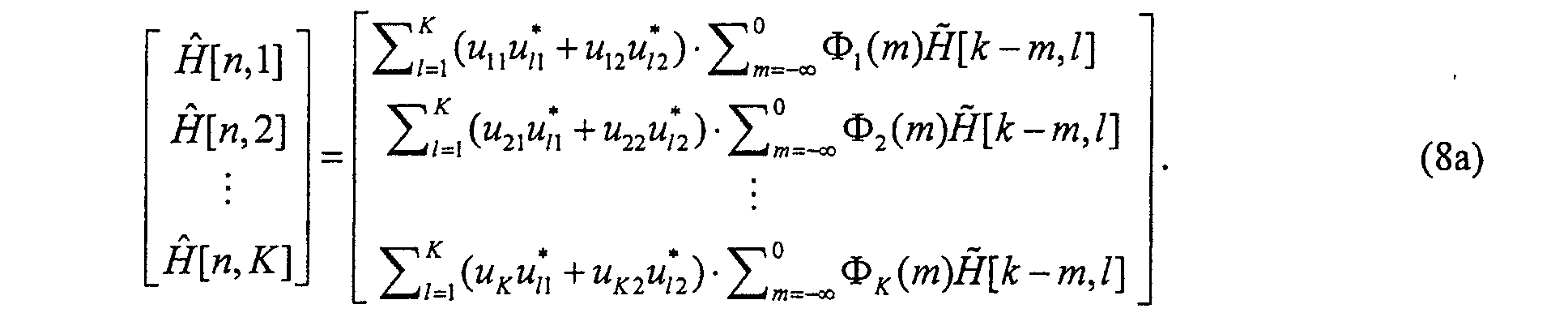
- FIG. 3 depicts a processing that is performed on the signal developed by estimator block 32, computing a subset of the matrix product U H in element 41, multiplying the subset results by ⁇ ( k ) in elements 42 and 43, and then multiplying the result by the transform U in element 44 (where the is the [ n , k ] of equation (7), and U H is the Hermetian of U H ).
- FIG. 3 shows only two filters ⁇ ( k ) being employed, to illustrate the fact that some delay paths are weak enough that a computation, should it be carried out, would carry a relatively large noise component and a small signal component. In such circumstances, there is an insufficient benefit to bother with the computational burden and, accordingly, less that a full set of K filters can be employed ( K /4 will typically suffice).
- K /4 will typically suffice.
- R f the channel's frequency-domain correlation matrix
- D the optimum transforms or bases for estimators are very difficult to obtain; particularly in a changing environment that is sometimes associated with cellular telephony (e.g., when the cell phone is used in a car).
- the unitary transform can be substituted by the DFT; that is,
- the tones that are on edge are a large portion of the tones per cluster. Therefore, as indicated above, the edge effects would cause a significant performance degradation if the DFT is used in the estimator.
- the simplest delay profile that provides good results is a rectangular profile, which can be expressed as where ⁇ max is half of the maximum delay span.
- the frequency-domain correlation function can be obtained by Based on r rec ( ⁇ f ), the optimum transform for the rectangular profile, U rec , can be obtained by the means of eigen-decomposition, which is a well known technique.
- equation (13) the various elements in the R f matrix are computed, and once the matrix is known, employing the eigen-decomposition technique provides the matrix U rec .
- each delay profile is specified by the average power of each path and delay, an ellipse can represent the average power in the different directions.
- the average power on each direction for delay profile I can be shown by the solid ellipse with eignvectors v 1 , v 2 .
- the channel parameters can be represented by ⁇ 1 v 1 + ⁇ 2 v 2 , where ⁇ 1 and ⁇ 2 are time varying for a time-varying channel.
Landscapes
- Engineering & Computer Science (AREA)
- Signal Processing (AREA)
- Computer Networks & Wireless Communication (AREA)
- Power Engineering (AREA)
- Physics & Mathematics (AREA)
- Mathematical Physics (AREA)
- Radio Transmission System (AREA)
- Cable Transmission Systems, Equalization Of Radio And Reduction Of Echo (AREA)
- Noise Elimination (AREA)
- Mobile Radio Communication Systems (AREA)
Abstract
Description















Claims (7)
- A receiver comprising:one or more FFT elements responsive to respective receiving antennas, each developing a signal y[i,n,k], over channel i, where i designates an FFT element, n designates time, and k designates tone;a corresponding set of one or more filters, each responsive to a corresponding output signal of an FFT element for developing a signal y[i,n,k]H and*[i,n,k] ;a combiner responsive output signals of said one or more filters;a threshold decision element responsive to output signal of said combiner; anda channels estimator, responsive to output signal of said threshold decision element and to signals y[i,n,k] of all of said one or more FFT elements, for developing said signals H and*[i,n,k], said channel estimator including a multiplication element for developing signalsand a matrix multiplication element for developing signals
 where umn where are element of a matrix U is related to a Discrete Fourier Transform of a delay function, Φi (k) = 1 - 1 / ml (-k)γ l [0], Mi (k) is a stable one-sided Fourier transform
 , and γ i [n] is a coefficient in the frequency response of channel i.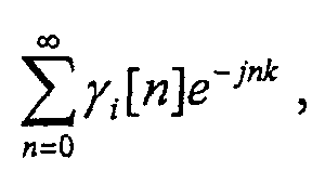
- The receiver of claim 1 said matrix U is the eigen matrix of said channels frequency-domain correlation function, which is related to said Discrete Fourier Transform of said delay function.
- The receiver of claim 1 where said matrix U, is related to a delay function that is truncated in time.
- The receiver of claim 1 where said delay function is unrelated to actual delay characteristics of said channels.
- The receiver of claim 1 where said delay function is arbitrarily selected.
- The receiver of claim 1 where said delay function is selected to be

- The receiver of claim 1 where said delay function is selected to be

Applications Claiming Priority (2)
| Application Number | Priority Date | Filing Date | Title |
|---|---|---|---|
| US535945 | 2000-03-27 | ||
| US09/535,945 US6795392B1 (en) | 2000-03-27 | 2000-03-27 | Clustered OFDM with channel estimation |
Publications (3)
| Publication Number | Publication Date |
|---|---|
| EP1139628A2 true EP1139628A2 (en) | 2001-10-04 |
| EP1139628A9 EP1139628A9 (en) | 2002-03-20 |
| EP1139628A3 EP1139628A3 (en) | 2004-01-07 |
Family
ID=24136469
Family Applications (1)
| Application Number | Title | Priority Date | Filing Date |
|---|---|---|---|
| EP20010302593 Withdrawn EP1139628A3 (en) | 2000-03-27 | 2001-03-20 | Multicarrier receiver with channel estimation, for multiple access channels |
Country Status (8)
| Country | Link |
|---|---|
| US (3) | US6795392B1 (en) |
| EP (1) | EP1139628A3 (en) |
| JP (1) | JP4620277B2 (en) |
| AR (1) | AR030199A1 (en) |
| BR (1) | BR0101099A (en) |
| CA (1) | CA2341086C (en) |
| HK (1) | HK1039420A1 (en) |
| TW (1) | TW522694B (en) |
Cited By (1)
| Publication number | Priority date | Publication date | Assignee | Title |
|---|---|---|---|---|
| US7965796B2 (en) | 2002-02-27 | 2011-06-21 | Freescale Semiconductor, Inc. | Channel estimation in a radio receiver |
Families Citing this family (49)
| Publication number | Priority date | Publication date | Assignee | Title |
|---|---|---|---|---|
| US7952511B1 (en) | 1999-04-07 | 2011-05-31 | Geer James L | Method and apparatus for the detection of objects using electromagnetic wave attenuation patterns |
| US6795392B1 (en) * | 2000-03-27 | 2004-09-21 | At&T Corp. | Clustered OFDM with channel estimation |
| JP2001339328A (en) * | 2000-05-25 | 2001-12-07 | Communication Research Laboratory | Receiving device, receiving method, and information recording medium |
| US6990061B2 (en) * | 2000-05-31 | 2006-01-24 | Interuniversitair Micro-Elektronica Centrum | Method and apparatus for channel estimation |
| EP1170897B1 (en) * | 2000-07-05 | 2020-01-15 | Wi-Fi One Technologies International Limited | Pilot pattern design for a STTD scheme in an OFDM system |
| JP3639521B2 (en) * | 2000-11-10 | 2005-04-20 | 株式会社ケンウッド | Diversity receiver and orthogonal frequency division multiplex signal receiving method |
| US6947748B2 (en) | 2000-12-15 | 2005-09-20 | Adaptix, Inc. | OFDMA with adaptive subcarrier-cluster configuration and selective loading |
| JP2002290367A (en) * | 2001-03-26 | 2002-10-04 | Hitachi Kokusai Electric Inc | Band division demodulation method and OFDM receiver |
| US7068592B1 (en) * | 2001-05-10 | 2006-06-27 | Conexant, Inc. | System and method for increasing payload capacity by clustering unloaded bins in a data transmission system |
| US7158563B2 (en) * | 2001-06-01 | 2007-01-02 | The Board Of Trustees Of The Leland Stanford Junior University | Dynamic digital communication system control |
| US7173991B2 (en) * | 2002-06-17 | 2007-02-06 | Hitachi, Ltd. | Methods and apparatus for spectral filtering channel estimates |
| US7161896B1 (en) * | 2002-08-12 | 2007-01-09 | Cisco Systems Wireless Networking (Australia) Pty Limited | Channel estimation in a multicarrier radio receiver |
| AU2003268227A1 (en) * | 2002-08-28 | 2004-03-19 | Zyray Wireless, Inc. | Iterative multi-stage detection technique for a diversity receiver having multiple antenna elements |
| KR100471538B1 (en) * | 2002-09-18 | 2005-02-21 | 한기열 | Channel estimation and symbol timing decision apparatus and method of ofdm system |
| US7187940B2 (en) * | 2003-07-31 | 2007-03-06 | Motorola, Inc. | Decorrelating rake receiver apparatus and method |
| ATE494683T1 (en) | 2003-08-29 | 2011-01-15 | Nat Inst Inf & Comm Tech | TRANSMITTER DEVICE, RECEIVER DEVICE, TRANSMISSION METHOD, RECEPTION METHOD AND PROGRAM |
| US7570695B2 (en) * | 2003-12-18 | 2009-08-04 | Intel Corporation | Method and adaptive bit interleaver for wideband systems using adaptive bit loading |
| CN1922789B (en) * | 2004-01-30 | 2011-09-07 | 拉瓦尔大学 | Multi-user adaptive array receiver and method |
| GB0403762D0 (en) * | 2004-02-20 | 2004-03-24 | Qinetiq Ltd | Frequency compensated communications reception |
| US7702045B2 (en) * | 2004-08-31 | 2010-04-20 | Theta Microelectronics, Inc. | Method for estimating wireless channel parameters |
| US7081597B2 (en) * | 2004-09-03 | 2006-07-25 | The Esab Group, Inc. | Electrode and electrode holder with threaded connection |
| US7573851B2 (en) | 2004-12-07 | 2009-08-11 | Adaptix, Inc. | Method and system for switching antenna and channel assignments in broadband wireless networks |
| US7609773B2 (en) | 2005-04-18 | 2009-10-27 | Qualcomm Incorporated | Method of determining the location of the FFT window and the delay spread for the platinum broadcast channel estimator |
| US8363577B2 (en) * | 2005-05-13 | 2013-01-29 | Qualcomm Incorporated | Low complexity beamforming for multiple antenna systems |
| JP2007006264A (en) * | 2005-06-24 | 2007-01-11 | Toshiba Corp | Diversity receiver |
| US20070055784A1 (en) * | 2005-09-08 | 2007-03-08 | Pancholi Ketan P | Method to reduce the learning curve of a transmission control protocol connection |
| US7974360B2 (en) | 2006-05-24 | 2011-07-05 | Qualcomm Incorporated | Multi input multi output (MIMO) orthogonal frequency division multiple access (OFDMA) communication system |
| US8428197B2 (en) | 2006-06-01 | 2013-04-23 | Qualcomm Incorporated | Enhanced channel estimation for communication system receiver |
| US7898478B2 (en) * | 2007-02-28 | 2011-03-01 | Samsung Electronics Co., Ltd. | Method and system for analog beamforming in wireless communication systems |
| US7830984B2 (en) | 2007-03-30 | 2010-11-09 | Hong Kong Applied Science And Technology Research Institute Co., Ltd. | OFDM/OFDMA channel estimation |
| US7881392B2 (en) * | 2007-03-30 | 2011-02-01 | Hong Kong Applied Science And Technology Research Institute Co., Ltd. | OFDM/OFDMA timing synchronization using non-consecutive pilot subcarrier assignment |
| US7940848B2 (en) * | 2007-04-02 | 2011-05-10 | Infineon Technologies Ag | System having an OFDM channel estimator |
| US7714783B2 (en) * | 2007-08-02 | 2010-05-11 | Samsung Electronics Co., Ltd. | Method and system for analog beamforming in wireless communications |
| US8249513B2 (en) * | 2007-08-13 | 2012-08-21 | Samsung Electronics Co., Ltd. | System and method for training different types of directional antennas that adapts the training sequence length to the number of antennas |
| US8411805B1 (en) * | 2007-08-14 | 2013-04-02 | Marvell International Ltd. | Joint estimation of channel and preamble sequence for orthogonal frequency division multiplexing systems |
| US7714781B2 (en) * | 2007-09-05 | 2010-05-11 | Samsung Electronics Co., Ltd. | Method and system for analog beamforming in wireless communication systems |
| US20090121935A1 (en) * | 2007-11-12 | 2009-05-14 | Samsung Electronics Co., Ltd. | System and method of weighted averaging in the estimation of antenna beamforming coefficients |
| US8165595B2 (en) * | 2008-01-25 | 2012-04-24 | Samsung Electronics Co., Ltd. | System and method for multi-stage antenna training of beamforming vectors |
| US8051037B2 (en) * | 2008-01-25 | 2011-11-01 | Samsung Electronics Co., Ltd. | System and method for pseudorandom permutation for interleaving in wireless communications |
| US8280445B2 (en) * | 2008-02-13 | 2012-10-02 | Samsung Electronics Co., Ltd. | System and method for antenna training of beamforming vectors by selective use of beam level training |
| JP5029439B2 (en) * | 2008-03-14 | 2012-09-19 | 富士通株式会社 | Wireless communication apparatus and interference cancellation method |
| US8417191B2 (en) * | 2008-03-17 | 2013-04-09 | Samsung Electronics Co., Ltd. | Method and system for beamforming communication in high throughput wireless communication systems |
| US8478204B2 (en) * | 2008-07-14 | 2013-07-02 | Samsung Electronics Co., Ltd. | System and method for antenna training of beamforming vectors having reuse of directional information |
| MX2011010064A (en) * | 2009-03-27 | 2012-01-12 | Aclara Power Line Systems Inc | DETECTION OF UNDER FREQUENCY / UNDERVOLTAGE IN A DEMANDED RESPONSE UNIT. |
| US8879523B2 (en) * | 2009-06-05 | 2014-11-04 | Broadcom Corporation | Management frame directed cluster assignment within multiple user, multiple access, and/or MIMO wireless communications |
| US8885535B2 (en) * | 2009-06-05 | 2014-11-11 | Broadcom Corporation | Management frame map directed operational parameters within multiple user, multiple access, and/or MIMO wireless communications |
| CN102158437B (en) * | 2010-02-11 | 2014-07-02 | 富士通株式会社 | Channel frequency domain correlation calculation device and method |
| US10038487B2 (en) * | 2013-05-29 | 2018-07-31 | Alcatel Lucent | CSI feedback method and apparatus in large scale antenna system |
| US11316554B2 (en) * | 2019-06-05 | 2022-04-26 | Rincon Research Corporation | Multi-antenna detection, localization, and filtering of complex time-and-doppler-shifted signals |
Family Cites Families (18)
| Publication number | Priority date | Publication date | Assignee | Title |
|---|---|---|---|---|
| JP3563421B2 (en) * | 1993-08-25 | 2004-09-08 | 株式会社東芝 | Wireless communication device |
| US5481570A (en) * | 1993-10-20 | 1996-01-02 | At&T Corp. | Block radio and adaptive arrays for wireless systems |
| CA2302289C (en) * | 1996-08-29 | 2005-11-08 | Gregory G. Raleigh | Spatio-temporal processing for communication |
| JP3559428B2 (en) * | 1997-06-26 | 2004-09-02 | 株式会社東芝 | Receiver |
| JP3724940B2 (en) * | 1998-01-08 | 2005-12-07 | 株式会社東芝 | OFDM diversity receiver |
| JP3718337B2 (en) * | 1998-01-08 | 2005-11-24 | 株式会社東芝 | Adaptive variable directional antenna |
| US6618454B1 (en) * | 1998-02-06 | 2003-09-09 | At&T Corp. | Diversity coded OFDM for high data-rate communication |
| US6327314B1 (en) * | 1998-04-01 | 2001-12-04 | At&T Corp. | Method and apparatus for channel estimation for multicarrier systems |
| US5973642A (en) * | 1998-04-01 | 1999-10-26 | At&T Corp. | Adaptive antenna arrays for orthogonal frequency division multiplexing systems with co-channel interference |
| US6240141B1 (en) * | 1998-05-09 | 2001-05-29 | Centillium Communications, Inc. | Lower-complexity peak-to-average reduction using intermediate-result subset sign-inversion for DSL |
| US6795424B1 (en) * | 1998-06-30 | 2004-09-21 | Tellabs Operations, Inc. | Method and apparatus for interference suppression in orthogonal frequency division multiplexed (OFDM) wireless communication systems |
| US6266644B1 (en) * | 1998-09-26 | 2001-07-24 | Liquid Audio, Inc. | Audio encoding apparatus and methods |
| JP2000183789A (en) * | 1998-12-10 | 2000-06-30 | Matsushita Electric Ind Co Ltd | Digital television broadcast receiver |
| JP2001016180A (en) * | 1999-06-29 | 2001-01-19 | Mitsubishi Electric Corp | Orthogonal polarization frequency multiplexed signal receiver |
| US6298035B1 (en) * | 1999-12-21 | 2001-10-02 | Nokia Networks Oy | Estimation of two propagation channels in OFDM |
| US6473467B1 (en) * | 2000-03-22 | 2002-10-29 | Qualcomm Incorporated | Method and apparatus for measuring reporting channel state information in a high efficiency, high performance communications system |
| US6795392B1 (en) * | 2000-03-27 | 2004-09-21 | At&T Corp. | Clustered OFDM with channel estimation |
| US6369758B1 (en) * | 2000-11-01 | 2002-04-09 | Unique Broadband Systems, Inc. | Adaptive antenna array for mobile communication |
-
2000
- 2000-03-27 US US09/535,945 patent/US6795392B1/en not_active Expired - Lifetime
-
2001
- 2001-03-20 BR BR0101099-9A patent/BR0101099A/en not_active Application Discontinuation
- 2001-03-20 EP EP20010302593 patent/EP1139628A3/en not_active Withdrawn
- 2001-03-21 TW TW090106553A patent/TW522694B/en not_active IP Right Cessation
- 2001-03-21 CA CA002341086A patent/CA2341086C/en not_active Expired - Lifetime
- 2001-03-22 AR ARP010101359A patent/AR030199A1/en unknown
- 2001-03-27 JP JP2001088960A patent/JP4620277B2/en not_active Expired - Fee Related
-
2002
- 2002-01-30 HK HK02100726.9A patent/HK1039420A1/en unknown
-
2004
- 2004-06-24 US US10/875,597 patent/US7369487B2/en active Active
-
2008
- 2008-05-06 US US12/151,419 patent/US8320500B2/en not_active Expired - Fee Related
Cited By (1)
| Publication number | Priority date | Publication date | Assignee | Title |
|---|---|---|---|---|
| US7965796B2 (en) | 2002-02-27 | 2011-06-21 | Freescale Semiconductor, Inc. | Channel estimation in a radio receiver |
Also Published As
| Publication number | Publication date |
|---|---|
| JP4620277B2 (en) | 2011-01-26 |
| US20090003489A1 (en) | 2009-01-01 |
| US6795392B1 (en) | 2004-09-21 |
| EP1139628A9 (en) | 2002-03-20 |
| US20040234013A1 (en) | 2004-11-25 |
| HK1039420A1 (en) | 2002-04-19 |
| EP1139628A3 (en) | 2004-01-07 |
| BR0101099A (en) | 2001-11-06 |
| CA2341086C (en) | 2006-07-11 |
| TW522694B (en) | 2003-03-01 |
| US7369487B2 (en) | 2008-05-06 |
| CA2341086A1 (en) | 2001-09-27 |
| AR030199A1 (en) | 2003-08-13 |
| US8320500B2 (en) | 2012-11-27 |
| JP2001320344A (en) | 2001-11-16 |
Similar Documents
| Publication | Publication Date | Title |
|---|---|---|
| US7369487B2 (en) | Clustered OFDM with channel estimation | |
| US11303377B2 (en) | Estimating frequency-offsets and multi-antenna channels in MIMO OFDM systems | |
| US5973642A (en) | Adaptive antenna arrays for orthogonal frequency division multiplexing systems with co-channel interference | |
| US6327314B1 (en) | Method and apparatus for channel estimation for multicarrier systems | |
| US7852906B2 (en) | Wireless communication device and channel estimation and separation method in multi input system | |
| US6647078B1 (en) | Method and device for multi-user frequency-domain channel estimation based on gradient optimization techniques | |
| US6901122B2 (en) | Method and apparatus for restoring a soft decision component of a signal | |
| US7876839B2 (en) | Receiver and method for channel estimation for multicarrier communication systems | |
| US7519125B2 (en) | Multicarrier receiver and methods of generating spatial correlation estimates for signals received with a plurality of antennas | |
| US20030099304A1 (en) | System and method for transmit diversity base upon transmission channel delay spread | |
| EP1530333A1 (en) | Method for channel estimation in a MIMO OFDM system | |
| EP1294148A1 (en) | Delay spread estimation of multipath fading channels in a OFDM receiver | |
| Auer | Channel estimation in two dimensions for OFDM systems with multiple transmit antennas | |
| US7450490B2 (en) | Channel estimation using the guard interval of a multicarrier signal | |
| Sarperi et al. | Multiuser detection and channel estimation in MIMO OFDM systems via blind source separation | |
| Auer | Channel estimation for OFDM systems with multiple transmit antennas by filtering in time and frequency | |
| Sun et al. | A subspace-based channel identification algorithm for forward link in space-time coded MC-CDMA systems | |
| Budsabathon et al. | On a novel pre-FFT OFDM adaptive antenna array for delayed signal suppression | |
| Chang et al. | Cancellation of ICI by Doppler effect in OFDM systems | |
| Mahapriya et al. | Estimation of Channel for Multipath Transmission in Wireless Communication Using OFDM | |
| Alkhawaldeh et al. | A robust pilot-symbol-aided channel estimator for OFDM wireless communications | |
| Bocquet et al. | VISA MIMO OFDM transmit scheme for wireless communications | |
| Li et al. | A novel fractionally spaced frequency domain equalization scheme for single carrier cyclic prefix assisted MIMO-CDMA systems | |
| Panayırcı et al. | Maximum A Posteriori Channel Estimation for Space-Frequency Block Coded OFDM Systems | |
| GB2478604A (en) | Wireless communications channel estimation |
Legal Events
| Date | Code | Title | Description |
|---|---|---|---|
| PUAI | Public reference made under article 153(3) epc to a published international application that has entered the european phase |
Free format text: ORIGINAL CODE: 0009012 |
|
| AK | Designated contracting states |
Kind code of ref document: A2 Designated state(s): AT BE CH CY DE DK ES FI FR GB GR IE IT LI LU MC NL PT SE TR |
|
| AX | Request for extension of the european patent |
Free format text: AL;LT;LV;MK;RO;SI |
|
| PUAL | Search report despatched |
Free format text: ORIGINAL CODE: 0009013 |
|
| AK | Designated contracting states |
Kind code of ref document: A3 Designated state(s): AT BE CH CY DE DK ES FI FR GB GR IE IT LI LU MC NL PT SE TR |
|
| AX | Request for extension of the european patent |
Extension state: AL LT LV MK RO SI |
|
| STAA | Information on the status of an ep patent application or granted ep patent |
Free format text: STATUS: THE APPLICATION IS DEEMED TO BE WITHDRAWN |
|
| 18D | Application deemed to be withdrawn |
Effective date: 20031001 |
|
| REG | Reference to a national code |
Ref country code: HK Ref legal event code: WD Ref document number: 1039420 Country of ref document: HK |