EP1139591A2 - Method and receiver for receiving Digital Audio Broadcast (DAB) - Google Patents
Method and receiver for receiving Digital Audio Broadcast (DAB) Download PDFInfo
- Publication number
- EP1139591A2 EP1139591A2 EP01302889A EP01302889A EP1139591A2 EP 1139591 A2 EP1139591 A2 EP 1139591A2 EP 01302889 A EP01302889 A EP 01302889A EP 01302889 A EP01302889 A EP 01302889A EP 1139591 A2 EP1139591 A2 EP 1139591A2
- Authority
- EP
- European Patent Office
- Prior art keywords
- coded signal
- magnitude
- received coded
- signal
- received
- Prior art date
- Legal status (The legal status is an assumption and is not a legal conclusion. Google has not performed a legal analysis and makes no representation as to the accuracy of the status listed.)
- Withdrawn
Links
- 238000000034 method Methods 0.000 title claims abstract description 39
- 230000002040 relaxant effect Effects 0.000 claims abstract description 11
- 230000005684 electric field Effects 0.000 description 24
- 101100513046 Neurospora crassa (strain ATCC 24698 / 74-OR23-1A / CBS 708.71 / DSM 1257 / FGSC 987) eth-1 gene Proteins 0.000 description 10
- 230000007423 decrease Effects 0.000 description 5
- 238000010586 diagram Methods 0.000 description 3
- 230000001172 regenerating effect Effects 0.000 description 2
- 230000003321 amplification Effects 0.000 description 1
- 230000002238 attenuated effect Effects 0.000 description 1
- 230000005540 biological transmission Effects 0.000 description 1
- 230000003247 decreasing effect Effects 0.000 description 1
- 238000001514 detection method Methods 0.000 description 1
- 239000000284 extract Substances 0.000 description 1
- 238000003199 nucleic acid amplification method Methods 0.000 description 1
- 230000008707 rearrangement Effects 0.000 description 1
Images


Classifications
-
- H—ELECTRICITY
- H04—ELECTRIC COMMUNICATION TECHNIQUE
- H04H—BROADCAST COMMUNICATION
- H04H40/00—Arrangements specially adapted for receiving broadcast information
- H04H40/18—Arrangements characterised by circuits or components specially adapted for receiving
-
- H—ELECTRICITY
- H04—ELECTRIC COMMUNICATION TECHNIQUE
- H04H—BROADCAST COMMUNICATION
- H04H60/00—Arrangements for broadcast applications with a direct linking to broadcast information or broadcast space-time; Broadcast-related systems
- H04H60/35—Arrangements for identifying or recognising characteristics with a direct linkage to broadcast information or to broadcast space-time, e.g. for identifying broadcast stations or for identifying users
- H04H60/38—Arrangements for identifying or recognising characteristics with a direct linkage to broadcast information or to broadcast space-time, e.g. for identifying broadcast stations or for identifying users for identifying broadcast time or space
- H04H60/41—Arrangements for identifying or recognising characteristics with a direct linkage to broadcast information or to broadcast space-time, e.g. for identifying broadcast stations or for identifying users for identifying broadcast time or space for identifying broadcast space, i.e. broadcast channels, broadcast stations or broadcast areas
- H04H60/43—Arrangements for identifying or recognising characteristics with a direct linkage to broadcast information or to broadcast space-time, e.g. for identifying broadcast stations or for identifying users for identifying broadcast time or space for identifying broadcast space, i.e. broadcast channels, broadcast stations or broadcast areas for identifying broadcast channels
Definitions
- the present invention relates to method and device for receiving DAB (digital audio broadcast).
- the DAB can provide high-quality digital audio programs for a receiver, in particular, on a mobile unit.
- a DAB receiver includes an antenna for receiving a signal carrying DAB data, an amplification system for amplifying the received signal, a decoding system for decoding the received signal into digital data, and a reproducing system for reproducing MPEG audio data contained in the digital data and outputting the same to a speaker.
- the DAB receiver further includes a search system for searching a broadcast signal, within a predetermined frequency range, which can be decoded into digital data.
- the decoding system fails in decoding the signal.
- the searching system if it receives a relatively strong signal, it attempts to decode the signal. However, if the received signal includes relatively strong noise components, but does not include decodable or reproducible data, even if the decoding operation is normally performed, the reproducing system fails to reproduce the audio data.
- the search system continues searching a frequency band until an appropriate frequency can be detected (i.e., until the audio data is reproduced). Therefore, in the conventional DAB receiver, signals are decoded each time a frequency, which may contain undecodable signal or noise components, is detected, until the reproduction of the audio data is successfully performed. As a result of such a configuration, the conventional DAB receiver usually takes a relatively long time, from starting the searching process, until the reproduction of the audio data.
- a method of receiving and decoding a coded signal for a digital broadcast which is provided with the steps of:
- the condition of the received signal is checked, before it is decoded into digital data, to determine the received signal is decodable/reproducible. Therefore, unnecessary decoding/reproducing operations during the search operation can be avoided, and a stable frequency can be caught and the data is reproduced quickly.
- the predetermined condition may includes an upper limit of the magnitude of the received coded signal
- the step of judging may include a step of examining whether a magnitude of the received coded signal is lower than the upper limit of the magnitude of the received coded signal.
- the step of judging judges that the received coded signal is decodable when the magnitude of the received coded signal is lower than the upper limit.
- the step of relaxing may include a step of raising the upper limit.
- the predetermined condition may include a lower limit of the magnitude of the received coded signal
- the step of judging may include a step of examining whether a magnitude of the received coded signal is greater than the lower limit of the magnitude of the received coded signal.
- the step of judging judges that the received coded signal is decodable when the magnitude of the received coded signal is greater than the lower limit.
- the step of relaxing may include a step of lowering the lower limit.
- the predetermined condition may include a threshold of the amount of noise components included in the received coded signal
- the step of judging may include a step of examining whether the amount of noise components included in the received coded signal is lower than the threshold of the amount of the noise components included in the received coded signal.
- the step of judging judges that the received coded signal is decodable when the amount of noise components is lower than the threshold.
- the step of relaxing may include a step of increasing the threshold.
- a digital broadcast receiver for receiving a digital broadcast may be configured to employ any one of the methods described above.
- a digital broadcast receiver for receiving a digital broadcast, which is provided with
- a DAB (Digital Audio Broadcast) receiver according to an embodiment of the invention will be described with reference to the drawings attached hereto, in which:
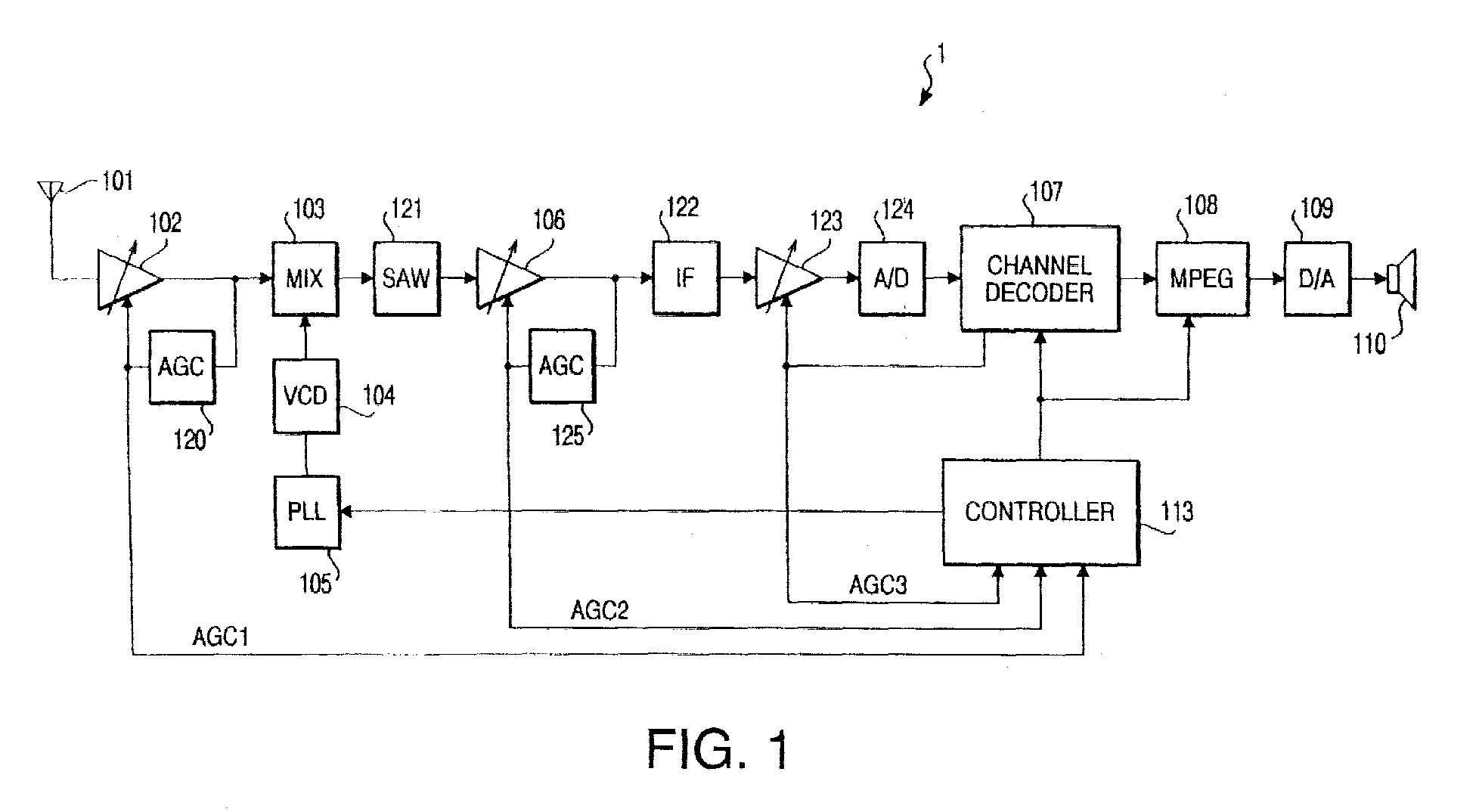
- Fig. 1 is a block diagram showing a configuration of the DAB receiver 1.
- a DAB signal is received by an antenna 101, and is input to a high frequency amplifier 102, which will be referred to as a first amplifier 102.
- the output of the high frequency amplifier 102 is input to a mixing circuit 103, and also input to a first AGC (Automatic Gain Controlling) circuit 120.
- the first amplifier 102 is configured to change the gain thereof in accordance with the voltage applied to a gain control terminal thereof.
- the first AGC circuit 120 outputs a first AGC voltage V AGC1 , which is applied to the gain control terminal of the first amplifier 102.
- the first AGC circuit 120 operates to output the first AGC voltage V AGC1 such that the magnitude of the signal output from the first amplifier 102 has a constant magnitude Vp with respect to a predetermined magnitude range of the signal input to the first amplifier 102.
- the upper limit and the lower limit of the first AGC voltage V AGC1 are 0 and V1 (>0), respectively.
- the gain of the first amplifier 102 is the maximum value Gmax when the first AGC voltage V AGC1 is 0, while the gain is the minimum value Gmin when the first AGC voltage V AGC1 is V1.
- Fig. 2A shows a relationship between the electrical field strength of the received signal (i.e., the magnitude of the signal input to the first amplifier 102) and the magnitude of the output of the first amplifier 102.
- a first range i.e., 0 ⁇ E ⁇ Eth1 where the magnitude of the signal input to the first amplifier 102 is relatively small
- the magnitude of the output signal does not reach the predetermined constant level V1 even if the gain is Gmax. Therefore, in the first range (i.e., the electrical field strength E ⁇ a first threshold Eth1), the magnitude of the output signal varies, in a range lower than the constant level Vp, in accordance with the magnitude of the input signal.
- the gain decreases from the Gmax as the electrical field strength increases, and when the electrical field strength reaches Emax, the gain becomes Gmin.
- Eth1 ⁇ E ⁇ Emax which will be referred to as a second range, the magnitude of the output signal is maintained to be the constant value Vp regardless of the magnitude of the input signal.
- the magnitude of the output signal varies, in a range greater than the predetermined level Vp, in accordance with the magnitude of the input signal.
- the output characteristic of the first amplifier 102 has the first range, where the gain is Gmax, the second range where the output level is Vp, and the third range where the gain is Gmin.
- the gain of the first amplifier 102 can be arbitrarily set within a range from Gmax to Gmin ( ⁇ Gmax), inclusively, then the third range does not exist.
- the gain Gmin may have a certain value so that a controllable range of the gain is not unnecessarily widened.
- Fig. 2B shows a relationship between the electrical field strength of the received signal and the first AGC voltage V AGC1 output by the first AGC circuit 120.
- the first AGC voltage V AGC1 is V1 in the first range (i.e., the gain of the first amplifier 102 is Gmax), and, in the second range, the first AGC voltage VAGC1 decreases from the upper limit V1 to the lower limit 0 (i.e., the gain of the first amplifier 102 decreases from Gmax to Gmin) as the electrical field strength E increases from the first threshold Eth1 to the maximum threshold Emax.
- the other input terminal of the mixing circuit 103 is connected with a local oscillator 104.
- the first mixing circuit 103 converts a desired DAB signal frequency into an IF (intermediate frequency) signal in accordance with the frequency output by the local oscillator 104, and outputs the converted signal to a SAW filter 121.
- the SAW filter 121 filters the frequency components other than the desired DAB signal frequency, and outputs the desired DAB frequency component to an intermediate frequency amplifier (which will be referred to as a second amplifier) 106.
- a control circuit 113 sets a frequency division ratio in a PLL circuit 105, and changes the frequency of the local oscillator 104.
- the second amplifier 106 is configured to have a gain control terminal and the gain thereof is changed in accordance with the voltage (i.e., a second AGC voltage) applied to the gain control terminal.
- a second AGC circuit 125 outputs the second AGC voltage V AGC2 in accordance with the output of the second amplifier 106.
- the second AGC voltage V AGC2 is applied to the gain control terminal of the second amplifier 106.
- Fig. 3A is a graph showing a relationship between the output of the first amplifier 102, which is input to the second amplifier 106, and the output of the second amplifier 106. As shown in Fig. 2A, the magnitude of the output of the first amplifier 102 increases from 0 to Vp in the first range, and is maintained at Vp in the second range. As aforementioned, according to the embodiment, the third range will not be considered.
- the second AGC circuit 125 operates to output the second AGC voltage V AGC2 such that when the magnitude of the signal input to the second amplifier 106 is in a range from 0 to a predetermined voltage Vr, which is smaller than Vp, the gain of the second amplifier is the maximum value G'max, and that when the magnitude of the input signal is in a range from Vr to Vp, the magnitude of the output signal is a constant value V'r. It should be noted that when the magnitude of the input signal is in the range from 0 to Vr, the output of the second amplifier 106 varies in a range from 0 to V'r.
- the predetermined voltage V'r is determined to correspond to the output voltage of the first amplifier 102 when the electrical field strength E of the input signal is a second threshold value Eth2, as shown in Fig. 2A. Therefore, when the magnitude of the signal input to the first amplifier 102 is less than the second threshold Eth2, the magnitude of the output of the first amplifier 102 is less than Vr, which is input to the second amplifier 106. Then, as shown in Fig. 3A, the magnitude of the signal output from the second amplifier 106 is less than V'r.
- Fig. 3B is a graph showing a relationship between the magnitude of the output of the first amplifier 102 and the second AGC voltage V AGC2 .
- V AGC2 V2
- the second AGC voltage V AGC2. is decreased as the magnitude of the output of the first amplifier 102 increases so that the magnitude of the output signal of the second amplifier 106 is the constant value V'r. While the output of the first amplifier 102 increases from Vr to Vp, the gain of the second amplifier 102 decreases from the maximum value G'max to the minimum value G'min.
- the signal output from the second amplifier 106 is. transmitted to the AGC amplifier (which will be referred to as a third amplifier) 123, with the frequency components other than predetermined frequency components being cut by an IF (intermediate frequency) filter 122.
- the AGC amplifier which will be referred to as a third amplifier
- the third amplifier 123 is also a variable gain amplifier having a gain control terminal. To the gain control terminal of the third amplifier 123, a third AGC voltage V AGC3 is applied by a channel decoder 107. The third AGC voltage V AGC3 is controlled such that the magnitude of the signal output from the third amplifier 123 is constant. The output signal of the third amplifier 123 is input to an A/D converter 124, which converts the input to signal to digital data. The digital data is transmitted from the A/D converter 124 to the channel decoder 107.
- Fig. 4A shows a relationship between the magnitude of the output of the second amplifier 106 and the output of the third amplifier 123
- Fig. 4B shows a relationship between the magnitude of the input signal of the third amplifier 123 and the third AGC voltage V AGC3
- the magnitude of the output signal of the second amplifier 106 increases from 0 to V'r as the magnitude of the output signal of the first amplifier increases from 0 to Vr, and is the constant value V'r when the magnitude of the output of the first amplifier 102 is in a range between Vr and Vp.
- the third AGC voltage V AGC3 decreases as the magnitude of the output of the second amplifier 106 changes from 0 to Vr so that the output of the third amplifier 123 is constant.
- the third AGC voltage V AGC3 is 0, which is the minimum value.
- the channel decoder 107 is controlled by a control circuit 113 to select data corresponding to a DAB program designated by a user, and to transmit the selected data to an MPEG audio decoder 108.
- the output of the MPEG audio decoder 108 is transmitted to a D/A converter 109, which converts the input data into an analog signal. Then, the analog signal is applied to a speaker 110, thereby an audio service of a DAB being finally provided to the user.
- Fig. 5 shows an exemplary configuration of the channel decoder 107.
- the digital signal output by the A/D converter 124 is OFDM-decoded by an FFT circuit 131. Then, a plurality of pieces of the data obtained by OFDM-decoding are re-arranged in order using a de-interleave circuit 132. At this time, the data in a transmission frame is grouped for each service (i.e., DAB program) as shown in Fig. 11. After re-arrangement of the DAB data in order using the de-interleave circuit 132, an error correction is performed by a Viterbi decoder 133. Then, the control circuit 113 extracts necessary service data, which is transmitted to the MPEG audio decoder 108.
- DAB program i.e., DAB program
- the output of the FFT circuit 131 is also input to a synchronization control unit 134, where a frequency shift, an FFT window shift, and a clock frequency shift are corrected, thereby the synchronization both in frequency and time being established.
- a digital AGC control unit 135 receives the output of the third amplifier 123, which is converted into the digital data by the A/D converter 124, through the FFT circuit 131, and outputs the third AGC voltage V AGC3 to the third amplifier 123.
- Figs. 6A-6C show relationships between the electrical field strength of the received signal and the first through third AGC voltages V AGC1 , V AGC2 and V AGC3 .
- Figs. 6A-6C are similar to Figs. 2B, 3B and 4B, respectively, except that the horizontal axes thereof represent the electrical field strength of the received signal.
- the first AGC circuit 120 operates such that the magnitude of the output of the first amplifier 102 is constant when the electrical field strength E is Eth1 ⁇ E ⁇ Eth2, and the second AGC circuit 125 operates such that the output of the second amplifier 106 is constant when Eth2 ⁇ E ⁇ Eth1. Further, the digital AGC control unit 135 operates such that the output of the third amplifier 123 is constant when E ⁇ Eth2. Thus, if E ⁇ Emax, the magnitude of the signal input to the A/D converter 124 is constant.
- the electrical field strength E of the received signal can be determined. Therefore, based on the values of the first through third AGC voltages V AGC1 , V AGC2 and V AGC3 , whether a DAB signal is to be processed can be determined during the frequency search, before the decoding operation is performed.
- the first through third AGC voltages V AGC1 , V AGC2 and V AGC3 are input to the controller 113, as shown in Fig. 1.
- the controller 113 determines that the signal is too strong and cannot be decoded. Further, if the electrical field strength of the received signal is less than a lower limit E LL (>0), the controller 113 determines that the signal is too weak and cannot be decoded.
- the controller 113 determines that the signal is too strong and cannot be decoded. As shown in Fig. 6C, if the third AGC voltage V AGC3 is greater than a voltage V LL which corresponds to the lower limit E LL of the electrical field strength, the controller 113 determines that the signal is too weak and cannot be decoded.
- degree of noise components in particular an adjacent interference DAB signal
- the controller 113 determines that the signal cannot be received in good condition, and the decoding procedure for the signal is not performed. In this case, another frequency search is performed.
- FIGs. 7A and 7B show the magnitude of the received signal and the first and second AGC voltages V AGC1 and V AGC2 , respectively.
- the first AGC voltage V AGC1 is Va (> 0), and the second AGC voltage V AGC2 is 0. That is, points a in Figs. 7A and 7B represent the status of the received signal. If the noise components are included in the received signal, then even if the first AGC voltage V AGC1 is Va, since the magnitude of the signal output by the first amplifier 102 is lowered as the noise components are well attenuated by the SAW filter 104, the magnitude of the signal input to the second amplifier is less than Va. In this case, the second AGC circuit 125 outputs V'a as the second AGC voltage V AGC2 .
- the controller 113 judges that the electrical field strength of the received signal is Eth2 ⁇ E ⁇ Eth1. That is, as shown in Fig. 7B, from the second AGC voltage V AGC2 , which is V'a, the electrical field strength of the received signal is judged to be E'a. Therefore, Ea - E'a is obtained as the amount ⁇ representing the noise components.
- V'a/Va is greater.
- Fig. 8 is a graph showing a boundary condition of decodable/undecodable signal.
- the horizontal axis represents the first AGC voltage V AGC1
- the vertical axis represents the second AGC voltage V AGC2 .
- a line L in the graph represents the boundary line. Based on a position of a point P identified by the voltages Va and V'a with respect to the boundary line L , whether the received signal is decodable or undecodable is judged.
- the boundary line L has an inclination of ⁇ , which is intrinsic to individual receivers, and if the inclination ⁇ is greater, the receiver can decode the received signal even if the amount ⁇ of the noise components is large.
- Fig. 9 is a flowchart illustrating a frequency search procedure according to the embodiment of the present invention.
- a variable PLL_Freq is set to a predetermined initial search frequency PLL_Min, and control proceeds to S101.
- S101 it is determined whether the PLL is locked at the frequency PLL_Freq. If the PLL is locked (S101: YES), then control proceeds to S102. If the PLL is not locked (S101: NO), then control proceeds to S110.
- Fig. 10 shows the condition check procedure at S102 of Fig. 9 in detail.
- such a frequency is stored in the memory, and in the succeeding searching procedures, for the frequencies stored in the memory, it is determined that the received signal does not satisfy the required condition. That is, if the frequency PLL_Freq is the frequency stored in the memory, control proceeds to S110.
- the first AGC voltage V AGC1 is compared with the voltage V UL corresponding to the upper limit E UL of the electrical field strength of the received signal. If V ACG1 ⁇ V UL , the received signal is too strong and control proceeds to S110.
- the third AGC voltage V AGC3 is compared with the voltage V LL corresponding to the lower limit E LL of the electrical field strength of the received signal. If V AGC3 > V L L, the received signal is too weak and control proceeds to S110.
- the ratio of the second AGC voltage V AGC 2 to the first AGC voltage V AGC1 is compared with the inclination ⁇ of the boundary line shown in Fig. 8 to determine whether the received signal is decodable. If V AGC2 /V AGC1 ⁇ ⁇ , then the signal is decodable and control proceeds to S103. If V AGC2 /V AGC1 > ⁇ , the magnitude of the noise components is too strong, and the signal cannot be decoded. In this case, the frequency represented by PLL_Freq is stored in the memory of the controller 113 (S209), and then control proceeds to S110.
- the synchronizing control unit 134 examines the signal input to the channel decoder 107 to judge whether the time synchronization is established. If the time synchronization is established (S103: YES), control proceeds to S105. Otherwise, control proceeds to S110.
- step S105 it is judged whether the digital data input to the MPEG audio decoder 108 can be correctly regenerated by the MPEG audio decoder 108. If it is judged that the MPEG audio decoder 108 can correctly execute the regenerating process (S105: YES), then control proceeds to step S110. Otherwise (S105: NO), in order to prevent the decoding/regenerating procedure of the current frequency PLL_Freq in the succeeding procedures after the condition is changed, the frequency PLL_Freq is stored in the memory of the controller 113.
- step S110 it is judged whether the variable PLL_Freq has reached a maximum search frequency PLL_Max.
- step S111 at least one of the limit/threshold values referred to in S102 is changed, and the criteria for determining whether the magnitude of the received signal at the frequency PLL_Freq is in a predetermined range and whether the noise components included in the received signal at the frequency PLL_Freq are removable is relaxed, and then control proceeds to S112. Specifically, in S111, at least one of (1) lowering the lower limit V UL of the first AGC voltage V AGC1 , (2) raising the upper limit V LL of the third AGC voltage V AGC3 , and (3) increasing the inclination ⁇ .
- limit/threshold values may be changed in various ways in accordance with or regardless of the condition of the received signal. For example, if the first AGC voltages V AGC1 corresponding the received signals tend to be lower than the lower limit V UL , it is preferable that the lower limit V UL is lowered. Further, if the third AGC voltages V AGC3 corresponding the received signals tend to be greater than the upper limit V LL , it is preferable that the upper limit V LL is raised. Furthermore, if the received signals are tend to be judged to be undecodable due to the noise components included therein, it is preferable that the inclination ⁇ that is used as the threshold value is increased.
- step S112 the variable PLL_Freq is reset to PLL_Min, and control returns to S101. It should be noted that, once the process in S112 has been performed, even if the frequency PLL_Freq is locked in S101, the input condition is judged to be NG in S102 if (1) the frequency PLL_Freq is a frequency which was judged not to be reproducible, or (2) the frequency PLL_Freq is a frequency which was judged that the noise components were removable. In such a case, control proceeds from S102 to S110.
- the condition of the received signal is checked, before it is decoded into digital data, to determine the received signal is decodable/reproducible. Therefore, unnecessary decoding/reproducing operations during the search operation can be avoided, and a stable frequency can be caught and the data is reproduced quickly.
Landscapes
- Engineering & Computer Science (AREA)
- Signal Processing (AREA)
- Circuits Of Receivers In General (AREA)
Abstract
Description
- The present invention relates to method and device for receiving DAB (digital audio broadcast).
- Recently, the standardization of the DAB, in which audio data is broadcast in digital form, has made progress. The DAB can provide high-quality digital audio programs for a receiver, in particular, on a mobile unit.
- Generally, a DAB receiver includes an antenna for receiving a signal carrying DAB data, an amplification system for amplifying the received signal, a decoding system for decoding the received signal into digital data, and a reproducing system for reproducing MPEG audio data contained in the digital data and outputting the same to a speaker.
- Typically, the DAB receiver further includes a search system for searching a broadcast signal, within a predetermined frequency range, which can be decoded into digital data.
- When the electric field strength of a signal which is to be decoded into digital data does not satisfy a predetermined condition, the decoding system fails in decoding the signal.
- Further, in the conventional DAB receiver, if the searching system receives a relatively strong signal, it attempts to decode the signal. However, if the received signal includes relatively strong noise components, but does not include decodable or reproducible data, even if the decoding operation is normally performed, the reproducing system fails to reproduce the audio data.
- Generally, the search system continues searching a frequency band until an appropriate frequency can be detected (i.e., until the audio data is reproduced). Therefore, in the conventional DAB receiver, signals are decoded each time a frequency, which may contain undecodable signal or noise components, is detected, until the reproduction of the audio data is successfully performed. As a result of such a configuration, the conventional DAB receiver usually takes a relatively long time, from starting the searching process, until the reproduction of the audio data.
- It is therefore an object of the invention to provide an improved DAB receiving device and a DAB receiving method, which is capable of searching an appropriate frequency within only a short period of time after a search process is started.
- For the object, according to an aspect of the invention, there is provided a method of receiving and decoding a coded signal for a digital broadcast, which is provided with the steps of:
- performing steps (1) and (2) below with sequentially
changing a frequency of a coded signal to be received
within a predetermined frequency range;
- (1) judging whether a received coded signal is decodable by examining whether the received coded signal satisfies a predetermined condition, and
- (2) decoding the received coded signal only when the received coded signal is judged to be decodable; and
- relaxing the predetermined condition and repeating the step of performing.
-
- With this configuration, the condition of the received signal is checked, before it is decoded into digital data, to determine the received signal is decodable/reproducible. Therefore, unnecessary decoding/reproducing operations during the search operation can be avoided, and a stable frequency can be caught and the data is reproduced quickly.
- Further, if the search operation, within a predetermined frequency range, under a predetermined condition fails, the condition is relaxed and the search operation is repeated. Therefore, it is likely that an appropriate frequency can be detected.
- Optionally, the predetermined condition may includes an upper limit of the magnitude of the received coded signal, and the step of judging may include a step of examining whether a magnitude of the received coded signal is lower than the upper limit of the magnitude of the received coded signal. In this case, the step of judging judges that the received coded signal is decodable when the magnitude of the received coded signal is lower than the upper limit. In this case, the step of relaxing may include a step of raising the upper limit.
- Optionally or alternatively, the predetermined condition may include a lower limit of the magnitude of the received coded signal, and the step of judging may include a step of examining whether a magnitude of the received coded signal is greater than the lower limit of the magnitude of the received coded signal. In this case, the step of judging judges that the received coded signal is decodable when the magnitude of the received coded signal is greater than the lower limit. In this case, the step of relaxing may include a step of lowering the lower limit.
- Further optionally or alternatively, the predetermined condition may include a threshold of the amount of noise components included in the received coded signal, and the step of judging may include a step of examining whether the amount of noise components included in the received coded signal is lower than the threshold of the amount of the noise components included in the received coded signal. In this case, the step of judging judges that the received coded signal is decodable when the amount of noise components is lower than the threshold. In this case, the step of relaxing may include a step of increasing the threshold.
- A digital broadcast receiver for receiving a digital broadcast may be configured to employ any one of the methods described above.
- According to another aspect of the invention, there is provided a digital broadcast receiver for receiving a digital broadcast, which is provided with
- magnitude examining means for examining whether a magnitude of the received coded signal is within a predetermined range defined by an upper limit and a lower limit;
- noise component examining means for examining whether the amount of noise components included in the received coded signal is lower than a predetermined threshold;
- decoding means for decoding the received coded signal only when the magnitude examining means judges that the magnitude of the received coded signal is within the predetermined range, and the noise component examining means judges that the amount of noise components included in the received coded signal is lower than the predetermined threshold;
- frequency changing means for changing a frequency of a coded signal to be received in a predetermined frequency range if at least one of (1) the magnitude examining means judges that the magnitude of the received coded signal is outside the predetermined range, and (2) the noise component examining means judges that the amount of noise components included in the received coded signal is greater than the predetermined threshold; and
- condition relaxing means for at least raising the upper limit, lowering the lower limit and increasing the threshold if at least one of (1) the magnitude examining means judges that the magnitude of the received coded signal is outside the predetermined range, and (2) the noise component examining means judges that the amount of noise components included in the received coded signal is greater than the predetermined threshold for all the frequencies within the predetermined frequency range.
-
- A DAB (Digital Audio Broadcast) receiver according to an embodiment of the invention will be described with reference to the drawings attached hereto, in which:
- Fig. 1 is a block diagram of a DAB receiver according to an embodiment of the present invention;
- Fig. 2A is a graph showing a relationship between the magnitude of the received signal and the output of a high frequency amplifier;
- Fig. 2B is a graph showing a relationship between the magnitude of the received signal and a first AGC voltage;
- Fig. 3A is a graph showing a relationship between the magnitude of the output from the high frequency amplifier and the output of an intermediate frequency amplifier;
- Fig. 3B is a graph showing a relationship between the magnitude of the output of the high frequency amplifier and a second AGC voltage;
- Fig. 4A is a graph showing a relationship between the magnitude of the output of the intermediate frequency amplifier and the output of an AGC amplifier;
- Fig. 4B is a. graph showing a relationship between the magnitude of the output of the intermediate frequency amplifier and a third AGC voltage;
- Fig. 5 is a block diagram of a channel decoder unit of the DAB receiver shown in Fig. 1;
- Figs. 6A-6C show relationships between the magnitude of the received signal and the first through third AGC voltages;
- Figs. 7A and 7B show relationships between the magnitude of the received signal and the first and second AGC voltages when the noise components are included;
- Fig. 8 is a graph illustrating a boundary of decodable signal and undecodable signal;
- Fig. 9 shows a flowchart illustrating a frequency search routine of the DAB receiver;
- Fig. 10 shows a flowchart illustrating a condition check procedure; and
- Fig. 11 shows a data structure of a DAB signal.
-
- Hereinafter, a
DAB receiver 1 according to an embodiment of the present invention will be described in detail with reference to the accompanying drawings. - Fig. 1 is a block diagram showing a configuration of the
DAB receiver 1. A DAB signal is received by anantenna 101, and is input to ahigh frequency amplifier 102, which will be referred to as afirst amplifier 102. The output of thehigh frequency amplifier 102 is input to amixing circuit 103, and also input to a first AGC (Automatic Gain Controlling)circuit 120. Thefirst amplifier 102 is configured to change the gain thereof in accordance with the voltage applied to a gain control terminal thereof. Thefirst AGC circuit 120 outputs a first AGC voltage VAGC1, which is applied to the gain control terminal of thefirst amplifier 102. According to the embodiment, thefirst AGC circuit 120 operates to output the first AGC voltage VAGC1 such that the magnitude of the signal output from thefirst amplifier 102 has a constant magnitude Vp with respect to a predetermined magnitude range of the signal input to thefirst amplifier 102. - According to the embodiment, the upper limit and the lower limit of the first AGC voltage VAGC1 are 0 and V1 (>0), respectively. The gain of the
first amplifier 102 is the maximum value Gmax when the first AGC voltage VAGC1 is 0, while the gain is the minimum value Gmin when the first AGC voltage VAGC1 is V1. - It should be noted that, in the above configuration, a so-called reverse AGC method is employed. If a so-called forward AGC method is employed, the relationship between the AGC voltage and the gain of the amplifier is reversed. In the following description, the embodiment is described when the reverse AGC method is employed.
- Fig. 2A shows a relationship between the electrical field strength of the received signal (i.e., the magnitude of the signal input to the first amplifier 102) and the magnitude of the output of the
first amplifier 102. - In a first range (i.e., 0< E < Eth1) where the magnitude of the signal input to the
first amplifier 102 is relatively small, the gain of thefirst amplifier 102 is Gmax (i.e., VAGC1 = V1). In the first range, however, since the magnitude of the input signal is too small, the magnitude of the output signal does not reach the predetermined constant level V1 even if the gain is Gmax. Therefore, in the first range (i.e., the electrical field strength E < a first threshold Eth1), the magnitude of the output signal varies, in a range lower than the constant level Vp, in accordance with the magnitude of the input signal. - In a range where the electrical field strength is equal to or greater than the first threshold Eth1, the gain decreases from the Gmax as the electrical field strength increases, and when the electrical field strength reaches Emax, the gain becomes Gmin. Within this range (i.e., Eth1 ≤ E ≤ Emax), which will be referred to as a second range, the magnitude of the output signal is maintained to be the constant value Vp regardless of the magnitude of the input signal.
- In a third range, where the electrical field strength is greater than Emax (i.e., E > Emax), the gain of the first amplifier is Gmin (i.e., VAGC1 = 0). In the third range, the magnitude of the output signal varies, in a range greater than the predetermined level Vp, in accordance with the magnitude of the input signal.
- Therefore, the output characteristic of the
first amplifier 102 has the first range, where the gain is Gmax, the second range where the output level is Vp, and the third range where the gain is Gmin. - As described in detail later, when the electrical field strength of the received signal is too strong, the decoding procedure is not performed. According to the embodiment, procedure described below will be performed with respect to the signal within the first and second ranges. Therefore, in the following description, the signal falling within the third range will not be described.
- Further, if the gain of the
first amplifier 102 can be arbitrarily set within a range from Gmax to Gmin (< Gmax), inclusively, then the third range does not exist. However, as described later, since the electrical field strength of the received signal is too strong, the decoding procedure will not be applied, and therefore, the gain Gmin may have a certain value so that a controllable range of the gain is not unnecessarily widened. - Fig. 2B shows a relationship between the electrical field strength of the received signal and the first AGC voltage VAGC1 output by the
first AGC circuit 120. - In Fig. 2B, the first AGC voltage VAGC1 is V1 in the first range (i.e., the gain of the
first amplifier 102 is Gmax), and, in the second range, the first AGC voltage VAGC1 decreases from the upper limit V1 to the lower limit 0 (i.e., the gain of thefirst amplifier 102 decreases from Gmax to Gmin) as the electrical field strength E increases from the first threshold Eth1 to the maximum threshold Emax. - As shown in Fig. 1, the other input terminal of the
mixing circuit 103 is connected with alocal oscillator 104. Thefirst mixing circuit 103 converts a desired DAB signal frequency into an IF (intermediate frequency) signal in accordance with the frequency output by thelocal oscillator 104, and outputs the converted signal to aSAW filter 121. TheSAW filter 121 filters the frequency components other than the desired DAB signal frequency, and outputs the desired DAB frequency component to an intermediate frequency amplifier (which will be referred to as a second amplifier) 106. To obtain the desired DAB signal frequency, acontrol circuit 113 sets a frequency division ratio in aPLL circuit 105, and changes the frequency of thelocal oscillator 104. - The
second amplifier 106 is configured to have a gain control terminal and the gain thereof is changed in accordance with the voltage (i.e., a second AGC voltage) applied to the gain control terminal. - A
second AGC circuit 125 outputs the second AGC voltage VAGC2 in accordance with the output of thesecond amplifier 106. The second AGC voltage VAGC2 is applied to the gain control terminal of thesecond amplifier 106. - Fig. 3A is a graph showing a relationship between the output of the
first amplifier 102, which is input to thesecond amplifier 106, and the output of thesecond amplifier 106. As shown in Fig. 2A, the magnitude of the output of thefirst amplifier 102 increases from 0 to Vp in the first range, and is maintained at Vp in the second range. As aforementioned, according to the embodiment, the third range will not be considered. - As shown in Fig. 3A, the
second AGC circuit 125 operates to output the second AGC voltage VAGC2 such that when the magnitude of the signal input to thesecond amplifier 106 is in a range from 0 to a predetermined voltage Vr, which is smaller than Vp, the gain of the second amplifier is the maximum value G'max, and that when the magnitude of the input signal is in a range from Vr to Vp, the magnitude of the output signal is a constant value V'r. It should be noted that when the magnitude of the input signal is in the range from 0 to Vr, the output of thesecond amplifier 106 varies in a range from 0 to V'r. - The predetermined voltage V'r is determined to correspond to the output voltage of the
first amplifier 102 when the electrical field strength E of the input signal is a second threshold value Eth2, as shown in Fig. 2A. Therefore, when the magnitude of the signal input to thefirst amplifier 102 is less than the second threshold Eth2, the magnitude of the output of thefirst amplifier 102 is less than Vr, which is input to thesecond amplifier 106. Then, as shown in Fig. 3A, the magnitude of the signal output from thesecond amplifier 106 is less than V'r. - Fig. 3B is a graph showing a relationship between the magnitude of the output of the
first amplifier 102 and the second AGC voltage VAGC2. Thesecond AGC circuit 125 operates to output a predetermined AGC voltage V2 (i.e., VAGC2 = V2), with which the gain of thesecond amplifier 106 is the maximum value G'max, when the magnitude of the output of thefirst amplifier 102 is within a range from 0 to Vr. When the magnitude of the output of thefirst amplifier 102 is within a range from Vr to Vp, the second AGC voltage VAGC2. is decreased as the magnitude of the output of thefirst amplifier 102 increases so that the magnitude of the output signal of thesecond amplifier 106 is the constant value V'r. While the output of thefirst amplifier 102 increases from Vr to Vp, the gain of thesecond amplifier 102 decreases from the maximum value G'max to the minimum value G'min. - The signal output from the
second amplifier 106 is. transmitted to the AGC amplifier (which will be referred to as a third amplifier) 123, with the frequency components other than predetermined frequency components being cut by an IF (intermediate frequency)filter 122. - The
third amplifier 123 is also a variable gain amplifier having a gain control terminal. To the gain control terminal of thethird amplifier 123, a third AGC voltage VAGC3 is applied by achannel decoder 107. The third AGC voltage VAGC3 is controlled such that the magnitude of the signal output from thethird amplifier 123 is constant. The output signal of thethird amplifier 123 is input to an A/D converter 124, which converts the input to signal to digital data. The digital data is transmitted from the A/D converter 124 to thechannel decoder 107. - Fig. 4A shows a relationship between the magnitude of the output of the
second amplifier 106 and the output of thethird amplifier 123, and Fig. 4B shows a relationship between the magnitude of the input signal of thethird amplifier 123 and the third AGC voltage VAGC3. As understood from Fig. 3A, the magnitude of the output signal of thesecond amplifier 106 increases from 0 to V'r as the magnitude of the output signal of the first amplifier increases from 0 to Vr, and is the constant value V'r when the magnitude of the output of thefirst amplifier 102 is in a range between Vr and Vp. - The third AGC voltage VAGC3 decreases as the magnitude of the output of the
second amplifier 106 changes from 0 to Vr so that the output of thethird amplifier 123 is constant. When the output voltage of the second amplifier is V'r, the third AGC voltage VAGC3 is 0, which is the minimum value. - The
channel decoder 107 is controlled by acontrol circuit 113 to select data corresponding to a DAB program designated by a user, and to transmit the selected data to anMPEG audio decoder 108. The output of theMPEG audio decoder 108 is transmitted to a D/A converter 109, which converts the input data into an analog signal. Then, the analog signal is applied to aspeaker 110, thereby an audio service of a DAB being finally provided to the user. - Fig. 5 shows an exemplary configuration of the
channel decoder 107. The digital signal output by the A/D converter 124 is OFDM-decoded by anFFT circuit 131. Then, a plurality of pieces of the data obtained by OFDM-decoding are re-arranged in order using ade-interleave circuit 132. At this time, the data in a transmission frame is grouped for each service (i.e., DAB program) as shown in Fig. 11. After re-arrangement of the DAB data in order using thede-interleave circuit 132, an error correction is performed by aViterbi decoder 133. Then, thecontrol circuit 113 extracts necessary service data, which is transmitted to theMPEG audio decoder 108. The output of theFFT circuit 131 is also input to asynchronization control unit 134, where a frequency shift, an FFT window shift, and a clock frequency shift are corrected, thereby the synchronization both in frequency and time being established. A digitalAGC control unit 135 receives the output of thethird amplifier 123, which is converted into the digital data by the A/D converter 124, through theFFT circuit 131, and outputs the third AGC voltage VAGC3 to thethird amplifier 123. - Figs. 6A-6C show relationships between the electrical field strength of the received signal and the first through third AGC voltages VAGC1, VAGC2 and VAGC3. Figs. 6A-6C are similar to Figs. 2B, 3B and 4B, respectively, except that the horizontal axes thereof represent the electrical field strength of the received signal.
- As described before, the
first AGC circuit 120 operates such that the magnitude of the output of thefirst amplifier 102 is constant when the electrical field strength E is Eth1 ≤ E < Eth2, and thesecond AGC circuit 125 operates such that the output of thesecond amplifier 106 is constant when Eth2 ≤ E ≤Eth1. Further, the digitalAGC control unit 135 operates such that the output of thethird amplifier 123 is constant when E < Eth2. Thus, if E ≤ Emax, the magnitude of the signal input to the A/D converter 124 is constant. - As understood from Figs. 6A-6C, when the first AGC voltage VAGC1 is equal to or less than V1 (VAGC1 ≤ V1), it can be judged that Eth1 ≤ E < Eth2. In this case, the second and third AGC voltages VAGC2 and VAGC3 are both zero. Further, if the second AGC voltage VAGC2 is greater than 0 and less than V2 (0 < VAGC2 < V2), it can be judged that Eth2 < E < Eth1. In this case, the first AGC voltage VAGC1 is V1, and the third AGC voltage VAGC3 is zero. Furthermore, if the third AGC voltage VAGC3 is not zero, it is judged that E < Eth2.
- As above, based on the values of the first through third AGC voltages VAGC1, VAGC2 and VAGC3, the electrical field strength E of the received signal can be determined. Therefore, based on the values of the first through third AGC voltages VAGC1, VAGC2 and VAGC3, whether a DAB signal is to be processed can be determined during the frequency search, before the decoding operation is performed. For this purpose, the first through third AGC voltages VAGC1, VAGC2 and VAGC3 are input to the
controller 113, as shown in Fig. 1. - According to the embodiment, when the electrical field strength of the received signal is greater than an upper limit EUL (< Emax), the
controller 113 determines that the signal is too strong and cannot be decoded. Further, if the electrical field strength of the received signal is less than a lower limit ELL (>0), thecontroller 113 determines that the signal is too weak and cannot be decoded. - As shown in Fig. 6A, if the first AGC voltage VAGC1 is lower than a voltage VUL which corresponds to the upper limit EUL of the electrical field strength, the
controller 113 determines that the signal is too strong and cannot be decoded. As shown in Fig. 6C, if the third AGC voltage VAGC3 is greater than a voltage VLL which corresponds to the lower limit ELL of the electrical field strength, thecontroller 113 determines that the signal is too weak and cannot be decoded. - Additionally, according to the embodiment, based on a relationship between the first AGC voltage VAGC1 and the second AGC voltage VAGC2, degree of noise components (in particular an adjacent interference DAB signal) can be detected. If the received signal includes noise components which exceed a predetermined magnitude, the
controller 113 determines that the signal cannot be received in good condition, and the decoding procedure for the signal is not performed. In this case, another frequency search is performed. - Referring to Figs. 7A and 7B, detection of the noise components will be described. Figs. 7A and 7B show the magnitude of the received signal and the first and second AGC voltages VAGC1 and VAGC2, respectively.
- If the magnitude of the signal input to the
first amplifier 102 at an arbitrary time is Ea when there is no noise signal, then the first AGC voltage VAGC1 is Va (> 0), and the second AGC voltage VAGC2 is 0. That is, points a in Figs. 7A and 7B represent the status of the received signal. If the noise components are included in the received signal, then even if the first AGC voltage VAGC1 is Va, since the magnitude of the signal output by thefirst amplifier 102 is lowered as the noise components are well attenuated by theSAW filter 104, the magnitude of the signal input to the second amplifier is less than Va. In this case, thesecond AGC circuit 125 outputs V'a as the second AGC voltage VAGC2. Since the voltage V'a is output by thesecond AGC circuit 125, thecontroller 113 judges that the electrical field strength of the received signal is Eth2 ≤ E ≤ Eth1. That is, as shown in Fig. 7B, from the second AGC voltage VAGC2, which is V'a, the electrical field strength of the received signal is judged to be E'a. Therefore, Ea - E'a is obtained as the amount Δ representing the noise components. - As the amount Δ is greater, V'a is greater or Va is smaller, and therefore, V'a/Va is greater.
- Fig. 8 is a graph showing a boundary condition of decodable/undecodable signal. The horizontal axis represents the first AGC voltage VAGC1, and the vertical axis represents the second AGC voltage VAGC2. A line L in the graph represents the boundary line. Based on a position of a point P identified by the voltages Va and V'a with respect to the boundary line L, whether the received signal is decodable or undecodable is judged. The boundary line L has an inclination of α, which is intrinsic to individual receivers, and if the inclination α is greater, the receiver can decode the received signal even if the amount Δ of the noise components is large.
- If the inclination α for each DAB receiver is determined, by using the inclination α as a threshold and by comparing a ratio of the detected voltages V'a to Va with the inclination α, whether the received signal is decodable can be judged. That is, if V'a/Va > α, the received signal cannot be decoded since the noise components are too large, while if V'a/Va ≤ α, then even thought the noise components are included, the received signal can be decoded. If no noise components are included, V'a/Va = 0. If it is judged that the received signal is not decodable, further processing of the received signal is not performed, and another search is performed.
- Fig. 9 is a flowchart illustrating a frequency search procedure according to the embodiment of the present invention. When the frequency search procedure is executed, a variable PLL_Freq is set to a predetermined initial search frequency PLL_Min, and control proceeds to S101. In S101, it is determined whether the PLL is locked at the frequency PLL_Freq. If the PLL is locked (S101: YES), then control proceeds to S102. If the PLL is not locked (S101: NO), then control proceeds to S110.
- In S102, the condition of the received signal is checked to determine whether procedure following S103 is to be executed or the frequency PLL_Freq is to be changed.
- Fig. 10 shows the condition check procedure at S102 of Fig. 9 in detail.
- In S201, it is judged whether the frequency PLL_Freq has already been examined. That is, a frequency which has been examined and determined to be undecodable is stored in a memory of the
controller 113. In the embodiment, if the search procedure is failed for frequencies within a predetermined range, searching condition is changed and the search procedure is repeated. In such a case, if a frequency satisfies the condition but decoding or reproducing operation with respect to the frequency is failed, it is preferable to skip the frequency in the succeeding searching procedures, since the decoding or reproducing procedure will likely be failed for such a frequency. Therefore, according to the embodiment, such a frequency is stored in the memory, and in the succeeding searching procedures, for the frequencies stored in the memory, it is determined that the received signal does not satisfy the required condition. That is, if the frequency PLL_Freq is the frequency stored in the memory, control proceeds to S110. - In S203, the first AGC voltage VAGC1 is compared with the voltage VUL corresponding to the upper limit EUL of the electrical field strength of the received signal. If VACG1 < VUL, the received signal is too strong and control proceeds to S110.
- In S205, the third AGC voltage VAGC3 is compared with the voltage VLL corresponding to the lower limit ELL of the electrical field strength of the received signal. If VAGC3 > VLL, the received signal is too weak and control proceeds to S110.
- In S207, the ratio of the second
AGC voltage V AGC2 to the first AGC voltage VAGC1 is compared with the inclination α of the boundary line shown in Fig. 8 to determine whether the received signal is decodable. If VAGC2/VAGC1 ≤ α, then the signal is decodable and control proceeds to S103. If VAGC2/VAGC1 > α, the magnitude of the noise components is too strong, and the signal cannot be decoded. In this case, the frequency represented by PLL_Freq is stored in the memory of the controller 113 (S209), and then control proceeds to S110. - As described above, if the condition of the received signal is OK (i.e., the signal is decodable), control proceeds to S103. If the condition is NG and the signal at the frequency of PLL_Freq is not decodable, control proceeds to S110.
- In S103, the synchronizing
control unit 134 examines the signal input to thechannel decoder 107 to judge whether the time synchronization is established. If the time synchronization is established (S103: YES), control proceeds to S105. Otherwise, control proceeds to S110. - In S105, it is judged whether the digital data input to the
MPEG audio decoder 108 can be correctly regenerated by theMPEG audio decoder 108. If it is judged that theMPEG audio decoder 108 can correctly execute the regenerating process (S105: YES), then control proceeds to step S110. Otherwise (S105: NO), in order to prevent the decoding/regenerating procedure of the current frequency PLL_Freq in the succeeding procedures after the condition is changed, the frequency PLL_Freq is stored in the memory of thecontroller 113. - In step S110, it is judged whether the variable PLL_Freq has reached a maximum search frequency PLL_Max. According to the embodiment, the search is performed by changing the search frequency from its minimum value PLL_Min to the maximum value PLL_Max. If PLL_Freq = PLL_Max, then it means that a decodable signal cannot be detected between the minimum frequency PLL_Min and the maximum frequency PLL_Max. In such a case, control proceeds to S111.
- In step S111, at least one of the limit/threshold values referred to in S102 is changed, and the criteria for determining whether the magnitude of the received signal at the frequency PLL_Freq is in a predetermined range and whether the noise components included in the received signal at the frequency PLL_Freq are removable is relaxed, and then control proceeds to S112. Specifically, in S111, at least one of (1) lowering the lower limit VUL of the first AGC voltage VAGC1, (2) raising the upper limit VLL of the third AGC voltage VAGC3, and (3) increasing the inclination α.
- It should be noted that limit/threshold values may be changed in various ways in accordance with or regardless of the condition of the received signal. For example, if the first AGC voltages VAGC1 corresponding the received signals tend to be lower than the lower limit VUL, it is preferable that the lower limit VUL is lowered. Further, if the third AGC voltages VAGC3 corresponding the received signals tend to be greater than the upper limit VLL, it is preferable that the upper limit VLL is raised. Furthermore, if the received signals are tend to be judged to be undecodable due to the noise components included therein, it is preferable that the inclination α that is used as the threshold value is increased.
- In step S112, the variable PLL_Freq is reset to PLL_Min, and control returns to S101. It should be noted that, once the process in S112 has been performed, even if the frequency PLL_Freq is locked in S101, the input condition is judged to be NG in S102 if (1) the frequency PLL_Freq is a frequency which was judged not to be reproducible, or (2) the frequency PLL_Freq is a frequency which was judged that the noise components were removable. In such a case, control proceeds from S102 to S110.
- In S110, if it is judged that PLL_Freq < PLL_Max (S110: NO), then control proceeds to S113, where the value of PLL_Freq is increased by a predetermined amount, and control returns to S101.
- By performing the frequency search in accordance with the above-described procedure, the number of times the processes from S102 to S105 are repeated can be minimized. Therefore, the time required to start actual audio output after starting the frequency search can be considerably shortened.
- As described above, according to the present invention, the condition of the received signal is checked, before it is decoded into digital data, to determine the received signal is decodable/reproducible. Therefore, unnecessary decoding/reproducing operations during the search operation can be avoided, and a stable frequency can be caught and the data is reproduced quickly.
- Further, if the search operation, within a predetermined frequency range, under a predetermined condition fails, the condition is relaxed and the search operation is repeated. Therefore, it is likely that an appropriate frequency can be detected.
Claims (9)
- A method of receiving and decoding a coded signal for a digital broadcast, comprising:performing steps (1) and (2) with sequentially changing a frequency of a coded signal to be received in a predetermined frequency range;(1) judging whether a received coded signal is decodable by examining whether the received coded signal satisfies a predetermined condition; and(2) decoding the received coded signal only when the received coded signal is judged to be decodable; andrelaxing the predetermined condition and repeating the step of performing.
- The method according to claim 1,wherein the predetermined condition includes an upper limit of the magnitude of the received coded signal,wherein the step of judging includes a step of examining whether a magnitude of the received coded signal is lower than the upper limit of the magnitude of the received coded signal, andwherein the step of judging judges that the received coded signal is decodable when the magnitude of the received coded signal is lower than the upper limit.
- The method according to any one of claim 2, wherein the step of relaxing includes a step of raising the upper limit.
- The method according to any one of claims 1 through 3,wherein the predetermined condition includes a lower limit of the magnitude of the received coded signal,wherein the step of judging includes a step of examining whether a magnitude of the received coded signal is greater than the lower limit of the magnitude of the received coded signal, andwherein the step of judging judges that the received coded signal is decodable when the magnitude of the received coded signal is greater than the lower limit.
- The method according to any one of claim 4, wherein the step of relaxing includes a step of lowering the lower limit.
- The method according to any one of claims 1 through 5,wherein the predetermined condition includes an upper threshold of the amount of noise components included in the received coded signal,wherein the step of judging includes a step of examining whether the amount of noise components included in the received coded signal is lower than the threshold of the amount of the noise components included in the received coded signal, andwherein the step of judging judges that the received coded signal is decodable when the amount of noise components is lower than the threshold.
- The method according to claim 6, wherein the step of relaxing includes a step of increasing the upper threshold.
- A digital broadcast receiver for receiving a digital broadcast in accordance with any of the methods of claims 1 to 7.
- A digital broadcast receiver for receiving a digital broadcast, comprising;magnitude examining means for examining whether a magnitude of the received coded signal is within a predetermined range defined by an upper limit and a lower limit;noise component examining means for examining whether the amount of noise components included in the received coded signal is lower than a predetermined threshold;decoding means for decoding the received coded signal only when said magnitude examining means judges that the magnitude of the received coded signal is within the predetermined range, and the noise component examining means judges that the amount of noise components included in the received coded signal is lower than the predetermined threshold;frequency changing means for changing a frequency of a coded signal to be received in a predetermined frequency range if at least one of (1) said magnitude examining means judges that the magnitude of the received coded signal is outside the predetermined range, and (2) the noise component examining means judges that the amount of noise components included in the received coded signal is greater than the predetermined threshold; andcondition relaxing means for at least raising said upper limit, lowering said lower limit and increasing said threshold if at least one of (1) said magnitude examining means judges that the magnitude of the received coded signal is outside the predetermined range, and (2) the noise component examining means judges that the amount of noise components included in the received coded signal is greater than the predetermined threshold for all the frequencies within said predetermined frequency range.
Applications Claiming Priority (2)
| Application Number | Priority Date | Filing Date | Title |
|---|---|---|---|
| JP2000088150 | 2000-03-28 | ||
| JP2000088150 | 2000-03-28 |
Publications (2)
| Publication Number | Publication Date |
|---|---|
| EP1139591A2 true EP1139591A2 (en) | 2001-10-04 |
| EP1139591A3 EP1139591A3 (en) | 2004-07-14 |
Family
ID=18604065
Family Applications (1)
| Application Number | Title | Priority Date | Filing Date |
|---|---|---|---|
| EP01302889A Withdrawn EP1139591A3 (en) | 2000-03-28 | 2001-03-28 | Method and receiver for receiving Digital Audio Broadcast (DAB) |
Country Status (1)
| Country | Link |
|---|---|
| EP (1) | EP1139591A3 (en) |
Cited By (2)
| Publication number | Priority date | Publication date | Assignee | Title |
|---|---|---|---|---|
| US20100029232A1 (en) * | 2006-02-06 | 2010-02-04 | Siemens Vdo Automotive Aktiengesellschaft | Method for Searching for Signals Among Interference Signals in a Multi-Channel Radio Receiver |
| CN111698001A (en) * | 2019-03-13 | 2020-09-22 | 凌通科技股份有限公司 | Wireless charging transmitter decoding circuit and wireless charging transmitter using same |
Citations (2)
| Publication number | Priority date | Publication date | Assignee | Title |
|---|---|---|---|---|
| EP0804023A2 (en) * | 1996-04-24 | 1997-10-29 | Lg Electronics Inc. | High speed channel detection, storing, and switching apparatus and method thereof |
| EP0944213A2 (en) * | 1998-03-18 | 1999-09-22 | Kabushiki Kaisha Kenwood | Digital broadcast receiver |
Family Cites Families (3)
| Publication number | Priority date | Publication date | Assignee | Title |
|---|---|---|---|---|
| JP3034908B2 (en) * | 1990-05-18 | 2000-04-17 | パイオニア株式会社 | Preset scan method for radio receiver |
| US5842119A (en) * | 1993-02-05 | 1998-11-24 | Emerson; Harry Edwin | Radio scanner and display system |
| JP3955143B2 (en) * | 1998-02-19 | 2007-08-08 | 富士通テン株式会社 | Digital broadcast receiver |
-
2001
- 2001-03-28 EP EP01302889A patent/EP1139591A3/en not_active Withdrawn
Patent Citations (2)
| Publication number | Priority date | Publication date | Assignee | Title |
|---|---|---|---|---|
| EP0804023A2 (en) * | 1996-04-24 | 1997-10-29 | Lg Electronics Inc. | High speed channel detection, storing, and switching apparatus and method thereof |
| EP0944213A2 (en) * | 1998-03-18 | 1999-09-22 | Kabushiki Kaisha Kenwood | Digital broadcast receiver |
Cited By (4)
| Publication number | Priority date | Publication date | Assignee | Title |
|---|---|---|---|---|
| US20100029232A1 (en) * | 2006-02-06 | 2010-02-04 | Siemens Vdo Automotive Aktiengesellschaft | Method for Searching for Signals Among Interference Signals in a Multi-Channel Radio Receiver |
| US8588716B2 (en) * | 2006-02-06 | 2013-11-19 | Continental Automotive Ag | Method for searching for signals among interference signals in a multi-channel radio receiver |
| CN111698001A (en) * | 2019-03-13 | 2020-09-22 | 凌通科技股份有限公司 | Wireless charging transmitter decoding circuit and wireless charging transmitter using same |
| CN111698001B (en) * | 2019-03-13 | 2021-09-03 | 凌通科技股份有限公司 | Wireless charging transmitter decoding circuit and wireless charging transmitter using same |
Also Published As
| Publication number | Publication date |
|---|---|
| EP1139591A3 (en) | 2004-07-14 |
Similar Documents
| Publication | Publication Date | Title |
|---|---|---|
| US8213891B2 (en) | Gain control apparatus and method in receiver of multiband OFDM system | |
| MXPA05001480A (en) | Method and apparatus for performing channel detection. | |
| EP1645029B1 (en) | A method and apparatus for automatic gain control of a wireless receiver | |
| CN100345442C (en) | Automatically setting an operative state of a wideband amplifier | |
| JP2006527962A (en) | Digital broadcast receiver | |
| CN101919168B (en) | Broadcast receiver | |
| CA2661711C (en) | Broadcast receiver and broadcast channel seek method | |
| EP1717950A2 (en) | Method for optimizing the level of RF signals by comparing quality of the RF signals under different operation modes | |
| US8254505B2 (en) | Narrow-band interference detector, signal receiver employing narrow-band interference detector and controlling demodulator parameter setting according to narrow-band interference detection result, and related methods thereof | |
| JP4321207B2 (en) | Digital broadcast receiver | |
| KR101332051B1 (en) | Signal processing apparatus, system and method for automatic gain control using the same | |
| JP4469100B2 (en) | Digital broadcast receiving method and digital broadcast receiver | |
| US8330872B2 (en) | Receiving apparatus and receiving method | |
| US7777818B2 (en) | Receiving apparatus and a method for setting a receiving antenna thereof | |
| CN101682347B (en) | digital broadcast receiver | |
| CN106452640B (en) | Broadcast receiving apparatus and broadcast receiving method | |
| CA2265260C (en) | Digital broadcast receiver | |
| KR100519353B1 (en) | Apparatus of detecting input signal and Method of the same | |
| JP2003234977A (en) | Receiver with agc function | |
| JP2005109912A (en) | Digital broadcasting receiver | |
| US8238857B2 (en) | Apparatus and method for performing attenuation function in cable broadcast receiver | |
| KR100449621B1 (en) | Methode for improving | |
| EP0599330A1 (en) | RDS receiver | |
| JP2004064382A (en) | Receiver | |
| JP2017038105A (en) | Receiver |
Legal Events
| Date | Code | Title | Description |
|---|---|---|---|
| PUAI | Public reference made under article 153(3) epc to a published international application that has entered the european phase |
Free format text: ORIGINAL CODE: 0009012 |
|
| AK | Designated contracting states |
Kind code of ref document: A2 Designated state(s): AT BE CH CY DE DK ES FI FR GB GR IE IT LI LU MC NL PT SE TR |
|
| AX | Request for extension of the european patent |
Free format text: AL;LT;LV;MK;RO;SI |
|
| PUAL | Search report despatched |
Free format text: ORIGINAL CODE: 0009013 |
|
| AK | Designated contracting states |
Kind code of ref document: A3 Designated state(s): AT BE CH CY DE DK ES FI FR GB GR IE IT LI LU MC NL PT SE TR |
|
| AX | Request for extension of the european patent |
Extension state: AL LT LV MK RO SI |
|
| 17P | Request for examination filed |
Effective date: 20041015 |
|
| AKX | Designation fees paid |
Designated state(s): DE FR GB |
|
| 17Q | First examination report despatched |
Effective date: 20050310 |
|
| STAA | Information on the status of an ep patent application or granted ep patent |
Free format text: STATUS: EXAMINATION IS IN PROGRESS |
|
| STAA | Information on the status of an ep patent application or granted ep patent |
Free format text: STATUS: THE APPLICATION IS DEEMED TO BE WITHDRAWN |
|
| 18D | Application deemed to be withdrawn |
Effective date: 20170907 |
|
| RIC1 | Information provided on ipc code assigned before grant |
Ipc: H04H 1/00 20060101AFI20010808BHEP |