JP3955143B2 - Digital broadcast receiver - Google Patents
Digital broadcast receiver Download PDFInfo
- Publication number
- JP3955143B2 JP3955143B2 JP03741398A JP3741398A JP3955143B2 JP 3955143 B2 JP3955143 B2 JP 3955143B2 JP 03741398 A JP03741398 A JP 03741398A JP 3741398 A JP3741398 A JP 3741398A JP 3955143 B2 JP3955143 B2 JP 3955143B2
- Authority
- JP
- Japan
- Prior art keywords
- frequency
- unit
- broadcast wave
- fft
- absence
- Prior art date
- Legal status (The legal status is an assumption and is not a legal conclusion. Google has not performed a legal analysis and makes no representation as to the accuracy of the status listed.)
- Expired - Fee Related
Links
Images


Classifications
-
- H—ELECTRICITY
- H03—ELECTRONIC CIRCUITRY
- H03J—TUNING RESONANT CIRCUITS; SELECTING RESONANT CIRCUITS
- H03J1/00—Details of adjusting, driving, indicating, or mechanical control arrangements for resonant circuits in general
- H03J1/0008—Details of adjusting, driving, indicating, or mechanical control arrangements for resonant circuits in general using a central processing unit, e.g. a microprocessor
- H03J1/0091—Details of adjusting, driving, indicating, or mechanical control arrangements for resonant circuits in general using a central processing unit, e.g. a microprocessor provided with means for scanning over a band of frequencies
-
- H—ELECTRICITY
- H04—ELECTRIC COMMUNICATION TECHNIQUE
- H04H—BROADCAST COMMUNICATION
- H04H60/00—Arrangements for broadcast applications with a direct linking to broadcast information or broadcast space-time; Broadcast-related systems
- H04H60/35—Arrangements for identifying or recognising characteristics with a direct linkage to broadcast information or to broadcast space-time, e.g. for identifying broadcast stations or for identifying users
- H04H60/38—Arrangements for identifying or recognising characteristics with a direct linkage to broadcast information or to broadcast space-time, e.g. for identifying broadcast stations or for identifying users for identifying broadcast time or space
- H04H60/41—Arrangements for identifying or recognising characteristics with a direct linkage to broadcast information or to broadcast space-time, e.g. for identifying broadcast stations or for identifying users for identifying broadcast time or space for identifying broadcast space, i.e. broadcast channels, broadcast stations or broadcast areas
- H04H60/43—Arrangements for identifying or recognising characteristics with a direct linkage to broadcast information or to broadcast space-time, e.g. for identifying broadcast stations or for identifying users for identifying broadcast time or space for identifying broadcast space, i.e. broadcast channels, broadcast stations or broadcast areas for identifying broadcast channels
Description
【0001】
【発明の属する技術分野】
本発明は、ディジタル放送受信機に関するものである。
【0002】
【従来の技術】
ディジタル放送(例、DAB)に使用するディジタル放送受信機においては、受信機が存在する地域で受信可能な放送局、放送内容などの放送情報をサーチし、受信可能な放送局に関する放送情報を表示部に表示する。ユーザは、この表示を見て、希望の放送局を選択する。
【0003】
従来のサーチ方式について図を用いて説明する。
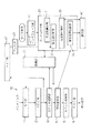
図1は、ディジタル放送受信機の構成図で、図2は、その受信機の動作を説明するフローチャートである。
ディジタル放送受信機は、受信部10、同期部20、コントローラ部30、表示部40から構成される。
【0004】
サーチ開始に際して、コントローラ部30は、周波数算出部31で周波数を算出して(ステップS11)、全周波数のサーチが終了してなければ(ステップS12のN)RF部11に算出した周波数を設定し(ステップS13)、同期部20により同期設定をし(ステップS14)、情報取得記録部34で情報取得を行う。ここで、情報が取得できたか否かの判断を行い(ステップS15)、情報の取得ができていれば(Y)、取得した情報を情報取得記録部34に記録して(ステップS16)、ステップS11へ戻る、情報の取得ができていなければ(N)、直接ステップS11へ戻る。
【0005】
以後、同様の処理を行い、全周波数についてサーチが終了する(ステップS12のY)と、表示部40に情報取得記録部34に記録した全情報を表示して(ステップS17)、サーチを終了する。
受信機のユーザは、表示部40に表示された情報を参照して、希望のプログラムを選択操作する。
【0006】
【発明が解決しようとする課題】
上記従来のディジタル放送受信機においては、設定周波数の全てについてサーチを行っており、放送局がない周波数についても、時間がかかる同期及び情報取得を行っている。このように放送局がない周波数についても時間をかけているため、サーチ開始から終了まで時間がかかっていた。
【0007】
本発明は、全サーチ時間を短縮したディジタル放送受信機を提供することを目的とするものである。
【0008】
【課題を解決するための手段】
本発明は上記目的を達成するためになされたものである。本発明においては、受信部と同期部と制御部と表示部を具備するディジタル放送受信機において、制御部は、受信可能な放送情報のサーチを行うための周波数を算出する周波数算出部と、算出部により算出した周波数に放送波が存在するか否かを判断する放送波判断部と、放送波判断部が放送波が存在すると判断した周波数を記録する周波数記録部と、取得した情報を記録する情報記録部とを有する。
【0009】
この制御部は、周波数算出部で周波数の算出をし、算出した各周波数ごとに受信部にRF設定をし、各周波数ごとに放送波判断部で放送波の有無の判断をし、放送波が存在する周波数を周波数記録部に記録し、その周波数を表示部に表示し、全周波数についての放送波の有無の判断が終了した後に、周波数記録部に記録された各周波数ごとに、受信部にRF設定をし、同期部により同期設定をし、受信部から読み取った放送情報を情報記録部に記録し、周波数を表示した表示部に、取得した情報の内容を追加表示する。
【0011】
本発明は、上記ディジタル放送受信機において、各周波数ごとに放送波判断部で放送波の有無の判断をし、放送波が存在する周波数を周波数記録部に記録したときに、その周波数を表示部に表示し、全周波数についてのサーチが終了した後に、周波数を表示した表示部に、取得した情報の内容を追加表示することができる。これにより、受信可能な周波数の表示が早くなる。
【0012】
さらに、本発明は、放送波判断部は、受信部のディジタル領域におけるFFT(fast Fourier transform)の結果の信号の有無を検知すること、又は、受信部のアナログ領域におけるレベル検知部が検知したレベルによって放送波の存在の有無を判断することができる。
【0013】
【発明の実施の形態】
以下、本発明の実施形態について図を用いて説明する。以下の説明においては、変調にOFDM(orthogonal frequency division multiplex :直交周波数分割多重)を利用するDAB(Digital Audio Broadcasting)に本発明を適用した例ついて説明する。なお、以下の説明に用いる各図においては、同一機能を有する部分には同一の参照符号を付して、重複する説明を省略する。
【0014】
(A方式)
本発明の第1の実施形態(以下、A方式という)について、図3及び図4を用いて説明する。図3は、ディジタル放送受信機の構成図である。
ディジタル放送受信機は、受信部10、同期部20、コントローラ部30、表示部40から構成される。
【0015】
受信部10は、RF部11、A/D変換部12、OFDM復調部13、符号復号部14、MPEG復号部15、D/A変換部16から構成される。アンテナ入力は、RF部11に入力され、音声出力がD/A変換部16より出力される。同期部20は、OFDM復調部13の結果に基づいて、RF部11の同期をとる。この受信部10及び動作部20の構成及び動作は当該技術分野において知られているものであるので、ここでの詳細な説明は省略する。
【0016】
コントローラ部30は、CPU、メモリなどにより構成され、周波数算出部31、周波数記録部32、放送波判断部33、情報取得記録部34を有する。サーチ命令がユーザインターフェース部41を介して入力されると、以下の動作を行って、表示部40にその結果を表示する。
図4は、サーチ時のコントローラ部30の動作を説明するフローチャートである。
【0017】
サーチ開始時に、コントローラ部30は、周波数算出部31で、ディジタル放送をサーチする周波数を算出する(ステップS31)。この周波数の算出が全て終了していなければ(ステップS32のN)、放送波の有無の判断のステップへ進む。
RF部11に算出した周波数を設定し(ステップS33)、放送波判断部33により、この周波数に放送波が存在するか否かを判断する(ステップS34)。この放送波の判断の方式としては種々の手法があり、その具体的方式については後述する。ここで、放送波が存在すると判断した場合(ステップS34のY)は、その周波数を周波数記録部32に記録して(ステップS35)、ステップS31へ戻り、放送波が存在しないと判断した場合は、直接ステップS31へ戻る。
【0018】
ステップS31で次のサーチに用いる周波数を算出し、以後、同様の動作を繰り返し、ディジタル放送の周波数範囲内の全ての周波数について放送波の存在の有無を判断をする。その結果、ディジタル放送の周波数範囲内で放送波が存在する周波数が周波数記録部32に記録される。
ディジタル放送の周波数範囲内の全周波数について放送波の有無の判断が終了する(ステップS32のY)と、次の情報取得及び表示のための段階(ステップS41〜)へ進む。
【0019】
周波数記録部32に記録した周波数の1つが読み出され(ステップS41)、全周波数の読み出しが終了していなければ(S42のN)、RF部11にその周波数を設定し(ステップS43)、同期部20で同期設定をし(ステップS44)、符号復号部14から放送情報を取り出して情報取得記録部34に記録する(ステップS45)。
【0020】
以後は、ステップS41へ戻り、同様の動作を繰り返して、受信可能な放送局に関する放送情報を情報取得記録部34に蓄積していく。そして、周波数記録部32に記録された周波数の読み出しが終了する(ステップS42のY)と、情報取得記録部34に記録してある全情報を表示部40に表示する。
この結果、その地域で受信可能な放送局、放送内容などの放送情報が表示部40に表示される。本実施形態によれば、以下に具体的数値を用いて説明するように、サーチ開始から終了するまでの時間を、従来のものと比較して大幅に短縮することがてきる。
【0021】
今、伝送モードI、全周波数が40個、受信可能周波数が5であり、各処理に要する時間は以下のとおりであるとすると、
A:RF設定に要する時間:10ms(PLL時間)
B:動作設定に要する時間:最低100ms(1フレーム時間)
C:情報取得に要する時間:最低300ms(数フレーム時間)
以上の条件でサーチに要する時間Sは、従来方式と本方式とでは以下のように異なる。
【0022】

【0023】
(B方式)
本発明の第2の実施形態(以下、B方式という)について図5及び図6を用いて説明する。本例が前述のA方式と異なる点は、受信可能な周波数が検知された時に周波数を先に表示し、その他の情報を先に表示した周波数に追加して表示する点である。
【0024】
図5は、ディジタル放送受信機の構成図、図6は、その受信機の動作を説明するフローチャートである。
図5に示した受信機がA方式の図3の受信機と異なる点は、周波数記録部33に記録された周波数が表示部40に表示される点のみであり、その他の点は、図3と同様である。
【0025】
図6のフローチャートについても、A方式の図4と異なる点についてのみ説明をする。
本方式では、放送波の有無の判断のステップ(ステップS31〜35)において、放送波が存在すると判断された周波数を周波数記録部33に記録する(ステップS35)と、それに続いて、その周波数を表示部40に表示をするステップ(ステップS36)が追加される。これにより、同期設定(ステップS44)、情報取得(ステップS45)の前に表示部40に受信可能周波数が表示されるので、周波数表示までの時間が前述のA方式より更に早まる。
【0026】
なお、周波数記録部33へ記録するたびに周波数周波数記録部33に記録する(ステップS36)代わりに、全周波数について放送波の存在の有無の判断が終了した(ステップS32のY)後に、周波数記録部33に記録された全周波数をまとめて表示部40に表示する(ステップS37)こともできる。この場合でも、周波数を早めに表示するという効果を得ることができる。
【0027】
次の情報取得のステップ(ステップS41〜45)は、本B方式では、取得した情報を情報取得記録部34に記録した(ステップS45)後に、その情報を、表示部40に既に表示されている周波数に追加して表示するステップ(ステップS46)が加えられる。また、本B方式の場合は、A方式の図3における全情報の表示(ステップS51)は省略される。
【0028】
また、情報取得記録ごとに追加情報を表示する(ステップS46)代わりに、全周波数について情報取得が終了した(ステップS42のY)後に、情報取得記録部34に記録した全情報をまとめて追加表示する(ステップS47)ようにすることもできる。
次に、以上説明したA方式及びB方式において、コントローラ部30の放送波判断部33による放送波の有無の判断の方式について説明する。
【0029】
(C方式)
放送波の有無の判断を、受信部のディジタル領域において、FFTの結果の信号を見て行う方式をC方式として説明する。
図7は、C方式を採用した受信機の構成を示す。
図7の受信機において、受信機10のA/D変換部12の出力側のディジタル領域に、FFT部42が接続され、FFT部42の結果の信号が放送波判断部32に入力される。ここで、放送波が存在すれば、それはFFT部42の結果の信号にレベルとして現れる。したがって、放送波判断部32は、このレベルによって放送波の存在の有無を判断することができる。
【0030】
なお、図7にはB方式(図5)にC方式を適用した例が示してあるが、本C方式は、A方式(図3)にも適用可能である。また、受信機の動作は、A方式及びB方式の動作(図4、図6)と変わるところはない。
図8〜図11は、C方式において、放送波判断部32がFFT部42の結果の信号のレベルによって放送波の存在の有無を判断する方式について説明する。図8〜図11は、FFTの結果の信号レベルを示し、横軸はFFT周波数、縦軸はFFTレベルを示す。
【0031】
放送波が存在する、即ち、OFDM信号が存在する場合、OFDM信号のキャリアは、1.5MHzの広い帯域に分布し、その帯域外にはキャリアが存在しない。
図8の方式は、OFDM信号の中心周波数のレベルを見て、レベルが所定の基準値以上であれば信号ありと判断する。この方式は、判断のための回路構成を簡易にすることができる。
【0032】
図9の方式は、中心周波数だけでなく、中心付近の複数のレベルを積算し、その積算値が所定の基準値以上であれば信号ありと判断する。この方式は、ノイズにより一点の周波数のレベルが低下しても、他点によりカバーされて確実に信号の検出が可能となる。つまり、レベルを検出する点にノイズが乗ってレベルが低下することがあっても、判断を誤ることがない。
【0033】
図10の方式は、中心付近のみならず、全周波数帯域にわたる複数のレベルを積算し、その積算値が所定の基準値以上であれば信号ありと判断する。この場合、OFDM信号のキャリアが存在しない帯域まで検出範囲を広げ、2MHz程度の範囲についてレベルの検出を行う。この方式によれば、検出範囲が広げられているため、OFDM信号の中心周波数がずれていた場合であっても、確実に信号を検出することが可能となる。
【0034】
図11の方式は、図10の方式と同様に2MHzの周波数範囲にわたりレベルの積算を行うが、キャリアの全て(約2000のFFTポイント)についてレベル検出を行う。そして、その積算値が所定の基準値以上であれば信号ありと判断する。この方式によれば、OFDM信号の中心周波数がずれて、かつ、ノイズにより欠落部分が生じていても、検出が可能である。
【0035】
(D方式)
上記C方式においては、FFTの結果の信号レベルに基づいて放送波の有無を判断している。これに対し、FFTの結果の周波数帯域中の複数のレベルを見て、ヌルキャリアとキャリアの形状に基づいて放送波の有無の判断を行う方式をD方式として説明する。
【0036】
図12の方式は、2MHzの周波数範囲にわたって複数の信号レベルを検出し、このレベルに基づいて、キャリアとヌルキャリアの形状を確認する。ここで、中心付近の複数のポイントで大きいレベルが検出され、端付近のポイントで小さいレベルが認識できれば、OFDMの特徴である幅広いキャリア形状が確認できれたとして、放送波が存在すると判断する。TV放送波などの他のアナログ信号の電波は、キャリアの帯域幅が狭い形状をしているので、本D方式によれば、これらのアナログ放送信号と明確に区別することができ、より正確にOFDM信号の有無を判断できる。
【0037】
図13の方式は、D方式において、周波数帯域の中心付近のレベルと端付近のレベルを検出し、中心付近のレベルから端付近のレベルを引く。この差が所定値以上あれば、形状として中心付近の盛り上がりが認識できるので、OFDM信号が存在すると判断する。
図14の方式は、キャリアとヌルキャリアの境界点を確認することによりOFDM信号の有無を判断するものである。2MHzの周波数範囲にわたって複数の信号レベルを検出し、隣接する信号のレベル差を計算する。そして、レベル差の最大値の点と最小値の点を求める。この点は、図から明らかなように、キャリアとヌルキャリアの境界点である。したがって、レベル差の最大点と最小点の間にキャリアがあるとして、信号の有無を判断することができる。
【0038】
(E方式)
上記D方式において、スレッショルドレベルを設定して、それよりレベルが大の部分をキャリア、それより小の部分をヌルキャリアと認識し、形状が1つの凸型となったときに、OFDM信号が存在すると判断することができる。この方式では、OFDMの特徴である幅広いキャリアを確実に確認できるので、より正確な判断が可能となる。以下、この方式をE方式として説明する。
【0039】
図15の方式は、2MHzの範囲にわたって、複数のポイントのレベルが、スレッショルドレベルより大か小かを見て、大の部分をキャリア、小の部分をヌルキャリアと判定する。そして、信号の形状が1つの凸型となったときに、OFDM信号が存在すると判断する。
このスレッショルドレベルの設定方法は任意であるが、1つの方法として、複数のポイントのレベルを積算してレベル平均を求め、このレベル平均に比例した値に決定することができる。
【0040】
また、信号の形状が1つの凸型と認識できたときに、その凸型の上辺の幅が、OFDMのキャリアの幅(図示の例では1.5MHz)と近似するときに、信号が存在すると判断することができる。これにより、より正確に信号の有無の判断を行える。
図16の方式は、E方式において、信号の形状に凹凸が認められたとき、凹凸の幅が小さいものは無視して信号の形状の判定を行うものである。図16のように、OFDM信号のキャリア部分がノイズにより一部欠落して凹部が発生する場合がある。この凹部の幅が小さいものであれば、それはノイズにより発生したと判断し、この部分を無視して信号形状の判定をする。これにより、ノイズにより誤判断をすることがない。
【0041】
なお、ノイズによる影響が、ヌルキャリア部分に現れた場合、又は凹部でなく凸部で現れた場合も、同様に幅が狭ければ無視をする。また、凹凸の幅が大きい場合は、その凹凸を含んだ形状に基づいて判断を行う。
図17は、ノイズによる影響を回路構成により除去する構成を示すものである。この図17の構成は、前述の図7(C方式)の受信機において、FFT部42の出力側にフィルタを設けたものである。この結果、図18に破線で示すように、OFDM信号の形状は、フィルタリングされることにより、ノイズによる欠落部分が除去される。したがって、ノイズによる影響を排除してより正確な判断が可能となる。
【0042】
なお、図17の回路は、図8〜図16で説明した方式に適用が可能である。
(F方式)
以上説明したC方式は、受信機の構成として、図7又は図17に示したように、受信部のディジタル領域にFFT部42を設けて、FFTの結果を得ている。これに対して、OFDM復調部13のFFT結果データを使用する方式をF方式として以下に説明する。
【0043】
図19は、F方式のディジタル放送受信機の構成を示す。この構成は、図7の受信機の構成とほぼ同様であるので、図7と異なる点についてのみここで説明する。
本F方式においては、OFDM復調部13からFFTデータ44を取り出し、放送波判断部32に入力する。OFDM復調部13を構成するICは、FFT部を含んでいる。また、本方式による周波数のサーチ時には、このICは使用しない。したがって、本F方式によれば、図7又は図17の受信機のように、追加のFFT部42を構成するICが不要となるので、コスト低減を図ることができる。
【0044】
なお、このF方式は、図17の受信機にも適用可能である。また前述のC方式と同様の動作を行うので、図8〜図18の判断方式を適用することが可能である。
図20は、上記F方式において、伝送モードに関係なくサーチを行うことができる受信機の構成を示す。コントローラ部30にモード制御部35が設けられ、これがOFDM復調部13を、最少キャリア数の伝送モードに設定する。
【0045】
OFDMにおいては、伝送モードが、モードI、モードII、モードIII の3種類用意されている。そして、各モードに応じてキャリア数(FFTポイント数)が変更される。本F方式では、サーチ時のFFTのポイント数を、各モードの内、最もFFTポイント数が少ないモードIII の数に設定する。既に説明してきたOFDM信号の有無の判定には、FFTポイント数は少なくても可能であり、本F方式で良好な判断をすることができる。また、FFTポイント数を少なくできるので、判断時間も短縮される。
【0046】
(G方式)
以上説明してきたC方式〜F方式は、放送波の有無の判断を受信機のディジタル領域において行っている。これに対し、受信機のアナログ領域において放送波の有無の判断を行う方式をG方式として説明する。
図21は、G方式の受信機の構成を示す。図21は、図5のB方式にG方式を適用した例が示してあるが、本G方式は、A方式(図3)にも適用可能である。
【0047】
図21の説明においても、図5と異なる点についてのみ説明をする。受信機10のRF設定部11の出力側のアナログ領域に、レベル検知部45が接続され、レベル検知部45の結果が放送波判断部32に入力される。ここで、サーチ周波数に放送波が存在すれば、レベル検知部45の出力信号レベルとして現れる。したがって、放送波判断部33は、このレベルにより放送波の存在の有無を判断することができる。
【0048】
また、アナログ領域において判断を行うことにより、より早い放送波の有無の判断が可能となる。なお、受信機の動作は、A方式及びB方式の動作と変わるところはない。
図22は、G方式の受信機の変形例を示す。
図22の受信機は、レベル検知部45の前段に帯域分割部46を挿入する。この帯域分割部46は、OFDM信号のある帯域とない帯域とに分割し、レベル検知部45はそれぞれの帯域においてレベル検知を行う。そして、OFDM信号のある帯域においてレベルが検出される条件と、ない帯域においてレベルが検出されないという条件が両立したときに、放送波が存在すると判断をする。
【0049】
以上説明したC〜G方式においては、OFDM復調を使用する例について説明をしてきたが、DAB信号波は、図23に示すように、フレーム信号の間に信号がないヌル時間が存在する。このヌル時間のときに信号を検出して放送波の有無の判断をすると、信号が検出されないために、受信可能な信号が存在するのに存在しないと誤って判断することがある。
【0050】
この誤判断を防止するため、DABのようにヌル時間を有する方式の場合には、ヌル時間を超えた間隔で、連続して信号の検出を行い、放送波の有無の判断を行う。これにより、仮に第1回の信号検出がヌル時間に当たったとしても、次の第2回の信号検出は、確実に信号が検出できるタイミングとなるので、より確実にDABのOFDM信号の検出が可能となる。
【図面の簡単な説明】
【図1】従来のディジタル放送受信機の構成図。
【図2】図1の受信機の動作を説明するフローチャート。
【図3】本発明のA方式のディジタル放送受信機の構成を示す図。
【図4】図3の受信機の動作を説明するためのフローチャート。
【図5】本発明のB方式のディジタル放送受信機の構成を示す図。
【図6】図5の受信機の動作を説明するためのフローチャート。
【図7】本発明のC方式のディジタル放送受信機の構成を示す図。
【図8】C方式による放送波の有無の判断方式を説明する図(その1)。
【図9】C方式による放送波の有無の判断方式を説明する図(その2)。
【図10】C方式による放送波の有無の判断方式を説明する図(その3)。
【図11】C方式による放送波の有無の判断方式を説明する図(その4)。
【図12】本発明のD方式による放送波の有無の判断方式を説明する図(その1)。
【図13】本発明のD方式による放送波の有無の判断方式を説明する図(その2)。
【図14】本発明のD方式による放送波の有無の判断方式を説明する図(その3)。
【図15】本発明のE方式による放送波の有無の判断方式を説明する図(その1)。
【図16】本発明のE方式による放送波の有無の判断方式を説明する図(その2)。
【図17】図7のC方式のディジタル放送受信機の変形例を示す図。
【図18】図17の受信機における放送波の有無の判断方式を説明する図。
【図19】本発明のF方式のディジタル放送受信機の構成を示す図。
【図20】F方式の受信機の変形例を示す図。
【図21】本発明のG方式のディジタル放送受信機の構成を示す図。
【図22】G方式の受信機の変形例を示す図。
【図23】C方式〜G方式において判断をヌル時間を超えて行う理由を説明する図。
【符号の説明】
10…受信部
11…RF部
12…A/D変換部
13…OFDM復調部
14…符号復号部
15…MPEG復号部
16…D/A変換部
20…同期部
30…コントローラ部
31…周波数算出部
32…周波数記録部
33…放送波記録部
34…情報取得記録部
35…モード制御部
40…表示部
41…ユーザインターフェース部
42…FFT部
43…フィルタ
44…FFTデータ
45…レベル検知部
46…帯域分割部[0001]
BACKGROUND OF THE INVENTION
The present invention relates to a digital broadcast receiver.
[0002]
[Prior art]
In digital broadcast receivers used for digital broadcasting (eg, DAB), search for broadcast information such as broadcast stations that can be received in the area where the receiver is located, broadcast contents, etc., and display broadcast information about the broadcast stations that can be received. To display. The user sees this display and selects a desired broadcast station.
[0003]
A conventional search method will be described with reference to the drawings.
FIG. 1 is a block diagram of a digital broadcast receiver, and FIG. 2 is a flowchart for explaining the operation of the receiver.
The digital broadcast receiver includes a
[0004]
At the start of the search, the
[0005]
Thereafter, the same processing is performed, and when the search is completed for all frequencies (Y in step S12), all information recorded in the information
The user of the receiver refers to the information displayed on the
[0006]
[Problems to be solved by the invention]
In the conventional digital broadcast receiver, a search is performed for all the set frequencies, and time-consuming synchronization and information acquisition are performed even for frequencies where there is no broadcast station. As described above, since it takes time for a frequency where there is no broadcasting station, it takes time from the start to the end of the search.
[0007]
An object of the present invention is to provide a digital broadcast receiver with a reduced total search time.
[0008]
[Means for Solving the Problems]
The present invention has been made to achieve the above object. In the present invention, in a digital broadcast receiver including a receiving unit, a synchronizing unit, a control unit, and a display unit, the control unit calculates a frequency for searching for receivable broadcast information; A broadcast wave determination unit that determines whether or not a broadcast wave exists at the frequency calculated by the unit, a frequency recording unit that records a frequency that the broadcast wave determination unit determines that a broadcast wave exists, and records the acquired information And an information recording unit.
[0009]
The control unit calculates the frequency by the frequency calculation unit, sets the RF setting in the reception unit for each calculated frequency, determines the presence / absence of the broadcast wave by the broadcast wave determination unit for each frequency, The existing frequency is recorded in the frequency recording unit, the frequency is displayed on the display unit, and after the determination of the presence or absence of the broadcast wave for all frequencies is completed, for each frequency recorded in the frequency recording unit , the receiving unit RF setting is performed, synchronization setting is performed by the synchronization unit, broadcast information read from the reception unit is recorded in the information recording unit, and the content of the acquired information is additionally displayed on the display unit displaying the frequency .
[0011]
In the digital broadcast receiver, the broadcast wave determination unit determines the presence or absence of a broadcast wave for each frequency, and when the frequency at which the broadcast wave exists is recorded in the frequency recording unit, the frequency is displayed on the display unit. After the search for all frequencies is completed, the contents of the acquired information can be additionally displayed on the display unit displaying the frequencies. As a result, the display of the receivable frequency is fast Kunar.
[0012]
Further, in the present invention, the broadcast wave determining unit detects the presence or absence of a signal resulting from FFT (fast Fourier transform) in the digital domain of the receiver, or the level detected by the level detector in the analog domain of the receiver The presence / absence of a broadcast wave can be determined by.
[0013]
DETAILED DESCRIPTION OF THE INVENTION
Hereinafter, embodiments of the present invention will be described with reference to the drawings. In the following description, an example in which the present invention is applied to DAB (Digital Audio Broadcasting) using OFDM (orthogonal frequency division multiplex) for modulation will be described. In the drawings used for the following description, parts having the same function are denoted by the same reference numerals, and redundant description is omitted.
[0014]
(A method)
A first embodiment of the present invention (hereinafter referred to as A method) will be described with reference to FIGS. FIG. 3 is a block diagram of a digital broadcast receiver.
The digital broadcast receiver includes a
[0015]
The
[0016]
The
FIG. 4 is a flowchart for explaining the operation of the
[0017]
At the start of the search, the
The calculated frequency is set in the RF unit 11 (step S33), and the broadcast
[0018]
In step S31, the frequency used for the next search is calculated, and thereafter the same operation is repeated to determine whether or not there is a broadcast wave for all frequencies in the digital broadcast frequency range. As a result, the frequency where the broadcast wave exists within the frequency range of digital broadcasting is recorded in the
When the determination of the presence / absence of broadcast waves is completed for all frequencies within the frequency range of digital broadcasting (Y in step S32), the process proceeds to the next stage for obtaining and displaying information (steps S41 to S41).
[0019]
If one of the frequencies recorded in the
[0020]
Thereafter, the process returns to step S41, and the same operation is repeated to accumulate broadcast information relating to receivable broadcast stations in the information
As a result, broadcast information such as broadcast stations and broadcast contents that can be received in the area is displayed on the
[0021]
Now, assuming that the transmission mode I, the total frequency is 40, the receivable frequency is 5, and the time required for each processing is as follows:
A: Time required for RF setting: 10 ms (PLL time)
B: Time required for operation setting: at least 100 ms (one frame time)
C: Time required for information acquisition: at least 300 ms (several frame time)
The time S required for the search under the above conditions differs between the conventional method and the present method as follows.
[0022]
[0023]
(B method)
A second embodiment of the present invention (hereinafter referred to as “B system”) will be described with reference to FIGS. This example is different from the A method described above in that when a receivable frequency is detected, the frequency is displayed first, and other information is displayed in addition to the previously displayed frequency.
[0024]
FIG. 5 is a block diagram of the digital broadcast receiver, and FIG. 6 is a flowchart for explaining the operation of the receiver.
The only difference between the receiver shown in FIG. 5 and the A-system receiver shown in FIG. 3 is that the frequency recorded in the
[0025]
Only the points of the flowchart of FIG. 6 that are different from the A method of FIG. 4 will be described.
In this method, in the step of determining whether or not there is a broadcast wave (steps S31 to S35), the frequency determined that the broadcast wave is present is recorded in the frequency recording unit 33 (step S35). A step of displaying on the display unit 40 (step S36) is added. Thereby, since the receivable frequency is displayed on the
[0026]
Instead of recording in the
[0027]
In the next information acquisition step (steps S41 to S45), in the present B method, after the acquired information is recorded in the information acquisition recording unit 34 (step S45), the information is already displayed on the
[0028]
Further, instead of displaying additional information for each information acquisition record (step S46), after information acquisition is completed for all frequencies (Y in step S42), all information recorded in the information
Next, in the A method and the B method described above, a method for determining the presence / absence of a broadcast wave by the broadcast
[0029]
(C method)
A method in which the presence / absence of a broadcast wave is determined by looking at the signal resulting from the FFT in the digital domain of the receiver will be described as a C method.
FIG. 7 shows a configuration of a receiver employing the C method.
In the receiver of FIG. 7, the
[0030]
Although FIG. 7 shows an example in which the C method is applied to the B method (FIG. 5), the C method can also be applied to the A method (FIG. 3). The operation of the receiver is not different from the operation of the A method and the B method (FIGS. 4 and 6).
FIGS. 8-11 demonstrates the system in which the broadcast
[0031]
When a broadcast wave exists, that is, when an OFDM signal exists, the OFDM signal carriers are distributed over a wide band of 1.5 MHz, and no carriers exist outside the band.
In the method of FIG. 8, the level of the center frequency of the OFDM signal is seen, and if the level is equal to or higher than a predetermined reference value, it is determined that there is a signal. This method can simplify the circuit configuration for determination.
[0032]
In the method of FIG. 9, not only the center frequency but also a plurality of levels near the center are integrated, and if the integrated value is equal to or greater than a predetermined reference value, it is determined that there is a signal. In this method, even if the frequency level at one point is lowered due to noise, the signal is reliably detected by being covered by another point. That is, even when noise is added to the point where the level is detected and the level is lowered, the determination is not made erroneously.
[0033]
The method of FIG. 10 integrates a plurality of levels not only near the center but also over the entire frequency band, and determines that there is a signal if the integrated value is equal to or greater than a predetermined reference value. In this case, the detection range is extended to a band where no OFDM signal carrier exists, and level detection is performed for a range of about 2 MHz. According to this method, since the detection range is widened, it is possible to reliably detect the signal even when the center frequency of the OFDM signal is shifted.
[0034]
The method of FIG. 11 performs level integration over a frequency range of 2 MHz as in the method of FIG. 10, but performs level detection for all carriers (about 2000 FFT points). If the integrated value is equal to or greater than a predetermined reference value, it is determined that there is a signal. According to this method, detection is possible even when the center frequency of the OFDM signal is shifted and a missing portion is generated due to noise.
[0035]
(D method)
In the C method, the presence / absence of a broadcast wave is determined based on the signal level of the FFT result. On the other hand, a method of judging the presence or absence of a broadcast wave based on the null carrier and the shape of the carrier by looking at a plurality of levels in the frequency band as a result of the FFT will be described as a D method.
[0036]
The system of FIG. 12 detects a plurality of signal levels over a frequency range of 2 MHz, and confirms the shapes of the carrier and the null carrier based on these levels. Here, if a large level is detected at a plurality of points near the center and a small level can be recognized at a point near the end, it is determined that a broadcast wave exists, assuming that a wide carrier shape that is characteristic of OFDM has been confirmed. Since other analog signals such as TV broadcast waves have a narrow carrier bandwidth, this D method can be clearly distinguished from these analog broadcast signals and more accurately. The presence or absence of an OFDM signal can be determined.
[0037]
The method shown in FIG. 13 detects the level near the center and the level near the end of the frequency band in the D method, and subtracts the level near the end from the level near the center. If this difference is greater than or equal to a predetermined value, a bulge near the center can be recognized as a shape, and it is determined that an OFDM signal exists.
The method of FIG. 14 determines the presence or absence of an OFDM signal by confirming the boundary point between a carrier and a null carrier. A plurality of signal levels are detected over a frequency range of 2 MHz, and a level difference between adjacent signals is calculated. Then, the maximum value point and the minimum value point of the level difference are obtained. This point is a boundary point between the carrier and the null carrier, as is apparent from the figure. Therefore, the presence or absence of a signal can be determined by assuming that there is a carrier between the maximum point and the minimum point of the level difference.
[0038]
(E method)
In the above-mentioned D method, when a threshold level is set, a portion whose level is higher than that is recognized as a carrier, a portion lower than that is recognized as a null carrier, and an OFDM signal exists when the shape becomes one convex shape. It can be determined. In this method, since a wide range of carriers, which is a feature of OFDM, can be confirmed with certainty, more accurate determination is possible. Hereinafter, this method will be described as an E method.
[0039]
The method of FIG. 15 determines whether the level of a plurality of points is larger or smaller than the threshold level over the range of 2 MHz, and determines that the most part is a carrier and the small part is a null carrier. Then, when the shape of the signal becomes one convex shape, it is determined that the OFDM signal exists.
Although the threshold level setting method is arbitrary, as one method, the level average is obtained by integrating the levels of a plurality of points, and a value proportional to the level average can be determined.
[0040]
Also, when the signal shape can be recognized as one convex shape, the signal exists when the width of the upper side of the convex shape approximates the width of the OFDM carrier (1.5 MHz in the illustrated example). Judgment can be made. Thereby, the presence or absence of a signal can be determined more accurately.
In the method of FIG. 16, in the case of the E method, when irregularities are recognized in the signal shape, the signal shape is determined by ignoring the small irregularity width. As shown in FIG. 16, the carrier portion of the OFDM signal may be partially lost due to noise to generate a recess. If the width of the concave portion is small, it is determined that it is caused by noise, and the signal shape is determined ignoring this portion. As a result, no erroneous determination is made due to noise.
[0041]
In addition, when the influence by noise appears in the null carrier part, or when it appears in the convex part instead of the concave part, it is ignored if the width is similarly narrow. Further, when the width of the unevenness is large, the determination is made based on the shape including the unevenness.
FIG. 17 shows a configuration in which the influence of noise is removed by a circuit configuration. The configuration shown in FIG. 17 is obtained by providing a filter on the output side of the
[0042]
Note that the circuit of FIG. 17 can be applied to the method described with reference to FIGS.
(F method)
In the C method described above, as shown in FIG. 7 or FIG. 17, the
[0043]
FIG. 19 shows the configuration of an F-type digital broadcast receiver. Since this configuration is almost the same as the configuration of the receiver of FIG. 7, only differences from FIG. 7 will be described here.
In this F system, the
[0044]
This F method can also be applied to the receiver of FIG. Further, since the same operation as the above-described C method is performed, the determination methods of FIGS. 8 to 18 can be applied.
FIG. 20 shows a configuration of a receiver that can perform a search regardless of the transmission mode in the F method. The
[0045]
In OFDM, three types of transmission modes, Mode I, Mode II, and Mode III, are prepared. Then, the number of carriers (number of FFT points) is changed according to each mode. In this F method, the number of FFT points at the time of search is set to the number of mode III with the smallest number of FFT points among the modes. The determination of the presence / absence of the OFDM signal already described can be performed even if the number of FFT points is small, and a good determination can be made by the present F method. In addition, since the number of FFT points can be reduced, the determination time is also shortened.
[0046]
(G method)
In the C method to F method described above, the presence / absence of a broadcast wave is determined in the digital domain of the receiver. On the other hand, a method for determining the presence or absence of broadcast waves in the analog domain of the receiver will be described as a G method.
FIG. 21 shows a configuration of a G-type receiver. FIG. 21 shows an example in which the G method is applied to the B method of FIG. 5, but the present G method can also be applied to the A method (FIG. 3).
[0047]
Also in the description of FIG. 21, only differences from FIG. 5 will be described. The
[0048]
In addition, by making a determination in the analog domain, it is possible to determine the presence or absence of a broadcast wave earlier. The operation of the receiver is not different from the operation of the A method and the B method.
FIG. 22 shows a modification of the G-type receiver.
The receiver shown in FIG. 22 inserts a
[0049]
In the CG method described above, an example in which OFDM demodulation is used has been described, but a DAB signal wave has a null time in which there is no signal between frame signals, as shown in FIG. If a signal is detected during the null time to determine the presence or absence of a broadcast wave, the signal may not be detected, so that it may be erroneously determined that a receivable signal exists but does not exist.
[0050]
In order to prevent this erroneous determination, in the case of a system having a null time, such as DAB, signals are continuously detected at intervals exceeding the null time, and the presence / absence of a broadcast wave is determined. As a result, even if the first signal detection hits the null time, the next second signal detection is a timing at which the signal can be detected reliably, so that the detection of the OFDM signal of the DAB can be performed more reliably. It becomes possible.
[Brief description of the drawings]
FIG. 1 is a configuration diagram of a conventional digital broadcast receiver.
FIG. 2 is a flowchart for explaining the operation of the receiver of FIG. 1;
FIG. 3 is a diagram showing a configuration of an A-system digital broadcast receiver according to the present invention.
4 is a flowchart for explaining the operation of the receiver of FIG. 3;
FIG. 5 is a diagram showing a configuration of a B-system digital broadcast receiver according to the present invention.
6 is a flowchart for explaining the operation of the receiver in FIG. 5;
FIG. 7 is a diagram showing a configuration of a C-system digital broadcast receiver according to the present invention.
FIG. 8 is a diagram for explaining a method of determining the presence / absence of a broadcast wave by the C method (part 1);
FIG. 9 is a diagram for explaining a determination method of presence / absence of a broadcast wave by the C method (part 2);
FIG. 10 is a diagram for explaining a determination method of presence / absence of a broadcast wave by the C method (part 3);
FIG. 11 is a diagram for explaining a determination method of presence / absence of a broadcast wave by the C method (part 4);
FIG. 12 is a diagram for explaining a method for determining the presence / absence of a broadcast wave according to the D method of the present invention (part 1);
FIG. 13 is a diagram (No. 2) for explaining the determination method of the presence / absence of a broadcast wave according to the D method of the present invention;
FIG. 14 is a diagram for explaining a method for determining the presence / absence of a broadcast wave according to the D method of the present invention (part 3);
FIG. 15 is a diagram for explaining a method for determining the presence / absence of a broadcast wave according to the E method of the present invention (part 1);
FIG. 16 is a diagram (part 2) for explaining a determination method of presence / absence of a broadcast wave by the E method of the present invention;
17 is a diagram showing a modification of the C-system digital broadcast receiver of FIG. 7;
18 is a diagram for explaining a method for determining the presence or absence of a broadcast wave in the receiver of FIG. 17;
FIG. 19 is a diagram showing a configuration of an F-system digital broadcast receiver according to the present invention.
FIG. 20 is a diagram illustrating a modified example of an F-system receiver.
FIG. 21 is a diagram showing a configuration of a G-type digital broadcast receiver according to the present invention;
FIG. 22 is a diagram illustrating a modified example of a G-type receiver.
FIG. 23 is a diagram for explaining the reason for making a determination beyond the null time in the C method to the G method.
[Explanation of symbols]
DESCRIPTION OF
Claims (19)
前記制御部は、
受信可能な放送情報のサーチを行うための周波数を算出する周波数算出部と、
前記算出部により算出した周波数に放送波が存在するか否かを判断する放送波判断部と、
前記放送波判断部が放送波が存在すると判断した周波数を記録する周波数記録部と、
取得した情報を記録する情報記録部とを有し、
前記制御部は、前記周波数算出部で前記周波数の算出をし、算出した各周波数ごとに前記受信部にRF設定をし、各周波数ごとに前記放送波判断部で放送波の有無の判断をし、放送波が存在する周波数を前記周波数記録部に記録し、その周波数を前記表示部に表示し、全周波数についての放送波の有無の判断が終了した後に、前記周波数記録部に記録された各周波数ごとに前記受信部にRF設定をし、前記同期部により同期設定をし、前記受信部から読み取った放送情報を前記情報記録部に記録し、前記周波数を表示した表示部に、前記取得した情報の内容を追加表示することを特徴とするディジタル放送受信機。In a digital broadcast receiver comprising a receiving unit, a synchronizing unit, a control unit, and a display unit,
The controller is
A frequency calculation unit that calculates a frequency for searching for receivable broadcast information;
A broadcast wave determination unit that determines whether a broadcast wave exists at the frequency calculated by the calculation unit;
A frequency recording unit that records a frequency at which the broadcast wave determination unit determines that a broadcast wave exists;
An information recording unit for recording the acquired information;
The control unit calculates the frequency by the frequency calculation unit, sets RF to the reception unit for each calculated frequency, and determines whether or not there is a broadcast wave by the broadcast wave determination unit for each frequency. , The frequency at which the broadcast wave exists is recorded in the frequency recording unit, the frequency is displayed on the display unit, and after the determination of the presence / absence of the broadcast wave for all frequencies is completed, each frequency recorded in the frequency recording unit RF setting is performed on the receiving unit for each frequency, synchronization setting is performed by the synchronizing unit, broadcast information read from the receiving unit is recorded in the information recording unit, and the obtained information is displayed on the display unit displaying the frequency. A digital broadcast receiver characterized by additionally displaying information contents.
Priority Applications (2)
| Application Number | Priority Date | Filing Date | Title |
|---|---|---|---|
| JP03741398A JP3955143B2 (en) | 1998-02-19 | 1998-02-19 | Digital broadcast receiver |
| EP99300584A EP0938199A3 (en) | 1998-02-19 | 1999-01-27 | Means for determining available reception frequencies in a receiver for the reception of digital broadcasts |
Applications Claiming Priority (1)
| Application Number | Priority Date | Filing Date | Title |
|---|---|---|---|
| JP03741398A JP3955143B2 (en) | 1998-02-19 | 1998-02-19 | Digital broadcast receiver |
Related Child Applications (1)
| Application Number | Title | Priority Date | Filing Date |
|---|---|---|---|
| JP2007025206A Division JP2007174696A (en) | 2007-02-05 | 2007-02-05 | Digital broadcast receiver |
Publications (2)
| Publication Number | Publication Date |
|---|---|
| JPH11234092A JPH11234092A (en) | 1999-08-27 |
| JP3955143B2 true JP3955143B2 (en) | 2007-08-08 |
Family
ID=12496847
Family Applications (1)
| Application Number | Title | Priority Date | Filing Date |
|---|---|---|---|
| JP03741398A Expired - Fee Related JP3955143B2 (en) | 1998-02-19 | 1998-02-19 | Digital broadcast receiver |
Country Status (2)
| Country | Link |
|---|---|
| EP (1) | EP0938199A3 (en) |
| JP (1) | JP3955143B2 (en) |
Families Citing this family (11)
| Publication number | Priority date | Publication date | Assignee | Title |
|---|---|---|---|---|
| DE10005287A1 (en) * | 2000-02-07 | 2001-08-09 | Rohde & Schwarz | Method for determining the residual carrier power in a multi-carrier signal QAM-modulated in 8K mode according to the DVB-T standard |
| EP1139591A3 (en) * | 2000-03-28 | 2004-07-14 | CLARION Co., Ltd. | Method and receiver for receiving Digital Audio Broadcast (DAB) |
| US7383567B2 (en) | 2001-07-27 | 2008-06-03 | Thomson Licensing | Method and system for creating a subset of programming channels |
| JP4842506B2 (en) * | 2003-09-12 | 2011-12-21 | マスプロ電工株式会社 | Signal level measuring device |
| JP2008016993A (en) * | 2006-07-04 | 2008-01-24 | Clarion Co Ltd | Television broadcasting receiver and broadcasting frequency information acquiring method |
| CN101682347B (en) * | 2007-05-30 | 2012-11-21 | 三菱电机株式会社 | Digital broadcast receiver |
| JP4985359B2 (en) * | 2007-11-30 | 2012-07-25 | 株式会社Jvcケンウッド | Wireless receiver |
| JP4554698B2 (en) * | 2008-09-01 | 2010-09-29 | 株式会社Kddi研究所 | OFDM signal demodulator |
| WO2011024227A1 (en) | 2009-08-28 | 2011-03-03 | 三菱電機株式会社 | Radio receiver |
| JP5662922B2 (en) * | 2011-11-25 | 2015-02-04 | 日本電信電話株式会社 | Signal processing apparatus and signal processing method |
| JP5433803B2 (en) * | 2013-03-08 | 2014-03-05 | パナソニック オートモーティブ システムズ カンパニー オブ アメリカ ディビジョン オブ パナソニック コーポレイション オブ ノース アメリカ | Method and apparatus for dynamically adapting FM tuner sensitivity to a local environment for a single tuner system |
Family Cites Families (2)
| Publication number | Priority date | Publication date | Assignee | Title |
|---|---|---|---|---|
| AU8009594A (en) * | 1994-08-04 | 1996-03-04 | Harry Edwin Emerson | Radio scanner and display system |
| EP0786889B1 (en) * | 1996-02-02 | 2002-04-17 | Deutsche Thomson-Brandt Gmbh | Method for the reception of multicarrier signals and related apparatus |
-
1998
- 1998-02-19 JP JP03741398A patent/JP3955143B2/en not_active Expired - Fee Related
-
1999
- 1999-01-27 EP EP99300584A patent/EP0938199A3/en not_active Withdrawn
Also Published As
| Publication number | Publication date |
|---|---|
| JPH11234092A (en) | 1999-08-27 |
| EP0938199A2 (en) | 1999-08-25 |
| EP0938199A3 (en) | 2000-08-09 |
Similar Documents
| Publication | Publication Date | Title |
|---|---|---|
| JP3955143B2 (en) | Digital broadcast receiver | |
| US8055186B2 (en) | Satellite transmission channel detection method and reception device using the method | |
| US4594611A (en) | Station selecting method for television receiver | |
| EP0940939B1 (en) | Digital audio broadcast receiver comprising a system for quickly acquiring frame synchronization in the presence of noise | |
| EP1139564A2 (en) | Broadcast receiver comprising a means for scanning alternative frequencies without deteriorating the reception of a currently received broadcast programme | |
| JP4510236B2 (en) | Radio signal transmission method using orthogonal frequency division multiplexing and receiver for receiving radio signal using orthogonal frequency division multiplexing | |
| CA2244382C (en) | Apparatus for receiving digital information signals | |
| EP1100237A3 (en) | Methods and apparatus for frame synchronization in a digital audio broadcasting system | |
| US6542563B1 (en) | Reception method and receiver for digital radio communication system | |
| JP2006352488A (en) | Digital broadcast receiver, method and program for judging broadcasting system | |
| US7308235B2 (en) | Audio broadcast receiver and automatic broadcasting-station selecting method | |
| JP2008504726A (en) | FFT carrier frequency offset estimation for OFDM signal | |
| JP2008504726A5 (en) | ||
| JP2007174696A (en) | Digital broadcast receiver | |
| JP3798604B2 (en) | Broadcast system discrimination device and broadcast system discrimination method | |
| EP1041757A3 (en) | Receiver for receiving broadcasting signals comprising two tuners, at least one of which is a receiver for receiving a Digital Audio Broadcast signal, comprising a means for comparing the output signals of the two receivers as well as a means for selecting either of those signals | |
| JP2001203596A (en) | Receiver for radio broadcast program transmitted by analog and digital signals | |
| EP1162836A2 (en) | Television receiver for receiving both analog and digital broadcast programmes | |
| JP3363764B2 (en) | OFDM broadcast receiver | |
| EP0599330B1 (en) | RDS receiver | |
| KR100262649B1 (en) | Method and device of searching channel of digital tv | |
| JP2000059706A (en) | Channel selection system for television receiver | |
| JP2000307965A (en) | Television receiver | |
| EP1037440A2 (en) | Null symbol detecting device | |
| JP2000151551A (en) | Receiver |
Legal Events
| Date | Code | Title | Description |
|---|---|---|---|
| A621 | Written request for application examination |
Free format text: JAPANESE INTERMEDIATE CODE: A621 Effective date: 20041117 |
|
| A977 | Report on retrieval |
Free format text: JAPANESE INTERMEDIATE CODE: A971007 Effective date: 20061130 |
|
| A131 | Notification of reasons for refusal |
Free format text: JAPANESE INTERMEDIATE CODE: A131 Effective date: 20061205 |
|
| A521 | Written amendment |
Free format text: JAPANESE INTERMEDIATE CODE: A523 Effective date: 20070205 |
|
| TRDD | Decision of grant or rejection written | ||
| A01 | Written decision to grant a patent or to grant a registration (utility model) |
Free format text: JAPANESE INTERMEDIATE CODE: A01 Effective date: 20070403 |
|
| A61 | First payment of annual fees (during grant procedure) |
Free format text: JAPANESE INTERMEDIATE CODE: A61 Effective date: 20070501 |
|
| R150 | Certificate of patent or registration of utility model |
Free format text: JAPANESE INTERMEDIATE CODE: R150 |
|
| FPAY | Renewal fee payment (event date is renewal date of database) |
Free format text: PAYMENT UNTIL: 20110511 Year of fee payment: 4 |
|
| FPAY | Renewal fee payment (event date is renewal date of database) |
Free format text: PAYMENT UNTIL: 20110511 Year of fee payment: 4 |
|
| FPAY | Renewal fee payment (event date is renewal date of database) |
Free format text: PAYMENT UNTIL: 20120511 Year of fee payment: 5 |
|
| FPAY | Renewal fee payment (event date is renewal date of database) |
Free format text: PAYMENT UNTIL: 20120511 Year of fee payment: 5 |
|
| FPAY | Renewal fee payment (event date is renewal date of database) |
Free format text: PAYMENT UNTIL: 20130511 Year of fee payment: 6 |
|
| FPAY | Renewal fee payment (event date is renewal date of database) |
Free format text: PAYMENT UNTIL: 20130511 Year of fee payment: 6 |
|
| FPAY | Renewal fee payment (event date is renewal date of database) |
Free format text: PAYMENT UNTIL: 20140511 Year of fee payment: 7 |
|
| LAPS | Cancellation because of no payment of annual fees |