EP1139546A1 - Automotive alternator - Google Patents
Automotive alternator Download PDFInfo
- Publication number
- EP1139546A1 EP1139546A1 EP01101690A EP01101690A EP1139546A1 EP 1139546 A1 EP1139546 A1 EP 1139546A1 EP 01101690 A EP01101690 A EP 01101690A EP 01101690 A EP01101690 A EP 01101690A EP 1139546 A1 EP1139546 A1 EP 1139546A1
- Authority
- EP
- European Patent Office
- Prior art keywords
- coil
- stator
- fan
- rotor
- portions
- Prior art date
- Legal status (The legal status is an assumption and is not a legal conclusion. Google has not performed a legal analysis and makes no representation as to the accuracy of the status listed.)
- Granted
Links
Images





Classifications
-
- H—ELECTRICITY
- H02—GENERATION; CONVERSION OR DISTRIBUTION OF ELECTRIC POWER
- H02K—DYNAMO-ELECTRIC MACHINES
- H02K9/00—Arrangements for cooling or ventilating
- H02K9/02—Arrangements for cooling or ventilating by ambient air flowing through the machine
- H02K9/04—Arrangements for cooling or ventilating by ambient air flowing through the machine having means for generating a flow of cooling medium
-
- H—ELECTRICITY
- H02—GENERATION; CONVERSION OR DISTRIBUTION OF ELECTRIC POWER
- H02K—DYNAMO-ELECTRIC MACHINES
- H02K9/00—Arrangements for cooling or ventilating
- H02K9/02—Arrangements for cooling or ventilating by ambient air flowing through the machine
- H02K9/04—Arrangements for cooling or ventilating by ambient air flowing through the machine having means for generating a flow of cooling medium
- H02K9/06—Arrangements for cooling or ventilating by ambient air flowing through the machine having means for generating a flow of cooling medium with fans or impellers driven by the machine shaft
-
- H—ELECTRICITY
- H02—GENERATION; CONVERSION OR DISTRIBUTION OF ELECTRIC POWER
- H02K—DYNAMO-ELECTRIC MACHINES
- H02K1/00—Details of the magnetic circuit
- H02K1/06—Details of the magnetic circuit characterised by the shape, form or construction
- H02K1/22—Rotating parts of the magnetic circuit
- H02K1/32—Rotating parts of the magnetic circuit with channels or ducts for flow of cooling medium
- H02K1/325—Rotating parts of the magnetic circuit with channels or ducts for flow of cooling medium between salient poles
-
- H—ELECTRICITY
- H02—GENERATION; CONVERSION OR DISTRIBUTION OF ELECTRIC POWER
- H02K—DYNAMO-ELECTRIC MACHINES
- H02K5/00—Casings; Enclosures; Supports
- H02K5/04—Casings or enclosures characterised by the shape, form or construction thereof
- H02K5/22—Auxiliary parts of casings not covered by groups H02K5/06-H02K5/20, e.g. shaped to form connection boxes or terminal boxes
Definitions
- the present invention relates to an automotive alternator provided with a blowing means.
- Figure 25 is a cross section of a conventional automotive alternator
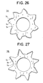
- Figures 26 and 27 are front elevations showing a front-end fan and a rear-end fan, respectively, used in a rotor of the conventional automotive alternator.
- This automotive alternator is constructed by rotatably mounting a Lundell-type rotor 7 by means of a shaft 6 inside a case 3 constructed from an aluminum front bracket 1 and an aluminum rear bracket 2, and fastening a stator 8 to an inner wall of the case 3 so as to cover an outer circumferential side of the rotor 7.
- the shaft 6 is rotatably supported in the front bracket 1 and the rear bracket 2.
- a pulley 4 is fastened to a first end of this shaft 6 such that rotational torque from an engine can be transmitted to the shaft 6 by means of a belt (not shown).
- Slip rings 9 for supplying electric current to the rotor 7 are fastened to a second end of the shaft 6, and a pair of brushes 10 are housed in a brush holder 11 disposed inside the case 3 such that the pair of brushes 10 slide in contact with the slip rings 9.
- a regulator 18 for adjusting the magnitude of alternating voltage generated in the stator 8 is fastened by adhesive to a heat sink 17 fitted onto the brush holder 11.
- a rectifier 12 which is electrically connected to the stator 8 and converts alternating current generated in the stator 8 into direct current is mounted inside the case 3.
- the rotor 7 is composed of a rotor coil 13 for generating magnetic flux on passage of electric current, and a pair of Lundell-type front-end and rear-end pole cores 20 and 21 disposed so as to cover the rotor coil 13, magnetic poles being formed in the front-end and rear-end pole cores 20 and 21 by magnetic flux generated in the rotor coil 13.
- the pair of front-end and rear-end pole cores 20 and 21 are made of iron, each has a number of front-end and rear-end claw-shaped magnetic poles 22 and 23 disposed on an outer circumferential perimeter at even pitch in a circumferential direction so as to project axially, and the front-end and rear-end pole cores 20 and 21 are fastened to the shaft 6 facing each other such that the front-end and rear-end claw-shaped magnetic poles 22 and 23 intermesh.
- the front-end and rear-end fans 5A and 5B are each prepared by form-working a metal plate, and each includes an annular fan base portion 5a, a number of blade base plates 5b extending radially outwards from outer peripheral portions of the fan base portions 5a, and blades 5c formed by folding and bending an outer peripheral portion of each of the blade base plates 5b.
- the front-end and rear-end fans 5A and 5B are fastened to front and rear axial ends of the front-end and rear-end pole cores 20 and 21, respectively.
- the stator 8 is constituted by a stator core 15, and a stator coil 16 formed by winding a conducting wire into this stator core 15, alternating current being generated in the stator coil 16 by changes in magnetic flux from the rotor 7 accompanying rotation of the rotor 7. Portions of the stator coil 16 extend from front and rear axial ends of the stator core 15 and constitute a front-end coil end group 16f and a rear-end coil end group 16r.
- the rotor coil 13, the stator coil 16, the rectifier 12, and the regulator 18 continuously generate heat during power generation, and in an alternator having a rated output current in the 100A class, these components generate 60W, 500W, 120W, and 6W of heat energy, respectively, at rotational frequencies at which the temperature is high.
- front-end and rear-end air intake apertures 1a and 2a and front-end and rear-end air discharge apertures 1b and 2b are disposed in the front bracket 1 and the rear bracket 2. More specifically, as shown in Figure 25, a number of the front-end and rear-end air intake apertures 1a and 2a are disposed in lines circumferentially in axial surfaces (end surfaces) of the front bracket 1 and the rear bracket 2, respectively, and a number of the front-end and rear-end air discharge apertures 1b and 2b are disposed in lines circumferentially in radial surfaces (side surfaces) of the front bracket 1 and the rear bracket 2, respectively.
- the air flow rate in each of the ventilation pathways has been such that the front-end intake air flow rate Qf IN was 0.025 m 3 /s, the front-end discharge air flow rate Qf OUT was 0.02 m 3 /s, the rear-end intake air flow rate Qr IN was 0.03 m 3 /s, the rear-end discharge air flow rate Qr OUT was 0.035 m 3 /s, and the front-to-rear air flow rate Q f ⁇ r was 0.005 m 3 /s.
- This conventional automotive alternator is constructed such that the rear-end flow rates are greater than the front-end flow rates.
- the rear end because the large volume of cooling air taken in through the rear-end air intake apertures 2a is warmed as it cools the rectifier 12 and the regulator 18 and is then supplied for the cooling of the rear-end coil end group 16r of the stator coil 16, temperature increases in the rear-end coil end group 16r cannot be sufficiently suppressed.
- the front end because the small volume of cooling air taken in through the front-end air intake apertures 1a is supplied for the cooling of the front-end coil end group 16f of the stator coil 16, temperature increases in the front-end coil end group 16f cannot be sufficiently suppressed.
- one problem has been that overall cooling efficiency has been low because the front-end flow rates have been too low to effectively cool the stator coil 16.
- the present invention aims to solve the above problems and an object of the present invention is to provide an automotive alternator enabling overall cooling efficiency to be raised by making front-end flow rates capable of effectively cooling coil ends of a stator coil greater than rear-end flow rates so that the stator coil can be cooled sufficiently, and increasing the capacity of a rear-end blowing means relative to the capacity of a front-end blowing means to ensure rear-end flow rates so that a rectifier and a regulator are sufficiently cooled, and in addition, enabling noise to be reduced by making the flow rates in the front end, where wind resistance is small, greater than the flow rates in the rear end, where wind resistance is great.
- an automotive alternator including:
- a front-end air discharge flow rate may be greater than a rear-end air discharge flow rate.
- an automotive alternator including:
- the front-to-rear ventilation pathway may be blocked.
- the front-end and rear-end blowing means may be the Lundell-type pole cores or fans.
- the front-end blowing means may be one of the Lundell-type pole cores and the rear-end blowing means may be a fan.
- the front-end and rear-end blowing means may be fans, each fan comprising:
- the rear-end fan may be provided with a greater number of blades than the front-end fan.
- a maximum blade height of the rear-end fan may be greater than a maximum blade height of the front-end fan.
- the blade base plates of the rear-end fan may be formed into a shape which blocks valley portions between adjacent magnetic poles of the rotor.
- a shielding plate may be disposed for blocking air gaps formed by the blade base plates of the rear-end fan and valley portions between adjacent magnetic poles of the rotor.
- the stator coil may be constructed by:
- the joint-end coil end group of the stator coil may be disposed at the front end of the stator core.
- the stator coil may be constructed by linking a plurality of winding sub-portions so as to constitute the predetermined winding construction, wherein each of the winding sub-portions is constituted by one strand of wire constituted by a large number of straight portions housed inside the slots and a large number of turn portions linking together end portions adjacent straight portions outside the slots, the strand of wire being installed in the stator core by housing the straight portions so as to form different layers relative to a slot depth direction in slots the predetermined number of slots apart, and coil ends formed by the turn portions are aligned in rows circumferentially to constitute front-end and rear-end coil end groups of the stator coil.
- Figure 1 is a cross section of a construction of an automotive alternator according to Embodiment 1 of the present invention
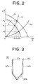
- Figure 2 is a graph of blowing performance of fans used in the automotive alternator according to Embodiment 1 of the present invention
- Figure 3 is a perspective of a U-shaped coil segment constituting a stator coil used in a stator of the automotive alternator according to Embodiment 1 of the present invention
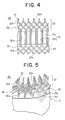
- Figure 4 is a partial side elevation of the stator with the coil segments installed
- Figure 5 is a partial perspective of the stator with the coil segments installed.
- portions which are identical or correspond to portions of the conventional automotive alternator shown in Figure 25 will be given identical numbering and explanation thereof will be omitted.
- a front-end fan 40 functioning as a front-end blowing means is fastened to a front-end surface of the front-end pole core 20 of the rotor 7, and a rear-end fan 41 functioning as a rear-end blowing means is fastened to a rear-end surface of the rear-end pole core 21 of the rotor 7.
- the front-end fan 40 has a blowing performance indicated by a curve A1 in Figure 2
- the rear-end fan 41 has a blowing performance indicated by a curve A2 in Figure 2.
- the rear-end fan 41 has a greater capacity than the front-end fan 40.
- the capacity of each fan is defined as the magnitude of a pressure difference upstream and downstream from the fan for a predetermined flow rate, capacity being to be considered greater if the resulting pressure difference is greater for an identical flow rate.
- a stator 35 is constituted by a stator core 15 and a stator coil 36.
- the stator coil is formed into a cylindrical shape, a plurality of teeth 15a having a generally rectangular cross-sectional shape are disposed at even angular pitch in a circumferential direction so as to protrude radially inwards, and slots 15b for housing the stator coil 36 are formed between the teeth 15a.
- Each of the slots 15b has grooves lying parallel to an axial direction, and is open on an inner circumferential side.
- the stator coil 36 is constructed by connecting a large number of short coil segments 30 so as to form a predetermined winding construction, for example, a three-phase alternating-current winding construction.
- a conductor such as copper having a rectangular cross section covered with an electrically-insulating coating is used for the coil segments 30, and each coil segment 30 is formed into a general U shape composed of a pair of straight portions 30a linked by a generally V-shaped turn portion 30b.
- each of the coil segments 30 is prepared such that the spacing between the pair of straight portions 30a is adjusted in advance to a spacing of three slots.
- the pairs of straight portions 30a of the coil segments 30 are inserted from the rear end of the stator core 15 into a set of pairs of slots 15b in which the slots in each pair are three slots away from each other, extending portions of the straight portions 30a extending outwards at the front end of the stator core 15 are bent, and then free end portions 30c are joined to each other so as to form one three-phase alternating-current winding overall, for example.
- the set of pairs of slots 15b in which the slots in each pair are three slots away from each other corresponds to a set of slots including a first slot and a fourth slot in a circumferential direction, for example.
- these coil segments 30 are inserted two at a time into each of the sets of slots 15b such that a height dimension of the turn portions 30b is aligned as shown in Figure 4.
- Four straight portions 30a are housed in each of the slots 15b so as to line up in one row radially with a longitudinal direction of their rectangular cross sections aligned radially.
- a first coil segment 30 is inserted into a first position from an outer circumferential side of a first slot 15b and a second position from the outer circumferential side of a second slot 15b, and a second coil segment 30 is inserted into a third position from the outer circumferential side of the first slot 15b and a fourth position from the outer circumferential side of the second slot 15b.
- An outer-layer winding is prepared by joining free end portions 30c of the coil segments 30 inserted into the first positions from the outer circumferential side of the slots 15b to free end portions 30c of other coil segments 30 inserted into the second positions from the outer circumferential side of slots 15b three slots away.
- An inner-layer winding is prepared by joining free end portions 30c of the coil segments 30 inserted into the third positions from the outer circumferential side of the slots 15b to free end portions 30c of other coil segments 30 inserted into the fourth positions from the outer circumferential side of slots 15b three slots away. Then, the outer-layer winding and the inner-layer winding are connected in series.
- the free end portions 30c of the coil segments 30 are stacked radially and joined to each other by generally fusing joint portions (tip portions of the free end portions 30c) by arc welding.
- the two joined free end portions 30c (joint portions 31) in the inner-layer winding and the two joined free end portions 30c (joint portions 31) in the outer-layer winding are lined up in one row radially.
- joint-end coil ends 32a constituted by the joint portion 31 ends of the coil segments 30 are arranged in two rows circumferentially to constitute a joint-end coil end group 32.
- the two free end portions 30c being joined are stacked together with the short sides of the rectangular cross sections thereof abutted, and are joined by fusing the whole of the tip portions by arc welding.
- Turn-end coil ends 33a formed by the turn portion 30b ends of the coil segments 30 are arranged in two rows circumferentially to constitute a turn-end coil end group 33.
- the stator 35 constructed in this manner is installed in an automotive alternator with the joint-end coil end group 32 constructed by joining the free end portions 30c of the coil segments 30 positioned at a front end and the turn-end coil end group 33 constituted by the turn portions 30b positioned at a rear end.
- the joint-end coil end group 32 of the stator coil 36 corresponds to a front-end coil end group 36f
- the turn-end coil end group 33 corresponds to a rear-end coil end group 36r.
- A1 is a blowing performance curve for the front-end fan 40
- A2 is a blowing performance curve for the rear-end fan 41
- Rf is an air flow passage pressure loss curve for the ventilation pathways in the front end
- Rr is an air flow passage pressure loss curve for the ventilation pathways in the rear end.
- the work point of the front-end fan 40 is the intersection between the curve A1 and the curve Rf
- the work point of the rear-end fan 41 is the intersection between the curve A2 and the curve Rr.
- a front-end air flow rate Q3 and a front-end air flow pressure P3 are achieved by the front-end fan 40
- a rear-end air flow rate Q2 and a rear-end air flow pressure P2 are achieved by the rear-end fan 41.
- Q2 is less than Q3 (Q2 ⁇ Q3)
- P2 is greater than P3 (P2 > P3).
- the front-end air flow rate of the cooling air flow flowing through the front-end ventilation pathway in which air enters the front bracket 1 through the front-end air intake apertures 1a, is deflected centrifugally by the front-end fan 40, and is then expelled through the front-end air discharge apertures 1b, is greater than the rear-end air flow rate of the cooling air flow flowing through the rear-end ventilation pathway, in which air enters the rear bracket 2 through the rear-end air intake apertures 2a, is deflected centrifugally by the rear-end fan 40, and is then expelled through the rear-end air discharge apertures 2b. Furthermore, a portion of the cooling air flow entering the front end flows to the rear end through the inside of the rotor 7.
- air flow pressure means the difference between the pressure generated in front of a resistant member disposed in the cooling air flow created by operation of the fan and that generated behind the resistant member. The greater the air flow pressure, the greater the capacity of the fan is enhanced.
- the work point of the rear-end fan 41 is (Q2, P2).
- the capacity of the rear-end fan 41 is set such that the rear-end air flow rate does not exceed the front-end air flow rate.
- the front-end air flow rate is greater than the rear-end air flow rate, and the capacity of the rear-end fan 41 is greater than the capacity of the front-end fan 40.
- the stator coil 36 can be sufficiently cooled, enabling temperature increases in the stator coil 36 to be suppressed.
- the capacity of the rear-end fan 41 is greater than the capacity of the front-end fan 40, the rear-end air flow rate is sufficiently ensured and the rectifier 12 and the regulator 18 can be sufficiently cooled, enabling temperature increases in the rectifier 12 and the regulator 18 to be suppressed. Consequently, the automotive alternator obtained enables overall cooling efficiency to be raised.
- the automotive alternator obtained enables worsening of wind noise to be suppressed.
- stator coil 36 is constructed by connecting a large number of short coil segments 30 having a rectangular cross section, the space factor of the coil segments 30 relative to the slots 15b can be raised, enabling the achievement of increased output.
- stator coil 36 obtained can be installed in the stator core by inserting the coil segments into the slots 15b from a first end of the stator core 15 and joining together the free end portions 30c extending outwards at a second end of the stator core 15.
- the stator coil 36 installed in the stator core 15 can be prepared easily.
- joint-end coil end group 32 has joint portions 31 in which heat dissipation is raised by removing the electrically-insulating coating and is disposed at the front end where the air flow rate is large, heat from the stator coil 36 is efficiently dissipated from the joint-end coil end group 32, effectively suppressing temperature increases in the stator coil 36.
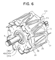
- Figure 6 is a perspective of Inventive Example 1 of a rotor used in the automotive alternator of the present invention
- Figures 7 and 8 are front elevations of a front-end fan 40A and a rear-end fan 41A, respectively, used in the rotor shown in Figure 6.
- the front-end and rear-end fans 40A and 41A were formed by working a thin metal sheet and were constituted by: annular fan base portions 40a and 41a; a number of blade base plates 40b and 41b extending radially outwards from outer circumferential edge portions of the fan base portions 40a and 41a; and blades 40c and 41c formed by folding an outer circumferential edge portion of each of the blade base plates 40b and 41b.
- the front-end intake air flow rate Qf IN was 0.05 m 3 /s
- the front-end discharge air flow rate Qf OUT was 0.048 m 3 /s
- the rear-end intake air flow rate Qr IN was 0.033 m 3 /s
- the rear-end discharge air flow rate Qr OUT was 0.035 m 3 /s
- the front-to-rear air flow rate Q f ⁇ r was 0.002 m 3 /s.
- Inventive Example 1 because the blade chord length (BLr) of the rear-end fan 41A were formed so as to be longer than the blade chord length (BLf) of the front-end fan 40A, the capacity of the rear-end fan 41A was greater than the capacity of the front-end fan 40A, and in addition, the front-end intake air flow rate Qf IN and the front-end discharge air flow rate Qf OUT were greater than the rear-end intake air flow rate Qr IN and the rear-end discharge air flow rate Qr OUT .
- the front-end and rear-end air flow rates were increased compared to the conventional example in which the number of blades was eight, enabling temperature increases in the stator coil 36, the rectifier 12, and the regulator 18 to be suppressed further.
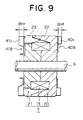
- the blade height (BHr) of a rear-end fan 41B was formed so as to be higher than the blade height (BHf) of a front-end fan 40B. Moreover, the rest of the construction was the same as in Inventive Example 1.
- the front-end intake air flow rate Qf IN was 0.05 m 3 /s
- the front-end discharge air flow rate Qf OUT was 0.045 m 3 /s
- the rear-end intake air flow rate Qr IN was 0.038 m 3 /s
- the rear-end discharge air flow rate Qr OUT was 0.043 m 3 /s
- the front-to-rear air flow rate Q f ⁇ r was 0.005 m 3 /s.
- the front-end intake air flow rate Qf IN and the front-end discharge air flow rate Qf OUT were also greater than the rear-end intake air flow rate Qr IN and the rear-end discharge air flow rate Qr OUT .
- a shielding plate 42 was mounted between the rear-end fan 41B and the rear-end pole core 21, blocking air gaps formed by valley portions between the rear-end claw-shaped magnetic poles 23 and by the blade base plates 41b. Moreover, the rest of the construction was the same as in Inventive Example 2.
- the front-end intake air flow rate Qf IN was 0.05 m 3 /s
- the front-end discharge air flow rate Qf OUT was 0.05 m 3 /s
- the rear-end intake air flow rate Qr IN was 0.045 m 3 /s
- the rear-end discharge air flow rate Qr OUT was 0.045 m 3 /s
- the front-to-rear air flow rate Q f ⁇ r was 0 m 3 /s.
- the front-end intake air flow rate Qf IN and the front-end discharge air flow rate Qf OUT were also greater than the rear-end intake air flow rate Qr IN and the rear-end discharge air flow rate Qr OUT .
- the front-to-rear air flow rate Q f ⁇ r was eliminated.
- the front-end intake air flow rate Qf IN was able to contribute to the cooling of the front-end coil end group without loss, temperature increases in the stator coil 36 could be reliably suppressed.
- the capacity of the rear-end fan 41B was raised further, increasing the rear-end intake air flow rate Qr IN , thereby enabling temperature increases in the rectifier 12 and the regulator 18 to be reliably suppressed.
- an outside diameter of a front-end fan 40 was formed so as to be smaller than an outside diameter of a rear-end fan 41. Moreover, the rest of the construction was the same as in Inventive Example 5.
- fans 40 and 41 were used as the front-end and rear-end blowing means, but in Inventive Example 8, the front-end pole core 20 was used as the front-end blowing means and a rear-end fan 41 was used as the rear-end blowing means.
- the capacity of the front-end pole core 20 as a blowing means was small compared to the rear-end fan 41, the capacity of the rear-end blowing means was also greater than the capacity of the front-end blowing means in Inventive Example 8, enabling the same effects to be achieved.
- fans 40 and 41 were used as the front-end and rear-end blowing means, but in Inventive Example 9, the front-end and rear-end pole cores 20 and 21 were used as the front-end and rear-end blowing means.
- front-end shoulder portions 22a were formed on the claw-shaped magnetic poles 22 of the front-end pole core 20 in an inclined plane having a predetermined angle relative to a front-end end surface of the front-end pole core 20 and intersecting the front-end end surface of the front-end pole core 20 on a circle centered on the axial center of the front-end pole core 20.
- rear-end shoulder portions 23a were formed on the claw-shaped magnetic poles 23 of the rear-end pole core 21 in an inclined plane having a predetermined angle relative to a rear-end end surface of the rear-end pole core 21 and having a line of intersection with the rear-end end surface of the rear-end pole core 21 which gradually approached the axial center of the rear-end pole core 21 backwards relative to the direction of rotation.
- the capacity of the rear-end pole core 21 as a blowing means was greater than the capacity of the front-end pole core 20 as a blowing means, enabling the fans 40 and 41 to be dispensed with, thereby enabling costs to be reduced further.
- the stator 35 is disposed such that a front-end axial height (CLf) of the front-end coil end group 36f of the stator coil 36 is greater than a rear-end axial height (CLr) of the rear-end coil end group 36r, and a front-end axial overlap (Of) between the front-end coil end group 36f and the front-end fan 40 is greater than a rear-end axial overlap (Or) between the rear-end coil end group 36r and the rear-end fan 41.
- CLf front-end axial height
- CLr rear-end axial height
- Or rear-end axial overlap
- the stator 35 is disposed such that the front-end axial height (CLf) of the front-end coil end group 36f of the stator coil 36 is greater than the rear-end axial height (CLr) of the rear-end coil end group 36r.
- CLf front-end axial height
- CLr rear-end axial height
- the stator 35 is also disposed such that the front-end axial overlap (Of) between the front-end coil end group 36f and the front-end fan 40 is greater than the rear-end axial overlap between the rear-end coil end group 36r and the rear-end fan 41.
- the volume of the coil end group exposed to the cooling air flow is increased in the front end where cooling efficiency is good, cooling the stator coil effectively.
- Embodiment 2 the overall cooling efficiency can be raised further and noise can be significantly decreased in Embodiment 2 as well by adopting the constructions from any of Inventive Examples 1 to 9 above.
- the coil segments 30 used were formed into a general U shape, but the present invention is not limited to coil segments 30 formed into a general U shape; the coil segments may be short conductor segments extending linearly.
- the stator coil was constructed by joining a large number of short coil segments 30 so as to adopt a predetermined overall winding construction, but in Embodiment 3, the stator coil is constructed so as to adopt a predetermined overall winding construction by linking a plurality of winding sub-portions each formed by installing one strand of wire composed of continuous wire into the stator core.
- Figure 19 is a perspective of a stator of an automotive alternator according to Embodiment 3 of the present invention. Connecting portions such as crossover-connections have been omitted from the diagram to facilitate explanation.
- the stator 81 includes: a stator core 50 composed of a cylindrical laminated core in which a plurality of teeth 50a having a generally rectangular cross sectional shape are disposed at even pitch in a circumferential direction so as to protrude radially inwards, slots 50b extending axially being formed between the teeth 50a; a stator coil 51 installed in the stator core 50; and insulators 52 mounted in the slots 50b for electrically insulating the stator coil 51 from the stator core 50.
- the stator coil 51 includes front-end and rear-end coil end groups 51f and 51r which extend outwards at a front end and a rear end of the stator core 50.
- the stator coil 51 is provided with two winding assemblies 60 disposed in two rows radially.
- the winding assemblies 60 are each constituted by two winding sub-portions in each of which one strand of wire 61 is folded over outside the slots 50b at end surfaces of the stator core 50 and wound into a wave winding so as to alternately occupy an inner layer and an outer layer in a slot depth direction within slots 50b a predetermined number of slots apart.
- the stator core 50 is formed with ninety-six slots 50b at even pitch so as to house two three-phase stator winding groups 53 (described below) such that the number of slots housing the two three-phase stator winding groups 53 corresponds to the number of magnetic poles (sixteen) in the rotor 7. In other words, the number of slots per phase per pole is two.
- Continuous wire of a copper wire material having a flat cross section coated with an electrically-insulating coating, for example, is used in the strands of wire 61.
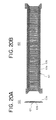
- Figure 20A is an end elevation of a winding assembly constituting a stator coil in the stator of the automotive alternator according to Embodiment 3 of the present invention
- Figure 20B is a plan of the winding assembly constituting the stator coil in the stator of the automotive alternator according to Embodiment 3 of the present invention
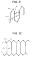
- Figure 21 is a perspective of part of a strand of wire constituting the stator coil in the stator of the automotive alternator according to Embodiment 3 of the present invention
- Figure 22 is a diagram explaining an arrangement of the strands of wire constituting the stator coil in the stator of the automotive alternator according to Embodiment 3 of the present invention.
- each strand of wire 61 constituting part of the winding assemblies 60 is formed into a planar pattern in which straight portions 61b connected by turn portions 61a are lined up at a pitch of six slots (6P). Adjacent straight portions 61b are offset by a distance equal to one width (W) of the strands of wire 61 and are linked by the turn portions 61a. As shown in Figure 22, two strands of wire 61 formed in the above pattern are offset by a pitch of six slots and arranged such that straight portions 61b thereof overlap to constitute a wire-strand pair.
- the winding assemblies 60 are constructed by arranging six wire-strand pairs arranged in the above manner so as to be offset by a pitch of one slot from each other.
- Six end portions of the strands of wire 61 each extend outwards from first and second sides at first and second ends of the winding assemblies 60.
- the turn portions 61a which constitute the coil ends are arranged so as to line up in rows on first and second side portions of the winding assemblies 60.
- the two winding assemblies 60 constructed in this manner are installed into the stator core 50 in two rows radially and each of the strands of wire 61 are joined so as to adopt the predetermined winding construction.
- the turn portions 61a of the strands of wire 61 extending outwards and folded over at end surfaces of the stator core 50 form the coil ends.
- the turn portions 61a which are formed into a substantially identical shape at both axial ends of the stator core 50 are mutually spaced circumferentially and radially, and arranged neatly in two rows circumferentially to form the front-end and rear-end coil end groups 51f and 51r.
- the winding assemblies 60 can be prepared by arranging 12 strands of the continuous wire, for example, at a pitch of one slot in a plane and simultaneously folding the twelve strands of continuous wire into a lightning-bolt shape in the plane, then folding the strands up perpendicularly using a jig. At this time, crossover connections, output wires, and neutral-point leads (not shown) are formed on the first and second side portions of the winding assemblies 60 by pulling out only predetermined strands of the continuous wire when the twelve strands of wire are being folded into the lightning-bolt shape.
- One stator winding phase portion 54 is constituted by first to fourth winding sub-portions 62 to 65 each composed of one strand of wire 61.
- the first winding sub-portion 62 is constructed into a wave winding in which one strand of wire 61 alternately occupies a first position from an inner circumferential side (a first address) and a second position from the inner circumferential side (a second address) inside the slots 50b in every sixth slot from Slot Numbers 1 to 91.
- the second winding sub-portion 63 is constructed into a wave winding in which a strand of wire 61 alternately occupies the second address and the first address inside the slots 50b in every sixth slot from Slot Numbers 1 to 91.
- the third winding sub-portion 64 is constructed into a wave winding in which a strand of wire 61alternately occupies a third position from the inner circumferential side (a third address) and a fourth position from the inner circumferential side (a fourth address) inside the slots 50b in every sixth slot from Slot Numbers 1 to 91.
- the fourth winding sub-portion 65 is constructed into a wave winding in which a strand of wire 61 alternately occupies the fourth address and the third address inside the slots 50b in every sixth slot from Slot Numbers 1 to 91.
- the first to fourth winding sub-portions 62 to 65 each constitute a winding sub-portion having one turn in which one strand of wire 61 is wound into every sixth slot 50b so as to alternately occupy an inner layer and an outer layer in a slot depth direction.
- Four strands of wire 61 are arranged to line up radially in one row within each slot 50b with the longitudinal direction of their rectangular cross sections aligned in a radial direction.
- a first end portion 63a of the second winding sub-portion 63 extending outwards from the second address of Slot Number 1 and a second end portion 65b of the fourth winding sub-portion 65 extending outwards from the third address of Slot Number 91 are joined, and in addition, a first end portion 65a of the fourth winding sub-portion 65 extending outwards from the fourth address of Slot Number 1 and a second end portion 63b of the second winding sub-portion 63 extending outwards from the first address of Slot Number 91 are joined to form a winding having two turns.
- a first end portion 62a of the first winding sub-portion 62 extending outwards from the first address of Slot Number 1 and a second end portion 64b of the third winding sub-portion 64 extending outwards from the fourth address of Slot Number 91 are joined, and in addition, a first end portion 64a of the third winding sub-portion 64 extending outwards from the third address of Slot Number 1 and a second end portion 62b of the first winding sub-portion 62 extending outwards from the second address of Slot Number 91 are joined to form a winding having two turns.
- a portion of the strand of wire 61 of the third winding sub-portion 64 extending outwards at the rear end of the stator core 50 from the third address of Slot Number 61 and the fourth address of Slot Number 67 is cut, and a portion of the strand of wire 61 of the fourth winding sub-portion 65 extending outwards at the rear end of the stator core 50 from the third address of Slot Number 67 and the fourth address of Slot Number 73 is also cut.
- a first cut end 64c of the third winding sub-portion 64 and a first cut end 65c of the fourth winding sub-portion 65 are joined to form one stator winding phase portion 54 having four turns connecting the first to fourth winding sub-portions 62 to 65 in series.
- the joint portion between the first cut end 64c of the third winding sub-portion 64 and the first cut end 65c of the fourth winding sub-portion 65 becomes a crossover connection connecting portion, and a second cut end 64d of the third winding sub-portion 64 and a second cut end 65d of the fourth winding sub-portion 65 become a neutral-point (N) and an output wire (O), respectively.
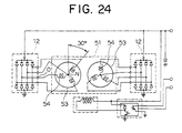
- a total of six stator winding phase portions 54 are similarly formed by offsetting by one slot at a time the slots 50b into which the strands of wire 61 are installed. Then, as shown in Figure 24, three stator winding phase portions 54 are connected into each of two star connections to form the two three-phase stator winding groups 53. Each of the three-phase stator winding groups 53 is connected to its own rectifier 12, and the rectifiers 12 are connected in parallel so that the direct-current output from each is combined.
- the strands of wire 61 constituting the first to fourth winding sub-portions 62 to 65 are each wound into a wave winding so as to extend out of first slots 50b at end surfaces of the stator core 50, fold back, and enter second slots 50b six slots away.
- Each of the strands of wire 61 is wound so as to alternately occupy the inner layer and the outer layer relative to the slot depth direction (the radial direction) in every sixth slot.
- the first winding sub-portions 62 and the second winding sub-portions 63 are inversely wound and offset by an electrical angle of 180° relative to each other and constitute the first winding assembly 60.
- the third winding sub-portions 43 and the fourth winding sub-portions 44 are inversely wound and offset by an electrical angle of 180° relative to each other and constitute the second winding assembly 60.
- Embodiment 3 is constructed similarly to Embodiment 1 above except for the fact that the stator 81 is used in place of the stator 8. Thus, the overall cooling efficiency can be raised further and noise can be significantly decreased in Embodiment 3 as well by adopting the constructions from any of Inventive Examples 1 to 9 above.
- the axial height of the turn portions 61a constituting the front-end coil end group may be made greater than the axial height of the turn portions 61a in the rear-end coil end group. In that case, the volume of the coil end group exposed to the cooling air flow is limited in the rear end, where cooling efficiency is poor, and the volume of the coil end group exposed to the cooling air flow is increased in the front end, where cooling efficiency is good, cooling the stator coil 51 effectively.
- the stator coil 51 is constructed by linking six stator winding phase portions 54 to form two three-phase stator winding groups 53.
- Each of the stator winding phase portions 54 is constructed from one strand of wire 61 constituted by a large number of straight portions 61b housed inside the slots 50b and a large number of turn portions 61a linking together end portions of adjacent straight portions 61b outside the slots 50b by housing the straight portions 61b in every sixth slot 50b so as to occupy different layers relative to a slot depth direction.
- Embodiment 3 the number of joints in the stator coil is significantly reduced compared to Embodiment 1 in which a large number of U-shaped coil segments 30 were used, enabling the productivity of the stator to be improved, and softening of the electrical conductors due to welding is eliminated, improving the rigidity of the stator, thereby enabling reducing magnetic noise to be reduced.
- one strand of wire 61 is wound into a wave winding having one turn per lap so as to alternately occupy different layers in every sixth slot, but the winding construction of the strand of wire is not limited to this; one strand of wire may be wound into a lap winding having two turns per lap so as to alternately occupy different layers in every sixth slot, for example.
- Each of the above embodiments uses coil segments 30 and strands of wire 61 having a rectangular cross section, but the coil segments and strands of wire are not limited to a rectangular cross section; they may have a circular cross section, or a portion of coil segments or strands of wire having a circular cross section may be formed with a rectangular cross section.
- the slots 15b (50b) are disposed at an even pitch, but it is not necessary to dispose the slots 15b (50b) at an even pitch; they may be disposed at an uneven pitch.
- the capacity (air flow pressure) of the rear-end fan is greater than the capacity of the front-end fan at all air flow rate points, but in practice, the capacity (air flow pressure) of the rear-end fan only needs to be greater than the capacity of the front-end fan in the working air flow region of the automotive alternator. Furthermore, it is not necessary to maintain this relationship for all rotational frequencies; the fans may be set to satisfy this relationship in rotational frequency regions where temperature and wind noise are a problem.
- the present invention is constructed in the above manner and exhibits the effects described below.
- an automotive alternator including:
- a front-end air discharge flow rate may be greater than a rear-end air discharge flow rate, further improving cooling efficiency by the cooling air flow, thereby reliably enabling the temperature of the stator coil and the rectifier to be lowered.
- an automotive alternator including:
- the front-to-rear ventilation pathway may be blocked, increasing the front-end air discharge flow rate, thereby enabling temperature increases in the stator coil to be further suppressed.
- the front-end and rear-end blowing means may be the Lundell-type pole cores or fans, enabling front-end and rear-end ventilation pathways to be formed in which cooling air flows flow axially into the front and rear brackets and are later expelled radially from the front and rear brackets.
- the front-end blowing means may be one of the Lundell-type pole cores and the rear-end blowing means may be a fan, enabling costs to be lowered.
- the front-end and rear-end blowing means may be fans, each fan comprising:
- the rear-end fan may be provided with a greater number of blades than the front-end fan, enabling the capacity of the rear-end fan to be made greater than that of the front-end fan.
- a maximum blade height of the rear-end fan may be greater than a maximum blade height of the front-end fan, enabling the capacity of the rear-end fan to be made greater than that of the front-end fan.
- the blade base plates of the rear-end fan may be formed into a shape which blocks valley portions between adjacent magnetic poles of the rotor, increasing the capacity of the rear-end fan and lowering the front-to-rear flow rate of the cooling air, thereby enabling cooling performance to be improved.
- a shielding plate may be disposed for blocking air gaps formed by the blade base plates of the rear-end fan and valley portions between adjacent magnetic poles of the rotor, increasing the capacity of the rear-end fan and lowering the front-to-rear flow rate of the cooling air, thereby enabling cooling performance to be improved.
- the stator coil may be constructed by:
- the joint-end coil end group of the stator coil may be disposed at the front end of the stator core, enabling the stator coil to be cooled effectively.
- the stator coil may be constructed by linking a plurality of winding sub-portions so as to constitute the predetermined winding construction, wherein each of the winding sub-portions is constituted by one strand of wire constituted by a large number of straight portions housed inside the slots and a large number of turn portions linking together end portions adjacent straight portions outside the slots, the strand of wire being installed in the stator core by housing the straight portions so as to form different layers relative to a slot depth direction in slots the predetermined number of slots apart, and coil ends formed by the turn portions are aligned in rows circumferentially to constitute front-end and rear-end coil end groups of the stator coil, enabling the number of joints in the stator coil to be significantly reduced, thereby enabling the productivity of the stator to be improved, and eliminating softening of the electrical conductors due to welding, thereby improving the rigidity of the stator and enabling reducing magnetic noise to be reduced.
Landscapes
- Engineering & Computer Science (AREA)
- Power Engineering (AREA)
- Motor Or Generator Cooling System (AREA)
- Windings For Motors And Generators (AREA)
- Synchronous Machinery (AREA)
Abstract
Description
- The present invention relates to an automotive alternator provided with a blowing means.
- The entire content of the basic Japanese Patent Application from which the priority under the Convention is claimed in this application is hereby incorporated by reference into this application.
- Figure 25 is a cross section of a conventional automotive alternator, and Figures 26 and 27 are front elevations showing a front-end fan and a rear-end fan, respectively, used in a rotor of the conventional automotive alternator.
- This automotive alternator is constructed by rotatably mounting a Lundell-
type rotor 7 by means of ashaft 6 inside acase 3 constructed from an aluminumfront bracket 1 and an aluminumrear bracket 2, and fastening a stator 8 to an inner wall of thecase 3 so as to cover an outer circumferential side of therotor 7. - The
shaft 6 is rotatably supported in thefront bracket 1 and therear bracket 2. Apulley 4 is fastened to a first end of thisshaft 6 such that rotational torque from an engine can be transmitted to theshaft 6 by means of a belt (not shown). -
Slip rings 9 for supplying electric current to therotor 7 are fastened to a second end of theshaft 6, and a pair ofbrushes 10 are housed in abrush holder 11 disposed inside thecase 3 such that the pair ofbrushes 10 slide in contact with theslip rings 9. Aregulator 18 for adjusting the magnitude of alternating voltage generated in the stator 8 is fastened by adhesive to aheat sink 17 fitted onto thebrush holder 11. Arectifier 12 which is electrically connected to the stator 8 and converts alternating current generated in the stator 8 into direct current is mounted inside thecase 3. - The
rotor 7 is composed of arotor coil 13 for generating magnetic flux on passage of electric current, and a pair of Lundell-type front-end and rear-end pole cores rotor coil 13, magnetic poles being formed in the front-end and rear-end pole cores rotor coil 13. The pair of front-end and rear-end pole cores magnetic poles end pole cores shaft 6 facing each other such that the front-end and rear-end claw-shapedmagnetic poles - The front-end and rear-
end fans fan base portion 5a, a number ofblade base plates 5b extending radially outwards from outer peripheral portions of thefan base portions 5a, andblades 5c formed by folding and bending an outer peripheral portion of each of theblade base plates 5b. The front-end and rear-end fans end pole cores - The stator 8 is constituted by a
stator core 15, and astator coil 16 formed by winding a conducting wire into thisstator core 15, alternating current being generated in thestator coil 16 by changes in magnetic flux from therotor 7 accompanying rotation of therotor 7. Portions of thestator coil 16 extend from front and rear axial ends of thestator core 15 and constitute a front-endcoil end group 16f and a rear-endcoil end group 16r. - In automotive alternators constructed in this manner, electric current is supplied from a battery (not shown) through the
brushes 10 and theslip rings 9 to therotor coil 13, generating magnetic flux. The front-end claw-shapedmagnetic poles 22 in the front-end pole core 20 are magnetized with north-seeking (N) poles by this magnetic flux, and the rear-end claw-shapedmagnetic poles 23 in the rear-end pole core 21 are magnetized with south-seeking (S) poles. At the same time, rotational torque from the engine is transmitted through the belt and thepulley 4 to theshaft 6, rotating therotor 7. Thus, a rotating magnetic field is applied to thestator coil 16, generating electromotive force in thestator coil 16. This alternating electromotive force passes through therectifier 12 and is rectified into direct current, the output thereof is adjusted by theregulator 18, and the battery is recharged. - In this automotive alternator, the
rotor coil 13, thestator coil 16, therectifier 12, and theregulator 18 continuously generate heat during power generation, and in an alternator having a rated output current in the 100A class, these components generate 60W, 500W, 120W, and 6W of heat energy, respectively, at rotational frequencies at which the temperature is high. - Thus, in order to cool the heat generated by power generation, front-end and rear-end
air intake apertures air discharge apertures front bracket 1 and therear bracket 2. More specifically, as shown in Figure 25, a number of the front-end and rear-endair intake apertures front bracket 1 and therear bracket 2, respectively, and a number of the front-end and rear-endair discharge apertures front bracket 1 and therear bracket 2, respectively. - At the rear end, as indicated by arrows in Figure 25, external air is sucked into the
case 3 through the rear-endair intake apertures 2a by rotation of the rear-end fans 5B, cooling therectifier 12 and theregulator 18, and is then deflected centrifugally by the rear-end fans 5B, cooling the rear-endcoil end group 16r of thestator coil 16 before being expelled to the outside through the rear-endair discharge apertures 2b. At the same time, at the front end, as indicated by arrows in Figure 25, external air is sucked into thecase 3 through the front-endair intake apertures 1a by rotation of the front-end fans 5A and is then deflected centrifugally by the front-end fans 5A, cooling the front-endcoil end group 16f of thestator coil 16 before being expelled to the outside through the front-endair discharge apertures 1b. In addition, a cooling air flow flows from the front end to the rear end as a result of a pressure difference between the front end and the rear end, cooling therotor coil 13. - When the conventional automotive alternator constructed in this manner is operated at a rotational frequency of 5000 rpm, the air flow rate in each of the ventilation pathways has been such that the front-end intake air flow rate QfIN was 0.025 m3/s, the front-end discharge air flow rate QfOUT was 0.02 m3/s, the rear-end intake air flow rate QrIN was 0.03 m3/s, the rear-end discharge air flow rate QrOUT was 0.035 m3/s, and the front-to-rear air flow rate Qf→r was 0.005 m3/s.
- This conventional automotive alternator is constructed such that the rear-end flow rates are greater than the front-end flow rates. Thus, at the rear end, because the large volume of cooling air taken in through the rear-end
air intake apertures 2a is warmed as it cools therectifier 12 and theregulator 18 and is then supplied for the cooling of the rear-endcoil end group 16r of thestator coil 16, temperature increases in the rear-endcoil end group 16r cannot be sufficiently suppressed. Similarly, at the front end, because the small volume of cooling air taken in through the front-endair intake apertures 1a is supplied for the cooling of the front-endcoil end group 16f of thestator coil 16, temperature increases in the front-endcoil end group 16f cannot be sufficiently suppressed. In other words, one problem has been that overall cooling efficiency has been low because the front-end flow rates have been too low to effectively cool thestator coil 16. - Now, fan-generated noise (SPL : Sound Pressure Level) is expressed by SPL = k + 10 log(P2.5 × Q), and is significantly affected by pressure loss P and by flow rate Q at the work point. Moreover, k is the specific sound level, being the noise per unit pressure and flow rate.
- The relationship between pressure loss (P), flow rate (Q), and wind resistance (r) is generally expressed by P = r × Q2.
- Thus, in the case of an identical flow rate, pressure loss becomes increasingly excessive as wind resistance increases, causing SPL to worsen significantly.
- Consequently, another problem in conventional automotive alternators has been that noise is increased because the flow rates in the rear end where the wind resistance is higher are greater than in the front end, as mentioned above.
- The present invention aims to solve the above problems and an object of the present invention is to provide an automotive alternator enabling overall cooling efficiency to be raised by making front-end flow rates capable of effectively cooling coil ends of a stator coil greater than rear-end flow rates so that the stator coil can be cooled sufficiently, and increasing the capacity of a rear-end blowing means relative to the capacity of a front-end blowing means to ensure rear-end flow rates so that a rectifier and a regulator are sufficiently cooled, and in addition, enabling noise to be reduced by making the flow rates in the front end, where wind resistance is small, greater than the flow rates in the rear end, where wind resistance is great.
- In order to achieve the above object, according to one aspect of the present invention, there is provided an automotive alternator including:
- a rotor fastened to a shaft rotatably supported by a front bracket and a rear bracket, the rotor having a pair of Lundell-type pole cores disposed inside the brackets;
- a stator supported by the brackets, the stator being disposed so as to
cover an outer circumference of the rotor, the stator comprising:
- a cylindrical stator core in which a plurality of slots having grooves lying in an axial direction are disposed circumferentially so as to open onto an inner circumferential side; and
- a stator coil installed in the stator core so as to constitute a predetermined winding construction;
- a pulley fastened to a front end of the shaft; and
- a rectifier disposed at a rear end of the rotor,
- wherein
- a plurality of front-end and rear-end air intake apertures are disposed in axial end surfaces of the front and rear brackets, respectively;
- a plurality of front-end and rear-end air discharge apertures are disposed in radial side surfaces of the front and rear brackets, respectively; and
- front-end and rear-end blowing means are disposed at front and rear
axial ends of the rotor, respectively,
- whereby a front-end ventilation pathway in which a cooling air flow flows through the front-end air intake apertures into the front-end bracket and flows out through the front-end air discharge apertures, a rear-end ventilation pathway in which a cooling air flow flows through the rear-end air intake apertures into the rear-end bracket and flows out through the rear-end air discharge apertures, and a front-to-rear ventilation pathway in which a cooling air flow flows through an inner side of the rotor between the front end and the rear end each is generated by operation of the blowing means,
- wherein a capacity of the rear-end blowing means is greater than a capacity of the front-end blowing means, and a front-end air intake flow rate is greater than a rear-end air intake flow rate.
-
- A front-end air discharge flow rate may be greater than a rear-end air discharge flow rate.
- According to another aspect of the present invention, there is provided an automotive alternator including:
- a rotor fastened to a shaft rotatably supported by a front bracket and a rear bracket, the rotor having a pair of Lundell-type pole cores disposed inside the brackets;
- a stator supported by the brackets, the stator being disposed so as to
cover an outer circumference of the rotor, the stator comprising:
- a cylindrical stator core in which a plurality of slots having grooves lying in an axial direction are disposed circumferentially so as to open onto an inner circumferential side; and
- a stator coil installed in the stator core so as to constitute a predetermined winding construction;
- a pulley fastened to a front end of the shaft; and
- a rectifier disposed at a rear end of the rotor,
wherein - a plurality of front-end and rear-end air intake apertures are disposed in axial end surfaces of the front and rear brackets, respectively;
- a plurality of front-end and rear-end air discharge apertures are disposed in radial side surfaces of the front and rear brackets, respectively; and
- front-end and rear-end blowing means are disposed at front and rear
axial ends of the rotor, respectively,
- whereby a front-end ventilation pathway in which a cooling air flow flows through the front-end air intake apertures into the front-end bracket and flows out through the front-end air discharge apertures, a rear-end ventilation pathway in which a cooling air flow flows through the rear-end air intake apertures into the rear-end bracket and flows out through the rear-end air discharge apertures, and a front-to-rear ventilation pathway in which a cooling air flow flows through an inner side of the rotor between the front end and the rear end each is generated by operation of the blowing means,
- wherein a capacity of the rear-end blowing means is greater than a capacity of the front-end blowing means, and a front-end air discharge flow rate is greater than a rear-end air discharge flow rate.
-
- The front-to-rear ventilation pathway may be blocked.
- The front-end and rear-end blowing means may be the Lundell-type pole cores or fans.
- The front-end blowing means may be one of the Lundell-type pole cores and the rear-end blowing means may be a fan.
- The front-end and rear-end blowing means may be fans, each fan comprising:
- a generally annular fan base portion;
- a plurality of blade base plates extending radially outwards from outer circumferential edge portions of the fan base portion; and
- a plurality of blades standing on an outer circumferential edge portion of each of the plurality of blade base plates.
-
- The rear-end fan may be provided with a greater number of blades than the front-end fan.
- A maximum blade height of the rear-end fan may be greater than a maximum blade height of the front-end fan.
- The blade base plates of the rear-end fan may be formed into a shape which blocks valley portions between adjacent magnetic poles of the rotor.
- A shielding plate may be disposed for blocking air gaps formed by the blade base plates of the rear-end fan and valley portions between adjacent magnetic poles of the rotor.
- The stator coil may be constructed by:
- inserting coil segments composed of short conductors formed into a general U shape from a first end of the stator core into slot pairs in which the slots in each pair are a predetermined number of slots apart; and
- circumferentially bending and joining together free end portions of the coil segments extending outwards at a second end of the stator core from slots the predetermined number of slots apart so as to constitute the predetermined winding construction,
- wherein turn-end coil ends formed by U-shaped turn ends of the coil segments are aligned in rows circumferentially to constitute a turn-end coil end group, and joint-end coil ends formed by the joining of the free end portions of the coil segments are aligned in rows circumferentially to constitute a joint-end coil end group.
-
- The joint-end coil end group of the stator coil may be disposed at the front end of the stator core.
- The stator coil may be constructed by linking a plurality of winding sub-portions so as to constitute the predetermined winding construction,
wherein each of the winding sub-portions is constituted by one strand of wire constituted by a large number of straight portions housed inside the slots and a large number of turn portions linking together end portions adjacent straight portions outside the slots, the strand of wire being installed in the stator core by housing the straight portions so as to form different layers relative to a slot depth direction in slots the predetermined number of slots apart, and coil ends formed by the turn portions are aligned in rows circumferentially to constitute front-end and rear-end coil end groups of the stator coil. -
- Figure 1 is a cross section of a construction of an automotive
alternator according to
Embodiment 1 of the present invention; - Figure 2 is a graph of blowing performance of fans used in the
automotive alternator according to
Embodiment 1 of the present invention; - Figure 3 is a perspective of a coil segment used in a stator of the
automotive alternator according to
Embodiment 1 of the present invention; - Figure 4 is a partial side elevation of the stator with the coil segments installed;
- Figure 5 is a partial perspective of the stator with the coil segments installed;
- Figure 6 is a perspective of a rotor according to Inventive Example 1 of the present invention;
- Figure 7 is a front elevation of a front-end fan according to Inventive Example 1 of the present invention;
- Figure 8 is a front elevation of a rear-end fan according to Inventive Example 1 of the present invention;
- Figure 9 is a cross section of a rotor according to Inventive Example 2 of the present invention;
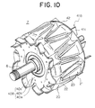
- Figure 10 is a perspective of a rotor according to Inventive Example 3 of the present invention;
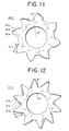
- Figure 11 is a front elevation of a front-end fan according to Inventive Example 4 of the present invention;
- Figure 12 is a front elevation of a rear-end fan according to Inventive Example 4 of the present invention;
- Figure 13 is a front elevation of a front-end fan according to Inventive Example 5 of the present invention;
- Figure 14 is a front elevation of a rear-end fan according to Inventive Example 5 of the present invention;
- Figure 15 is a front elevation of a mounted state of a rear-end fan according to Inventive Example 6 of the present invention;
- Figure 16 is a perspective of a front-end pole core according to Inventive Example 9 of the present invention;
- Figure 17 is a perspective of a rear-end pole core according to Inventive Example 9 of the present invention;
- Figure 18 is a partial cross section of an automotive alternator
according to
Embodiment 2 of the present invention; - Figure 19 is a perspective of a stator used in an automotive
alternator according to
Embodiment 3 of the present invention; - Figure 20A is an end elevation of a winding assembly constituting a
stator coil in the stator of the automotive alternator according to
Embodiment 3 of the present invention; - Figure 20B is a plan of the winding assembly constituting the stator
coil in the stator of the automotive alternator according to
Embodiment 3 of the present invention; - Figure 21 is a perspective of part of a strand of wire constituting the
stator coil in the stator of the automotive alternator according to
Embodiment 3 of the present invention; - Figure 22 is a diagram explaining an arrangement of the strands of
wire constituting the stator coil in the stator of the automotive alternator
according to
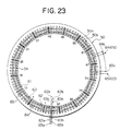
Embodiment 3 of the present invention; - Figure 23 is an end elevation explaining connections in one stator
coil phase portion in the stator of the automotive alternator according to
Embodiment 3 of the present invention; - Figure 24 is a circuit diagram of the stator of the automotive
alternator according to
Embodiment 3 of the present invention; - Figure 25 is a cross section of a construction of a conventional automotive alternator;
- Figure 26 is a front elevation of a conventional front-end fan; and
- Figure 27 is a front elevation of a conventional rear-end fan.
-
- The preferred embodiments of the present invention will now be explained with reference to the drawings.
- Figure 1 is a cross section of a construction of an automotive alternator according to
Embodiment 1 of the present invention, Figure 2 is a graph of blowing performance of fans used in the automotive alternator according toEmbodiment 1 of the present invention, Figure 3 is a perspective of a U-shaped coil segment constituting a stator coil used in a stator of the automotive alternator according toEmbodiment 1 of the present invention, Figure 4 is a partial side elevation of the stator with the coil segments installed, and Figure 5 is a partial perspective of the stator with the coil segments installed. Moreover, in each of the figures, portions which are identical or correspond to portions of the conventional automotive alternator shown in Figure 25 will be given identical numbering and explanation thereof will be omitted. - In each of the figures, a front-
end fan 40 functioning as a front-end blowing means is fastened to a front-end surface of the front-end pole core 20 of therotor 7, and a rear-end fan 41 functioning as a rear-end blowing means is fastened to a rear-end surface of the rear-end pole core 21 of therotor 7. The front-end fan 40 has a blowing performance indicated by a curve A1 in Figure 2, and the rear-end fan 41 has a blowing performance indicated by a curve A2 in Figure 2. In other words the rear-end fan 41 has a greater capacity than the front-end fan 40. Moreover, the capacity of each fan is defined as the magnitude of a pressure difference upstream and downstream from the fan for a predetermined flow rate, capacity being to be considered greater if the resulting pressure difference is greater for an identical flow rate. - A
stator 35 is constituted by astator core 15 and astator coil 36. The stator coil is formed into a cylindrical shape, a plurality ofteeth 15a having a generally rectangular cross-sectional shape are disposed at even angular pitch in a circumferential direction so as to protrude radially inwards, andslots 15b for housing thestator coil 36 are formed between theteeth 15a. Each of theslots 15b has grooves lying parallel to an axial direction, and is open on an inner circumferential side. - The
stator coil 36 is constructed by connecting a large number ofshort coil segments 30 so as to form a predetermined winding construction, for example, a three-phase alternating-current winding construction. A conductor such as copper having a rectangular cross section covered with an electrically-insulating coating is used for thecoil segments 30, and eachcoil segment 30 is formed into a general U shape composed of a pair ofstraight portions 30a linked by a generally V-shapedturn portion 30b. Furthermore, each of thecoil segments 30 is prepared such that the spacing between the pair ofstraight portions 30a is adjusted in advance to a spacing of three slots. The pairs ofstraight portions 30a of thecoil segments 30 are inserted from the rear end of thestator core 15 into a set of pairs ofslots 15b in which the slots in each pair are three slots away from each other, extending portions of thestraight portions 30a extending outwards at the front end of thestator core 15 are bent, and thenfree end portions 30c are joined to each other so as to form one three-phase alternating-current winding overall, for example. Moreover, the set of pairs ofslots 15b in which the slots in each pair are three slots away from each other corresponds to a set of slots including a first slot and a fourth slot in a circumferential direction, for example. - Here, these
coil segments 30 are inserted two at a time into each of the sets ofslots 15b such that a height dimension of theturn portions 30b is aligned as shown in Figure 4. Fourstraight portions 30a are housed in each of theslots 15b so as to line up in one row radially with a longitudinal direction of their rectangular cross sections aligned radially. - In each of the sets of
slots 15b, afirst coil segment 30 is inserted into a first position from an outer circumferential side of afirst slot 15b and a second position from the outer circumferential side of asecond slot 15b, and asecond coil segment 30 is inserted into a third position from the outer circumferential side of thefirst slot 15b and a fourth position from the outer circumferential side of thesecond slot 15b. An outer-layer winding is prepared by joiningfree end portions 30c of thecoil segments 30 inserted into the first positions from the outer circumferential side of theslots 15b tofree end portions 30c ofother coil segments 30 inserted into the second positions from the outer circumferential side ofslots 15b three slots away. An inner-layer winding is prepared by joiningfree end portions 30c of thecoil segments 30 inserted into the third positions from the outer circumferential side of theslots 15b tofree end portions 30c ofother coil segments 30 inserted into the fourth positions from the outer circumferential side ofslots 15b three slots away. Then, the outer-layer winding and the inner-layer winding are connected in series. - The
free end portions 30c of thecoil segments 30 are stacked radially and joined to each other by generally fusing joint portions (tip portions of thefree end portions 30c) by arc welding. The two joinedfree end portions 30c (joint portions 31) in the inner-layer winding and the two joinedfree end portions 30c (joint portions 31) in the outer-layer winding are lined up in one row radially. Thus, joint-end coil ends 32a constituted by thejoint portion 31 ends of thecoil segments 30 are arranged in two rows circumferentially to constitute a joint-endcoil end group 32. - At this time, the two
free end portions 30c being joined are stacked together with the short sides of the rectangular cross sections thereof abutted, and are joined by fusing the whole of the tip portions by arc welding. - Turn-end coil ends 33a formed by the
turn portion 30b ends of thecoil segments 30 are arranged in two rows circumferentially to constitute a turn-endcoil end group 33. - The
stator 35 constructed in this manner is installed in an automotive alternator with the joint-endcoil end group 32 constructed by joining thefree end portions 30c of thecoil segments 30 positioned at a front end and the turn-endcoil end group 33 constituted by theturn portions 30b positioned at a rear end. In other words, the joint-endcoil end group 32 of thestator coil 36 corresponds to a front-endcoil end group 36f, and the turn-endcoil end group 33 corresponds to a rear-endcoil end group 36r. - Next, the work points of the
fans Embodiments 1 will be explained with reference to Figure 2. In Figure 2, A1 is a blowing performance curve for the front-end fan 40, A2 is a blowing performance curve for the rear-end fan 41, Rf is an air flow passage pressure loss curve for the ventilation pathways in the front end, and Rr is an air flow passage pressure loss curve for the ventilation pathways in the rear end. - From Figure 2, the work point of the front-
end fan 40 is the intersection between the curve A1 and the curve Rf, and the work point of the rear-end fan 41 is the intersection between the curve A2 and the curve Rr. In other words, a front-end air flow rate Q3 and a front-end air flow pressure P3 are achieved by the front-end fan 40, and a rear-end air flow rate Q2 and a rear-end air flow pressure P2 are achieved by the rear-end fan 41. Moreover, Q2 is less than Q3 (Q2 < Q3), and P2 is greater than P3 (P2 > P3). - Thus, the front-end air flow rate of the cooling air flow flowing through the front-end ventilation pathway, in which air enters the
front bracket 1 through the front-endair intake apertures 1a, is deflected centrifugally by the front-end fan 40, and is then expelled through the front-endair discharge apertures 1b, is greater than the rear-end air flow rate of the cooling air flow flowing through the rear-end ventilation pathway, in which air enters therear bracket 2 through the rear-endair intake apertures 2a, is deflected centrifugally by the rear-end fan 40, and is then expelled through the rear-endair discharge apertures 2b. Furthermore, a portion of the cooling air flow entering the front end flows to the rear end through the inside of therotor 7. - Here, "air flow pressure" means the difference between the pressure generated in front of a resistant member disposed in the cooling air flow created by operation of the fan and that generated behind the resistant member. The greater the air flow pressure, the greater the capacity of the fan is enhanced.
- Now, if fans having the blowing performance curve A1 are used for the fans in both the front end and the rear end, the work points of the front-end and rear-end fans are (Q3, P3) and (Q1, P1), respectively. Moreover, Q1 < Q2 < Q3, and P2 > P1 > P3.
- When a fan having the blowing performance curve A2 is used for the rear-
end fan 41, the work point of the rear-end fan 41 is (Q2, P2). In other words, by increasing the capacity of the rear-end fan 41, the rear-end air flow rate can be raised from Q1 to Q2. In this case, the capacity of the rear-end fan 41 is set such that the rear-end air flow rate does not exceed the front-end air flow rate. - In this manner, in
Embodiment 1, the front-end air flow rate is greater than the rear-end air flow rate, and the capacity of the rear-end fan 41 is greater than the capacity of the front-end fan 40. - Because the front-end air flow rate capable of effectively cooling the coil end group of the
stator coil 36 is greater than the rear-end air flow rate, thestator coil 36 can be sufficiently cooled, enabling temperature increases in thestator coil 36 to be suppressed. In addition, because the capacity of the rear-end fan 41 is greater than the capacity of the front-end fan 40, the rear-end air flow rate is sufficiently ensured and therectifier 12 and theregulator 18 can be sufficiently cooled, enabling temperature increases in therectifier 12 and theregulator 18 to be suppressed. Consequently, the automotive alternator obtained enables overall cooling efficiency to be raised. - In addition, because the air flow rate at the front end where wind resistance is small is made greater than the air flow rate at the rear end where wind resistance is great, the automotive alternator obtained enables worsening of wind noise to be suppressed.
- Because the
stator coil 36 is constructed by connecting a large number ofshort coil segments 30 having a rectangular cross section, the space factor of thecoil segments 30 relative to theslots 15b can be raised, enabling the achievement of increased output. - Because the
coil segments 30 are formed into the general U shape, thestator coil 36 obtained can be installed in the stator core by inserting the coil segments into theslots 15b from a first end of thestator core 15 and joining together thefree end portions 30c extending outwards at a second end of thestator core 15. Thus, thestator coil 36 installed in thestator core 15 can be prepared easily. - Because the joint-end
coil end group 32 hasjoint portions 31 in which heat dissipation is raised by removing the electrically-insulating coating and is disposed at the front end where the air flow rate is large, heat from thestator coil 36 is efficiently dissipated from the joint-endcoil end group 32, effectively suppressing temperature increases in thestator coil 36. - The fan construction used in the automotive alternator according to the present invention will now be explained in detail.
- Figure 6 is a perspective of Inventive Example 1 of a rotor used in the automotive alternator of the present invention, and Figures 7 and 8 are front elevations of a front-
end fan 40A and a rear-end fan 41A, respectively, used in the rotor shown in Figure 6. - The front-end and rear-
end fans fan base portions blade base plates fan base portions blades blade base plates fans end fan 41A was formed so as to be longer than a blade chord length (BLf) of the front-end fan 40A, making the capacity of the rear-end fan 41A greater than the capacity of the front-end fan 40A. That is, Df = Dr, Nf = Nr, BHf = BHr, and BLf < BLr. - When an automotive alternator fitted with a rotor mounted with the
fans - According to Inventive Example 1, because the blade chord length (BLr) of the rear-
end fan 41A were formed so as to be longer than the blade chord length (BLf) of the front-end fan 40A, the capacity of the rear-end fan 41A was greater than the capacity of the front-end fan 40A, and in addition, the front-end intake air flow rate QfIN and the front-end discharge air flow rate QfOUT were greater than the rear-end intake air flow rate QrIN and the rear-end discharge air flow rate QrOUT. - Consequently, the effects of
Embodiment 1 above were achieved. - Furthermore, because the number of blades in each of the front-end and rear-
end fans stator coil 36, therectifier 12, and theregulator 18 to be suppressed further. - As shown in Figure 9, in Inventive Example 2, the blade height (BHr) of a rear-
end fan 41B was formed so as to be higher than the blade height (BHf) of a front-end fan 40B. Moreover, the rest of the construction was the same as in Inventive Example 1. - When an automotive alternator fitted with a rotor mounted with the
fans - In Inventive Example 2, the front-end intake air flow rate QfIN and the front-end discharge air flow rate QfOUT were also greater than the rear-end intake air flow rate QrIN and the rear-end discharge air flow rate QrOUT.
- Furthermore, in Inventive Example 2, because the blade height (BHr) of the rear-
end fan 41B was formed so as to be higher than the blade height (BHf) of the front-end fan 40B, the capacity of the rear-end fan 41B was even greater than the capacity of the front-end fan 40B, making the rear-end intake air flow rate QrIN and the rear-end discharge air flow rate QrOUT greater than in Inventive Example 1 above. - Thus, temperature increases in the
rectifier 12 and theregulator 18 were suppressed further than in Inventive Example 1. - As shown in Figure 10, a shielding
plate 42 was mounted between the rear-end fan 41B and the rear-end pole core 21, blocking air gaps formed by valley portions between the rear-end claw-shapedmagnetic poles 23 and by theblade base plates 41b. Moreover, the rest of the construction was the same as in Inventive Example 2. - When an automotive alternator fitted with a rotor constructed in this manner was operated at a rotational frequency of 5000 rpm, the front-end intake air flow rate QfIN was 0.05 m3/s, the front-end discharge air flow rate QfOUT was 0.05 m3/s, the rear-end intake air flow rate QrIN was 0.045 m3/s, the rear-end discharge air flow rate QrOUT was 0.045 m3/s, and the front-to-rear air flow rate Qf→r was 0 m3/s.
- In Inventive Example 3, the front-end intake air flow rate QfIN and the front-end discharge air flow rate QfOUT were also greater than the rear-end intake air flow rate QrIN and the rear-end discharge air flow rate QrOUT.
- Because the ventilation pathway of the cooling air flow flowing from the front-end to the rear-end was blocked by the shielding
plate 42, the front-to-rear air flow rate Qf→r was eliminated. Thus, because the front-end intake air flow rate QfIN was able to contribute to the cooling of the front-end coil end group without loss, temperature increases in thestator coil 36 could be reliably suppressed. Because the spaces formed between theblade base plates 41b were blocked by the shieldingplate 42, the capacity of the rear-end fan 41B was raised further, increasing the rear-end intake air flow rate QrIN, thereby enabling temperature increases in therectifier 12 and theregulator 18 to be reliably suppressed. - As shown in Figures 11 and 12, in Inventive Example 4, a front-
end fan 40C and a rear-end fan 41C had identical outside diameters (Df and Dr), blade heights (BHf and BHr), and blade chord lengths (BLf and BLr), the number of blades (Nf) in the front-end fan 40C was eight, and the number of blades (Nr) in the rear-end fan 41C was ten. That is, Df = Dr, Nf < Nr, BHf = BHr, and BLf = BLr. - Consequently, in Inventive Example 4, because a fan having a greater number of blades than the number of blades in the front-
end fan 40C was used for the rear-end fan 41C, the capacity of the rear-end fan 41C was also greater than the capacity of the front-end fan 40C, enabling the effects ofEmbodiment 1 above to be achieved. - As shown in Figures 13 and 14, in Inventive Example 5, a front-
end fan 40D and a rear-end fan 41D had identical outside diameters (Df and Dr), blade heights (BHf and BHr), and numbers of blades (Nf and Nr), and the blade chord length (BLr) of the rear-end fan 41D was formed so as to be longer than the blade chord length (BLf) of the front-end fan 40D. That is, Df = Dr, Nf = Nr, BHf = BHr, and BLf < BLr. - Consequently, in Inventive Example 5, because a fan having a longer blade chord length than the blade chord length of the front-
end fan 40D was used for the rear-end fan 41D, the capacity of the rear-end fan 41C was also greater than the capacity of the front-end fan 40C, enabling the effects ofEmbodiment 1 above to be achieved. - As shown in Figure 15, in Inventive Example 6, the
blade base plates 41b of a rear-end fan 41E were enlarged, and the rear-end fan 41E were fastened to the rear-end pole core 21 such that the enlargedblade base plates 41b covered the valley portions between adjacent rear-end claw-shapedmagnetic poles 23. Moreover, the rest of the construction was the same as in Inventive Example 5. - In Inventive Example 6, because the valley portions between adjacent rear-end claw-shaped
magnetic poles 23 were blocked by theblade base plates 41b when viewed axially, the front-to-rear air flow rate Qf→r was limited. Thus, because the front-end intake air flow rate QfIN was able to contribute to the cooling of the front-end coil end group with limited loss, temperature increases in thestator coil 36 could be further suppressed. Because the spaces formed between theblade base plates 41b were blocked by end surfaces of the rear-end claw-shapedmagnetic poles 23, the capacity of the rear-end fan 41E was raised further, increasing the rear-end intake air flow rate QrIN, thereby enabling temperature increases in therectifier 12 and theregulator 18 to be reliably suppressed. - In Inventive Example 7, an outside diameter of a front-
end fan 40 was formed so as to be smaller than an outside diameter of a rear-end fan 41. Moreover, the rest of the construction was the same as in Inventive Example 5. - Consequently, in Inventive Example 7, because a fan having a smaller outside diameter than the outside diameter of the rear-
end fan 41 was used for the front-end fan 40, the capacity of the rear-end fan 41 was also greater than the capacity of the front-end fan 40, enabling the effects ofEmbodiment 1 above to be achieved. - In each of the above inventive examples,
fans end pole core 20 was used as the front-end blowing means and a rear-end fan 41 was used as the rear-end blowing means. - Here, because the capacity of the front-
end pole core 20 as a blowing means was small compared to the rear-end fan 41, the capacity of the rear-end blowing means was also greater than the capacity of the front-end blowing means in Inventive Example 8, enabling the same effects to be achieved. - Furthermore, because the front-end fan was eliminated, costs could be reduced.
- In Inventive Examples 1 to 7 above,
fans end pole cores - In Inventive Example 9, as shown in Figure 16, front-
end shoulder portions 22a were formed on the claw-shapedmagnetic poles 22 of the front-end pole core 20 in an inclined plane having a predetermined angle relative to a front-end end surface of the front-end pole core 20 and intersecting the front-end end surface of the front-end pole core 20 on a circle centered on the axial center of the front-end pole core 20. On the other hand, as shown in Figure 17, rear-end shoulder portions 23a were formed on the claw-shapedmagnetic poles 23 of the rear-end pole core 21 in an inclined plane having a predetermined angle relative to a rear-end end surface of the rear-end pole core 21 and having a line of intersection with the rear-end end surface of the rear-end pole core 21 which gradually approached the axial center of the rear-end pole core 21 backwards relative to the direction of rotation. - Thus, due to the differences in the shapes of the
shoulder portions 22a and 23a of the front-end and rear-end claw-shapedmagnetic poles end pole core 21 as a blowing means was greater than the capacity of the front-end pole core 20 as a blowing means, enabling thefans - As shown in Figure 18, in
Embodiment 2, thestator 35 is disposed such that a front-end axial height (CLf) of the front-endcoil end group 36f of thestator coil 36 is greater than a rear-end axial height (CLr) of the rear-endcoil end group 36r, and a front-end axial overlap (Of) between the front-endcoil end group 36f and the front-end fan 40 is greater than a rear-end axial overlap (Or) between the rear-endcoil end group 36r and the rear-end fan 41. In other words, CLr < CLf and Or < Of. Moreover, the rest of the construction is the same as inEmbodiment 1. - According to
Embodiment 2, thestator 35 is disposed such that the front-end axial height (CLf) of the front-endcoil end group 36f of thestator coil 36 is greater than the rear-end axial height (CLr) of the rear-endcoil end group 36r. Thus, the volume of the coil end group exposed to the cooling air flow is limited in the rear end where cooling efficiency is poor, and the volume of the coil end group exposed to the cooling air flow is increased in the front end where cooling efficiency is good, cooling thestator coil 36 effectively. - The
stator 35 is also disposed such that the front-end axial overlap (Of) between the front-endcoil end group 36f and the front-end fan 40 is greater than the rear-end axial overlap between the rear-endcoil end group 36r and the rear-end fan 41. Thus, the volume of the coil end group exposed to the cooling air flow is increased in the front end where cooling efficiency is good, cooling the stator coil effectively. - Naturally, the overall cooling efficiency can be raised further and noise can be significantly decreased in
Embodiment 2 as well by adopting the constructions from any of Inventive Examples 1 to 9 above. - Moreover, in
Embodiments coil segments 30 used were formed into a general U shape, but the present invention is not limited tocoil segments 30 formed into a general U shape; the coil segments may be short conductor segments extending linearly. - In
Embodiments short coil segments 30 so as to adopt a predetermined overall winding construction, but inEmbodiment 3, the stator coil is constructed so as to adopt a predetermined overall winding construction by linking a plurality of winding sub-portions each formed by installing one strand of wire composed of continuous wire into the stator core. - Figure 19 is a perspective of a stator of an automotive alternator according to
Embodiment 3 of the present invention. Connecting portions such as crossover-connections have been omitted from the diagram to facilitate explanation. - In Figure 19, the
stator 81 includes: astator core 50 composed of a cylindrical laminated core in which a plurality ofteeth 50a having a generally rectangular cross sectional shape are disposed at even pitch in a circumferential direction so as to protrude radially inwards,slots 50b extending axially being formed between theteeth 50a; astator coil 51 installed in thestator core 50; andinsulators 52 mounted in theslots 50b for electrically insulating thestator coil 51 from thestator core 50. Thestator coil 51 includes front-end and rear-endcoil end groups stator core 50. - Furthermore, the
stator coil 51 is provided with two windingassemblies 60 disposed in two rows radially. The windingassemblies 60 are each constituted by two winding sub-portions in each of which one strand ofwire 61 is folded over outside theslots 50b at end surfaces of thestator core 50 and wound into a wave winding so as to alternately occupy an inner layer and an outer layer in a slot depth direction withinslots 50b a predetermined number of slots apart. In this case, thestator core 50 is formed with ninety-sixslots 50b at even pitch so as to house two three-phase stator winding groups 53 (described below) such that the number of slots housing the two three-phasestator winding groups 53 corresponds to the number of magnetic poles (sixteen) in therotor 7. In other words, the number of slots per phase per pole is two. Continuous wire of a copper wire material having a flat cross section coated with an electrically-insulating coating, for example, is used in the strands ofwire 61. - The construction of the winding
assemblies 60 will be explained here in detail with reference to Figures 20A to 22. Figure 20A is an end elevation of a winding assembly constituting a stator coil in the stator of the automotive alternator according toEmbodiment 3 of the present invention, Figure 20B is a plan of the winding assembly constituting the stator coil in the stator of the automotive alternator according toEmbodiment 3 of the present invention, Figure 21 is a perspective of part of a strand of wire constituting the stator coil in the stator of the automotive alternator according toEmbodiment 3 of the present invention, and Figure 22 is a diagram explaining an arrangement of the strands of wire constituting the stator coil in the stator of the automotive alternator according toEmbodiment 3 of the present invention. - As shown in Figure 21, each strand of
wire 61 constituting part of the windingassemblies 60 is formed into a planar pattern in whichstraight portions 61b connected byturn portions 61a are lined up at a pitch of six slots (6P). Adjacentstraight portions 61b are offset by a distance equal to one width (W) of the strands ofwire 61 and are linked by theturn portions 61a. As shown in Figure 22, two strands ofwire 61 formed in the above pattern are offset by a pitch of six slots and arranged such thatstraight portions 61b thereof overlap to constitute a wire-strand pair. As shown in Figures 20A and 20B, the windingassemblies 60 are constructed by arranging six wire-strand pairs arranged in the above manner so as to be offset by a pitch of one slot from each other. Six end portions of the strands ofwire 61 each extend outwards from first and second sides at first and second ends of the windingassemblies 60. Furthermore, theturn portions 61a which constitute the coil ends are arranged so as to line up in rows on first and second side portions of the windingassemblies 60. - The two winding
assemblies 60 constructed in this manner are installed into thestator core 50 in two rows radially and each of the strands ofwire 61 are joined so as to adopt the predetermined winding construction. Theturn portions 61a of the strands ofwire 61 extending outwards and folded over at end surfaces of thestator core 50 form the coil ends. Theturn portions 61a which are formed into a substantially identical shape at both axial ends of thestator core 50 are mutually spaced circumferentially and radially, and arranged neatly in two rows circumferentially to form the front-end and rear-endcoil end groups - The winding
assemblies 60 can be prepared by arranging 12 strands of the continuous wire, for example, at a pitch of one slot in a plane and simultaneously folding the twelve strands of continuous wire into a lightning-bolt shape in the plane, then folding the strands up perpendicularly using a jig. At this time, crossover connections, output wires, and neutral-point leads (not shown) are formed on the first and second side portions of the windingassemblies 60 by pulling out only predetermined strands of the continuous wire when the twelve strands of wire are being folded into the lightning-bolt shape. - Next, the winding construction of one stator winding
phase portion 54 will be explained in detail with reference to Figure 23. Moreover, in Figure 23, the wiring at the rear end of thestator core 50 is indicated by solid lines, and the wiring at front end by broken lines. - One stator winding
phase portion 54 is constituted by first to fourth windingsub-portions 62 to 65 each composed of one strand ofwire 61. The first windingsub-portion 62 is constructed into a wave winding in which one strand ofwire 61 alternately occupies a first position from an inner circumferential side (a first address) and a second position from the inner circumferential side (a second address) inside theslots 50b in every sixth slot fromSlot Numbers 1 to 91. The second windingsub-portion 63 is constructed into a wave winding in which a strand ofwire 61 alternately occupies the second address and the first address inside theslots 50b in every sixth slot fromSlot Numbers 1 to 91. The third windingsub-portion 64 is constructed into a wave winding in which a strand of wire 61alternately occupies a third position from the inner circumferential side (a third address) and a fourth position from the inner circumferential side (a fourth address) inside theslots 50b in every sixth slot fromSlot Numbers 1 to 91. The fourth windingsub-portion 65 is constructed into a wave winding in which a strand ofwire 61 alternately occupies the fourth address and the third address inside theslots 50b in every sixth slot fromSlot Numbers 1 to 91. - Thus, the first to fourth winding
sub-portions 62 to 65 each constitute a winding sub-portion having one turn in which one strand ofwire 61 is wound into everysixth slot 50b so as to alternately occupy an inner layer and an outer layer in a slot depth direction. Four strands ofwire 61 are arranged to line up radially in one row within eachslot 50b with the longitudinal direction of their rectangular cross sections aligned in a radial direction. - At the rear end of the
stator core 50, afirst end portion 63a of the second windingsub-portion 63 extending outwards from the second address ofSlot Number 1 and asecond end portion 65b of the fourth windingsub-portion 65 extending outwards from the third address ofSlot Number 91 are joined, and in addition, afirst end portion 65a of the fourth windingsub-portion 65 extending outwards from the fourth address ofSlot Number 1 and asecond end portion 63b of the second windingsub-portion 63 extending outwards from the first address ofSlot Number 91 are joined to form a winding having two turns. - At the front end of the
stator core 50, afirst end portion 62a of the first windingsub-portion 62 extending outwards from the first address ofSlot Number 1 and a second end portion 64b of the third windingsub-portion 64 extending outwards from the fourth address ofSlot Number 91 are joined, and in addition, a first end portion 64a of the third windingsub-portion 64 extending outwards from the third address ofSlot Number 1 and asecond end portion 62b of the first windingsub-portion 62 extending outwards from the second address ofSlot Number 91 are joined to form a winding having two turns. - In addition, a portion of the strand of
wire 61 of the third windingsub-portion 64 extending outwards at the rear end of thestator core 50 from the third address ofSlot Number 61 and the fourth address ofSlot Number 67 is cut, and a portion of the strand ofwire 61 of the fourth windingsub-portion 65 extending outwards at the rear end of thestator core 50 from the third address ofSlot Number 67 and the fourth address ofSlot Number 73 is also cut. Afirst cut end 64c of the third windingsub-portion 64 and afirst cut end 65c of the fourth windingsub-portion 65 are joined to form one stator windingphase portion 54 having four turns connecting the first to fourth windingsub-portions 62 to 65 in series. - Moreover, the joint portion between the
first cut end 64c of the third windingsub-portion 64 and thefirst cut end 65c of the fourth windingsub-portion 65 becomes a crossover connection connecting portion, and asecond cut end 64d of the third windingsub-portion 64 and asecond cut end 65d of the fourth windingsub-portion 65 become a neutral-point (N) and an output wire (O), respectively. - A total of six stator winding
phase portions 54 are similarly formed by offsetting by one slot at a time theslots 50b into which the strands ofwire 61 are installed. Then, as shown in Figure 24, three stator windingphase portions 54 are connected into each of two star connections to form the two three-phasestator winding groups 53. Each of the three-phasestator winding groups 53 is connected to itsown rectifier 12, and therectifiers 12 are connected in parallel so that the direct-current output from each is combined. - Thus, the strands of
wire 61 constituting the first to fourth windingsub-portions 62 to 65 are each wound into a wave winding so as to extend out offirst slots 50b at end surfaces of thestator core 50, fold back, and entersecond slots 50b six slots away. Each of the strands ofwire 61 is wound so as to alternately occupy the inner layer and the outer layer relative to the slot depth direction (the radial direction) in every sixth slot. The first windingsub-portions 62 and the second windingsub-portions 63 are inversely wound and offset by an electrical angle of 180° relative to each other and constitute the first windingassembly 60. Similarly, the third windingsub-portions 43 and the fourth winding sub-portions 44 are inversely wound and offset by an electrical angle of 180° relative to each other and constitute the second windingassembly 60. -
Embodiment 3 is constructed similarly toEmbodiment 1 above except for the fact that thestator 81 is used in place of the stator 8. Thus, the overall cooling efficiency can be raised further and noise can be significantly decreased inEmbodiment 3 as well by adopting the constructions from any of Inventive Examples 1 to 9 above. - Furthermore, the axial height of the
turn portions 61a constituting the front-end coil end group may be made greater than the axial height of theturn portions 61a in the rear-end coil end group. In that case, the volume of the coil end group exposed to the cooling air flow is limited in the rear end, where cooling efficiency is poor, and the volume of the coil end group exposed to the cooling air flow is increased in the front end, where cooling efficiency is good, cooling thestator coil 51 effectively. - According to
Embodiment 3, thestator coil 51 is constructed by linking six stator windingphase portions 54 to form two three-phasestator winding groups 53. Each of the stator windingphase portions 54 is constructed from one strand ofwire 61 constituted by a large number ofstraight portions 61b housed inside theslots 50b and a large number ofturn portions 61a linking together end portions of adjacentstraight portions 61b outside theslots 50b by housing thestraight portions 61b in everysixth slot 50b so as to occupy different layers relative to a slot depth direction. Thus, inEmbodiment 3, the number of joints in the stator coil is significantly reduced compared toEmbodiment 1 in which a large number ofU-shaped coil segments 30 were used, enabling the productivity of the stator to be improved, and softening of the electrical conductors due to welding is eliminated, improving the rigidity of the stator, thereby enabling reducing magnetic noise to be reduced. - Moreover, in
Embodiment 3 above, one strand ofwire 61 is wound into a wave winding having one turn per lap so as to alternately occupy different layers in every sixth slot, but the winding construction of the strand of wire is not limited to this; one strand of wire may be wound into a lap winding having two turns per lap so as to alternately occupy different layers in every sixth slot, for example. - Each of the above embodiments uses
coil segments 30 and strands ofwire 61 having a rectangular cross section, but the coil segments and strands of wire are not limited to a rectangular cross section; they may have a circular cross section, or a portion of coil segments or strands of wire having a circular cross section may be formed with a rectangular cross section. - In each of the above embodiments, the
slots 15b (50b) are disposed at an even pitch, but it is not necessary to dispose theslots 15b (50b) at an even pitch; they may be disposed at an uneven pitch. - As shown in Figure 2, in each of the above embodiments, the capacity (air flow pressure) of the rear-end fan is greater than the capacity of the front-end fan at all air flow rate points, but in practice, the capacity (air flow pressure) of the rear-end fan only needs to be greater than the capacity of the front-end fan in the working air flow region of the automotive alternator. Furthermore, it is not necessary to maintain this relationship for all rotational frequencies; the fans may be set to satisfy this relationship in rotational frequency regions where temperature and wind noise are a problem.
- The present invention is constructed in the above manner and exhibits the effects described below.
- According to one aspect of the present invention, there is provided an automotive alternator including:
- In order to achieve the above object, according to one aspect of the
present invention, there is provided an automotive alternator including:
- a rotor fastened to a shaft rotatably supported by a front bracket and a rear bracket, the rotor having a pair of Lundell-type pole cores disposed inside the brackets;
- a stator supported by the brackets, the stator being disposed so as to
cover an outer circumference of the rotor, the stator comprising:
- a cylindrical stator core in which a plurality of slots having grooves lying in an axial direction are disposed circumferentially so as to open onto an inner circumferential side; and
- a stator coil installed in the stator core so as to constitute a predetermined winding construction;
- a pulley fastened to a front end of the shaft; and
- a rectifier disposed at a rear end of the rotor,
- wherein
- a plurality of front-end and rear-end air intake apertures are disposed in axial end surfaces of the front and rear brackets, respectively;
- a plurality of front-end and rear-end air discharge apertures are disposed in radial side surfaces of the front and rear brackets, respectively; and
- front-end and rear-end blowing means are disposed at front and rear
axial ends of the rotor, respectively,
- whereby a front-end ventilation pathway in which a cooling air flow flows through the front-end air intake apertures into the front-end bracket and flows out through the front-end air discharge apertures, a rear-end ventilation pathway in which a cooling air flow flows through the rear-end air intake apertures into the rear-end bracket and flows out through the rear-end air discharge apertures, and a front-to-rear ventilation pathway in which a cooling air flow flows through an inner side of the rotor between the front end and the rear end each is generated by operation of the blowing means,
- wherein a capacity of the rear-end blowing means is greater than a capacity of the front-end blowing means, and a front-end air intake flow rate is greater than a rear-end air intake flow rate, improving cooling efficiency by the cooling air flow, thereby providing an automotive alternator enabling the temperature of the stator coil and the rectifier to be lowered and also enabling worsening of wind noise to be suppressed.
-
- A front-end air discharge flow rate may be greater than a rear-end air discharge flow rate, further improving cooling efficiency by the cooling air flow, thereby reliably enabling the temperature of the stator coil and the rectifier to be lowered.
- According to another aspect of the present invention, there is provided an automotive alternator including:
- a rotor fastened to a shaft rotatably supported by a front bracket and a rear bracket, the rotor having a pair of Lundell-type pole cores disposed inside the brackets;
- a stator supported by the brackets, the stator being disposed so as to
cover an outer circumference of the rotor, the stator comprising:
- a cylindrical stator core in which a plurality of slots having grooves lying in an axial direction are disposed circumferentially so as to open onto an inner circumferential side; and
- a stator coil installed in the stator core so as to constitute a predetermined winding construction;
- a pulley fastened to a front end of the shaft; and
- a rectifier disposed at a rear end of the rotor,
wherein - a plurality of front-end and rear-end air intake apertures are disposed in axial end surfaces of the front and rear brackets, respectively;
- a plurality of front-end and rear-end air discharge apertures are disposed in radial side surfaces of the front and rear brackets, respectively; and
- front-end and rear-end blowing means are disposed at front and rear
axial ends of the rotor, respectively,
- whereby a front-end ventilation pathway in which a cooling air flow flows through the front-end air intake apertures into the front-end bracket and flows out through the front-end air discharge apertures, a rear-end ventilation pathway in which a cooling air flow flows through the rear-end air intake apertures into the rear-end bracket and flows out through the rear-end air discharge apertures, and a front-to-rear ventilation pathway in which a cooling air flow flows through an inner side of the rotor between the front end and the rear end each is generated by operation of the blowing means,
- wherein a capacity of the rear-end blowing means is greater than a capacity of the front-end blowing means, and a front-end air discharge flow rate is greater than a rear-end air discharge flow rate, improving cooling efficiency by the cooling air flow, thereby providing an automotive alternator enabling the temperature of the stator coil and the rectifier to be lowered and also enabling worsening of wind noise to be suppressed.
-
- The front-to-rear ventilation pathway may be blocked, increasing the front-end air discharge flow rate, thereby enabling temperature increases in the stator coil to be further suppressed.
- The front-end and rear-end blowing means may be the Lundell-type pole cores or fans, enabling front-end and rear-end ventilation pathways to be formed in which cooling air flows flow axially into the front and rear brackets and are later expelled radially from the front and rear brackets.
- The front-end blowing means may be one of the Lundell-type pole cores and the rear-end blowing means may be a fan, enabling costs to be lowered.
- The front-end and rear-end blowing means may be fans, each fan comprising:
- a generally annular fan base portion;
- a plurality of blade base plates extending radially outwards from outer circumferential edge portions of the fan base portion; and
- a plurality of blades standing on an outer circumferential edge portion of each of the plurality of blade base plates, enabling blowing capacity to be increased, thereby raising cooling performance.
-
- The rear-end fan may be provided with a greater number of blades than the front-end fan, enabling the capacity of the rear-end fan to be made greater than that of the front-end fan.
- A maximum blade height of the rear-end fan may be greater than a maximum blade height of the front-end fan, enabling the capacity of the rear-end fan to be made greater than that of the front-end fan.
- The blade base plates of the rear-end fan may be formed into a shape which blocks valley portions between adjacent magnetic poles of the rotor, increasing the capacity of the rear-end fan and lowering the front-to-rear flow rate of the cooling air, thereby enabling cooling performance to be improved.
- A shielding plate may be disposed for blocking air gaps formed by the blade base plates of the rear-end fan and valley portions between adjacent magnetic poles of the rotor, increasing the capacity of the rear-end fan and lowering the front-to-rear flow rate of the cooling air, thereby enabling cooling performance to be improved.
- The stator coil may be constructed by:
- inserting coil segments composed of short conductors formed into a general U shape from a first end of the stator core into slot pairs in which the slots in each pair are a predetermined number of slots apart; and
- circumferentially bending and joining together free end portions of the coil segments extending outwards at a second end of the stator core from slots the predetermined number of slots apart so as to constitute the predetermined winding construction,
- wherein turn-end coil ends formed by U-shaped turn ends of the coil segments are aligned in rows circumferentially to constitute a turn-end coil end group, and joint-end coil ends formed by the joining of the free end portions of the coil segments are aligned in rows circumferentially to constitute a joint-end coil end group, enabling the stator coil to be constructed simply.
-
- The joint-end coil end group of the stator coil may be disposed at the front end of the stator core, enabling the stator coil to be cooled effectively.
- The stator coil may be constructed by linking a plurality of winding sub-portions so as to constitute the predetermined winding construction,
wherein each of the winding sub-portions is constituted by one strand of wire constituted by a large number of straight portions housed inside the slots and a large number of turn portions linking together end portions adjacent straight portions outside the slots, the strand of wire being installed in the stator core by housing the straight portions so as to form different layers relative to a slot depth direction in slots the predetermined number of slots apart, and coil ends formed by the turn portions are aligned in rows circumferentially to constitute front-end and rear-end coil end groups of the stator coil, enabling the number of joints in the stator coil to be significantly reduced, thereby enabling the productivity of the stator to be improved, and eliminating softening of the electrical conductors due to welding, thereby improving the rigidity of the stator and enabling reducing magnetic noise to be reduced. - The foregoing description of the preferred embodiments of the invention has been presented for purposes of illustration and description. It is not intended to be exhaustive or to limit the invention to the precise from disclosed, and modifications and variations are possible in light of the above teachings or may be acquired from practice of the invention. The embodiments ware chosen and described in order to explain the principles of the invention and its practical application to enable one skilled in the art to utilize the invention in various embodiments and with various modifications as are suited to the particular use contemplated.
Claims (10)
- An automotive alternator comprising:a rotor (7) fastened to a shaft (6) rotatably supported by a front bracket (1) and a rear bracket (2), said rotor having a pair of Lundell-type pole cores (20,21) disposed inside said brackets;a stator (35,81) supported by said brackets (1,2), said stator being disposed so as to cover an outer circumference of said rotor (7), said stator comprising:a cylindrical stator core (15,50) in which a plurality of slots (15b,50b) having grooves lying in an axial direction are disposed circumferentially so as to open onto an inner circumferential side; anda stator coil (36,51) installed in said stator core (15,50) so as to constitute a predetermined winding construction;a pulley (6) fastened to a front end of said shaft (6); anda rectifier (12) disposed at a rear end of said rotor(7),
whereina plurality of front-end and rear-end air intake apertures (1a,2a) are disposed in axial end surfaces of said front and rear brackets (1,2), respectively;a plurality of front-end and rear-end air discharge apertures (1b,2b) are disposed in radial side surfaces of said front and rear brackets (1,2), respectively; andfront-end and rear-end blowing means (20,21,40,40A-40D,41,41A-41E) are disposed at front and rear axial ends of said rotor (7), respectively,whereby a front-end ventilation pathway in which a cooling air flow flows through said front-end air intake apertures (1a) into said front-end bracket (1) and flows out through said front-end air discharge apertures (1b), a rear-end ventilation pathway in which a cooling air flow flows through said rear-end air intake apertures (2a) into said rear-end bracket (2) and flows out through said rear-end air discharge apertures (2b), and a front-to-rear ventilation pathway in which a cooling air flow flows through an inner side of said rotor (7) between said front end and said rear end each is generated by operation of said blowing means,wherein a capacity of said rear-end blowing means (21,41,41A-41E) is greater than a capacity of said front-end blowing means (20,40,40A-40D), and a front-end air intake flow rate is greater than a rear-end air intake flow rate. - The automotive alternator according to Claim 1 wherein a front-end air discharge flow rate is greater than a rear-end air discharge flow rate.
- An automotive alternator comprising:a rotor (7) fastened to a shaft rotatably supported by a front bracket (1) and a rear bracket (2), said rotor having a pair of Lundell-type pole cores (20,21) disposed inside said brackets;a stator (35,81) supported by said brackets (1,2), said stator being disposed so as to cover an outer circumference of said rotor (7), said stator comprising:a cylindrical stator core (15,50),in which a plurality of slots (15b,50b) having grooves lying in an axial direction are disposed circumferentially so as to open onto an inner circumferential side; anda stator coil (36,51) installed in said stator core (15,50) so as to constitute a predetermined winding construction;a pulley (4) fastened to a front end of said shaft (6); anda rectifier (12) disposed at a rear end of said rotor (7),
whereina plurality of front-end and rear-end air intake apertures (1a,2a) are disposed in axial end surfaces of said front and rear brackets (1,2), respectively;a plurality of front-end and rear-end air discharge apertures (1b,2b) are disposed in radial side surfaces of said front and rear brackets (1,2), respectively; andfront-end and rear-end blowing means (20,21,40,40A-40D,41,41A-41E) are disposed at front and rear axial ends of said rotor (7), respectively,whereby a front-end ventilation pathway in which a cooling air flow flows through said front-end air intake apertures (1a) into said front-end bracket (1) and flows out through said front-end air discharge apertures (1b), a rear-end ventilation pathway in which a cooling air flow flows through said rear-end air intake apertures (2a) into said rear-end bracket (2) and flows out through said rear-end air discharge apertures (2b), and a front-to-rear ventilation pathway in which a cooling air flow flows through an inner side of said rotor (7) between said front end and said rear end each is generated by operation of said blowing means,wherein a capacity of said rear-end blowing means (21,41,41A-41E) is greater than a capacity of said front-end blowing means (20,4-,40A-40D), and a front-end air discharge flow rate is greater than a rear-end air discharge flow rate. - The automotive alternator according to any of Claims 1 to 3 wherein said front-end and rear-end blowing means are fans (40,40A-40D,41,41A-41E), each fan comprising:a generally annular fan base portion (40a,41a);a plurality of blade base plates (40b,41b) extending radially outwards from outer circumferential edge portions of said fan base portion (40a,41a); anda plurality of blades (40c,41c) standing on an outer circumferential edge portion of each of said plurality of blade base plates (40b,41b).
- The automotive alternator according to Claim 4 wherein said rear-end fan (41C) is provided with a greater number of blades than said front-end fan (40C).
- The automotive alternator according to either of Claims 4 or 5 wherein a maximum blade height of said rear-end fan (41B) is greater than a maximum blade height of said front-end fan (40B).
- The automotive alternator according to any of Claims 4 to 6 wherein said blade base plates (41b) of said rear-end fan (41E) are formed into a shape which blocks valley portions between adjacent magnetic poles (23) of said rotor (7).
- The automotive alternator according to any of Claims 4 to 7 wherein a shielding plate (42) is disposed for blocking air gaps formed by said blade base plates (41b) of said rear-end fan (41) and valley portions between adjacent magnetic poles (23) of said rotor (7).
- The automotive alternator according to any of Claims 1 to 8 wherein said stator coil (36) is constructed by:inserting coil segments (30) composed of short conductors formed into a general U shape from a first end of said stator core (15) into slot pairs in which said slots (15b) in each pair are a predetermined number of slots apart; andcircumferentially bending and joining together free end portions (30c) of said coil segments (30) extending outwards at a second end of said stator core (15) from slots (15b) the predetermined number of slots apart so as to constitute the predetermined winding construction,wherein turn-end coil ends formed by U-shaped turn ends (30b)of said coil segments (30) are aligned in rows circumferentially to constitute a turn-end coil end group (33), and joint-end coil ends formed by said joining of said free end portions (30c) of said coil segments (30) are aligned in rows circumferentially to constitute a joint-end coil end group (32).
- The automotive alternator according to any of Claims 1 to 8 wherein said stator coil (51) is constructed by linking a plurality of winding sub-portions (62-65) so as to constitute the predetermined winding construction,
wherein each of said winding sub-portions (62-65) is constituted by one strand of wire (61) constituted by a large number of straight portions (61b) housed inside said slots and a large number of turn portions (61a) linking together end portions adjacent straight portions (61b) outside said slots, said strand of wire (61) being installed in said stator core (50) by housing said straight portions (61b) so as to form different layers relative to a slot depth direction in slots (50b) the predetermined number of slots apart, and coil ends formed by said turn portions (61a) are aligned in rows circumferentially to constitute front-end and rear-end coil end groups (51f,51r) of said stator coil (51).
Applications Claiming Priority (2)
| Application Number | Priority Date | Filing Date | Title |
|---|---|---|---|
| JP2000094377 | 2000-03-30 | ||
| JP2000094377A JP3783832B2 (en) | 2000-03-30 | 2000-03-30 | AC generator for vehicles |
Publications (2)
| Publication Number | Publication Date |
|---|---|
| EP1139546A1 true EP1139546A1 (en) | 2001-10-04 |
| EP1139546B1 EP1139546B1 (en) | 2007-04-04 |
Family
ID=18609437
Family Applications (1)
| Application Number | Title | Priority Date | Filing Date |
|---|---|---|---|
| EP01101690A Expired - Lifetime EP1139546B1 (en) | 2000-03-30 | 2001-01-30 | Automotive alternator |
Country Status (5)
| Country | Link |
|---|---|
| US (1) | US6700239B2 (en) |
| EP (1) | EP1139546B1 (en) |
| JP (1) | JP3783832B2 (en) |
| KR (1) | KR20010095029A (en) |
| DE (1) | DE60127607T2 (en) |
Cited By (3)
| Publication number | Priority date | Publication date | Assignee | Title |
|---|---|---|---|---|
| EP1777798A4 (en) * | 2004-08-09 | 2009-12-30 | Mitsubishi Electric Corp | ELECTRIC TURNING MACHINE |
| EP2365609A3 (en) * | 2010-03-03 | 2014-08-20 | Remy Technologies, L.l.c. | Airflow passage arrangement for claw-pole electric machines |
| CN109474126A (en) * | 2019-01-21 | 2019-03-15 | 中山市权心电器有限公司 | electric motor |
Families Citing this family (14)
| Publication number | Priority date | Publication date | Assignee | Title |
|---|---|---|---|---|
| US6680552B2 (en) | 2002-01-24 | 2004-01-20 | Visteon Global Technologies, Inc. | Flow path for a liquid cooled alternator |
| US6674188B2 (en) | 2002-03-01 | 2004-01-06 | Visteon Global Technologies, Inc. | Liquid cooled alternator |
| JP3917967B2 (en) | 2003-10-27 | 2007-05-23 | 三菱電機株式会社 | Rotating electrical machine rotor |
| CN100440692C (en) * | 2004-02-27 | 2008-12-03 | 三菱电机株式会社 | rotating electrical machine |
| JP4640008B2 (en) * | 2005-07-15 | 2011-03-02 | 株式会社デンソー | Rotating electric machine for vehicles |
| EP2045896B1 (en) * | 2006-07-26 | 2019-09-04 | Mitsubishi Electric Corporation | Dynamo-electric machine |
| JP4962512B2 (en) * | 2008-03-12 | 2012-06-27 | 株式会社デンソー | Stator coil manufacturing method |
| FR2993420B1 (en) * | 2012-07-11 | 2016-01-01 | Valeo Equip Electr Moteur | ROTATING ELECTRIC MACHINE FOR MOTOR VEHICLE |
| JP6116298B2 (en) * | 2013-03-15 | 2017-04-19 | 本田技研工業株式会社 | Arrangement structure of rotating electrical machine unit |
| JP6379895B2 (en) * | 2014-09-08 | 2018-08-29 | 株式会社デンソー | Rotating electric machine |
| DE102017122494A1 (en) * | 2017-09-27 | 2019-03-28 | Ebm-Papst Landshut Gmbh | Electric motor with improved engine cooling to drive a fan |
| TWI697175B (en) * | 2018-12-28 | 2020-06-21 | 台達電子工業股份有限公司 | Motor stator |
| JP7571747B2 (en) * | 2022-02-18 | 2024-10-23 | トヨタ自動車株式会社 | Stator of rotating electrical machine |
| US20240055947A1 (en) * | 2022-08-15 | 2024-02-15 | Rolls-Royce Plc | Electric machine with air cooled rotor |
Citations (13)
| Publication number | Priority date | Publication date | Assignee | Title |
|---|---|---|---|---|
| US4492885A (en) * | 1981-03-30 | 1985-01-08 | Mitsubishi Denki Kabushiki Kaisha | Alternating current generator for a car |
| US4757221A (en) * | 1986-03-20 | 1988-07-12 | Hitachi, Ltd. | Alternator for automobile |
| US5329199A (en) * | 1992-11-23 | 1994-07-12 | Ford Motor Company | Rotor assembly with molded fans and method for making the same |
| EP0671803A1 (en) * | 1994-03-11 | 1995-09-13 | Nippondenso Co., Ltd. | Alternator for vehicle |
| EP0671801A2 (en) * | 1994-03-11 | 1995-09-13 | Nippondenso Co., Ltd. | Alternator for vehicle |
| EP0762615A1 (en) * | 1995-09-08 | 1997-03-12 | Valeo Equipements Electriques Moteur | Alternator with internal cooling means, particularly for automobile vehicles |
| JPH09172752A (en) * | 1995-12-19 | 1997-06-30 | Denso Corp | AC generator |
| FR2746227A1 (en) * | 1996-03-15 | 1997-09-19 | Valeo Equip Electr Moteur | Motor vehicle alternator with two internal fans, one of which is axial |
| EP0881748A2 (en) * | 1997-05-26 | 1998-12-02 | Denso Corporation | Alternator for vehicle |
| EP0881749A2 (en) * | 1997-05-26 | 1998-12-02 | Denso Corporation | Stator winding arrangement of alternator for vehicle |
| EP0881747A2 (en) * | 1997-05-26 | 1998-12-02 | Denso Corporation | Alternator for vehicle |
| EP0917278A2 (en) * | 1997-09-26 | 1999-05-19 | Denso Corporation | Alternator for vehicle |
| US5977668A (en) * | 1998-09-07 | 1999-11-02 | Mitsubishi Denki Kabushiki Kaisha | Vehicle alternator and method of manufacture therefor |
Family Cites Families (14)
| Publication number | Priority date | Publication date | Assignee | Title |
|---|---|---|---|---|
| JPS5986871U (en) * | 1982-11-30 | 1984-06-12 | 三菱電機株式会社 | Partition plate for vehicle alternator |
| US5028826A (en) * | 1989-06-02 | 1991-07-02 | Mitsubishi Denki K.K. | Fan arrangement for a vehicular AC generator |
| JP3041884B2 (en) | 1990-05-17 | 2000-05-15 | 株式会社デンソー | AC generator for vehicles |
| JP2622215B2 (en) * | 1991-10-15 | 1997-06-18 | 三菱電機株式会社 | AC generator for vehicles |
| JP2694887B2 (en) * | 1991-12-24 | 1997-12-24 | 三菱電機株式会社 | Ventilation cooling fan for AC generator for vehicle and manufacturing method thereof |
| JPH06335204A (en) * | 1993-05-21 | 1994-12-02 | Mitsubishi Electric Corp | Vehicle alternator |
| JP3419080B2 (en) * | 1993-07-26 | 2003-06-23 | 株式会社デンソー | Rotating electric machine |
| JPH09201009A (en) * | 1996-01-16 | 1997-07-31 | Denso Corp | AC generator |
| JPH09289756A (en) * | 1996-04-22 | 1997-11-04 | Denso Corp | AC generator |
| JP3674211B2 (en) * | 1997-01-31 | 2005-07-20 | 株式会社デンソー | Vehicle alternator |
| KR100392909B1 (en) | 1997-08-26 | 2004-03-22 | 엘지.필립스 엘시디 주식회사 | Thin film transistor and manufacturing method thereof |
| JP3407643B2 (en) * | 1997-05-26 | 2003-05-19 | 株式会社デンソー | AC generator for vehicles |
| JP2927288B2 (en) | 1997-05-26 | 1999-07-28 | 株式会社デンソー | AC generator for vehicles |
| JP3952346B2 (en) * | 1998-05-20 | 2007-08-01 | 株式会社デンソー | Rotating electric machine and manufacturing method thereof |
-
2000
- 2000-03-30 JP JP2000094377A patent/JP3783832B2/en not_active Expired - Lifetime
-
2001
- 2001-01-26 US US09/769,408 patent/US6700239B2/en not_active Expired - Lifetime
- 2001-01-30 DE DE60127607T patent/DE60127607T2/en not_active Expired - Lifetime
- 2001-01-30 EP EP01101690A patent/EP1139546B1/en not_active Expired - Lifetime
- 2001-03-27 KR KR1020010016025A patent/KR20010095029A/en not_active Ceased
Patent Citations (13)
| Publication number | Priority date | Publication date | Assignee | Title |
|---|---|---|---|---|
| US4492885A (en) * | 1981-03-30 | 1985-01-08 | Mitsubishi Denki Kabushiki Kaisha | Alternating current generator for a car |
| US4757221A (en) * | 1986-03-20 | 1988-07-12 | Hitachi, Ltd. | Alternator for automobile |
| US5329199A (en) * | 1992-11-23 | 1994-07-12 | Ford Motor Company | Rotor assembly with molded fans and method for making the same |
| EP0671803A1 (en) * | 1994-03-11 | 1995-09-13 | Nippondenso Co., Ltd. | Alternator for vehicle |
| EP0671801A2 (en) * | 1994-03-11 | 1995-09-13 | Nippondenso Co., Ltd. | Alternator for vehicle |
| EP0762615A1 (en) * | 1995-09-08 | 1997-03-12 | Valeo Equipements Electriques Moteur | Alternator with internal cooling means, particularly for automobile vehicles |
| JPH09172752A (en) * | 1995-12-19 | 1997-06-30 | Denso Corp | AC generator |
| FR2746227A1 (en) * | 1996-03-15 | 1997-09-19 | Valeo Equip Electr Moteur | Motor vehicle alternator with two internal fans, one of which is axial |
| EP0881748A2 (en) * | 1997-05-26 | 1998-12-02 | Denso Corporation | Alternator for vehicle |
| EP0881749A2 (en) * | 1997-05-26 | 1998-12-02 | Denso Corporation | Stator winding arrangement of alternator for vehicle |
| EP0881747A2 (en) * | 1997-05-26 | 1998-12-02 | Denso Corporation | Alternator for vehicle |
| EP0917278A2 (en) * | 1997-09-26 | 1999-05-19 | Denso Corporation | Alternator for vehicle |
| US5977668A (en) * | 1998-09-07 | 1999-11-02 | Mitsubishi Denki Kabushiki Kaisha | Vehicle alternator and method of manufacture therefor |
Non-Patent Citations (1)
| Title |
|---|
| PATENT ABSTRACTS OF JAPAN vol. 1997, no. 10 31 October 1997 (1997-10-31) * |
Cited By (4)
| Publication number | Priority date | Publication date | Assignee | Title |
|---|---|---|---|---|
| EP1777798A4 (en) * | 2004-08-09 | 2009-12-30 | Mitsubishi Electric Corp | ELECTRIC TURNING MACHINE |
| EP2365609A3 (en) * | 2010-03-03 | 2014-08-20 | Remy Technologies, L.l.c. | Airflow passage arrangement for claw-pole electric machines |
| US9099904B2 (en) | 2010-03-03 | 2015-08-04 | Remy Technologies, Llc | Method and arrangement for cooling claw-pole electric machines |
| CN109474126A (en) * | 2019-01-21 | 2019-03-15 | 中山市权心电器有限公司 | electric motor |
Also Published As
| Publication number | Publication date |
|---|---|
| JP3783832B2 (en) | 2006-06-07 |
| US20010026102A1 (en) | 2001-10-04 |
| JP2001286099A (en) | 2001-10-12 |
| US6700239B2 (en) | 2004-03-02 |
| DE60127607T2 (en) | 2007-12-13 |
| DE60127607D1 (en) | 2007-05-16 |
| EP1139546B1 (en) | 2007-04-04 |
| KR20010095029A (en) | 2001-11-03 |
Similar Documents
| Publication | Publication Date | Title |
|---|---|---|
| JP3347118B2 (en) | AC generator | |
| EP1139546B1 (en) | Automotive alternator | |
| US6740995B2 (en) | Automotive alternator | |
| EP1223657B1 (en) | Automotive alternator | |
| US6448687B2 (en) | Automotive alternator | |
| JP4014071B2 (en) | AC generator, winding assembly thereof, and method of manufacturing winding assembly | |
| JP3256695B2 (en) | Alternator stator | |
| JP3456140B2 (en) | AC generator for vehicles | |
| EP1176695B1 (en) | Coil ends of a dynamo-electric machine | |
| JP2002044895A (en) | Alternator | |
| US6424071B1 (en) | Automotive alternator | |
| JP2002315246A (en) | Rotating electric machine stator | |
| US6469408B2 (en) | Alternator | |
| EP1109295B1 (en) | Winding heads for the stator of an alternator | |
| CN100440692C (en) | rotating electrical machine | |
| EP1465321B1 (en) | Stator winding arrangement of alternator for vehicle | |
| EP1357659B1 (en) | Automotive alternator | |
| JP3671396B2 (en) | Alternator stator | |
| EP1109290B1 (en) | Stator windings of an alternator | |
| KR100289241B1 (en) | Automotive Alternator |
Legal Events
| Date | Code | Title | Description |
|---|---|---|---|
| PUAI | Public reference made under article 153(3) epc to a published international application that has entered the european phase |
Free format text: ORIGINAL CODE: 0009012 |
|
| AK | Designated contracting states |
Kind code of ref document: A1 Designated state(s): AT BE CH CY DE DK ES FI FR GB GR IE IT LI LU MC NL PT SE TR Kind code of ref document: A1 Designated state(s): DE FR GB |
|
| AX | Request for extension of the european patent |
Free format text: AL;LT;LV;MK;RO;SI |
|
| 17P | Request for examination filed |
Effective date: 20010817 |
|
| AKX | Designation fees paid |
Free format text: DE FR GB |
|
| 17Q | First examination report despatched |
Effective date: 20020521 |
|
| RAP1 | Party data changed (applicant data changed or rights of an application transferred) |
Owner name: MITSUBISHI DENKI KABUSHIKI KAISHA |
|
| GRAP | Despatch of communication of intention to grant a patent |
Free format text: ORIGINAL CODE: EPIDOSNIGR1 |
|
| RIN1 | Information on inventor provided before grant (corrected) |
Inventor name: ADACHI, KATSUMI Inventor name: ASAO, YOSHIHITO |
|
| GRAS | Grant fee paid |
Free format text: ORIGINAL CODE: EPIDOSNIGR3 |
|
| GRAA | (expected) grant |
Free format text: ORIGINAL CODE: 0009210 |
|
| AK | Designated contracting states |
Kind code of ref document: B1 Designated state(s): DE FR GB |
|
| REG | Reference to a national code |
Ref country code: GB Ref legal event code: FG4D |
|
| REF | Corresponds to: |
Ref document number: 60127607 Country of ref document: DE Date of ref document: 20070516 Kind code of ref document: P |
|
| REG | Reference to a national code |
Ref country code: GB Ref legal event code: 727 |
|
| ET | Fr: translation filed | ||
| REG | Reference to a national code |
Ref country code: GB Ref legal event code: 727A |
|
| PLBE | No opposition filed within time limit |
Free format text: ORIGINAL CODE: 0009261 |
|
| STAA | Information on the status of an ep patent application or granted ep patent |
Free format text: STATUS: NO OPPOSITION FILED WITHIN TIME LIMIT |
|
| 26N | No opposition filed |
Effective date: 20080107 |
|
| REG | Reference to a national code |
Ref country code: GB Ref legal event code: 727B |
|
| REG | Reference to a national code |
Ref country code: FR Ref legal event code: PLFP Year of fee payment: 16 |
|
| REG | Reference to a national code |
Ref country code: FR Ref legal event code: PLFP Year of fee payment: 17 |
|
| REG | Reference to a national code |
Ref country code: FR Ref legal event code: PLFP Year of fee payment: 18 |
|
| PGFP | Annual fee paid to national office [announced via postgrant information from national office to epo] |
Ref country code: GB Payment date: 20180124 Year of fee payment: 18 |
|
| GBPC | Gb: european patent ceased through non-payment of renewal fee |
Effective date: 20190130 |
|
| PG25 | Lapsed in a contracting state [announced via postgrant information from national office to epo] |
Ref country code: GB Free format text: LAPSE BECAUSE OF NON-PAYMENT OF DUE FEES Effective date: 20190130 |
|
| PGFP | Annual fee paid to national office [announced via postgrant information from national office to epo] |
Ref country code: FR Payment date: 20191216 Year of fee payment: 20 |
|
| PGFP | Annual fee paid to national office [announced via postgrant information from national office to epo] |
Ref country code: DE Payment date: 20200114 Year of fee payment: 20 |
|
| REG | Reference to a national code |
Ref country code: DE Ref legal event code: R071 Ref document number: 60127607 Country of ref document: DE |