EP1139541A2 - Stator for an automotive alternator - Google Patents
Stator for an automotive alternator Download PDFInfo
- Publication number
- EP1139541A2 EP1139541A2 EP00125271A EP00125271A EP1139541A2 EP 1139541 A2 EP1139541 A2 EP 1139541A2 EP 00125271 A EP00125271 A EP 00125271A EP 00125271 A EP00125271 A EP 00125271A EP 1139541 A2 EP1139541 A2 EP 1139541A2
- Authority
- EP
- European Patent Office
- Prior art keywords
- stator
- coil
- core
- main body
- automotive alternator
- Prior art date
- Legal status (The legal status is an assumption and is not a legal conclusion. Google has not performed a legal analysis and makes no representation as to the accuracy of the status listed.)
- Granted
Links
Images






Classifications
-
- H—ELECTRICITY
- H02—GENERATION; CONVERSION OR DISTRIBUTION OF ELECTRIC POWER
- H02K—DYNAMO-ELECTRIC MACHINES
- H02K15/00—Processes or apparatus specially adapted for manufacturing, assembling, maintaining or repairing of dynamo-electric machines
- H02K15/06—Embedding prefabricated windings in the machines
- H02K15/062—Windings in slots; Salient pole windings
- H02K15/064—Windings consisting of separate segments
-
- H—ELECTRICITY
- H02—GENERATION; CONVERSION OR DISTRIBUTION OF ELECTRIC POWER
- H02K—DYNAMO-ELECTRIC MACHINES
- H02K15/00—Processes or apparatus specially adapted for manufacturing, assembling, maintaining or repairing of dynamo-electric machines
- H02K15/02—Processes or apparatus specially adapted for manufacturing, assembling, maintaining or repairing of dynamo-electric machines of stator or rotor bodies
-
- H—ELECTRICITY
- H02—GENERATION; CONVERSION OR DISTRIBUTION OF ELECTRIC POWER
- H02K—DYNAMO-ELECTRIC MACHINES
- H02K1/00—Details of the magnetic circuit
- H02K1/06—Details of the magnetic circuit characterised by the shape, form or construction
- H02K1/12—Stationary parts of the magnetic circuit
- H02K1/16—Stator cores with slots for windings
Definitions
- the present invention relates to a stator for an automotive alternator, and in particular, relates to a stator for an automotive alternator which is constructed by laminating steel plates.
- Figure 6 is a cross section of a conventional automotive alternator
- Figure 7 is an overall perspective of a stator core in Figure 6
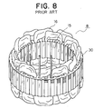
- Figure 8 is an overall perspective of a stator in Figure 6.
- This automotive alternator includes: a case 3 composed of an aluminum front bracket 1 and an aluminum rear bracket 2; a rotating shaft 6 disposed within the case 3 having a pulley 4 secured to a first end thereof; a Lundell-type rotor 7 secured to the rotating shaft 6; fans 5 secured to first and second axial end surfaces of the rotor 7; a stator 8 secured to an inner wall within the case 3; slip rings 9 secured to a second end of the rotating shaft 6 for supplying electric current to the rotor 7; a pair of brushes 10 sliding on surfaces of the slip rings 9; brush holders 11 accommodating the brushes 10; a rectifier 12 electrically connected to the stator 8 for converting alternating current generated in the stator 8 into direct current; and a regulator 18 fitted over the brush holder 11 for adjusting the magnitude of the alternating voltage generated in the stator 8.
- Air intake openings 3a for sucking cooling air into the case 3 and air discharge openings 3b for expelling the cooling air to the outside by rotation of the fans 5 are formed in the case 3.
- the rotor 7 includes a rotor coil 13 for generating magnetic flux on passage of electric current, and a pole core 14 disposed so as to cover the rotor coil 13, magnetic poles being formed in the pole core 14 by the magnetic flux.
- the pole core 14 is constituted by a first pole core body 21 and a second pole core body 22 which intermesh with each other.
- the first pole core body 21 and the second pole core body 22 are made of iron and include tapered first and second claw-shaped magnetic poles 23 and 24.
- the stator 8 is constituted by a stator core 15 for passage of a rotating magnetic field from the rotor 7, and a stator coil 16 constructed by winding wires into the stator core 15, an output current flowing through the stator coil 16.
- the above stator core 15 is constituted by a base portion 30 having notches 48 on an outer circumferential portion, and a plurality of tooth portions 31 which protrude radially inwards from the base portion 30. Slots 32 are formed between adjacent tooth portions 31, and wires are wound continuously into the slots 32.
- FIG 9 is a diagram showing the stator core 15 during manufacture.
- the stator core 15 is manufactured from a straight strip-shaped steel plate 35, which is stamped so as to have a frame portion 37 and a plurality of tooth segments 34 at an even pitch, by laminating and bending the steel plate 35 into a helical shape such that tips of the tooth segments 34 point towards a center.
- the stator core 15 is bent and formed by inserting shaping pins 36 into the slots 32.
- the laminated steel plate 35 which has a thickness of 0.5 mm, is integrated by laser welding at eight places on the outer circumferential portion.
- the cooling air flow generated by the fans 5 is sucked in through the air intake openings 3a formed in the front-end and rear-end brackets 1 and 2, passing in close proximity to and cooling the rectifier 12 and the regulator 18 which are heat-generating portions at a rear end of the alternator, then passes from a radially inner side to a radially outer side between fan blades 5a at both the rear end and a front end, thereby cooling front-end coil ends 16a and rear-end coil ends 16b of the stator coil 16 before being expelled through the air discharge openings 3b.
- the stator coil 16 has three phases, the rotor 7 has twelve magnetic poles, and the slots 32 are formed at a ratio of one per pole per phase, the total number of slots 32 being thirty-six.
- a stator core which is formed with slots at a ratio of two per pole per phase with the aim of providing an automotive alternator in which output voltage is improved and voltage fluctuations are reduced by making an overlapping portion between the claw-shaped magnetic poles of the rotor and the tooth portions of the stator core as small as possible to reduce magnetic flux leakage through the tooth portions and reduce ripples in the rectified output voltage.
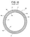
- the total number of slots 41 in a stator core 40 is seventy-two, as shown in Figure 10.
- opening portions 42 of the slots 41 become narrow when the number of the slots 41 in the stator core 40 is seventy-two, it is difficult to continuously wind wires of a stator coil from a radially inner side of the stator core 40 through the opening portions 42.
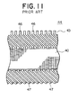
- Figure 11 is a partial front elevation of a stator 44 in which a stator coil 43 has been mounted to the stator core 40 without difficulty using this technical means even though the number of the slots 41 in the stator core 40 is seventy-two.
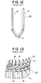
- This stator coil 43 is constituted by a plurality of electrical conductors 45, such as the one shown in Figure 12.
- This electrical conductor 45 is constituted by first and second straight portions 46 and a turn portion 47 connecting the straight portions 46 to each other.
- the first straight portions 46 of the electrical conductors 45 are positioned on a radially inner side being on the opening portion 42 side in a radial direction of first slots 41 to form an inner layer
- the second straight portions 46 of the electrical conductors 45 are positioned on a radially outer side in a radial direction of second slots 41 to form an outer layer.
- the electrical conductors 45 are inserted into the slots 41 from a first end surface of the stator core 40 and are stacked up on top of each other such that the turn portions 47 thereof line up in rows.
- the straight portions 46 on the inner layer and the outer layer which protrude at a second end surface of the slots 41 are bent in a circumferential direction of the stator core 40, and are connected in series to the straight portions 46 in a different layer of the electrical conductors 45 a distance of one pole away, forming the stator coil 43.
- Figure 13 is a partial perspective of an end surface of the stator 44 viewed from the end where the electrical conductors 45 are connected
- Figure 14 is a partial perspective of the end surface of the stator 44 viewed from the end where the electrical conductors 45 are inserted.
- the opening portions 42 of the slots 41 become narrow when the number of slots per pole per phase is two, it is difficult to continuously wind wires of the stator coil from the radially inner side of the stator core 40 through the opening portions 42.
- the electrical conductors 45 are inserted from the first end surface of the slots 41 of the stator core 40, and after protruding from the second end surface of the slots 41, each of the straight portions 46 is bent (twist formation) in the circumferential direction of the stator core 40, and connected in series to the straight portions 46 of the electrical conductors 45 in a different layer a distance of one pole away.
- the stator coil generates heat due to the generated electric current and the temperature rises, causing a reduction in part life.
- the present invention aims to solve the above problems and an object of the present invention is to provide a stator for an automotive alternator which can suppress temperature increases, prevent drops in output, prevent poor pressure resistance, and prevent decreases in output current.
- a stator for an automotive alternator including:
- the core main body may be constructed by laminating the strip-shaped steel plate formed with a plurality of tooth segments at an even pitch while bending the strip-shaped steel plate into a helical shape such that tips of the tooth segments point towards a center.
- the core main body may be constructed by laminating a plurality of the steel plates in an axial direction, the steel plates being annular in shape and being formed with a plurality of tooth segments at an even pitch on an inner circumferential side,
- Each of the tooth portions of the stator may be positioned to form an overlapping portion overlapping two of the first and second claw-shaped magnetic poles on the rotor facing the tooth portion, the two first and second claw-shaped magnetic poles having different polarity and being adjacent in a direction of rotation of the rotor, the end plate being disposed at one end of the overlapping portion thereof.
- the rotor may have centrifugal fans on first and second axial end portions; and coil ends of the stator core of the automotive alternator may be cooled by cooling air which is sucked in through air intake openings and expelled through air discharge openings disposed in the front-end and rear-end brackets.
- the stator coil may be constructed by passing a plurality of generally U-shaped coil segments through the stator core from a first end of the stator core, then forming twists in the generally U-shaped coil segments at the end plate end, and joining together end portions of the generally U-shaped coil segments by welding, the generally U-shaped coil segments being made of copper having a generally flat cross-sectional shape having an insulation coating disposed thereon, the stator coil including:
- a circumferential width dimension of an end plate slot formed in the end plate may be larger than a circumferential width dimension of the core main body slots formed in the core main body.
- a corner portion at an end of the end plate slot formed on the end plate where the generally U-shaped coil segments enter may be eased.
- a resin may be impregnated into a coil end, a greater amount of the resin being impregnated into the coil end at an end surface portion of the stator core than into other portions of the coil end.
- Figure 1 is a cross section of an automotive alternator according to the present invention
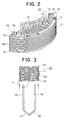
- Figure 2 is a partial perspective of a stator 55 in Figure 1.
- This automotive alternator includes: a case 63 composed of an aluminum front-end bracket 61 and an aluminum rear-end bracket 62; a rotating shaft 6 disposed within the case 63 having a pulley 4 secured to a first end thereof; a Lundell-type rotor 7 secured to the rotating shaft 6; fans 5 secured to first and second axial end surfaces of the rotor 7; a stator 55 secured to an inner wall within the case 63; slip rings 9 secured to a second end of the rotating shaft 6 for supplying electric current to the rotor 7; a pair of brushes 10 sliding on surfaces of the slip rings 9; brush holders 11 accommodating the brushes 10; a rectifier 12 electrically connected to the stator 55 for converting alternating current generated in the stator 55 into direct current; and a regulator 18 fitted over the brush holder 11 for adjusting the magnitude of the alternating voltage generated in the stator 55.
- Air intake openings 63a for sucking cooling air into the case 63 and air discharge openings 63b for expelling the cooling air to the outside by rotation of the fans 5 are formed in the case 63.
- An intermediate portion of a stator core 50 is exposed to the outside.
- the rotor 7 includes a rotor coil 13 for generating magnetic flux on passage of electric current, and a pole core 14 disposed so as to cover the rotor coil 13, magnetic poles being formed in the pole core 14 by the magnetic flux.
- the pole core 14 is constituted by a first pole core body 21 and a second pole core body 22 which intermesh with each other.
- the first pole core body 21 and the second pole core body 22 are made of iron and include tapered first and second claw-shaped magnetic poles 23 and 24.
- the stator 55 is constituted by the stator core 50 for passage of a rotating magnetic field from the rotor 7, and a stator coil 43 which has a plurality of electrical conductors 45 connected and installed in the stator core 50, an output current flowing through the stator coil 43.
- This stator core 50 is constituted by: a core main body 71 constructed by laminating and bending a strip-shaped steel plate 100 into a helical shape such that tips of the tooth segments point towards a center, as is conventionally done, the steel plate 100 being stamped so as to have a plurality of tooth segments at an even pitch; and end plates 70 which sandwich the core main body 71 from a first and second surface.
- the stator core 50 is integrated by securing the steel plate 100 to itself, and the steel plate 100 to the end plates 70, along an axial direction by laser welding at eight places on an outer circumferential surface.
- This stator core 50 is constituted by a base portion 51 having a flat outer circumferential surface, and a plurality of tooth portions 52 which protrude radially inwards from the base portion 51.
- the stator coil 43 has three phases
- the rotor 7 has twelve poles
- the total number of slots 53 in the stator core 50 is seventy-two.
- This stator coil 43 is constituted by a plurality of the electrical conductors 45, such as the one shown in Figure 12.
- This electrical conductor 45 is constituted by first and second straight portions 46 and a turn portion 47 connecting the straight portions 46 to each other.
- the first straight portions 46 of the electrical conductors 45 are positioned on a radially inner side being on an opening portion 42 side in a radial direction of first slots 41 to form an inner layer
- the second straight portions 46 of the electrical conductors 45 are positioned on a radially outer side in a radial direction of second slots 41 to form an outer layer.
- Figure 3 is a diagram explaining the state of the electrical conductor 45 during insertion into the stator core 50 in Figure 2, and Figure 4 is an enlargement of area C in Figure 3.
- stator core 50 because the end plates 70 which are thicker than the steel plates 100 are disposed on end surfaces, rigidity of the stator core 50 can be improved, enabling drops in output to be prevented because misalignment of the core and disruption of the magnetic circuit is eliminated.
- the stator core 50 When the stator core 50 is manufactured by laminating and bending the strip-shaped steel plate 100 into a helical shape, the end portions at a winding start portion and a winding finish portion of the steel plate 100 are not welded in some cases, and a conventional problem in such cases has been that the winding start portion and the winding finish portion are easily peeled away, contacting the stator coil and causing short-circuits, thereby reducing output, but because the end plates 70 are welded onto the end surfaces in the stator core 50 according to the present embodiment, peeling of the steel plates 100 can be completely prevented.
- a circumferential width L1 of an end plate slot 72 of the end plates 70 is wider than a circumferential width L2 of a core main body slot 73 of the core main body 71, and a corner portion of the end of the end plate slots 72 where the electrical conductors 45 enter is eased into an arc-shaped cross section, forming a curved surface portion 74. For that reason, when the straight portions 46 of the electrical conductors 45 are inserted into the slots 53 of the stator core 50, the electrical conductors 45 can be inserted into the slots 53 without damaging an insulation coating on the straight portions 46.
- the cooling air flow generated by the fans 5 is sucked in through the air intake openings 63a formed in the front-end and rear-end brackets 61 and 62, passing in close proximity to and cooling the rectifier 12 and the regulator 18 which are heat-generating portions at a rear end of the alternator, then passes from a radially inner side to a radially outer side between fan blades 5a at both the rear end and a front end, thereby cooling front-end coil ends 43a and rear-end coil ends 43b of the stator coil 43 before being expelled through the air discharge openings 63b.
- the first and second end portions of each of the tooth portions 52 formed in the stator core 50 are formed so as to simultaneously overlap the two first and second claw-shaped magnetic poles 23 and 24 having different polarity and being adjacent in a direction of rotation of the rotor 7 facing the first and second end portions of the tooth portions 52.
- the end plates 70 are positioned on end portions of these overlapping portions.
- magnetic flux which has entered the tooth portions 52 from the claw-shaped magnetic poles constitutes the magnetic circuit by passing through outer radial portions of the core to tooth portions 52 which are a pitch of one magnetic pole away, but due to the construction of the claw-shaped magnetic poles, the magnetic flux passes along a surface of the tooth portions 52 and a certain amount leaks to the adjacent magnetic pole.
- the thick end plates 70 are disposed on the core end surfaces, it is easier for the magnetic flux which has entered the tooth portions 52 from claw roots to pass through an outer side (on an inner portion side) than along the surface of the tooth portions 52. For that reason, the amount of magnetic flux leakage at tip surfaces of the tooth portions 52 is reduced, increasing output current.
- a resin is impregnated into the coil ends 43a and 43b, a greater amount of the resin being impregnated into the coil ends 43a and 43b at end surface portions of the stator core 50 than into other portions of the coil ends 43a and 43b. For that reason, the resin is impregnated between the stator coil 43 and the stator core 50, further improving electrical insulation.
- the core main body 71 is constructed by laminating and bending the strip-shaped steel plate 100 into the helical shape such that the tips of the tooth segments point towards the center, the steel plate 100 being stamped so as to have a plurality of tooth segments at an even pitch, but the core main body is not limited to this example and may also be constructed by laminating a plurality of annular steel plates in an axial direction, the steel plates being formed with a plurality of tooth segments at an even pitch on an inner circumferential side.
- the corner portion of the entrance end of the electrical conductors 45 of the end plate slot 72 is eased into an arc-shaped cross section, forming the curved surface portion 74, but the corner portion of the end plate slot 72 may also be eased into a tapered shape, achieving the same general effect.
- a stator for an automotive alternator including:
- the core main body may be constructed by laminating the strip-shaped steel plate formed with a plurality of tooth segments at an even pitch while bending the strip-shaped steel plate into a helical shape such that tips of the tooth segments point towards a center. For that reason, the problem of peeling away of the steel plate at a winding start portion and a winding finish portion of the steel plate of the core body can be completely prevented.
- the core main body may be constructed by laminating a plurality of the steel plates in an axial direction, the steel plates being annular in shape and being formed with a plurality of tooth segments at an even pitch on an inner circumferential side. For that reason, rigidity of the stator core can be further improved, enabling drops in output to be prevented because misalignment of the core and disruption of the magnetic circuit is eliminated.
- Each of the tooth portions of the stator may be positioned to form an overlapping portion overlapping two of the first and second claw-shaped magnetic poles on the rotor facing the tooth portion, the two first and second claw-shaped magnetic poles having different polarity and being adjacent in a direction of rotation of the rotor, the end plate being disposed at one end of the overlapping portion thereof. For that reason, because the amount of magnetic flux leakage at the tip surfaces of the tooth portions is reduced, output current in the alternator can be increased.
- the rotor may have centrifugal fans on first and second axial end portions; and coil ends of the stator core of the automotive alternator may be cooled by cooling air which is sucked in through air intake openings and expelled through air discharge openings disposed in the front-end and rear-end brackets. For that reason, heat transferred to the end surface of the stator core can be efficiently cooled, further reducing temperature increases in the stator coil.
- the stator coil may be constructed by passing a plurality of generally U-shaped coil segments through the stator core from a first end of the stator core, then forming twists in the generally U-shaped coil segments at the end plate end, and joining together end portions of the generally U-shaped coil segments by welding, the generally U-shaped coil segments being made of copper having a generally flat cross-sectional shape having an insulation coating disposed thereon, the stator coil including:
- a circumferential width dimension of an end plate slot formed in the end plate may be larger than a circumferential width dimension of the core main body slots formed in the core main body. For that reason, scraping off of the insulation coating caused by contact with the stator core when inserting the stator coil and deformation of the coil are reduced, enabling short-circuiting between the stator core and the stator coil to be reduced to a minimum. Furthermore, in the coil end at the twist formation end of the stator coil, the problem of short-circuiting due to scratching of the insulation coating on the stator coil caused by pressure on the coil during twist formation can be reduced.
- a corner portion at an end of the end plate slot formed on the end plate where the generally U-shaped coil segments enter may be eased. For that reason, scraping off of an insulation coating caused by contact with the stator core when inserting the stator coil and deformation of the coil are reduced, enabling short-circuiting between the stator core and the stator coil to be reduced to a minimum. Furthermore, in a coil end at the twist formation end of the stator coil, the problem of short-circuiting due to scratching of the insulation coating on the stator coil caused by pressure on the coil during twist formation can be reduced.
- a resin may be impregnated into a coil end, a greater amount of the resin being impregnated into the coil end at an end surface portion of the stator core than into other portions of the coil end. For that reason, resin is impregnated between the stator coil and the stator core, further improving insulation.
Landscapes
- Engineering & Computer Science (AREA)
- Power Engineering (AREA)
- Manufacturing & Machinery (AREA)
- Synchronous Machinery (AREA)
- Iron Core Of Rotating Electric Machines (AREA)
- Windings For Motors And Generators (AREA)
- Motor Or Generator Cooling System (AREA)
- Insulation, Fastening Of Motor, Generator Windings (AREA)
- Manufacture Of Motors, Generators (AREA)
Abstract
Description
coil ends of the stator core of the automotive alternator may be cooled by cooling air which is sucked in through air intake openings and expelled through air discharge openings disposed in the front-end and rear-end brackets.
the stator coil including:
coil ends of the stator core of the automotive alternator may be cooled by cooling air which is sucked in through air intake openings and expelled through air discharge openings disposed in the front-end and rear-end brackets. For that reason, heat transferred to the end surface of the stator core can be efficiently cooled, further reducing temperature increases in the stator coil.
the stator coil including:
Claims (9)
- A stator for an automotive alternator, said automotive alternator comprising:a rotor (7) having first and second claw-shaped magnetic poles (23, 24) fitted onto a rotating shaft (6); anda stator (55) having a stator core (50) supported between front-end and rear-end brackets (61, 62), a stator coil (43) which is connected into a three-phase alternating current connection being wound into said stator core (50),said stator core (50) comprising:a core main body (71) constructed by laminating a strip-shaped steel plate (100), said core main body (71) comprising a base portion (51) and a plurality of tooth portions (52) protruding radially inwards from said base portion (51) defining core main body slots (53); andan end plate (70) which is thicker than said steel plate (100) being disposed on at least one end surface of said core main body (71).
- The stator for an automotive alternator according to Claim 1 wherein said core main body (71) is constructed by laminating said strip-shaped steel plate (100) formed with a plurality of tooth segments at an even pitch while bending said strip-shaped steel plate (100) into a helical shape such that tips of said tooth segments point towards a center.
- The stator for an automotive alternator according to Claim 1 wherein said core main body (71) is constructed by laminating a plurality of said steel plates (100) in an axial direction, said steel plates (100) being annular in shape and being formed with a plurality of tooth segments at an even pitch on an inner circumferential side.
- The stator for an automotive alternator according to any of Claims 1 to 3 wherein each of said tooth portions (52) of said stator (55) is positioned to form an overlapping portion overlapping two of said first and second claw-shaped magnetic poles (23, 24) on said rotor (7) facing said tooth portion (52), said two first and second claw-shaped magnetic poles (23, 24) having different polarity and being adjacent in a direction of rotation of said rotor (7), said end plate (70) being disposed at one end of said overlapping portion thereof.
- The stator for an automotive alternator according to any of Claims 1 to 4 wherein:said rotor (7) has centrifugal fans (5) on first and second axial end portions; andcoil ends of said stator core (50) of said automotive alternator are cooled by cooling air which is sucked in through air intake openings (63a) and expelled through air discharge openings (63b) disposed in said front-end and rear-end brackets (61, 62).
- The stator for an automotive alternator according to any of Claims 1 to 5 wherein said stator coil (43) is constructed by passing a plurality of generally U-shaped coil segments (45) through said stator core (50) from a first end of said stator core (50), then forming twists in said generally U-shaped coil segments (45) at said end plate (70) end, and joining together end portions of said generally U-shaped coil segments (45) by welding, said generally U-shaped coil segments (45) being made of copper having a generally flat cross-sectional shape having an insulation coating disposed thereon,
said stator coil (43) comprising:a pair of conductors (46) disposed in a straight line in a radial direction in each of said core main body slots (53);insulating paper for electrically insulating said coil segments (45) from said stator core (50); anda joint portion joining an inner-layer-side coil segment end and an outer-layer-side coil segment end. - The stator for an automotive alternator according to any of Claims 1 to 6 wherein a circumferential width dimension of an end plate slot (72) formed in said end plate (70) is larger than a circumferential width dimension of said core main body slots (53) formed in said core main body (71).
- The stator for an automotive alternator according to Claim 6 wherein a corner portion at an end of said end plate slot (72) formed on said end plate (70) where said generally U-shaped coil segments (45) enter is eased.
- The stator for an automotive alternator according to any of Claims 1 to 8 wherein a resin is impregnated into a coil end, a greater amount of said resin being impregnated into said coil end at an end surface portion of said stator core (50) than into other portions of said coil end.
Applications Claiming Priority (2)
| Application Number | Priority Date | Filing Date | Title |
|---|---|---|---|
| JP2000089008A JP2001275283A (en) | 2000-03-28 | 2000-03-28 | Stator of vehicle alternator |
| JP2000089008 | 2000-03-28 |
Publications (3)
| Publication Number | Publication Date |
|---|---|
| EP1139541A2 true EP1139541A2 (en) | 2001-10-04 |
| EP1139541A3 EP1139541A3 (en) | 2002-11-06 |
| EP1139541B1 EP1139541B1 (en) | 2005-03-09 |
Family
ID=18604814
Family Applications (1)
| Application Number | Title | Priority Date | Filing Date |
|---|---|---|---|
| EP00125271A Expired - Lifetime EP1139541B1 (en) | 2000-03-28 | 2000-11-24 | Stator for an automotive alternator |
Country Status (5)
| Country | Link |
|---|---|
| US (1) | US6566781B2 (en) |
| EP (1) | EP1139541B1 (en) |
| JP (1) | JP2001275283A (en) |
| KR (1) | KR100419131B1 (en) |
| DE (1) | DE60018550T2 (en) |
Cited By (2)
| Publication number | Priority date | Publication date | Assignee | Title |
|---|---|---|---|---|
| FR2839826A1 (en) * | 2002-05-16 | 2003-11-21 | Mitsubishi Electric Corp | METHOD FOR MANUFACTURING A STATOR CORE FOR A DYNAMO-ELECTRIC MACHINE |
| CN113890236A (en) * | 2020-07-02 | 2022-01-04 | 保时捷股份公司 | Stator for an electric machine, motor vehicle, method for producing a stator |
Families Citing this family (22)
| Publication number | Priority date | Publication date | Assignee | Title |
|---|---|---|---|---|
| JP3551378B2 (en) | 2001-12-26 | 2004-08-04 | 株式会社デンソー | Coil of rotating electric machine and method of manufacturing the same |
| DE10245691A1 (en) * | 2002-09-30 | 2004-04-08 | Robert Bosch Gmbh | Stand for an electrical machine |
| KR100474922B1 (en) * | 2002-12-12 | 2005-03-10 | 엘지전자 주식회사 | Motor |
| JP2004282858A (en) * | 2003-03-14 | 2004-10-07 | Hitachi Ltd | Stator and rotating machine using the same |
| US20050174006A1 (en) * | 2004-02-06 | 2005-08-11 | Valeo Electrical Systems, Inc. | Winding topologies for stators in brushless motors |
| KR20050099352A (en) * | 2004-04-09 | 2005-10-13 | 엘지전자 주식회사 | Front suction/discharge type outdoor unit for air conditioner |
| JP4501762B2 (en) * | 2005-04-18 | 2010-07-14 | 株式会社デンソー | Vehicle alternator |
| JP2006345671A (en) * | 2005-06-10 | 2006-12-21 | Denso Corp | Rotating electric machine for vehicles |
| JP2007037280A (en) * | 2005-07-27 | 2007-02-08 | Mitsubishi Electric Corp | Inverter-integrated rotating electrical machine |
| EP2045896B1 (en) * | 2006-07-26 | 2019-09-04 | Mitsubishi Electric Corporation | Dynamo-electric machine |
| GB2442507B (en) * | 2006-10-04 | 2011-05-11 | Converteam Ltd | Stators for electrical machines |
| JP4607964B2 (en) * | 2007-02-26 | 2011-01-05 | 三菱電機株式会社 | Electric motor stator, electric motor, pump, and electric motor manufacturing method |
| JP4447619B2 (en) * | 2007-03-20 | 2010-04-07 | 株式会社日本自動車部品総合研究所 | Laminated iron core |
| DE102009044945A1 (en) * | 2009-09-24 | 2011-03-31 | Robert Bosch Gmbh | Pole-changing electrical machine |
| JP5516068B2 (en) * | 2010-05-24 | 2014-06-11 | 株式会社デンソー | Rotating electric machine |
| DE102012002087B4 (en) * | 2012-02-06 | 2020-03-12 | Sew-Eurodrive Gmbh & Co Kg | Device with laminated core and receiving part |
| JP5729368B2 (en) * | 2012-10-31 | 2015-06-03 | トヨタ自動車株式会社 | Segment coil manufacturing method |
| US20140210300A1 (en) * | 2013-01-30 | 2014-07-31 | Victory Industrial Corporation | Stator of an Alternator |
| US20140210301A1 (en) * | 2013-01-30 | 2014-07-31 | Victory Industrial Corporation | Stator of an Alternator |
| US9214845B2 (en) | 2013-03-11 | 2015-12-15 | Tempel Steel Company | Process for annealing of helical wound cores used for automotive alternator applications |
| US10985633B2 (en) * | 2014-06-10 | 2021-04-20 | The Regents Of The University Of Michigan | Vibrational energy harvester with amplifier having gear assembly |
| KR102277482B1 (en) * | 2014-11-03 | 2021-07-14 | 현대모비스 주식회사 | Apparatus of hairpin winding motor using stator plate and method of construction thereof |
Family Cites Families (15)
| Publication number | Priority date | Publication date | Assignee | Title |
|---|---|---|---|---|
| US995A (en) * | 1838-11-03 | Lansing b | ||
| US1919995A (en) * | 1932-10-26 | 1933-07-25 | Gen Electric | Method of forming cores for dynamo-electric machines |
| JPS5843150A (en) * | 1981-09-08 | 1983-03-12 | Fanuc Ltd | Stator |
| JPS59185942U (en) * | 1983-05-26 | 1984-12-10 | 三菱電機株式会社 | electric motor stator core |
| JPS6162334A (en) * | 1984-08-30 | 1986-03-31 | Mitsubishi Electric Corp | rotating electric machine |
| JP3041884B2 (en) * | 1990-05-17 | 2000-05-15 | 株式会社デンソー | AC generator for vehicles |
| JPH0614507A (en) * | 1992-06-29 | 1994-01-21 | Matsushita Electric Ind Co Ltd | Cage rotor |
| JPH06169556A (en) * | 1992-11-30 | 1994-06-14 | Matsushita Electric Ind Co Ltd | Method of manufacturing stator of electric motor and stator core thereof |
| TW288204B (en) * | 1993-12-09 | 1996-10-11 | At & T Corp | |
| FR2733642B1 (en) * | 1995-04-26 | 1997-06-06 | Valeo Equip Electr Moteur | ALTERNATOR FOR A MOTOR VEHICLE PROVIDED WITH EXTERNAL PARTITIONING MEANS TO AVOID A BLOCKING OF THE COOLING AIR CIRCUIT |
| JPH09285087A (en) * | 1996-04-17 | 1997-10-31 | Toshiba Mach Co Ltd | Rotor for reluctance synchronous motor and manufacturing method thereof |
| DE69820534T2 (en) * | 1997-05-14 | 2004-09-23 | Toyota Jidosha K.K., Toyota | Stator for an electric motor |
| US5965965A (en) * | 1997-05-26 | 1999-10-12 | Denso Corporation | Stator winding arrangement of alternator for vehicle |
| JP3744184B2 (en) | 1997-05-26 | 2006-02-08 | 株式会社デンソー | AC generator for vehicles |
| JPH10336925A (en) * | 1997-05-27 | 1998-12-18 | Toshiba Corp | Core of rotating electric machine |
-
2000
- 2000-03-28 JP JP2000089008A patent/JP2001275283A/en active Pending
- 2000-11-24 DE DE60018550T patent/DE60018550T2/en not_active Expired - Lifetime
- 2000-11-24 EP EP00125271A patent/EP1139541B1/en not_active Expired - Lifetime
- 2000-11-30 US US09/725,868 patent/US6566781B2/en not_active Expired - Lifetime
-
2001
- 2001-01-20 KR KR10-2001-0003435A patent/KR100419131B1/en not_active Expired - Lifetime
Cited By (6)
| Publication number | Priority date | Publication date | Assignee | Title |
|---|---|---|---|---|
| FR2839826A1 (en) * | 2002-05-16 | 2003-11-21 | Mitsubishi Electric Corp | METHOD FOR MANUFACTURING A STATOR CORE FOR A DYNAMO-ELECTRIC MACHINE |
| US7260881B2 (en) | 2002-05-16 | 2007-08-28 | Mitsubishi Denki Kabushiki Kaisha | Method for manufacturing a stator core for a dynamoelectric machine |
| US7260880B2 (en) | 2002-05-16 | 2007-08-28 | Mitsubishi Denki Kabushiki Kaisha | Method for manufacturing a stator core for a dynamoelectric machine |
| DE10321221B4 (en) * | 2002-05-16 | 2013-04-11 | Mitsubishi Denki K.K. | Manufacturing method of a stator core for a dynamoelectric machine |
| CN113890236A (en) * | 2020-07-02 | 2022-01-04 | 保时捷股份公司 | Stator for an electric machine, motor vehicle, method for producing a stator |
| CN113890236B (en) * | 2020-07-02 | 2024-12-10 | 保时捷股份公司 | Stator for an electric machine, electric machine, motor vehicle, method for producing a stator |
Also Published As
| Publication number | Publication date |
|---|---|
| JP2001275283A (en) | 2001-10-05 |
| KR20010093641A (en) | 2001-10-29 |
| DE60018550D1 (en) | 2005-04-14 |
| US20020047483A1 (en) | 2002-04-25 |
| KR100419131B1 (en) | 2004-02-18 |
| DE60018550T2 (en) | 2006-02-16 |
| EP1139541A3 (en) | 2002-11-06 |
| EP1139541B1 (en) | 2005-03-09 |
| US6566781B2 (en) | 2003-05-20 |
Similar Documents
| Publication | Publication Date | Title |
|---|---|---|
| EP1139541B1 (en) | Stator for an automotive alternator | |
| US6268678B1 (en) | Alternator | |
| US6501205B1 (en) | Alternator | |
| US6396185B1 (en) | Alternator | |
| EP1107425B1 (en) | Vehicular AC generator | |
| US6326715B1 (en) | Stator for an automotive alternator | |
| JP3265967B2 (en) | Alternator | |
| US6501204B1 (en) | Stator for an alternator | |
| US6455972B1 (en) | Alternator | |
| US6690099B2 (en) | Automotive alternator | |
| US20140354095A1 (en) | Rotating Electrical Machine | |
| US6366000B1 (en) | Alternator | |
| US6717316B2 (en) | Alternator and method of manufacture therefor | |
| JP2000166149A (en) | Stator of vehicle alternator | |
| US6424071B1 (en) | Automotive alternator | |
| JP2002044890A (en) | Rotating electric machine | |
| EP1109292B1 (en) | Stator windings of an alternator | |
| US8143758B2 (en) | Winding bobbin and rotating electric machine | |
| CN100479296C (en) | AC generator for vehicle | |
| EP2113992B1 (en) | Ac generator | |
| US6441526B1 (en) | Alternator | |
| CN100365917C (en) | alternator | |
| JP2001231194A (en) | Alternator | |
| JP2002051490A (en) | AC generator for vehicles | |
| EP1109295B1 (en) | Winding heads for the stator of an alternator |
Legal Events
| Date | Code | Title | Description |
|---|---|---|---|
| PUAI | Public reference made under article 153(3) epc to a published international application that has entered the european phase |
Free format text: ORIGINAL CODE: 0009012 |
|
| AK | Designated contracting states |
Kind code of ref document: A2 Designated state(s): AT BE CH CY DE DK ES FI FR GB GR IE IT LI LU MC NL PT SE TR |
|
| AX | Request for extension of the european patent |
Free format text: AL;LT;LV;MK;RO;SI |
|
| PUAL | Search report despatched |
Free format text: ORIGINAL CODE: 0009013 |
|
| AK | Designated contracting states |
Kind code of ref document: A3 Designated state(s): AT BE CH CY DE DK ES FI FR GB GR IE IT LI LU MC NL PT SE TR |
|
| AX | Request for extension of the european patent |
Free format text: AL;LT;LV;MK;RO;SI |
|
| 17P | Request for examination filed |
Effective date: 20021118 |
|
| AKX | Designation fees paid |
Designated state(s): DE FR GB |
|
| 17Q | First examination report despatched |
Effective date: 20030912 |
|
| GRAP | Despatch of communication of intention to grant a patent |
Free format text: ORIGINAL CODE: EPIDOSNIGR1 |
|
| GRAS | Grant fee paid |
Free format text: ORIGINAL CODE: EPIDOSNIGR3 |
|
| GRAA | (expected) grant |
Free format text: ORIGINAL CODE: 0009210 |
|
| AK | Designated contracting states |
Kind code of ref document: B1 Designated state(s): DE FR GB |
|
| REG | Reference to a national code |
Ref country code: GB Ref legal event code: FG4D |
|
| REG | Reference to a national code |
Ref country code: IE Ref legal event code: FG4D |
|
| REF | Corresponds to: |
Ref document number: 60018550 Country of ref document: DE Date of ref document: 20050414 Kind code of ref document: P |
|
| REG | Reference to a national code |
Ref country code: GB Ref legal event code: 727 |
|
| REG | Reference to a national code |
Ref country code: GB Ref legal event code: 727A |
|
| PLBE | No opposition filed within time limit |
Free format text: ORIGINAL CODE: 0009261 |
|
| STAA | Information on the status of an ep patent application or granted ep patent |
Free format text: STATUS: NO OPPOSITION FILED WITHIN TIME LIMIT |
|
| ET | Fr: translation filed | ||
| 26N | No opposition filed |
Effective date: 20051212 |
|
| REG | Reference to a national code |
Ref country code: GB Ref legal event code: 727B |
|
| REG | Reference to a national code |
Ref country code: FR Ref legal event code: PLFP Year of fee payment: 16 |
|
| REG | Reference to a national code |
Ref country code: FR Ref legal event code: PLFP Year of fee payment: 17 |
|
| REG | Reference to a national code |
Ref country code: FR Ref legal event code: PLFP Year of fee payment: 18 |
|
| PGFP | Annual fee paid to national office [announced via postgrant information from national office to epo] |
Ref country code: GB Payment date: 20171122 Year of fee payment: 18 |
|
| REG | Reference to a national code |
Ref country code: FR Ref legal event code: PLFP Year of fee payment: 19 |
|
| GBPC | Gb: european patent ceased through non-payment of renewal fee |
Effective date: 20181124 |
|
| PG25 | Lapsed in a contracting state [announced via postgrant information from national office to epo] |
Ref country code: GB Free format text: LAPSE BECAUSE OF NON-PAYMENT OF DUE FEES Effective date: 20181124 |
|
| PGFP | Annual fee paid to national office [announced via postgrant information from national office to epo] |
Ref country code: DE Payment date: 20191112 Year of fee payment: 20 |
|
| PGFP | Annual fee paid to national office [announced via postgrant information from national office to epo] |
Ref country code: FR Payment date: 20191015 Year of fee payment: 20 |
|
| REG | Reference to a national code |
Ref country code: DE Ref legal event code: R071 Ref document number: 60018550 Country of ref document: DE |