EP1139477A1 - Sealed cylindrical nickel-hydrogen storage battery - Google Patents
Sealed cylindrical nickel-hydrogen storage battery Download PDFInfo
- Publication number
- EP1139477A1 EP1139477A1 EP00909750A EP00909750A EP1139477A1 EP 1139477 A1 EP1139477 A1 EP 1139477A1 EP 00909750 A EP00909750 A EP 00909750A EP 00909750 A EP00909750 A EP 00909750A EP 1139477 A1 EP1139477 A1 EP 1139477A1
- Authority
- EP
- European Patent Office
- Prior art keywords
- electrode
- polarity
- separator
- electrodes
- storage battery
- Prior art date
- Legal status (The legal status is an assumption and is not a legal conclusion. Google has not performed a legal analysis and makes no representation as to the accuracy of the status listed.)
- Granted
Links
Images


Classifications
-
- H—ELECTRICITY
- H01—ELECTRIC ELEMENTS
- H01M—PROCESSES OR MEANS, e.g. BATTERIES, FOR THE DIRECT CONVERSION OF CHEMICAL ENERGY INTO ELECTRICAL ENERGY
- H01M10/00—Secondary cells; Manufacture thereof
- H01M10/34—Gastight accumulators
- H01M10/345—Gastight metal hydride accumulators
-
- H—ELECTRICITY
- H01—ELECTRIC ELEMENTS
- H01M—PROCESSES OR MEANS, e.g. BATTERIES, FOR THE DIRECT CONVERSION OF CHEMICAL ENERGY INTO ELECTRICAL ENERGY
- H01M10/00—Secondary cells; Manufacture thereof
- H01M10/24—Alkaline accumulators
- H01M10/28—Construction or manufacture
- H01M10/283—Cells or batteries with two cup-shaped or cylindrical collectors
-
- H—ELECTRICITY
- H01—ELECTRIC ELEMENTS
- H01M—PROCESSES OR MEANS, e.g. BATTERIES, FOR THE DIRECT CONVERSION OF CHEMICAL ENERGY INTO ELECTRICAL ENERGY
- H01M4/00—Electrodes
- H01M4/02—Electrodes composed of, or comprising, active material
- H01M2004/025—Electrodes composed of, or comprising, active material with shapes other than plane or cylindrical
-
- H—ELECTRICITY
- H01—ELECTRIC ELEMENTS
- H01M—PROCESSES OR MEANS, e.g. BATTERIES, FOR THE DIRECT CONVERSION OF CHEMICAL ENERGY INTO ELECTRICAL ENERGY
- H01M6/00—Primary cells; Manufacture thereof
- H01M6/04—Cells with aqueous electrolyte
- H01M6/06—Dry cells, i.e. cells wherein the electrolyte is rendered non-fluid
- H01M6/10—Dry cells, i.e. cells wherein the electrolyte is rendered non-fluid with wound or folded electrodes
-
- H—ELECTRICITY
- H01—ELECTRIC ELEMENTS
- H01M—PROCESSES OR MEANS, e.g. BATTERIES, FOR THE DIRECT CONVERSION OF CHEMICAL ENERGY INTO ELECTRICAL ENERGY
- H01M6/00—Primary cells; Manufacture thereof
- H01M6/42—Grouping of primary cells into batteries
-
- Y—GENERAL TAGGING OF NEW TECHNOLOGICAL DEVELOPMENTS; GENERAL TAGGING OF CROSS-SECTIONAL TECHNOLOGIES SPANNING OVER SEVERAL SECTIONS OF THE IPC; TECHNICAL SUBJECTS COVERED BY FORMER USPC CROSS-REFERENCE ART COLLECTIONS [XRACs] AND DIGESTS
- Y02—TECHNOLOGIES OR APPLICATIONS FOR MITIGATION OR ADAPTATION AGAINST CLIMATE CHANGE
- Y02E—REDUCTION OF GREENHOUSE GAS [GHG] EMISSIONS, RELATED TO ENERGY GENERATION, TRANSMISSION OR DISTRIBUTION
- Y02E60/00—Enabling technologies; Technologies with a potential or indirect contribution to GHG emissions mitigation
- Y02E60/10—Energy storage using batteries
-
- Y—GENERAL TAGGING OF NEW TECHNOLOGICAL DEVELOPMENTS; GENERAL TAGGING OF CROSS-SECTIONAL TECHNOLOGIES SPANNING OVER SEVERAL SECTIONS OF THE IPC; TECHNICAL SUBJECTS COVERED BY FORMER USPC CROSS-REFERENCE ART COLLECTIONS [XRACs] AND DIGESTS
- Y02—TECHNOLOGIES OR APPLICATIONS FOR MITIGATION OR ADAPTATION AGAINST CLIMATE CHANGE
- Y02P—CLIMATE CHANGE MITIGATION TECHNOLOGIES IN THE PRODUCTION OR PROCESSING OF GOODS
- Y02P70/00—Climate change mitigation technologies in the production process for final industrial or consumer products
- Y02P70/50—Manufacturing or production processes characterised by the final manufactured product
-
- Y—GENERAL TAGGING OF NEW TECHNOLOGICAL DEVELOPMENTS; GENERAL TAGGING OF CROSS-SECTIONAL TECHNOLOGIES SPANNING OVER SEVERAL SECTIONS OF THE IPC; TECHNICAL SUBJECTS COVERED BY FORMER USPC CROSS-REFERENCE ART COLLECTIONS [XRACs] AND DIGESTS
- Y10—TECHNICAL SUBJECTS COVERED BY FORMER USPC
- Y10T—TECHNICAL SUBJECTS COVERED BY FORMER US CLASSIFICATION
- Y10T29/00—Metal working
- Y10T29/49—Method of mechanical manufacture
- Y10T29/49002—Electrical device making
- Y10T29/49108—Electric battery cell making
Definitions
- the present invention relates to an improvement of small-sized, high-capacity nickel-metal hydride storage batteries composed of a nickel positive electrode, a hydrogen storage alloy negative electrode, a separator and an alkaline electrolyte.
- a nickel-metal hydride storage battery is a secondary battery comprising a positive electrode formed from an active material composed mainly of nickel hydroxide and a negative electrode composed mainly of a hydrogen storage alloy, and has been widely used as a power source of portable equipment.
- an increase in the capacity has been desired for the further spread thereof.
- an electrode group inserted into a metal case generally has a so-called spiral structure in which a positive electrode plate, a negative electrode plate and a separator for separating these electrode plates from each other are wound in a spiral form.
- the electrode group with this spiral structure has such problems that a large amount of the separator which does not contribute to the battery capacity is present at the beginning of the winding and at the end of the winding, and a useless volume portion is present at the end of the winding because of its non-concentric form.
- Japanese Laid-Open Utility Model Publication (Jitsukaisho) No. 58-24967 proposes an alkaline storage battery formed by combining a cylindrical sintered-type electrode and a columnar sintered-type electrode. This makes it possible to easily insert the electrode group into a metal case.
- the electrodes use a porous sintered nickel substrate with a porosity of about 80% obtained by sintering a nickel powder, the porosity of the substrate can not be increased any more, and thus the filling efficiency of an active material is low and an increase in the capacity is limited.
- a battery formed by layering a columnar electrode of one polarity and a hollow cylindrical electrode of the other polarity in the form of concentric circles with a separator interposed therebetween so that the columnar electrode is located in the center; and a nickel-metal hydride storage battery formed by layering, round a columnar electrode of one polarity, a separator, a hollow cylindrical electrode of the other polarity, a separator and a hollow cylindrical electrode of the one polarity in this order.
- the first problem is a characteristic problem that an actual battery capacity at a specific high-current discharge is much lower than that of batteries with a conventional structure because the area of the mutually facing electrodes is small.
- the second problem is a productive problem that, in a state in which the electrode group is being inserted in the metal case, it takes a long time to inject an electrolyte.
- the present invention ensures a certain area or more area of facing positive and negative electrodes by an electrode group structure in which electrodes of different polarities are repeatedly layered in the form of concentric circles with a separator interposed therebetween, and thereby solving the above-mentioned first problem.
- the present invention forms an electrode serving as the center of an electrode group in a hollow cylindrical shape to facilitate the injection of an electrolyte into the hollow section, or layered electrodes in many layers to facilitate the injection of an electrolyte into a separator between the electrodes, and thereby solving the second problem.
- the present invention provides a sealed cylindrical nickel-metal hydride storage battery comprising: an electrode group; a metal case for accommodating the electrode group; and a seal plate provided with a safety vent, for sealing an opening of the metal case, the electrode group being composed of at least one non-sintered type hollow cylindrical electrode of one polarity, at least one non-sintered type hollow cylindrical electrode of the other polarity and a separator for separating these electrodes from each other, wherein the electrodes are arranged alternately in the form of concentric circles with a separator interposed therebetween so that the electrode of the one polarity is located in the center.
- the present invention provides a sealed cylindrical nickel-metal hydride storage battery comprising: an electrode group; a metal case for accommodating the electrode group; and a seal plate provided with a safety vent, for sealing an opening of the metal case, the electrode group being composed of a non-sintered type columnar electrode of one polarity, at least one non-sintered type hollow cylindrical electrode of the one polarity, at least two non-sintered type hollow cylindrical electrodes of the other polarity and a separator for separating these electrodes from each other, wherein the cylindrical electrode of the other polarity and the cylindrical electrode of the one polarity are arranged alternately in the form of concentric circles with the separator interposed therebetween so that the columnar electrode of the one polarity is located in the center.
- the present invention is directed to a sealed cylindrical nickel-metal hydride storage battery comprising: an electrode group; a metal case for accommodating the electrode group; and a seal plate provided with a safety vent, for sealing an opening of the metal case, and characterized in that the electrode group is composed of at least one non-sintered type hollow cylindrical electrode of one polarity, at least one non-sintered type hollow cylindrical electrode of the other polarity and a separator for separating these electrodes from each other and that the electrodes are arranged alternately in the form of concentric circles with the separator interposed therebetween so that the electrode of the one polarity is located in the center.
- the present invention is characterized in that the electrode group is composed of a non-sintered type columnar electrode of one polarity, at least one non-sintered type hollow cylindrical electrode of the one polarity, at least two non-sintered type hollow cylindrical electrodes of the other polarity and a separator for separating these electrodes from each other and that the cylindrical electrode of the other polarity and the cylindrical electrode of the one polarity are arranged alternately in the form of concentric circles with the separator interposed therebetween so that the columnar electrode of the one polarity is located in the center.
- the electrodes of different polarities are repeatedly layered in the form of concentric circles with the separator interposed therebetween, it is possible to ensure a certain area or more area of facing positive and negative electrodes and provide a battery having a sufficient capacity at high-current discharge.
- the electrodes are layered in many layers, it is possible to easily inject an electrolyte into the separator between the electrodes.
- the electrode serving as the center of the electrode group has a hollow cylindrical shape, it is possible to easily inject an electrolyte into the hollow section of the electrode.
- the electrodes are constructed in a configuration comprising vertically split bodies or a slit in a vertical direction, one piece of continuing separator separates the electrode of one polarity from the electrode of the other polarity, and the separator which covers the outer side of the inner electrode only one turn goes through the clearance between the split bodies or the slit of the outer electrode and is connected to its portion covering the outer side of the outer electrode.
- an electrode group comprising hollow cylindrical electrodes of different polarities which are layered alternately with a separator interposed therebetween, when inserting into the hollow section of the electrode of one polarity the electrode of the other polarity with the separator interposed therebetween, such a problem that the separator is caught in the electrode may occur. According to the above-described preferred embodiment, it is possible to prevent the separator from being caught.
- a preferred method for constructing such an electrode group comprises the steps of:
- the electrodes for use in the present invention are preferably electrodes produced by pressure-molding a powder composed mainly of an active material, or by applying or filling the powder to a two-dimensional or three-dimensional metal core and subjecting it to pressure molding
- columnar or hollow cylindrical electrodes are split bodies thereof before a battery is constructed, and the split bodies are assembled into a columnar shape or a hollow cylindrical shape so that the electrodes having the same polarity are electrically connected to each other after the battery is constructed.
- the split bodies of the columnar or hollow cylindrical electrode may be constructed by vertically split electrode bodies, or electrodes bodies cut in round slices.
- the hollow cylindrical electrode may be constructed by an electrode body prepared by bending a sheet-like electrode plate into a cylindrical shape, or an electrode body prepared by winding an electrode plate in a spiral form.
- the hollow cylindrical electrode may be constructed by an electrode body prepared by bending two or more pieces of layered sheet-like electrode plates of the same polarity into a cylindrical shape, or an electrode body prepared by winding two or more pieces of layered electrode plates of the same polarity in a spiral form.
- the electrodes of the same polarity are electrically connected to each other with a metal lead or metal piece (current collector).
- the separator for separating the electrodes of different polarities it is suitable to use a separator obtained by thermally welding a band-like separator at the time it was wound one turn in a cylindrical shape. With the use of this separator, it is possible to construct an extremely concentric electrode group, thereby further improving the efficiency of inserting the electrode group into a metal case.
- the structure of the electrode group has been mainly illustrated.
- the seal plate for sealing the opening of the battery case etc.
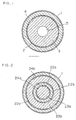
- a paste was prepared by adding 10% by weight of cobalt hydroxide powder to nickel hydroxide powder and adding a predetermined amount of pure water thereto. This paste was applied and filled into a foamed metal of a metal core having a three-dimensionally communicating pore, dried, and then subjected to pressure molding so as to form a hollow cylindrical positive electrode 3 with an internal diameter of about 2 mm and an electrode thickness of about 2.05 mm. Meanwhile, a paste composed mainly of a hydrogen storage alloy was applied to a two-dimensional metal core, dried, and then subjected to pressure molding so as to form a hollow cylindrical negative electrode 4 with an internal diameter of about 6.34 mm and an electrode thickness of about 0.78 mm.
- a separator 2 was prepared by winding a band-like separator sheet one turn to form a cylindrical shape and thermally welding its ends together. Then, as shown in FIG. 1, the hollow cylindrical negative electrode 4 is arranged round the outside of the hollow cylindrical positive electrode 3 with the separator 2 therebetween so as to construct an electrode group. This electrode group is inserted into a metal case 1 of AAAA size and, after injecting an electrolyte, an opening of the case 1 is sealed by a seal plate provided with a safety vent. 5 is a hole constituting a hollow section of the positive electrode 3.
- the positive electrode and the negative electrode are electrically connected to the seal plate and the case, respectively, and a gasket is placed between the seal plate and the case to insulate them electrically so as to assemble a battery having a known structure.
- This battery is denoted as battery A.
- a columnar positive electrode 23a with a diameter of about 2.54 mm, a hollow cylindrical positive electrode 23b with an internal diameter of about 4.06 mm and an electrode thickness of about 1.27 mm, a hollow cylindrical negative electrode 24a with an internal diameter of about 2.78 mm and an electrode thickness of about 0.52 mm, and a hollow cylindrical negative electrode 24b with an internal diameter of about 6.84 mm and an electrode thickness of about 0.52 mm were formed.
- the columnar positive electrode 23a and hollow cylindrical positive electrode 23b had a structure having a section which was composed only of a metal core and was not filled with an active material at their upper part, while the hollow cylindrical negative electrodes 24a and 24b had a structure having a section which was composed only of a metal core and was not filled with the active material at their lower part.
- an electrode group was fabricated by arranging the columnar positive electrode 23a, separator 22a, hollow cylindrical negative electrode 24a, separator 22b, hollow cylindrical positive electrode 23b, separator 22c and hollow cylindrical negative electrode 24b in this order in the form of concentric circles so that the columnar positive electrode 23a was located in the center.
- the metal core sections of the positive electrodes 23a and 23b were electrically connected to each other in the upper part of the electrode group and the metal core sections of the negative electrodes 24a and 24b were electrically connected to each other in the lower part of the electrode group, respectively, by welding using a disk-shaped metal piece.
- This electrode group was inserted into the metal case 1 of AAAA size and, after injecting an electrolyte, the opening of the case 1 was sealed by the seal plate electrically connected to the positive electrode so as to assemble a battery B.
- the cylindrical positive electrode 33a and hollow cylindrical positive electrode 33b had a structure having a metal core section which was not filled with the active material at their upper part, while the hollow cylindrical negative electrodes 34a and 34b had a structure having a metal core section which was not filled with the active material at their lower part.
- An electrode group was fabricated by arranging the hollow cylindrical positive electrode 33a, separator 32a, hollow cylindrical negative electrode 34a, separator 32b, hollow cylindrical positive electrode 33b, separator 32c and hollow cylindrical negative electrode 34b in this order in the form of concentric circles so that the hollow cylindrical positive electrode 33a was located in the center.
- the metal core sections of the positive electrodes 33a and 33b were electrically connected to each other in the upper part of the electrode group and the metal core sections of the negative electrodes 34a and 34b were electrically connected to each other in the lower part of the electrode group, respectively, by welding using a disk-shaped metal piece.
- This electrode group was inserted into the metal case 1 of AAAA size and, after injecting an electrolyte, the opening of the case 1 was sealed by the seal plate electrically connected to the positive electrode so as to assemble a battery C.
- a battery D was fabricated by arranging, as shown in FIG. 6, a columnar positive electrode 53 with a diameter of 5.97 mm, a separator 52 and a hollow cylindrical negative electrode 54 with an internal diameter of 6.21 mm and a thickness of 0.84 mm in this order in the form of concentric circles so that the columnar positive electrode 53 was located in the center.
- a battery E was fabricated by arranging, as shown in FIG. 7, a columnar negative electrode 64a with a diameter of 1.48 mm, a separator 62a, a hollow cylindrical positive electrode 63 with an internal diameter of 1.72 mm and a thickness of 2.22 mm, a separator 62b, and a hollow cylindrical negative electrode 64b with an internal diameter of 6.56 mm and a thickness of 0.67 mm in this order in the form of concentric circles so that the columnar negative electrode 64a was located in the center.
- a battery F was fabricated by winding a positive electrode plate 73, a negative electrode plate 74 and a separator 72 for separating these electrode plates from each other in a spiral form.
- This battery has spaces 75a and 75b at the beginning of winding and the end of the winding of the electrode group.
- the theoretical capacity of the negative electrode was made 1.5 times the theoretical capacity of the positive electrode, a non-woven polypropylene fabric to which a hydrophilic property was imparted was used as the separator, and a solution prepared by adding 40 g/l of lithium monohydrate to 7M of KOH aqueous solution was used as the electrolyte.
- the electrolyte was injected in a constant amount of 95% of the spatial volume inside the electrode group.
- the injection of the electrolyte was performed under the same conditions using a centrifugal injecting machine that injects the electrolyte with the use of a centrifugal force, and the injection characteristic was evaluated by a time taken for injecting a predetermined amount of the electrolyte.
- the batteries After injecting the electrolyte into the respective batteries, the batteries were left standing for 24 hours, charged at a current of 0.05 C (20-hour rate) for 30 hours at 20oC, left standing for one hour at 20oC and then discharged at a current of 0.02 C (50-hour rate) at 20oC until the battery voltage was lowered to 1 V. After repeating this process twice, the batteries were subjected to aging for one week under the atmosphere of 45oC to provide batteries for evaluation.
- the respective batteries for evaluation were charged at a current of 0.05 C for 30 hours at 20oC, left standing for 1 hour at 20oC, and then discharged at currents of 0.02 C, 0.2 C and 1.0 C at 20oC until the battery voltage was lowered to 1 V.
- the battery capacity was calculated from the discharge time in this process.
- the battery A of the present invention is a high-capacity battery that enables the injection of the electrolyte in a much shorter time in comparison with the battery D of the comparative example.
- the battery B of the present invention is a high-capacity battery that has a higher capacity at high-current discharge in comparison with the battery E of the comparative example.
- the battery C of the present invention is a high-capacity battery that has superior high-current discharge characteristics without extending the time for injecting the electrolyte in comparison with the battery F of the comparative example.
- a paste prepared by adding 10% by weight of cobalt hydroxide powder to nickel hydroxide powder and adding a predetermined amount of pure water thereto was filled into a three-dimensional metal core, dried and then subjected to pressure molding so as to form two pieces of split positive electrodes 43a obtained by vertically splitting a hollow cylindrical body with an internal diameter of about 2 mm and a thickness of about 0.87 mm, and two pieces of split positive electrodes 43b obtained by vertically splitting a hollow cylindrical body with an internal diameter of about 5.07 mm and a thickness of about 0.87 mm.
- a paste composed mainly of a hydrogen storage alloy powder was applied to a two-dimensional metal core, dried and then subjected to pressure molding so as to form a negative electrode plate 44a with a length of about 12.47 mm and a thickness of about 0.43 mm and a negative electrode plate 44b with a length of about 22.07 mm and a thickness of about 0.43 mm.
- a separator 42 a piece of long band-like separator was prepared.
- FIG. 5 is a transverse cross section in an intermediate stage of constructing an electrode group by the use of the above-described positive electrodes, negative electrodes and separator. In this figure, for easier understanding, the electrode section is enlarged, and therefore the sizes may not accord with those shown in FIG. 4.
- the 47 represents a columnar core having a slit 47a in an axial direction.
- An end of the separator 42 is inserted into the slit 47a of this core 47, and the positive electrodes 43a are arranged on the periphery of the core.
- the separator 42 is drawn out of the electrodes 43a from one of clearances 45a formed between the positive electrodes 43a and wound only one turn on the outer side of the electrodes 43a.
- the negative electrode plate 44a is wound on the outer side of the wound separator .
- the negative electrode plate 44a wound in a cylindrical form is arranged on the outer side of the separator.
- the separator is drawn out of the negative electrode plate 44a from a clearance or slit 45b formed between the ends of this negative electrode plate.
- an electrode group comprising a hollow cylindrical positive electrode formed by the split positive electrodes 43a, the cylindrically wound negative electrode plate 44a, a cylindrical positive electrode formed by the split positive electrodes 43b and the cylindrically wound negative electrode plate 44b, arranged in the form of concentric circles so that the hollow cylindrical positive electrode is located in the center, in which the positive electrodes and negative electrodes are separated from each other by a piece of separator. After assembly of the electrode group, the core is removed from the electrode group. According to this method, it is possible to provide an electrode group which has positive and negative electrodes completely separated from each other by a separator and is free from short-circuiting, without causing the separator to be caught in the electrode.
- the exposed portions of the metal core material in the upper part of the above-mentioned positive electrodes 43a and 43b were electrically connected and the exposed portions of the metal core material in the lower part of the negative electrode plates 44a and 44b were electrically connected, respectively, by welding using a disk-shaped metal piece.
- This electrode group was inserted into a metal case of AAAA size and, after injecting an electrolyte, a seal plate provided with a safety vent and the positive electrode were electrically connected and the metal case was sealed so as to assemble a battery of the present invention.
- This battery was substantially the same as the battery C of Example 3 in the capacity at high-current discharge, injection time, etc. examined under the same conditions as those mentioned above. Moreover, since the positive and negative electrodes are perfectly separated from each other by the separator during the assembly of the electrode group, there is an advantageous effect that the defective rate of the electrode group can be reduced.
Landscapes
- Engineering & Computer Science (AREA)
- Manufacturing & Machinery (AREA)
- Chemical & Material Sciences (AREA)
- Chemical Kinetics & Catalysis (AREA)
- Electrochemistry (AREA)
- General Chemical & Material Sciences (AREA)
- Secondary Cells (AREA)
- Battery Electrode And Active Subsutance (AREA)
Abstract
Description
In the above-described structures of the electrode group, it is preferable that the electrodes of the same polarity are electrically connected to each other with a metal lead or metal piece (current collector).
| Discharge Capacity (mAh) | |||||
| Battery | Theoretical Capacity (mAh) | Injection Time (second) | Discharge at 0.02CmA | Discharge at 0.2CmA | Discharge at 1.0CmA |
| A | 635 | 15 | 565 | 320 | ≒0 |
| B | 640 | 45 | 590 | 525 | 215 |
| C | 580 | 10 | 550 | 530 | 430 |
| D | 680 | 65 | 600 | 330 | ≒0 |
| E | 670 | 50 | 605 | 370 | ≒0 |
| F | 420 | 10 | 405 | 400 | 370 |
FIG. 5 is a transverse cross section in an intermediate stage of constructing an electrode group by the use of the above-described positive electrodes, negative electrodes and separator. In this figure, for easier understanding, the electrode section is enlarged, and therefore the sizes may not accord with those shown in FIG. 4.
Claims (8)
- A sealed cylindrical nickel-metal hydride storage battery comprising:an electrode group;a metal case for accommodating said electrode group; anda seal plate provided with a safety vent, for sealing an opening of said metal case,said electrode group being composed of at least one non-sintered type hollow cylindrical electrode of one polarity, at least one non-sintered type hollow cylindrical electrode of the other polarity, and a separator for separating these electrodes from each other, wherein said electrodes are arranged alternately in the form of concentric circles with the separator interposed therebetween so that the electrode of the one polarity is located in the center.
- The sealed cylindrical nickel-metal hydride storage battery in accordance with claim 1,
wherein at least two pieces of the electrodes of each polarity are present, and the electrodes of the same polarity are electrically connected to each other. - The sealed cylindrical nickel-metal hydride storage battery in accordance with claim 1,
wherein said electrodes are electrodes produced by pressure-molding a powder composed mainly of an active material, or by applying and filling the powder to a two-dimensional or three-dimensional metal core and then pressure molding it. - The sealed cylindrical nickel-metal hydride storage battery in accordance with claim 1,
wherein each of said electrodes is constructed in a configuration comprising vertically split bodies or a slit in a vertical direction, one piece of continuing separator separates the electrode of one polarity from the electrode of the other polarity, and the separator which is wound only one turn to cover an outer side of the inner electrode goes through a clearance between the split bodies or the slit of the outer electrode and is connected to its portion covering an outer side of said outer electrode. - A sealed cylindrical nickel-metal hydride storage battery comprising:an electrode group;a metal case for accommodating said electrode group; anda seal plate provided with a safety vent, for sealing an opening of said metal case,said electrode group being composed of a non-sintered type columnar electrode of one polarity, at least one non-sintered type hollow cylindrical electrode of the one polarity, at least two non-sintered type hollow cylindrical electrodes of the other polarity, and a separator for separating these electrodes from each other, wherein said cylindrical electrode of the other polarity and the cylindrical electrode of the one polarity are arranged alternately in the form of concentric circles with the separator interposed therebetween so that said columnar electrode of the one polarity is located in the center.
- The sealed cylindrical nickel-metal hydride storage battery in accordance with claim 5,
wherein the electrodes of the same polarity are electrically connected to each other. - The sealed cylindrical nickel-metal hydride storage battery in accordance with claim 5,
wherein said electrodes are electrodes produced by pressure-molding a powder composed mainly of an active material, or by applying and filling the powder to a two-dimensional or three-dimensional metal core and then pressure molding it. - A method for producing a sealed cylindrical nickel-metal hydride storage battery in accordance with claim 4, comprising the steps of:(a) preparing electrodes having a configuration comprising vertically split bodies or a slit in a vertical direction, one piece of long separator, and a core;(b) arranging the electrode of one polarity round the core holding an end of the separator, drawing the separator out of said electrode from a clearance between the split bodies or the slit of said electrode and winding the separator only one turn on an outer side of said electrode;(c) arranging the electrode of the other polarity on an outer side of said wound separator, drawing a remaining portion of said separator out of said electrode of the other polarity from a clearance between the split bodies or the slit of said electrode and winding said separator on an outer side of said electrode;(d) repeating the step (c) until the number of remaining electrode is 1; and(e) arranging the remaining electrode on an outer side of an outermost turn of said wound separator.
Applications Claiming Priority (3)
| Application Number | Priority Date | Filing Date | Title |
|---|---|---|---|
| JP26274399 | 1999-09-16 | ||
| JP26274399 | 1999-09-16 | ||
| PCT/JP2000/001693 WO2001020705A1 (en) | 1999-09-16 | 2000-03-17 | Sealed cylindrical nickel-hydrogen storage battery |
Publications (3)
| Publication Number | Publication Date |
|---|---|
| EP1139477A1 true EP1139477A1 (en) | 2001-10-04 |
| EP1139477A4 EP1139477A4 (en) | 2005-06-29 |
| EP1139477B1 EP1139477B1 (en) | 2007-05-16 |
Family
ID=17379976
Family Applications (1)
| Application Number | Title | Priority Date | Filing Date |
|---|---|---|---|
| EP00909750A Expired - Lifetime EP1139477B1 (en) | 1999-09-16 | 2000-03-17 | Sealed cylindrical nickel-hydrogen storage battery |
Country Status (6)
| Country | Link |
|---|---|
| US (1) | US6805995B2 (en) |
| EP (1) | EP1139477B1 (en) |
| JP (1) | JP4512301B2 (en) |
| CN (1) | CN1182616C (en) |
| DE (1) | DE60034870T2 (en) |
| WO (1) | WO2001020705A1 (en) |
Cited By (1)
| Publication number | Priority date | Publication date | Assignee | Title |
|---|---|---|---|---|
| EP1714670A1 (en) * | 2005-04-22 | 2006-10-25 | BIOTRONIK CRM Patent AG | Pacemaker |
Families Citing this family (12)
| Publication number | Priority date | Publication date | Assignee | Title |
|---|---|---|---|---|
| EP1540754B1 (en) * | 2002-09-20 | 2008-03-26 | Eveready Battery Company, Inc. | Battery with increased electrode interfacial surface area and increased active materials |
| GB2420521B (en) * | 2004-11-24 | 2007-08-15 | Lg Philips Displays B V | Improvements in and relating to electrodes and to tube manufacture |
| GB0523474D0 (en) * | 2005-11-18 | 2005-12-28 | Lg Philips Displays B V | Improvements in and relating to electrodes |
| US7613076B2 (en) * | 2007-05-31 | 2009-11-03 | Avago Technologies Wireless Ip (Singapore) Pte. Ltd. | Acoustic power transformer including lens |
| DE102009039945A1 (en) | 2009-08-26 | 2011-03-03 | Varta Microbattery Gmbh | Electrochemical element with reduced internal resistance |
| KR101818640B1 (en) * | 2010-03-02 | 2018-01-15 | 어플라이드 나노스트럭처드 솔루션스, 엘엘씨. | Electrical devices containing carbon nanotube-infused fibers and methods for production thereof |
| WO2012133233A1 (en) | 2011-03-25 | 2012-10-04 | 株式会社Gsユアサ | Cylindrical battery and electrode structure for battery |
| US9306206B2 (en) | 2012-08-27 | 2016-04-05 | The Gillette Company | Alkaline cell having increased interfacial area |
| RO201300029U1 (en) * | 2013-07-26 | 2014-04-30 | Iuliu Ionescu | GENERATOR OF POWERFUL WATER ELECTRIC POWER GENERATOR WITH OXYGEN AND HYDROGEN DEPENDENT |
| KR102640205B1 (en) * | 2016-09-30 | 2024-02-23 | 삼성전자주식회사 | Metal-air battery having cylindrical structure |
| US20200358067A1 (en) * | 2019-05-06 | 2020-11-12 | Battelle Memorial Institute | Batteries and Battery Manufacture Methods |
| US11552305B2 (en) | 2019-06-27 | 2023-01-10 | Energizer Brands, Llc | Electrochemical cell with improved high-rate discharge performance |
Family Cites Families (12)
| Publication number | Priority date | Publication date | Assignee | Title |
|---|---|---|---|---|
| US3156585A (en) * | 1961-07-18 | 1964-11-10 | Sanyo Electric Co | Hermetically sealed storage batteries |
| US3245837A (en) * | 1962-04-26 | 1966-04-12 | Sanyo Electric Co | Hermetically sealed storage batteries |
| FR2316759A1 (en) * | 1975-06-30 | 1977-01-28 | Accumulateurs Fixes | CYLINDRICAL ELECTROCHEMICAL GENERATOR |
| US4042756A (en) * | 1976-04-12 | 1977-08-16 | Gte Laboratories Incorporated | Electrochemical cells |
| JPS5824967A (en) | 1981-08-06 | 1983-02-15 | Towa Seisakusho:Kk | Average circuit |
| US4522897A (en) * | 1983-10-14 | 1985-06-11 | Cape Cod Research, Inc. | Rope batteries |
| CA1240363A (en) * | 1983-10-28 | 1988-08-09 | John E. Keem | Electrodes made with disordered active material and method of making the same |
| JP3068314B2 (en) | 1992-02-21 | 2000-07-24 | 三菱重工業株式会社 | Operation control method of heat pump |
| JP3309463B2 (en) * | 1993-01-21 | 2002-07-29 | 松下電器産業株式会社 | Cylindrical nickel-metal hydride storage battery |
| DE4417732A1 (en) * | 1994-05-20 | 1995-11-23 | Varta Batterie | Gas-tight nickel / hydride accumulator of the round cell type |
| EP0793283B1 (en) | 1996-02-28 | 2002-07-24 | Matsushita Electric Industrial Co., Ltd. | Sealed battery |
| US5677080A (en) * | 1996-04-15 | 1997-10-14 | Delta Green Energy, Inc. | Battery structure with single-body inserting and receiving electrodes |
-
2000
- 2000-03-17 EP EP00909750A patent/EP1139477B1/en not_active Expired - Lifetime
- 2000-03-17 WO PCT/JP2000/001693 patent/WO2001020705A1/en not_active Ceased
- 2000-03-17 DE DE60034870T patent/DE60034870T2/en not_active Expired - Lifetime
- 2000-03-17 CN CNB008019584A patent/CN1182616C/en not_active Expired - Fee Related
- 2000-03-17 JP JP2001524179A patent/JP4512301B2/en not_active Expired - Fee Related
-
2001
- 2001-04-09 US US09/828,732 patent/US6805995B2/en not_active Expired - Fee Related
Cited By (2)
| Publication number | Priority date | Publication date | Assignee | Title |
|---|---|---|---|---|
| EP1714670A1 (en) * | 2005-04-22 | 2006-10-25 | BIOTRONIK CRM Patent AG | Pacemaker |
| US8032219B2 (en) | 2005-04-22 | 2011-10-04 | Biotronik Crm Patent Ag | Cardiac pacemaker having a sealed oblong housing |
Also Published As
| Publication number | Publication date |
|---|---|
| JP4512301B2 (en) | 2010-07-28 |
| DE60034870D1 (en) | 2007-06-28 |
| CN1182616C (en) | 2004-12-29 |
| CN1321343A (en) | 2001-11-07 |
| US20020009631A1 (en) | 2002-01-24 |
| EP1139477A4 (en) | 2005-06-29 |
| DE60034870T2 (en) | 2008-01-17 |
| EP1139477B1 (en) | 2007-05-16 |
| US6805995B2 (en) | 2004-10-19 |
| WO2001020705A1 (en) | 2001-03-22 |
Similar Documents
| Publication | Publication Date | Title |
|---|---|---|
| US8815451B2 (en) | Negative-electrode plate and cylindrical cell including same | |
| US6805995B2 (en) | Sealed cylindrical nickel-metal hydride storage battery | |
| US20110229748A1 (en) | Cylindrical secondary battery and method of manufacturing the same | |
| JP3943822B2 (en) | Battery spiral electrode group and battery | |
| CN101010819A (en) | Embedded Electrode Construction Balancing Energy, Power, and Cost in Alkaline Batteries | |
| KR100545954B1 (en) | Alkaline Storage Battery and Process for the Production thereof | |
| JPWO2001020705A1 (en) | sealed cylindrical nickel-metal hydride battery | |
| US6468687B1 (en) | Alkaline storage battery with reinforced separators | |
| US6653023B1 (en) | Rectangular battery | |
| KR100210502B1 (en) | Winding electrode plate military separator | |
| US5932370A (en) | Group of winding electrodes | |
| EP0800221B1 (en) | Alkaline storage battery and method for manufacturing positive electrode plate therefor | |
| JP3893856B2 (en) | Square alkaline storage battery | |
| CN110419138B (en) | Nickel-metal hydride battery and method for manufacturing same | |
| US20050287438A1 (en) | Alkaline electrochemical cell with improved lifetime | |
| JP2000090965A (en) | Cylindrical alkaline secondary battery | |
| JP3695868B2 (en) | Square alkaline storage battery | |
| JP3625731B2 (en) | Square battery | |
| JP2002110222A (en) | Cylindrical storage battery | |
| JPH07320774A (en) | Circular cell sealed nickel / hydride storage battery | |
| JP3708350B2 (en) | Sintered nickel positive electrode for alkaline storage battery | |
| JPH10199502A (en) | Separator and battery using this | |
| JPH0917426A (en) | Non-sintered positive electrode for alkaline storage battery and manufacture of alkaline storage battery | |
| JPS63261672A (en) | Electrode for alkaline storage battery and its manufacture | |
| JPH043403Y2 (en) |
Legal Events
| Date | Code | Title | Description |
|---|---|---|---|
| PUAI | Public reference made under article 153(3) epc to a published international application that has entered the european phase |
Free format text: ORIGINAL CODE: 0009012 |
|
| 17P | Request for examination filed |
Effective date: 20010525 |
|
| AK | Designated contracting states |
Kind code of ref document: A1 Designated state(s): AT BE CH CY DE DK ES FI FR GB GR IE IT LI LU MC NL PT SE |
|
| RIN1 | Information on inventor provided before grant (corrected) |
Inventor name: NAKAMURA, YASUSHI ROOM 318, SHOSEN-RYO Inventor name: YOSHINAKA, TAKESHI Inventor name: YAMAMOTO, SHOGO Inventor name: TAKESHIMA, HIROKI ROOM A-301, FUJISAWA-SO Inventor name: INAGAKI, TORU Inventor name: KAIYA, HIDEO ROOM 203, YOSHIOKA-DAIICHI BUILDING Inventor name: TANIGAWA, FUTOSHI ROOM A-107, FUJISAWA-SO |
|
| RBV | Designated contracting states (corrected) |
Designated state(s): DE FR GB |
|
| A4 | Supplementary search report drawn up and despatched |
Effective date: 20050519 |
|
| GRAP | Despatch of communication of intention to grant a patent |
Free format text: ORIGINAL CODE: EPIDOSNIGR1 |
|
| RIN1 | Information on inventor provided before grant (corrected) |
Inventor name: YOSHINAKA, TAKESHI Inventor name: INAGAKI, TORU Inventor name: TAKESHIMA, HIROKIROOM A-301, FUJISAWA-SO Inventor name: KAIYA, HIDEOROOM 203, YOSHIOKA-DAIICHI BUILDING Inventor name: YAMAMOTO, SHOGO Inventor name: TANIGAWA, FUTOSHI Inventor name: NAKAMURA, YASUSHIROOM 318, SHOSEN-RYO |
|
| GRAS | Grant fee paid |
Free format text: ORIGINAL CODE: EPIDOSNIGR3 |
|
| GRAA | (expected) grant |
Free format text: ORIGINAL CODE: 0009210 |
|
| AK | Designated contracting states |
Kind code of ref document: B1 Designated state(s): DE FR GB |
|
| REG | Reference to a national code |
Ref country code: GB Ref legal event code: FG4D |
|
| REF | Corresponds to: |
Ref document number: 60034870 Country of ref document: DE Date of ref document: 20070628 Kind code of ref document: P |
|
| ET | Fr: translation filed | ||
| PLBE | No opposition filed within time limit |
Free format text: ORIGINAL CODE: 0009261 |
|
| STAA | Information on the status of an ep patent application or granted ep patent |
Free format text: STATUS: NO OPPOSITION FILED WITHIN TIME LIMIT |
|
| 26N | No opposition filed |
Effective date: 20080219 |
|
| PGFP | Annual fee paid to national office [announced via postgrant information from national office to epo] |
Ref country code: FR Payment date: 20100324 Year of fee payment: 11 |
|
| PGFP | Annual fee paid to national office [announced via postgrant information from national office to epo] |
Ref country code: GB Payment date: 20100317 Year of fee payment: 11 |
|
| GBPC | Gb: european patent ceased through non-payment of renewal fee |
Effective date: 20110317 |
|
| REG | Reference to a national code |
Ref country code: FR Ref legal event code: ST Effective date: 20111130 |
|
| PG25 | Lapsed in a contracting state [announced via postgrant information from national office to epo] |
Ref country code: FR Free format text: LAPSE BECAUSE OF NON-PAYMENT OF DUE FEES Effective date: 20110331 |
|
| PG25 | Lapsed in a contracting state [announced via postgrant information from national office to epo] |
Ref country code: GB Free format text: LAPSE BECAUSE OF NON-PAYMENT OF DUE FEES Effective date: 20110317 |
|
| PGFP | Annual fee paid to national office [announced via postgrant information from national office to epo] |
Ref country code: DE Payment date: 20130314 Year of fee payment: 14 |
|
| REG | Reference to a national code |
Ref country code: DE Ref legal event code: R119 Ref document number: 60034870 Country of ref document: DE |
|
| REG | Reference to a national code |
Ref country code: DE Ref legal event code: R119 Ref document number: 60034870 Country of ref document: DE Effective date: 20141001 |
|
| PG25 | Lapsed in a contracting state [announced via postgrant information from national office to epo] |
Ref country code: DE Free format text: LAPSE BECAUSE OF NON-PAYMENT OF DUE FEES Effective date: 20141001 |