EP1139473A2 - Brennstoffzellensystem und Verfahren zum Betreiben eines Brennstoffzellensystems - Google Patents
Brennstoffzellensystem und Verfahren zum Betreiben eines Brennstoffzellensystems Download PDFInfo
- Publication number
- EP1139473A2 EP1139473A2 EP01105628A EP01105628A EP1139473A2 EP 1139473 A2 EP1139473 A2 EP 1139473A2 EP 01105628 A EP01105628 A EP 01105628A EP 01105628 A EP01105628 A EP 01105628A EP 1139473 A2 EP1139473 A2 EP 1139473A2
- Authority
- EP
- European Patent Office
- Prior art keywords
- fuel cell
- evaporator
- anode
- temperature
- cathode
- Prior art date
- Legal status (The legal status is an assumption and is not a legal conclusion. Google has not performed a legal analysis and makes no representation as to the accuracy of the status listed.)
- Granted
Links
- 239000000446 fuel Substances 0.000 title claims abstract description 98
- 238000000034 method Methods 0.000 title claims abstract description 13
- 239000001257 hydrogen Substances 0.000 claims abstract description 40
- 229910052739 hydrogen Inorganic materials 0.000 claims abstract description 40
- UFHFLCQGNIYNRP-UHFFFAOYSA-N Hydrogen Chemical compound [H][H] UFHFLCQGNIYNRP-UHFFFAOYSA-N 0.000 claims abstract description 38
- 239000002699 waste material Substances 0.000 claims abstract description 16
- 230000001105 regulatory effect Effects 0.000 claims abstract description 9
- 238000011144 upstream manufacturing Methods 0.000 claims abstract description 8
- 238000010438 heat treatment Methods 0.000 claims abstract description 6
- 238000007599 discharging Methods 0.000 claims abstract 6
- 239000007789 gas Substances 0.000 claims description 20
- 230000003197 catalytic effect Effects 0.000 claims description 17
- QVGXLLKOCUKJST-UHFFFAOYSA-N atomic oxygen Chemical compound [O] QVGXLLKOCUKJST-UHFFFAOYSA-N 0.000 claims description 3
- 239000001301 oxygen Substances 0.000 claims description 3
- 229910052760 oxygen Inorganic materials 0.000 claims description 3
- 150000002431 hydrogen Chemical class 0.000 claims description 2
- 238000007084 catalytic combustion reaction Methods 0.000 claims 1
- OKKJLVBELUTLKV-UHFFFAOYSA-N Methanol Chemical compound OC OKKJLVBELUTLKV-UHFFFAOYSA-N 0.000 description 15
- 239000012429 reaction media Substances 0.000 description 5
- 239000007858 starting material Substances 0.000 description 5
- 230000008020 evaporation Effects 0.000 description 4
- 238000001704 evaporation Methods 0.000 description 4
- 239000000203 mixture Substances 0.000 description 4
- 238000010586 diagram Methods 0.000 description 3
- XLYOFNOQVPJJNP-UHFFFAOYSA-N water Substances O XLYOFNOQVPJJNP-UHFFFAOYSA-N 0.000 description 3
- 238000006243 chemical reaction Methods 0.000 description 2
- 230000001276 controlling effect Effects 0.000 description 1
- 230000003247 decreasing effect Effects 0.000 description 1
- 238000009795 derivation Methods 0.000 description 1
- 230000002349 favourable effect Effects 0.000 description 1
- 238000005259 measurement Methods 0.000 description 1
- 239000012528 membrane Substances 0.000 description 1
- 238000012544 monitoring process Methods 0.000 description 1
- 239000005518 polymer electrolyte Substances 0.000 description 1
- 238000002407 reforming Methods 0.000 description 1
- 239000000523 sample Substances 0.000 description 1
Images
Classifications
-
- H—ELECTRICITY
- H01—ELECTRIC ELEMENTS
- H01M—PROCESSES OR MEANS, e.g. BATTERIES, FOR THE DIRECT CONVERSION OF CHEMICAL ENERGY INTO ELECTRICAL ENERGY
- H01M8/00—Fuel cells; Manufacture thereof
- H01M8/06—Combination of fuel cells with means for production of reactants or for treatment of residues
- H01M8/0606—Combination of fuel cells with means for production of reactants or for treatment of residues with means for production of gaseous reactants
- H01M8/0612—Combination of fuel cells with means for production of reactants or for treatment of residues with means for production of gaseous reactants from carbon-containing material
-
- H—ELECTRICITY
- H01—ELECTRIC ELEMENTS
- H01M—PROCESSES OR MEANS, e.g. BATTERIES, FOR THE DIRECT CONVERSION OF CHEMICAL ENERGY INTO ELECTRICAL ENERGY
- H01M8/00—Fuel cells; Manufacture thereof
- H01M8/04—Auxiliary arrangements, e.g. for control of pressure or for circulation of fluids
- H01M8/04082—Arrangements for control of reactant parameters, e.g. pressure or concentration
- H01M8/04089—Arrangements for control of reactant parameters, e.g. pressure or concentration of gaseous reactants
-
- Y—GENERAL TAGGING OF NEW TECHNOLOGICAL DEVELOPMENTS; GENERAL TAGGING OF CROSS-SECTIONAL TECHNOLOGIES SPANNING OVER SEVERAL SECTIONS OF THE IPC; TECHNICAL SUBJECTS COVERED BY FORMER USPC CROSS-REFERENCE ART COLLECTIONS [XRACs] AND DIGESTS
- Y02—TECHNOLOGIES OR APPLICATIONS FOR MITIGATION OR ADAPTATION AGAINST CLIMATE CHANGE
- Y02E—REDUCTION OF GREENHOUSE GAS [GHG] EMISSIONS, RELATED TO ENERGY GENERATION, TRANSMISSION OR DISTRIBUTION
- Y02E60/00—Enabling technologies; Technologies with a potential or indirect contribution to GHG emissions mitigation
- Y02E60/30—Hydrogen technology
- Y02E60/50—Fuel cells
Definitions
- the invention relates to a fuel cell system and a Method for operating a fuel cell system according to the Preamble of the independent claims.
- Evaporators known to use hot gas or another Heat transfer medium such as thermal oil are heated. They are too directly heated evaporators known.
- DE-A1 198 52 853 describes a fuel cell system known in which the exhaust gases of a fuel cell Heat exchanger by adding an additional burner be supplied or by the not supplied to the burner Share of the exhaust gas flow is fed directly to the heat exchanger.
- the invention is based on the object Fuel cell system and a method for operating a Specify fuel cell system in which the use of the Available thermal energy in the Fuel cell system is improved
- At least one fuel cell is a resource of Fuel cell evaporates in an evaporator
- the Vapor temperature of that to be evaporated in the evaporator Equipment or the temperature of a heat transfer medium of the evaporator is regulated by depending on the Steam temperature or the heat transfer medium temperature
- Amount of hydrogen in the anode effluent changed and / or a fuel is metered in upstream of the evaporator.
- the particular advantage is that only those to achieve a steam temperature necessary energy in the gas flow the variation of the hydrogen content or the amount of hydrogen in the anode outflow and / or by adding additional Fuel is introduced. This does not make it unnecessary large gas volume flows for introducing the energy into the Evaporators are necessary, or at least the gas volume flows are freely selectable in some areas.
- the invention is particularly for fuel cell systems suitable where the fuel cell equipment must be evaporated, preferably methanol and / or water.
- the Fuel cell systems can have one or more Fuel cells can be provided, which are connected so that the fuel cell system is about one for operating a Sufficient electrical power is available to the vehicle can put.
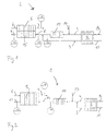
- Fig. 1 is a schematic diagram of an inventive Arrangement of a fuel cell system 1 on the downstream side the fuel cell shown.
- the fuel cell system contains at least one fuel cell 2 with an anode compartment and a cathode compartment and a first media feed line 13 for supplying a first medium to the anode compartment and one second media feed line 14 for supplying a second medium the cathode compartment.
- the upstream side of at least one Fuel cell 2 is not shown in detail.
- Hydrogen is preferably produced from one or more starting materials, e.g. a methanol / water vapor mixture, by reforming won and fed to the fuel cell 2. However, it can other hydrogen-containing starting materials can also be used.
- the An anode effluent is removed from the anode compartment a first media derivative 3, the removal of a Cathode outflow from the cathode compartment takes place via a second Media derivation 4.
- An evaporator 5 is in one with its heat source Flow path of the at least one fuel cell 2 as Heating device arranged so that at least partially Fuel cell exhaust gas downstream of the fuel cell 2 located heat source of the evaporator 5 can be supplied.
- a hydrogen-containing is in the evaporator 5 Educt or mixture evaporated and a gas generation system for Obtaining hydrogen from the vaporized educt or mixture fed. The hydrogen obtained then becomes the Fuel cell 2 supplied as operating resources.
- the evaporator 5 with an outflow of the fuel cell heated directly or indirectly. In this case, educt or mixture and fuel cell exhaust gas in direct current or in Flow counter current through the evaporator 5.
- the evaporator 5 is included a catalytic burner 15 heated.
- the cathode outflow 4 and the anode waste stream 3 are mixed, the evaporator 5 as Reaction medium 8 fed and there in the catalytic burner 15 burned catalytically.
- the reaction medium gives 8 Energy from the educt 6 to be evaporated and evaporates it at least partially.
- the evaporated educt 7 is then e.g. obtained hydrogen in a reformer and the fuel cell 2 fed.
- the at least partially converted reaction medium 8 is the medium 9 from the catalytic burner part 15 of the Evaporator 5 removed.
- a load jump occurs e.g. more electrical power from required the fuel cell 2, more educt, preferably Methanol, the gas generating system of the fuel cell 2 be added. Due to the increased supply of cold, unevaporated educt 6, the temperature in the evaporator 5 drops, if not more energy to vaporize and generate one sufficient amount of the evaporated starting material 7 is provided becomes.
- additional fuel 10 for example Methanol or another suitable medium, are metered in, which in the catalytic burner 15 of the evaporator 5 can also supply energy for evaporation.
- the steam temperature of the evaporated equipment 7 with a temperature sensor T1 supervised.
- the temperature values of the temperature sensor T1 can the steam temperature according to the invention to a predetermined Temperature can be regulated.
- the vapor temperature is constant to keep a predetermined value. In the event of deviations from the given steam temperature, which are registered by T1, can be advantageous by controlling the temperature accordingly Amount of hydrogen in the anode waste stream 3 can be changed by the Evaporator 5 to heat more or less and a predetermined Maintain steam temperature.
- a corresponding amount of fuel 10 additionally in the catalytic burner 15 of the evaporator 5 be added.
- the dosage of the fuel 10 can in the Burner 15 take place in the cathode downstream 4 or in the mixed stream of cathode waste stream 4 and anode waste stream 3 or also in the anode waste stream 3.
- a given base load Evaporator 5 with a substantially constant Cover hydrogen content in the anode exhaust gas 3 and at increased Power requirement on the evaporator 5 only increased add additional fuel 10 to meet the power requirement of the evaporator 5 to cover.
- the metering of the fuel 10 is done so that a predetermined steam temperature at T1 can be met.
- the system can change the load follow faster than with a variation of the hydrogen content in the anode waste stream 3 alone.
- Temperature sensors T3, T2 can also be provided the inlet temperature and / or the outlet temperature of the in the catalytic burner 15 of the evaporator 5 entering or to determine from this emerging medium 8 or 9.
- the temperature difference ⁇ T 2-3 between T2 and T3 can also be used as a control variable for temperature control and accordingly in the event of an impermissible deviation of the temperature difference ⁇ T 2-3 from a predetermined one Value of the hydrogen content in the anode effluent 3 and / or a fuel addition of the fuel 10 can be influenced. If the temperature difference ⁇ T 2-3 is too high, the evaporator 5 is overloaded since it has to evaporate too much educt. More hydrogen and / or fuel 10 must be supplied. If the temperature difference ⁇ T 2-3 is too low, the evaporator 5 is underutilized since only a small amount of starting material is evaporated.
- the output temperature at T2 or the input temperature T3 can also be provided as a control variable for the temperature control.
- an additional can Burner 11 may be provided in the cathode downstream 4 additional fuel 10 before the evaporator 5 burns catalytically and so the reaction medium 8 to a brings higher temperature, so that more thermal energy in Catalytic burner 15 of the evaporator 5 is available.
- Another advantage of such a pre-burner 11 is that Improvement of the emission values with an additional Addition of fuel to the fuel 10.
- the anode outflow 3 is advantageously downstream of the burner 11 mixed with the cathode effluent 4. It can be a Temperature sensor T4 can be provided to determine the output temperature to monitor the pre-burner 11.
- the amount of hydrogen in the anode effluent 3 is regulated so that always enough energy to evaporate the feed 6 im Evaporator 5 is present.
- the amount of hydrogen in the Anode effluent 3 can e.g. so regulate that one more or Less large excess of hydrogen due to the fuel cell 2 is sent. It may be convenient to adjust the amount of hydrogen To keep anode effluent 3 essentially constant. In this Case is the temperature control of the steam temperature or the Temperature of the catalytic burner 15 of the evaporator 5 by adding the additional fuel 10 alone enables. This is advantageous for the dynamics.
- the Using a burner 11 is convenient to avoid unwanted To avoid emissions.
- FIG. 2 is another preferred arrangement of a Fuel cell system 1 on the downstream side of the Fuel cell shown.
- the same elements as in FIG. 1 are identified by the same reference numerals.
- the evaporator 5 is on Hot gas evaporator, in which the hot exhaust gas of the burner 11 as Heat transfer medium 12 is used to an educt 6 evaporate.
- the anode waste stream 3 and the cathode waste stream 4 are mixed and fed to the catalytic burner 11 which is arranged downstream of the fuel cell 2.
- Fuel cell exhaust gas preferably burned catalytically and provides a heat transfer medium 12 with high temperature, which is supplied to the evaporator 5.
- upstream of the Burner 11 supplied additional resources 10 be in addition to the temperature of the heat transfer medium increase.
- a certain amount of educt 6 to be evaporated is proportional to a certain temperature difference ⁇ T 2-3 of the heat transfer medium 12 with a constant gas flow.
- the amount of educt to be evaporated can also be derived from the inlet temperature of the heat transfer medium 12 into the evaporator 5 by means of sensor T3 which thermal energy is required for evaporation and the inlet temperature via the variation of the amount of hydrogen in the anode waste stream 3 and / or be increased or decreased accordingly by varying the fuel addition.
- the temperature difference ⁇ T 2-3 of the heat transfer medium 12 is kept as constant as possible with a variable gas flow. It then emerges that a suitable amount of energy is provided for the evaporation of the starting material in the evaporator 5.
- the amount of hydrogen in the downstream of the fuel cell 2 Anode exhaust 3 determined at least indirectly.
- the jump in load changes the amount of hydrogen in the outflow 3 of the Anode quickly.
- a hydrogen sensor can be used in the anode outflow 4 and / or an oxygen sensor, preferably a lambda probe, in the cathode downstream 3. From a signal from Oxygen sensor can be the hydrogen conversion in the Determine fuel cell 2 and thus the hydrogen content in the Anode exhaust 3.
- Another preferred option is one Concentration measurement in the downstream after the mixing point of Anode exhaust 3 and cathode exhaust 4. Another cheap It is possible to determine the temperature after the Burner 11 at T3, which also the amount of hydrogen in the Anode waste stream 3 reflects.
- the advantage is that that the vapor temperature of the evaporated educt 7 faster can be regulated.
- the advantages of the invention are the fact that the System efficiency of the fuel cell system increased favorably is because the gas mass flows on the heating side of the evaporator 5 can be significantly reduced.
- the additional monitoring of the absolute amount of hydrogen in the anode exhaust has the advantage of further increasing the System dynamics.
- the amount of hydrogen changes at one Load jump, additional fuel 10 can very quickly directly be added to the burner 11 and / or the burner 15.
Landscapes
- Life Sciences & Earth Sciences (AREA)
- Engineering & Computer Science (AREA)
- Manufacturing & Machinery (AREA)
- Sustainable Development (AREA)
- Sustainable Energy (AREA)
- Chemical & Material Sciences (AREA)
- Chemical Kinetics & Catalysis (AREA)
- Electrochemistry (AREA)
- General Chemical & Material Sciences (AREA)
- Fuel Cell (AREA)
Abstract
Description
- Fig. 1
- eine Prinzipdarstellung einer bevorzugten Vorrichtung zur Durchführung des Verfahrens und
- Fig. 2
- eine Prinzipdarstellung einer weiteren bevorzugten Vorrichtung zur Durchführung des Verfahrens.
Claims (13)
- Brennstoffzellensystem (1) mit zumindest einer Brennstoffzelle (2) mit einem Anodenraum und einem Kathodenraum, einer ersten Medienzuleitung (13) zur Zufuhr eines ersten Mediums (6, 7) zu dem Anodenraum und einer ersten Medienableitung zur Abfuhr eines Anodenabstroms (3) aus dem Anodenraum und einer zweiten Medienzuleitung (14) zur Zufuhr eines zweiten Mediums zu dem Kathodenraum und einer zweiten Medienableitung zur Abfuhr eines Kathodenabstroms (4) aus dem Kathodenraum und einer stromab der zumindest einen Brennstoffzelle (2) angeordneten Erwärmungseinrichtung (5), welche mit einem Abstrom (3, 4) der zumindest einen Brennstoffzelle (2) beaufschlagbar ist,
dadurch gekennzeichnet,daß die Erwärmungseinrichtung einen Verdampfer (5) umfaßt,daß der Verdampfer (5) im Strömungsweg eines Edukts zur Bereitstellung eines Betriebsmittels der zumindest einen Brennstoffzelle (2) angeordnet ist unddaß Mittel zur Regelung der Dampftemperatur des im Verdampfer verdampften ersten Mediums (7) auf eine vorgegebene Temperatur oderdaß Mittel zur Regelung der Temperatur eines Wärmeträgermediums (8, 12) des Verdampfers auf eine vorgegebene Temperatur vorgesehen sind. - Brennstoffzellensystem nach Anspruch 1,
dadurch gekennzeichnet, daß der Verdampfer (5) einen katalytischen Brenner (15) als Wärmequelle aufweist. - Brennstoffzellensystem nach Anspruch 1,
dadurch gekennzeichnet, daß stromauf des Verdampfers (5) ein katalytischer Brenner (11) angeordnet ist, dessen Abgas als Wärmeträgermedium (12) dem Verdampfer (5) zugeführt ist, wobei der Brenner (11) im Strömungsweg von Anodenabstrom (3) und Kathodenabstrom (4) angeordnet ist. - Brennstoffzellensystem nach Anspruch 2,
dadurch gekennzeichnet, daß im Kathodenabstrom (4) stromauf des Verdampfers (5) ein katalytischer Brenner (11) vorgesehen ist, der mit dem Brennmittel (10) beaufschlagbar ist. - Brennstoffzellensystem nach Anspruch 1,
dadurch gekennzeichnet, daß im Kathodenabstrom (4) stromauf des katalytischen Brenners (11, 15) eine Zufuhr von Brennmittel (10) vorgesehen ist, welches in Abhängigkeit von der Dampftemperatur oder einer Wärmeträgertemperatur zudosierbar ist. - Brennstoffzellensystem nach Anspruch 1,
dadurch gekennzeichnet, daß eine Wasserstoffmenge im Anodenabstrom (3) abhängig von der Dampftemperatur einstellbar ist. - Brennstoffzellensystem nach Anspruch 1,
dadurch gekennzeichnet, daß stromab der zumindest einen Brennstoffzelle (2) ein Wasserstoffsensor und/oder ein Sauerstoffsensor angeordnet ist. - Verfahren zum Betreiben eines Brennstoffzellensystems (1) mit zumindest einer Brennstoffzelle (2) mit einem Anodenraum und einem Kathodenraum, einer ersten Medienzuleitung (13) zur Zufuhr eines ersten Mediums zu dem Anodenraum und einer ersten Medienableitung zur Abfuhr eines Anodenabstroms (3) vom Anodenraum und einer zweiten Medienzuleitung (14) zur Zufuhr eines zweiten Mediums zu dem Kathodenraum und einer zweiten Medienableitung zur Abfuhr eines Kathodenabstroms (4) vom Kathodenraum und einer stromab der zumindest einen Brennstoffzelle (2) angeordneten Erwärmungseinrichtung (5), welche mit Brennstoffzellenabstrom (4, 3) beaufschlagt wird,
dadurch gekennzeichnet, daß in einem Verdampfer (5) ein Edukt (6, 7) verdampft wird, wobei die Dampftemperatur des im Verdampfer (5) zu verdampfenden Edukts (6, 7) oder die Temperatur eines Wärmeträgermediums (8, 12) des Verdampfers (5) auf eine vorgegebene Temperatur geregelt wird, indem in Abhängigkeit von der Dampftemperatur oder der Wärmeträgertemperatur eine Wasserstoffmenge im Anodenabstrom (3) verändert und/oder zustromseits des Verdampfers (5) ein Brennmittel (10) zudosiert wird. - Verfahren nach Anspruch 8,
dadurch gekennzeichnet, daß der Kathodenabstrom (4) und der Anodenabstrom (3) in einem katalytischen Brenner (15) umgesetzt werden und der Verdampfer (5) von dem Brenner (15) beheizt wird. - Verfahren nach Anspruch 8,
dadurch gekennzeichnet, daß der Kathodenabstrom (4) in einem Brenner (11) umgesetzt wird und der Brennerabstrom (8) und der Anodenabstrom (3) dem Verdampfer (5) zur katalytischen Verbrennung zugeführt werden. - Verfahren nach Anspruch 8,
dadurch gekennzeichnet, daß der Kathodenabstrom (4) und der Anodenabstrom (3) in einem katalytischen Brenner (11) umgesetzt werden und der heiße Abstrom des Brenners (11) dem Verdampfer (5) als Wärmeträgermedium (8, 12) zugeführt wird. - Verfahren nach Anspruch 10 oder 11,
dadurch gekennzeichnet, daß dem Brenner (11) zusätzlich Brennmittel (10) in Abhängigkeit von der Dampftemperatur oder einer Wärmeträgertemperatur des Verdampfers (5) zugeführt wird. - Verfahren nach Anspruch 8,
dadurch gekennzeichnet, daß die Wasserstoffmenge im Anodenabstroms (3) zumindest mittelbar bestimmt wird und das Brennmittel (10) in Abhängigkeit von der Wasserstoffmenge zudosiert wird.
Applications Claiming Priority (2)
| Application Number | Priority Date | Filing Date | Title |
|---|---|---|---|
| DE10015653A DE10015653A1 (de) | 2000-03-29 | 2000-03-29 | Brennstoffzellensystem und Verfahren zum Betreiben eines Brennstoffzellensystems |
| DE10015653 | 2000-03-29 |
Publications (3)
| Publication Number | Publication Date |
|---|---|
| EP1139473A2 true EP1139473A2 (de) | 2001-10-04 |
| EP1139473A3 EP1139473A3 (de) | 2004-02-18 |
| EP1139473B1 EP1139473B1 (de) | 2007-05-16 |
Family
ID=7636865
Family Applications (1)
| Application Number | Title | Priority Date | Filing Date |
|---|---|---|---|
| EP01105628A Expired - Lifetime EP1139473B1 (de) | 2000-03-29 | 2001-03-07 | Brennstoffzellensystem und Verfahren zum Betreiben eines Brennstoffzellensystems |
Country Status (3)
| Country | Link |
|---|---|
| US (1) | US20010046617A1 (de) |
| EP (1) | EP1139473B1 (de) |
| DE (2) | DE10015653A1 (de) |
Cited By (2)
| Publication number | Priority date | Publication date | Assignee | Title |
|---|---|---|---|---|
| WO2017092908A1 (de) * | 2015-11-30 | 2017-06-08 | Robert Bosch Gmbh | Brennstoffzellensystem |
| WO2019115281A1 (de) * | 2017-12-13 | 2019-06-20 | Robert Bosch Gmbh | Brennstoffzellenregelverfahren |
Families Citing this family (1)
| Publication number | Priority date | Publication date | Assignee | Title |
|---|---|---|---|---|
| CN112993315A (zh) * | 2019-12-14 | 2021-06-18 | 中国科学院大连化学物理研究所 | 一种热量耦合甲醇重整制氢燃料电池系统 |
Family Cites Families (2)
| Publication number | Priority date | Publication date | Assignee | Title |
|---|---|---|---|---|
| JPH09315801A (ja) * | 1996-03-26 | 1997-12-09 | Toyota Motor Corp | 燃料改質方法と燃料改質装置ならびに該燃料改質装置を備えた燃料電池システム |
| JP4000608B2 (ja) * | 1996-11-07 | 2007-10-31 | トヨタ自動車株式会社 | 水素製造充填装置および電気自動車 |
-
2000
- 2000-03-29 DE DE10015653A patent/DE10015653A1/de not_active Ceased
-
2001
- 2001-03-07 DE DE50112499T patent/DE50112499D1/de not_active Expired - Lifetime
- 2001-03-07 EP EP01105628A patent/EP1139473B1/de not_active Expired - Lifetime
- 2001-03-29 US US09/820,319 patent/US20010046617A1/en not_active Abandoned
Cited By (2)
| Publication number | Priority date | Publication date | Assignee | Title |
|---|---|---|---|---|
| WO2017092908A1 (de) * | 2015-11-30 | 2017-06-08 | Robert Bosch Gmbh | Brennstoffzellensystem |
| WO2019115281A1 (de) * | 2017-12-13 | 2019-06-20 | Robert Bosch Gmbh | Brennstoffzellenregelverfahren |
Also Published As
| Publication number | Publication date |
|---|---|
| DE50112499D1 (de) | 2007-06-28 |
| DE10015653A1 (de) | 2001-10-11 |
| EP1139473B1 (de) | 2007-05-16 |
| EP1139473A3 (de) | 2004-02-18 |
| US20010046617A1 (en) | 2001-11-29 |
Similar Documents
| Publication | Publication Date | Title |
|---|---|---|
| DE60312677T2 (de) | Brennstoffzellen sauerstoffentfernung und vorbereitungsystem | |
| DE19825772A1 (de) | Verfahren und Vorrichtung zum Umwandeln von Brennstoff und Brennstoffzellensystem mit einer darin vorgesehenen Brennstoffwandlungsvorrichtung | |
| EP0831055A2 (de) | Zentrale Heizvorrichtung für ein Gaserzeugungssystem | |
| DE19754013A1 (de) | Vorrichtung und Verfahren zur Wasserdampfreformierung eines Kohlenwasserstoffs | |
| DE10118148A1 (de) | Verbrennungserwärmungsvorrichtung, Brennstoffreformierapparat mit Verbrennungserwärmungsvorrichtung und Brennstoffzellensytem | |
| DE102004059647B4 (de) | Verfahren zum Regenerieren eines Reformers | |
| DE10244883B4 (de) | Heizsystem für ein Fahrzeug | |
| DE10136970A1 (de) | Vorrichtung zur Erzeugung von wasserstoffhaltigem Gas für eine Brennstoffzellenanlage | |
| EP1139473B1 (de) | Brennstoffzellensystem und Verfahren zum Betreiben eines Brennstoffzellensystems | |
| EP1256141B1 (de) | System zur vorsorgung von wenigstens zwei komponenten eines gaserzeugungssystems | |
| EP1519894A2 (de) | Verfahren zum starten eines gaserzeugungssystems | |
| DE19918997C2 (de) | Verfahren zum Betrieb einer Anlage zur Wasserdampfreformierung von Kohlenwasserstoffen, insbesondere Methanol, sowie entsprechende Anlage | |
| WO2008028439A1 (de) | Brennstoffzellensystem und verfahren zum beeinflussen des wärme- und temperaturhaushaltes eines brennstoffzellenstapels | |
| DE10297091T5 (de) | System und Verfahren zum Zubereiten von Brennstoff für ein Brennstoffaufbereitungssystem | |
| EP1304310A2 (de) | Verfahren und Vorrichtung zur Reformierung flüssiger Kohlenwasserstoffgemische | |
| DE10003275B4 (de) | Vorrichtung zum Verdampfen und/oder Überhitzen eines Brennstoffs | |
| EP1753061B1 (de) | Verfahren zum Starten einer Brennstoffzellenanlage | |
| DE102007018311A1 (de) | Zweistufiger Reformer und Verfahren zum Betreiben eines Reformers | |
| DE10025667B4 (de) | Verfahren zum Betreiben einer Gaserzeugungsvorrichtung in einem Brennstoffzellensystem | |
| DE10296673T5 (de) | Brennstoffzellen-Stromerzeugungsanlage | |
| WO2001041240A2 (de) | Brennstoffzellensystem | |
| DE102008005838B4 (de) | Kraftfahrzeug mit Reformer | |
| DE10222802B4 (de) | Verfahren zum Betreiben eines Gaserzeugungssystems | |
| DE10222804C1 (de) | Gaserzeugungssystem zum Erzeugen von nahezu reinem Wasserstoff und Verfahren zum Starten eines solchen Gaserzeugungssytems | |
| DE10222803A1 (de) | Verfahren zum Betreiben eines Gaserzeugungssystems zum Bereitstellen eines wasserstoffhaltigen Gases |
Legal Events
| Date | Code | Title | Description |
|---|---|---|---|
| PUAI | Public reference made under article 153(3) epc to a published international application that has entered the european phase |
Free format text: ORIGINAL CODE: 0009012 |
|
| AK | Designated contracting states |
Kind code of ref document: A2 Designated state(s): AT BE CH CY DE DK ES FI FR GB GR IE IT LI LU MC NL PT SE TR |
|
| AX | Request for extension of the european patent |
Free format text: AL;LT;LV;MK;RO;SI |
|
| RIN1 | Information on inventor provided before grant (corrected) |
Inventor name: SCHAEFER, MARTIN Inventor name: MOTZET, BRUNO Inventor name: SCHUKRAFT, ANDREAS Inventor name: TISCHLER, ALOIS Inventor name: SUESS, ALEXANDER Inventor name: GOLD, GREGOR |
|
| RAP1 | Party data changed (applicant data changed or rights of an application transferred) |
Owner name: BALLARD POWER SYSTEMS AG |
|
| PUAL | Search report despatched |
Free format text: ORIGINAL CODE: 0009013 |
|
| AK | Designated contracting states |
Kind code of ref document: A3 Designated state(s): AT BE CH CY DE DK ES FI FR GB GR IE IT LI LU MC NL PT SE TR |
|
| AX | Request for extension of the european patent |
Extension state: AL LT LV MK RO SI |
|
| AKX | Designation fees paid |
Designated state(s): DE FR GB IT |
|
| 17P | Request for examination filed |
Effective date: 20041020 |
|
| RAP1 | Party data changed (applicant data changed or rights of an application transferred) |
Owner name: NUCELLSYS GMBH |
|
| GRAP | Despatch of communication of intention to grant a patent |
Free format text: ORIGINAL CODE: EPIDOSNIGR1 |
|
| GRAS | Grant fee paid |
Free format text: ORIGINAL CODE: EPIDOSNIGR3 |
|
| GRAA | (expected) grant |
Free format text: ORIGINAL CODE: 0009210 |
|
| AK | Designated contracting states |
Kind code of ref document: B1 Designated state(s): DE FR GB IT |
|
| REG | Reference to a national code |
Ref country code: GB Ref legal event code: FG4D Free format text: NOT ENGLISH |
|
| REF | Corresponds to: |
Ref document number: 50112499 Country of ref document: DE Date of ref document: 20070628 Kind code of ref document: P |
|
| GBT | Gb: translation of ep patent filed (gb section 77(6)(a)/1977) |
Effective date: 20070702 |
|
| ET | Fr: translation filed | ||
| PLBE | No opposition filed within time limit |
Free format text: ORIGINAL CODE: 0009261 |
|
| STAA | Information on the status of an ep patent application or granted ep patent |
Free format text: STATUS: NO OPPOSITION FILED WITHIN TIME LIMIT |
|
| 26N | No opposition filed |
Effective date: 20080219 |
|
| PGFP | Annual fee paid to national office [announced via postgrant information from national office to epo] |
Ref country code: FR Payment date: 20100402 Year of fee payment: 10 |
|
| PGFP | Annual fee paid to national office [announced via postgrant information from national office to epo] |
Ref country code: GB Payment date: 20100322 Year of fee payment: 10 |
|
| PGFP | Annual fee paid to national office [announced via postgrant information from national office to epo] |
Ref country code: DE Payment date: 20100419 Year of fee payment: 10 Ref country code: IT Payment date: 20100327 Year of fee payment: 10 |
|
| GBPC | Gb: european patent ceased through non-payment of renewal fee |
Effective date: 20110307 |
|
| REG | Reference to a national code |
Ref country code: FR Ref legal event code: ST Effective date: 20111130 |
|
| PG25 | Lapsed in a contracting state [announced via postgrant information from national office to epo] |
Ref country code: DE Free format text: LAPSE BECAUSE OF NON-PAYMENT OF DUE FEES Effective date: 20111001 Ref country code: FR Free format text: LAPSE BECAUSE OF NON-PAYMENT OF DUE FEES Effective date: 20110331 |
|
| REG | Reference to a national code |
Ref country code: DE Ref legal event code: R119 Ref document number: 50112499 Country of ref document: DE Effective date: 20111001 |
|
| PG25 | Lapsed in a contracting state [announced via postgrant information from national office to epo] |
Ref country code: GB Free format text: LAPSE BECAUSE OF NON-PAYMENT OF DUE FEES Effective date: 20110307 Ref country code: IT Free format text: LAPSE BECAUSE OF NON-PAYMENT OF DUE FEES Effective date: 20110307 |