EP1139291A2 - Verfahren zur Visualisierung von Zeitsequenzen von 3D optischen Fluoreszenzmikroskopie-Bilder - Google Patents
Verfahren zur Visualisierung von Zeitsequenzen von 3D optischen Fluoreszenzmikroskopie-Bilder Download PDFInfo
- Publication number
- EP1139291A2 EP1139291A2 EP01303028A EP01303028A EP1139291A2 EP 1139291 A2 EP1139291 A2 EP 1139291A2 EP 01303028 A EP01303028 A EP 01303028A EP 01303028 A EP01303028 A EP 01303028A EP 1139291 A2 EP1139291 A2 EP 1139291A2
- Authority
- EP
- European Patent Office
- Prior art keywords
- image
- data
- images
- volume
- run
- Prior art date
- Legal status (The legal status is an assumption and is not a legal conclusion. Google has not performed a legal analysis and makes no representation as to the accuracy of the status listed.)
- Withdrawn
Links
Images






Classifications
-
- G—PHYSICS
- G06—COMPUTING OR CALCULATING; COUNTING
- G06T—IMAGE DATA PROCESSING OR GENERATION, IN GENERAL
- G06T9/00—Image coding
-
- G—PHYSICS
- G06—COMPUTING OR CALCULATING; COUNTING
- G06T—IMAGE DATA PROCESSING OR GENERATION, IN GENERAL
- G06T13/00—Animation
-
- H—ELECTRICITY
- H04—ELECTRIC COMMUNICATION TECHNIQUE
- H04N—PICTORIAL COMMUNICATION, e.g. TELEVISION
- H04N19/00—Methods or arrangements for coding, decoding, compressing or decompressing digital video signals
- H04N19/50—Methods or arrangements for coding, decoding, compressing or decompressing digital video signals using predictive coding
- H04N19/503—Methods or arrangements for coding, decoding, compressing or decompressing digital video signals using predictive coding involving temporal prediction
-
- H—ELECTRICITY
- H04—ELECTRIC COMMUNICATION TECHNIQUE
- H04N—PICTORIAL COMMUNICATION, e.g. TELEVISION
- H04N19/00—Methods or arrangements for coding, decoding, compressing or decompressing digital video signals
- H04N19/50—Methods or arrangements for coding, decoding, compressing or decompressing digital video signals using predictive coding
- H04N19/597—Methods or arrangements for coding, decoding, compressing or decompressing digital video signals using predictive coding specially adapted for multi-view video sequence encoding
-
- H—ELECTRICITY
- H04—ELECTRIC COMMUNICATION TECHNIQUE
- H04N—PICTORIAL COMMUNICATION, e.g. TELEVISION
- H04N19/00—Methods or arrangements for coding, decoding, compressing or decompressing digital video signals
- H04N19/90—Methods or arrangements for coding, decoding, compressing or decompressing digital video signals using coding techniques not provided for in groups H04N19/10-H04N19/85, e.g. fractals
- H04N19/91—Entropy coding, e.g. variable length coding [VLC] or arithmetic coding
Definitions
- This invention relates to a method for the visualisation of 4D data, and more particularly to the rendering of sequences of 3D data sets comprised of optical fluorescence microscopy images.
- the first methodology involves obtaining a 2D image from each 3D image stack by extracting data from a planar "slice" through the 3D data.
- image stack refers a two-dimensional, planar array of voxels. When a plurality of such image stacks are situated one atop another, a three-dimensional volume is defined. Two-dimensional images obtained in this way from each 3D image stack can then be combined to form a time sequence.
- a second methodology involves the creation of a 2D image obtained from each 3D image stack by projecting data onto a plane perpendicular to a "view direction".
- the projection can vary in complexity, from taking the brightest point along a "ray" from a point on the view plane, to including effects of opacity to obscure occluded objects.
- both methodologies derive a 2D image from each 3D data stack in isolation from the other 3D images in the 4D data. As such, they fail to exploit the substantial coherence in time between subsequent 3D images. Numerous examples of these methodologies are detailed in the following.
- JPEG Joint Photographic Experts Group
- MPEG Moving Pictures Experts Group
- a second embodiment of the present invention is drawn to the aforementioned method wherein the 4D image data is a plurality of 3D images that vary with respect to time.
- Yet another embodiment of the present invention is drawn to the aforementioned method wherein the processing step further comprises compressing a first 3D image using run length encoding (RLE), detecting changes between the first 3D image and subsequent successive time varied 3D images, compressing the data of each, subsequent successive time varying 3D image using run-length encoding, and storing the first compressed 3D image and compressed data of each of the subsequent successive time varying 3D image in an electronic format.
- RLE run length encoding
- Yet another embodiment of the present invention is drawn to the aforementioned method wherein the plurality of 2D images is displayed in graphic form.
- Yet another embodiment of the present invention is drawn to the aforementioned method wherein the plurality of 2D images is stored in an electronic format.
- Yet another embodiment of the present invention is drawn to the aforementioned method wherein the processing step is performed off-line.
- Yet another embodiment of the present invention is drawn to the aforementioned method wherein the converting step occurs interactively.
- Still another embodiment of the present invention is drawn to the aforementioned method further comprising the steps of selecting an opacity threshold value, and classifying sub-volumes comprising the plurality of time varying 3D images according to the opacity threshold value.
- Still another embodiment of the present invention is drawn to the aforementioned method wherein change detection is accomplished through the application of a chi-squared test applied to successive time varying 3D images.
- Still another embodiment of the present invention is drawn to the aforementioned method wherein the chi-squared threshold value is set to .95.
- Still another embodiment of the present invention is drawn to the aforementioned method wherein the opacity threshold value is derived from an opacity function.
- Yet another embodiment of the present invention is drawn to the aforementioned method wherein the application of a chi-squared test further comprises the steps of dividing each successive time varying 3D image into a plurality of sub-volume voxels, and performing the chi-squared test on corresponding voxels contained in each successive time varying 3D image.
- Yet another embodiment of the present invention is drawn to the aforementioned method wherein the run length encoding of the first 3D image further comprises the step of storing only runs of non-transparent voxels.
- Yet another embodiment of the present invention is drawn to the aforementioned method wherein the compressing of data using run-length encoding is only performed on the voxels in which change was detected.
- Yet another embodiment of the present invention is drawn to the aforementioned method wherein the run length encoded data is stored in two complimentary ways; the first of the two ways containing the run lengths and the second of the two ways containing non-transparent voxel data.
- Yet another embodiment of the present invention is drawn to the aforementioned method wherein the compressed first 3D image and the compressed data of each subsequent successive time varying 3D image are stored in three different orientations.
- Yet another embodiment of the present invention is drawn to the aforementioned method wherein the three different orientations correspond to orthogonal axes in three dimensional space.
- converting the pre-processed 4D image data further comprises the steps of providing access to the first compressed 3D image to a processor, converting the first compressed 3D image into a modified RLE format, rendering the first compressed 3D image as a plurality of 2D intermediate images, compositing the 2D intermediate images to form a final 2D intermediate image, and warping the final 2D intermediate image to form the 2D display image.
- Yet another embodiment of the present invention is drawn to the aforementioned method wherein the rendering of the 2D intermediate image employs a Shear-Warp algorithm.
- Yet another embodiment of the present invention is drawn to the aforementioned method wherein the additional step of rendering subsequent 2D display images comprises the steps of loading the run length encoded changes for each successive time varying 3D image, incorporating the encoded changes into the modified RLE format, and rendering the changed regions.
- Yet another embodiment of the present invention is drawn to a method for compressing 4D image data to accelerate the visualization of the data comprising the sequential steps of compressing a first 3D image using run length encoding (RLE), detecting changes between the first 3D image and subsequent time varied 3D images by dividing each subsequent time varying 3D image into a plurality of sub-volume voxels and performing a chi-squared test on corresponding voxels contained in each subsequent time varying 3D image and the sub-volume voxels in which was last detected a change, and compressing the data of each, subsequent successive time varying 3D image using run-length encoding.
- RLE run length encoding
- the present invention solves the deficiencies of existing methods through the provision of a method for enabling the visualization of 4D data.
- the present invention employs the use of a data compression technique capable of accelerating the process of performing the computationally intensive task of accessing large 4D data sets and producing graphical representations therefrom.
- volume element values either do not change or change very slowly over time. This property is exploited by the present invention to decrease the computational requirements of time rendering whereby subsequent temporal visualizations of 4D data are created.
- the present invention approaches the visualization of 4D data in two stages.
- An initial stage of pre-processing is performed to transform the 4D data into a representation from which the time sequence of rendered 2D images may be more easily generated.
- the pre-processing identifies in the second 3D data volume the changes between it and the first data volume. This pre-processing is applied to subsequent 3D data volumes, each time identifying the changes between subsequent volumes and the previous volumes.
- the view direction is the vector direction in three-dimensional space from which a user views the 3D data.
- the advantages of the present invention's method of pre-processing are two-fold in nature. First, following pre-processing, only the data of the first 3D data volume in the sequence need be stored in its entirety. Subsequent 3D volumes may be represented by this first volume and the sequence of 3D changes necessary to re-create a current 3D volume. This provides data compression, reducing data storage requirements. As illustrated in the example which follows, the storage space required for a subsequent 3D volume corresponding to an original 3D volume comprising approximately 48 Mbytes is approximately two percent of the original 3D volume.
- visualization of 2D slices through the data may miss certain features or changes in parts of the 3D image that do not lie on the slice.
- Traditional projective techniques applied to a sequence of 3D images are slow due to the computationally intensive nature of the calculations to be performed.
- the process of projective visualization of each 3D data volume in the sequence is computationally simplified as modifications to the 2D image to be rendered take place only where they correspond to changed regions of the 3D data. This results in a reduction in the time to render each 3D data volume into a 2D image.
- the rendering system of the present invention comprises two separate stages, each of which shall be more fully described below.
- the first stage pre-processes the time varying data, detecting changes, compressing the data by using a run-length encoding (RLE) scheme, and storing the data to disk.
- the second stage renders the 4D data to a sequence of 2D images to be displayed or stored.
- the first stage need not be performed in an interactive fashion, but may instead be performed off-line.
- off-line refers to a manner of processing wherein the execution of the processing does not involve active user input.
- the second stage task of rendering the data is ideally performed in an interactive manner.
- rendering in an interactive manner refers to the process of receiving inputs from a user and rendering visualisations corresponding to the user's input data in so short a time as to appear almost contemporaneous with the user's inputs. Such time intervals are generally sub-second in duration though they may include intervals of a magnitude of several seconds.
- the method of the present invention separates the 4D rendering task into two stages comprising a relatively slow encoding of the data which subsequently enables an efficient rendering phase of the data to the displayed.
- No additional hardware is required to perform either stage and a useful side effect of the method is the compression of the data stored to disk or other memory device.
- the performance of the rendering stage is improved by exploiting the spatial and temporal coherence in the 4D data.
- an opacity function is selected and the volumes are classified according to opacity criteria during the pre-processing stage. This opacity aspect of the method's processing further assists to eliminate a portion of the noise in the data through selection of a sufficiently high opacity threshold value.
- one primary crux of the present invention's methodology is the manner by which changes are detected in subsequent 3D volumes so as to compress the volume data.
- the pre-processing stage performs a number of operations the aims of which are to exploit spatial and temporal coherence including the steps of change detection, opacity function selection and classification, and run-length encoding.
- Fig. 1 The process of change detection is described with reference to Fig. 1.
- One method of change detection is simple differencing between voxels in a 3D data volume at time t and the volume at time t+1, followed by a threshold test.
- the threshold test serves to filter out changes that are spurious, arising from noise in the data which does not represent a true change in the structure of the 3D data volume.
- Sub-volumes containing changes are then identified as the 3D "bounding box" of any contiguous, or near contiguous (the separation between changed sub-volumes is less than half the radius of the smaller when its volume is considered as a sphere), change.
- 3D "bounding box" the separation between changed sub-volumes is less than half the radius of the smaller when its volume is considered as a sphere
- Fig. 1a shows an image at time t
- Fig. 1b illustrates the following image at time t+1
- the changed region 11 between the two is identified in Fig. 1c.
- changed region 11 is rectangular in form.
- changed region 11 represents the two-dimensional area in which changes to the structure of the volume exist.
- change detection techniques can be exploited during pre-processing of the volume data, before storing in an electronic form or format, to eliminate the temporal coherence and transform the data into a form that allows encoding of change and fast rendering.
- electronic form refers to any and all modes of storing digital data including, but not limited to, storage on disk drives, optical memory systems, and the like.
- the present invention employs a sophisticated change detection method that recognises that real data will be subject to corruption by noise, and that there therefore exists a need to distinguish between changes due to the noise and real changes in structure between 3D images.
- the approach of the present invention involves dividing each data volume up into sub-volumes or blocks.
- the standard ⁇ 2 criterion is used to determine if the squared difference between two blocks at the same position, but at time t and time t+1, is significant given the noise variance present in the image calculated according to equation 1: where x, y, and z represent orthogonal axes, t represents successive data volumes in time, and ⁇ represents the confidence threshold.
- a ⁇ 2 value is computed for each block in the 3D image at time t+1.
- a threshold value for ⁇ 2 is chosen so that one can be confident to 95% that the changes in the block over time are due to changing structure rather than due to noise. This threshold value is referred to as the chi-squared threshold value. While the 95% confidence level is commonly adopted in the art for such statistical examinations, any suitable confidence level may be employed that is appropriate to the circumstances of the analysis. Blocks that have been identified as changed are stored to disk together with information about the block location in the 3D data volume.
- the noise is assumed to be Gaussian and not to vary as a result of image position.
- the noise variance in the 4D image is computed by subtracting successive blocks at the same position and computing a variance from this block difference according to equation 1. This process of subtraction serves to suppress structure while identifying variance.
- a histogram of the number of blocks of a particular variance will peak at twice the background noise variance. The factor of two in the variance is due to the differencing of the two volumes. Finding the peak in this way is valid if the 4D image sequence is dominated by blocks that do not contain structural changes. If the images are represented by integers, 1/12 is added to the estimated noise variance to compensate for quantization errors.
- CCD charge-couple device
- the voxel density as perceived (sampled) by the CCD cell is Poisson distributed with a mean and variance equal to the real voxel density which is unknown.
- the voxel variance is approximated with the sampled voxel density and the variance in the denominator of the chi-squared fraction is replaced with the average of two successive (in time) voxels. Also, since the variance is different for every voxel, the sum over every voxel is expanded. To test the hypothesis, the same thresholds as in the Gaussian noise case are used.
- a methodology is employed to address changes which occur in a volume over time but which occur so slowly as to escape detection. Specifically, because the previously described method for detecting changes proceeds by comparing successive blocks at the same position, slight but real changes that occur at a given block or volume over time may appear to be slight in successive blocks and thus escape detection. However, if such slight changes are indicative of small but time persistent changes in the underlying volume, the sum of these small changes over time can be sizeable while escaping detection.
- the opacity function task requires the input of a function for determining whether or not a voxel is to be considered opaque.
- An opacity function is chosen that determines what levels in the image data are to be treated as transparent or opaque. Once a voxel is determined to be opaque, it is treated as blankspace. As used herein, blankspace refers to a voxel which does not contain a value and therefore does not need to be rendered in order to derive the final image.
- the opacity function is user defined and is conventional in its implementation. Classification of the data volume is a conventional method whereby raw volume data is mapped, based on value, to a range of pseudo-colors for purposes of display.
- the last pre-processing step involves the run-length encoding of the data.
- Typical volume data consist of 70-95% blankspace. Exploiting the presence of blankspace can accelerate volume rendering dramatically.
- Volume scanlines comprise one-dimensional arrays of contiguous voxels.
- the RLE scheme of the present invention is illustrated in Fig. 2.
- the RLE scheme is used to store the data as part of the pre-processing phase.
- the RLE scheme encodes the entire first volume using RLE, storing only runs of non-transparent voxels, and then encodes only the changed sub-volumes for the second and subsequent volumes, again using RLE.
- the complete 4D data set can be recovered from the stored RLE.
- the RLE structure used for storage is illustrated in Fig. 2a.
- the storage RLE uses two data structures, one to store the run lengths and the other to store the actual non-transparent voxel data. These data structures are 1-D arrays.
- the run length array stores the lengths of alternate transparent and non-transparent runs of voxels.
- the data values of the non-transparent voxels are stored in sequence in the second array.
- Storage of the subsequent 3D data volumes requires only the storage of small sub-volumes corresponding to the blocks identified as containing changes. These sub-volumes may also contain amounts of blankspace encoded by the RLE.
- the present invention stores three copies of the 4D data.
- Data is normally stored in x, y, z, t order.
- the rendering algorithm described below is most efficient when the z direction is the axis "closest" to the viewing direction. Therefore, during the pre-processing phase, the data is transposed about the x, y, and z axes and stored as three distinct copies of the data each of which is ordered to best suit a particular group of viewing directions. As such, each copy represents one of three different orientations.
- the overhead involved as a result of this transposition and multiple storage of the data is addressed below wherein there is additionally described an extension to the method that reduces this storage overhead.
- the present invention Rather than recreate the original 4D data from the stored RLE, the present invention generates a modified RLE used by the rendering phase of the algorithm.
- the modified RLE is shown in Fig. 2b.
- the modified run length array expands out the alternate runs of transparent and non-transparent voxels to the original size by inserting runs of zeros for the transparent runs between the runs of non-transparent voxels.
- this is augmented by a second piece of information at each location. At the start of a run this information contains the length of the run, whilst elsewhere in a run it stores the distance back to the start of the run.
- the 4D data Once the 4D data has been pre-processed and stored in a RLE form, it must then be rendered to form a sequence of 2D display images.
- the first step in the process of rendering requires the loading of the initial 3D data volume from disk or other electronic storage media. Subsequent loads of images occur at a faster rate as only the RLE of the changed portions needs to be fetched.
- the present invention retrieves only the version of the data that has its primary axis closest to the viewing direction.
- Each 3D image is stored as a linear array of integers representing the run lengths of transparent and non-transparent voxels, together with a array of linked non-transparent voxel data.
- Each scanline of an image starts with a transparent entry 21 and ends with a non-transparent entry 23 for purposes of synchronization (even if the runs are of zero length). Runs of transparent and non-transparent voxels alternate.
- the value stored at each entry in the run-length array is the length of the run of transparent or non-transparent voxels.
- the modified RLE storage of the 3D volume consists of two elements at each x, y, z, position.
- One element is the data value associated with that voxel, the other is either the length of the run or an offset to the start of that run.
- the length of the run is stored in the first position of a run of transparent or non-transparent voxels as shown in Fig. 2b.
- This data structure enables rapid skipping of transparent voxels during rendering, keeps memory accesses in cache order, and allows rapid insertion of changes to the 3D data volume.
- the process of expanding from RLE to modified RLE form consumes the non-transparent data array elements according to the specified lengths of runs in the run length array to form a 3D data volume.
- the next step in rendering the data image requires rendering the 3D data as 2D intermediate "thick slice” images using the Shear-Warp algorithm.
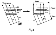
- the Shear-Warp algorithm is an efficient technique for rendering 3D data volumes and is briefly outlined as follows.
- the Shear-Warp factorization method of volume visualization eliminates the arbitrary mapping between object and image space present in ray-tracing algorithms by making all rays 31 pass through volume slices 33 parallel to a co-ordinate axis (vertical) as illustrated in Fig. 3. This is achieved by converting the viewing transformation into a 3D shear, projecting from 3D to 2D, and performing a 2D warp to correct for geometric distortion.
- each slice of the volume is translated by a shearing coefficient, re-sampled and composed from 3D to 2D to form an intermediate image. Once this is done for all the slices in the volume, a 2D warp of the intermediate image must take place in order to generate the final image.
- the present invention extends the utility of the Shear-Warp rendering technique for 4D data visualization through the addition of a plurality of modifications.
- the first of these modifications to the Shear-Warp concerns the compositing stage. This stage of the Shear-Warp accumulates intensity and opacity through the volume. Opacity may be derived from the opacity transfer function derived at an earlier stage and described above.
- Partial ray compositing refers to the ability to divide a ray into two or more parts at any point on the ray and to treat the resulting rays as completely different rays. After each of these sub-rays is composited, one need only to combine them by using the over operator to arrive at a final pixel color or intensity.
- the present invention exploits this partial ray compositing by dividing the data volume into a number of thick slices. These thick slices are each a division of the volume, in the primary axis direction, divided into a number of contiguous slices.
- the ray is split into a number of rays each of which composites voxels belonging to a thick slice.
- Each thick slice typically consists of 4 to 24 slices of the 3D data, and, for convenience, corresponds in width to the distance in the primary direction of the width of the blocks used for change detection.
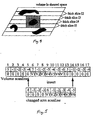
- Each thick slice has associated with it a partial intermediate image that has been composited from the data in the thick slice as illustrated in Fig. 4.
- the 2D image must be warped to produce the image for display. Such warping is performed consistent with the conventional method of the Shear-Warp decomposition of the viewing transformation.
- the stored RLE for the changed blocks may represent one or more sub-volumes where changes took place.
- Each block in RLE form has associated with it information that describes where it is to be inserted into the modified RLE complete volume.
- the rational behind the modified RLE is that the RLE data structure performs well in the case of rendering a single 3D volume, but its use becomes increasingly difficult with a sequence of 3D volumes.
- the RLE structure is a 1-D array into which must be inserted the changes.
- a conventional RLE representation of the data would require moving large amounts of data around to accommodate the inserted data and would comprise resource intensive operation.
- the modified RLE data structure is easy to update and maintains memory coherence.
- the algorithm for inserting runs of voxels into the modified RLE is detailed in Fig. 6 and described more fully below.
- the advantage of this data structure is its efficiency when it comes to updating. Imagine the following situation where a change area scanline needs to be inserted into some position in the volume scanline as illustrated in Fig. 5. All that is desired when inserting a new portion of the scanline is to check (and probably amend) the following and the previous runs and then copy the new portion to the scanline.
- the algorithm for updating a scanline is illustrated in Fig. 6 where R is the scanline length, VB a pointer indicating the position in the volume scanline to insert the new chunk, and offset is the number of voxels to leap.
- the first if-statement 61 in the scanline update algorithm asserts that the offset of the voxel following the last voxel of the portion of the scanline (voxel number 15 in Fig. 5) to be updated is not less than zero. If it greater that zero, no updating of the following run-length is necessary, because the voxel under consideration is at the head of a run. If, on the other hand, the offset is indeed less that zero, it means that the new portion of the scanline overlaps the following run-length and updating is necessary. This is easily done by following the offset to find the head of the run deducting thus the number of voxels in the run and making the voxel under consideration (number 15 in this example) the head voxel. In addition, updating the rest of the run's voxels is needed in order to point to the new head of the run.
- the second if-statement asserts that the offset of the first voxel to be updated (voxel number 5 in Fig. 5) is not less than zero. If it is greater than zero, no action should be made because the head of the new portion coincides with the head of the run. If it is less that zero, all that is required is to follow the offset to the head of the run and reduce the number of voxels belonging to this run by -offset.
- the algorithm may be extended to merge adjacent runs of the same type. Finally, copying of the new voxels to the corresponding positions concludes the task of scanline updating.
- the next step requires the rendering of changed (x, y) regions of thick slices of 3D volume using Shear-Warp.
- the use of thick slices is introduced herein to avoid the situation illustrated in Fig. 7b wherein is illustrated the amount of data to be re-rendered had the thick slice approach not been employed.
- the portion of the 3D volume that changes will affect a number of thick slices. If the intermediate image intensity was formulated by compositing the intermediate images generated by each thick slice, according to equation 4, only a limited number of thick slices will be affected by the change. In the example shown earlier with reference to Fig. 5, only thick slices I 3 , I 4 , and I 5 are affected by the changing object. Consequently, one need recalculate only those three partial intermediate images.
- the changed thick slice intermediate images and the unchanged thick slice intermediate images may be combined using the over operator, described earlier, with respect to equation 4, to derive the final intermediate image intensity.
- the final intermediate image is warped as before to produce the 2D image for display. It is not necessary to re-warp the entire final image, only that portion that has changed with the addition of a border of a few pixels extending beyond.
- the warp operation is computationally expensive, so avoiding a re-warp of the entire image provides further computational savings.
- a test was performed upon a synthetic volume of 257 3 voxels, 8 bits per voxel, that contained 2 hollow spheres, one with radius 65 and thickness 10 voxels and another with radius and thickness of 25 and 5 voxels respectively.
- the application was tested on a Sun Microsystems Ultra10/300Mhz (Sun Microsystems of Palo Alto, California) with 320 MB of RAM. The viewpoint was set to 45 degrees from the z axis.
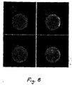
- Fig. 8 depicts four separate rendered images from a sequence of 3D images.
- Fig. 9 illustrates the execution times corresponding to brute force rendering, run length encoding of the data, and rendering utilizing the present invention's methods for exploiting temporal and spatial coherence.
- every voxel in the volume is rendered by using the brute-force version of the Shear-Warp factorization, without considering the spatial and temporal coherence. It is clear that this method is unacceptably slow for interactive applications. Furthermore, the space required to save the whole volume to disk is about 48MB (257 3 , at 3 bytes per voxel), which makes the storage of many volumes prohibitive.
- the RLE to compress the volumes, and store the volumes to disk. Using the RLE eliminates spatial coherence but not temporal coherence. The result is that the rendering becomes faster, but still not fast enough for real-time rendering.
- we detect the changes in the volume by using simple differencing and compress only the changed area using the RLE. This eliminates both spatial and temporal coherence and as a result the rendering part is accelerated significantly.
- Fig. 10 presents the times required in the pre-processing stage of the rendering system, that is, the stage that detects change, run-length encodes and stores the volumes.
- the run-length encoding takes a significant amount of time only when rendering the first volume. That is because the first volume is saved as a whole.
- the change between successive volumes is detected, encoded, and, saved which takes comparatively much less time.
- the change detection method used in the present application is differencing which works well in this case where noise does not corrupt the data. Change detection by simple differencing takes about 1.2 seconds per volume.
- FIG. 11 presents the times required in the pre-processing stage of the rendering system, when the original RLE compression is used on all volumes, without change detection. It becomes apparent that the execution time in this case is significantly larger.
- Fig. 12 compares the size occupied by the original volume to the size occupied by the compressed volume after change detection. With change detection and compression, the volume data occupy significantly less disk space.
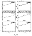
- Fig. 13 demonstrates the effect that the number of thick slices has on the rendering speed.
- the upper line shows the rendering time and the lower the re-compositing time.
- the central idea of this invention is the use of a data compression technique that facilitates the rapid visualisation of 4D data.
- the 4D data In optical fluorescence microscopy the 4D data would be a sequence of 3D data volumes.
- the present invention exploits the spatial coherence and the temporal coherence of the data in such a way that the storage requirements and computational cost of visualisation are reduced.
- the invention implicitly covers any technique that uses a representation of 4D data (or five-dimensional (5D) data as detailed below), derived from optical fluorescence microscopy including transform domain methods such as Discrete Cosine, Fourier, Fourier-Mellin, Wavelet, or other data structures such as, but not limited to, quadtrees, octrees, and hexadecimal-trees that reduce data storage and accelerate subsequent rendering, by any projective visualisation technique, to a sequence of 2D images.
- transform domain methods such as Discrete Cosine, Fourier, Fourier-Mellin, Wavelet, or other data structures such as, but not limited to, quadtrees, octrees, and hexadecimal-trees that reduce data storage and accelerate subsequent rendering, by any projective visualisation technique, to a sequence of 2D images.
- Multi-channel data where several "colors" may be observed under an optical fluorescence microscope can be treated in a similar way.
- the invention implicitly covers such a technique as the data may be stored as RGB (red, green, blue), or similar color representation, or as a number of channels of data collected at different wavelengths. Data may also then be referred to as 5D.
- the representation of the fifth dimension may be explicit as in RGB, or may be subsumed into the classification stage described earlier.
- One useful extension to the technique would be to modify the storage of data.
- Storing one copy of the first volume will require a transposition of the data to bring the primary axis near to the viewing direction in about 60% of cases, this will add a slight delay to the display of the initial image.
- Storing one copy of the changed sub-volumes will require a delay as the image sequence is being generated for each image - this delay will be smaller than that for the first image as the quantities of data are likely to be less. Storing one copy of the first and changed sub-volumes will introduce an overhead at the start of playback and for each generated image. If these delays are acceptable the data storage can be reduced by a factor of three.
Landscapes
- Engineering & Computer Science (AREA)
- Multimedia (AREA)
- Physics & Mathematics (AREA)
- General Physics & Mathematics (AREA)
- Theoretical Computer Science (AREA)
- Signal Processing (AREA)
- Image Generation (AREA)
- Ultra Sonic Daignosis Equipment (AREA)
Applications Claiming Priority (5)
| Application Number | Priority Date | Filing Date | Title |
|---|---|---|---|
| US54026200A | 2000-03-31 | 2000-03-31 | |
| US540262 | 2000-03-31 | ||
| 2001-02-02 | |||
| US09/817,398 US20020012472A1 (en) | 2000-03-31 | 2001-03-26 | Method for visualization of time sequences of 3D optical fluorescence microscopy images |
| US817398 | 2004-04-01 |
Publications (2)
| Publication Number | Publication Date |
|---|---|
| EP1139291A2 true EP1139291A2 (de) | 2001-10-04 |
| EP1139291A3 EP1139291A3 (de) | 2003-10-01 |
Family
ID=27066378
Family Applications (1)
| Application Number | Title | Priority Date | Filing Date |
|---|---|---|---|
| EP01303028A Withdrawn EP1139291A3 (de) | 2000-03-31 | 2001-03-30 | Verfahren zur Visualisierung von Zeitsequenzen von 3D optischen Fluoreszenzmikroskopie-Bilder |
Country Status (2)
| Country | Link |
|---|---|
| US (1) | US20020012472A1 (de) |
| EP (1) | EP1139291A3 (de) |
Cited By (2)
| Publication number | Priority date | Publication date | Assignee | Title |
|---|---|---|---|---|
| WO2004113922A3 (en) * | 2003-06-19 | 2005-06-02 | Applied Precision Llc | System and method employing photokinetic techniques in cell biology imaging applications |
| CN113470127A (zh) * | 2021-09-06 | 2021-10-01 | 成都国星宇航科技有限公司 | 基于星载云检测的光学图像有效压缩方法 |
Families Citing this family (8)
| Publication number | Priority date | Publication date | Assignee | Title |
|---|---|---|---|---|
| US8958654B1 (en) * | 2001-04-25 | 2015-02-17 | Lockheed Martin Corporation | Method and apparatus for enhancing three-dimensional imagery data |
| US8446410B2 (en) * | 2006-05-11 | 2013-05-21 | Anatomage Inc. | Apparatus for generating volumetric image and matching color textured external surface |
| WO2008040116A1 (en) * | 2006-10-02 | 2008-04-10 | Cancercare Manitoba | Methods of detecting and monitoring cancer using 3d analysis of centromeres |
| WO2008045997A2 (en) * | 2006-10-11 | 2008-04-17 | Leica Geosystems Ag | Feature extraction from stereo imagery |
| US20080089577A1 (en) * | 2006-10-11 | 2008-04-17 | Younian Wang | Feature extraction from stereo imagery |
| CA2856419C (en) | 2013-09-20 | 2018-06-26 | Telo Genomics Holdings Corp. | Methods for evaluating alzheimer's disease and disease severity |
| CA3014324A1 (en) | 2016-02-12 | 2017-08-17 | The General Hospital Corporation | Apparatus and methods for high-speed and long depth range imaging using optical coherence tomography |
| KR102880703B1 (ko) * | 2022-09-15 | 2025-11-04 | 한국전자기술연구원 | V-pcc 부호화를 위한 고효율 패치 세그먼트 정제 방법 및 장치 |
Family Cites Families (10)
| Publication number | Priority date | Publication date | Assignee | Title |
|---|---|---|---|---|
| US4679094A (en) * | 1986-10-14 | 1987-07-07 | The Associated Press | Method for compression and transmission of video information |
| US4827413A (en) * | 1987-06-16 | 1989-05-02 | Kabushiki Kaisha Toshiba | Modified back-to-front three dimensional reconstruction algorithm |
| US5805733A (en) * | 1994-12-12 | 1998-09-08 | Apple Computer, Inc. | Method and system for detecting scenes and summarizing video sequences |
| GB9501832D0 (en) * | 1995-01-31 | 1995-03-22 | Videologic Ltd | Texturing and shading of 3-d images |
| US6055330A (en) * | 1996-10-09 | 2000-04-25 | The Trustees Of Columbia University In The City Of New York | Methods and apparatus for performing digital image and video segmentation and compression using 3-D depth information |
| US6262737B1 (en) * | 1998-01-30 | 2001-07-17 | University Of Southern California | 3D mesh compression and coding |
| EP1086412A4 (de) * | 1998-06-08 | 2008-05-07 | Microsoft Corp | Komprimierung von zeitabhängige geometrie |
| US6674430B1 (en) * | 1998-07-16 | 2004-01-06 | The Research Foundation Of State University Of New York | Apparatus and method for real-time volume processing and universal 3D rendering |
| US6501471B1 (en) * | 1999-12-13 | 2002-12-31 | Intel Corporation | Volume rendering |
| US6664955B1 (en) * | 2000-03-15 | 2003-12-16 | Sun Microsystems, Inc. | Graphics system configured to interpolate pixel values |
-
2001
- 2001-03-26 US US09/817,398 patent/US20020012472A1/en not_active Abandoned
- 2001-03-30 EP EP01303028A patent/EP1139291A3/de not_active Withdrawn
Cited By (6)
| Publication number | Priority date | Publication date | Assignee | Title |
|---|---|---|---|---|
| WO2004113922A3 (en) * | 2003-06-19 | 2005-06-02 | Applied Precision Llc | System and method employing photokinetic techniques in cell biology imaging applications |
| US7408176B2 (en) | 2003-06-19 | 2008-08-05 | Applied Precision, Llc | System and method employing photokinetic techniques in cell biology imaging applications |
| US7608840B2 (en) | 2003-06-19 | 2009-10-27 | Applied Precision, Llc | System and method employing photokinetic techniques in cell biology imaging applications |
| US7683345B2 (en) | 2003-06-19 | 2010-03-23 | Applied Precision, Inc. | System and method employing photokinetic techniques in cell biology imaging applications |
| CN113470127A (zh) * | 2021-09-06 | 2021-10-01 | 成都国星宇航科技有限公司 | 基于星载云检测的光学图像有效压缩方法 |
| CN113470127B (zh) * | 2021-09-06 | 2021-11-26 | 成都国星宇航科技有限公司 | 基于星载云检测的光学图像有效压缩方法 |
Also Published As
| Publication number | Publication date |
|---|---|
| EP1139291A3 (de) | 2003-10-01 |
| US20020012472A1 (en) | 2002-01-31 |
Similar Documents
| Publication | Publication Date | Title |
|---|---|---|
| US7324115B2 (en) | Display list compression for a tiled 3-D rendering system | |
| US20220392154A1 (en) | Untransformed display lists in a tile based rendering system | |
| Westermann et al. | Efficiently using graphics hardware in volume rendering applications | |
| US6825847B1 (en) | System and method for real-time compression of pixel colors | |
| Weiler et al. | Hidden surface removal using polygon area sorting | |
| EP1661404B1 (de) | Differenz-codierung durch verwendung eines 3d-graphikprozessors | |
| US9619937B2 (en) | Methods and apparatus for processing computer graphics primitives in tile-based graphics rendering system | |
| DE69636599T2 (de) | Verfahren und system zur wiedergabe von grafischen objekten durch teilung in bildstücke und zusammensetzen von bildlagen zu einem wiedergabebild | |
| US7202872B2 (en) | Apparatus for compressing data in a bit stream or bit pattern | |
| US20050231503A1 (en) | Block-based fragment filtration with feasible multi-GPU acceleration for real-time volume rendering on conventional personal computer | |
| WO2002095686A1 (en) | Occlusion culling for object-order volume rendering | |
| US6924801B1 (en) | Method and apparatus for early culling of occluded objects | |
| EP1139291A2 (de) | Verfahren zur Visualisierung von Zeitsequenzen von 3D optischen Fluoreszenzmikroskopie-Bilder | |
| Anagnostou et al. | 4D volume rendering with the Shear Warp factorisation | |
| US7439983B2 (en) | Method and apparatus for de-indexing geometry | |
| Strengert et al. | Large volume visualization of compressed time-dependent datasets on GPU clusters | |
| US6421060B1 (en) | Memory efficient system and method for creating anti-aliased images | |
| Banterle et al. | Real-Time High Fidelity Inverse Tone Mapping for Low Dynamic Range Content. | |
| KR100392516B1 (ko) | 보간되지 않은 볼륨 데이터의 실시간 렌더링 방법 | |
| Lenz | Processing and presentation of 3D-images | |
| Nuber et al. | Interactive visualization of very large medical datasets using point-based rendering | |
| Shareef et al. | An Image-Based Modelling Approach To GPU-based Unstructured Grid Volume Rendering. | |
| Pinnamaneni et al. | Remote transformation and local 3d reconstruction and visualization of biomedical data sets in java3d | |
| Tost et al. | Ray-casting time-varying volume data sets with frame-to-frame coherence | |
| Wood | Improved isosurfacing through compression and sparse grid orientation estimation |
Legal Events
| Date | Code | Title | Description |
|---|---|---|---|
| PUAI | Public reference made under article 153(3) epc to a published international application that has entered the european phase |
Free format text: ORIGINAL CODE: 0009012 |
|
| AK | Designated contracting states |
Kind code of ref document: A2 Designated state(s): AT BE CH CY DE DK ES FI FR GB GR IE IT LI LU MC NL PT SE TR |
|
| AX | Request for extension of the european patent |
Free format text: AL;LT;LV;MK;RO;SI |
|
| PUAL | Search report despatched |
Free format text: ORIGINAL CODE: 0009013 |
|
| AK | Designated contracting states |
Kind code of ref document: A3 Designated state(s): AT BE CH CY DE DK ES FI FR GB GR IE IT LI LU MC NL PT SE TR |
|
| AX | Request for extension of the european patent |
Extension state: AL LT LV MK RO SI |
|
| AKX | Designation fees paid | ||
| REG | Reference to a national code |
Ref country code: DE Ref legal event code: 8566 |
|
| STAA | Information on the status of an ep patent application or granted ep patent |
Free format text: STATUS: THE APPLICATION IS DEEMED TO BE WITHDRAWN |
|
| 18D | Application deemed to be withdrawn |
Effective date: 20040402 |