EP1139185A1 - Wristwatch case having a rotary vessel - Google Patents
Wristwatch case having a rotary vessel Download PDFInfo
- Publication number
- EP1139185A1 EP1139185A1 EP01302498A EP01302498A EP1139185A1 EP 1139185 A1 EP1139185 A1 EP 1139185A1 EP 01302498 A EP01302498 A EP 01302498A EP 01302498 A EP01302498 A EP 01302498A EP 1139185 A1 EP1139185 A1 EP 1139185A1
- Authority
- EP
- European Patent Office
- Prior art keywords
- rotation
- rotary vessel
- vessel
- rotary
- wristwatch case
- Prior art date
- Legal status (The legal status is an assumption and is not a legal conclusion. Google has not performed a legal analysis and makes no representation as to the accuracy of the status listed.)
- Withdrawn
Links
Images




Classifications
-
- G—PHYSICS
- G04—HOROLOGY
- G04B—MECHANICALLY-DRIVEN CLOCKS OR WATCHES; MECHANICAL PARTS OF CLOCKS OR WATCHES IN GENERAL; TIME PIECES USING THE POSITION OF THE SUN, MOON OR STARS
- G04B19/00—Indicating the time by visual means
- G04B19/28—Adjustable guide marks or pointers for indicating determined points of time
- G04B19/283—Adjustable guide marks or pointers for indicating determined points of time on rotatable rings, i.e. bezel
Definitions
- the present invention relates to a wristwatch case having a rotary vessel.
- the wristwatch case attached with a conventional vessel has following problems.
- the rotary vessel is structured having a function movable generally vertical relative to a plane of a wristwatch case, and divided with a plurality of stop points in a movable range in a vertical direction, i.e. a stop point for securing stop stability of rotation and a stop point for rotating the rotary vessel. Due to this, in the case that the rotary vessel is in a rotatable state, rotation torque can be minimized.
- the gear-formed concave-convex provided on the rotary vessel engages the rotation regulating portion of a concave-convex-formed gear of the rotation regulating ring.
- engagement is released from the rotation regulating portion of the rotation regulating ring, minimizing rotation torque.
- the present invention is structured, as shown in Fig. 1, by a degree-contact step 11, a positioning groove 12 holding a positioning elastic member 5, a rotary vessel 1 having a gear-formed concave-convex portion 13 arbitrary divided relative to a planar form, a vessel degree-contact surface 26, a case barrel 2 having a positioning protrusion 25, a rotation-stop dowel 43 engaged in a rotation-stop hole 23, and a rotation regulating ring 4 having a rotation regulating portion 41 corresponding to the gear-formed concave-convex portion 13 and fixed on the case barrel 2.
- Fig. 1 shows a state that a rotary-vessel bottom surface 14 is in contact with a rotary-vessel receiving surface 21 of the case barrel 2, the state of which is defined as a lower stop point.
- the rotary vessel 1 can stop at the lower stop point by the positioning elastic member 5 held by the positioning groove 12 of the rotary vessel 1 and the positioning protrusion 25 of the case barrel 2.
- the rotation regulating ring 4 does not rotate due to the engagement of the rotation stop dowel 43 possessed by the rotation regulating ring 4 with rotation stop hole 23 in singular or plurality opened in the case barrel 2. At this time, engagement is made between the gear-formed concave-convex portion 13 of the rotary vessel 1 and the rotation regulating portion 41 of the rotation regulating ring 4 fixed on the case barrel 2, whereby the rotation vessel 1 is secured with stop stability and not rotated.
- the rotation regulating portion 41 of the rotation regulating ring 4 fixed on the case barrel 2 is provided singular or in plurality.
- the rotary vessel 1 is further secured with stop stability.
- Fig. 2 shows a state that, by putting the finger on the finger-putting slant surface 16 to vertically move the rotary vessel, 1 the positioning elastic member 5 held by the positioning groove 12 of the rotary vessel 1 is deflected and gotten over the positioning protrusion 25 of the case barrel 2. At this time, the positioning elastic member 5 held by the positioning groove 12 of the rotary vessel 1 interferes with a protrusion upper surface 27 of the case barrel 2, whereby the rotary vessel 1 is allowed to stop at the upper stop point. Thus, the rotary vessel 1 is allowed to rotate stably in the upper stop point.
- the rotation regulating ring 4 In order to prevent the rotation regulating ring 4 fixed on the case barrel 2 from moving together with the rotary vessel 1 to the upper stop point when the rotary vessel 1 is moved to the upper stop point, the rotation regulating ring 4 has a removal preventing protrusion 42. Due to the interference between the removal preventing protrusion 42 of the rotation regulating ring 4 and a circumferential groove upper wall 22 of the case barrel 2, the rotation regulating ring 4 does not move to the upper stop point.
- the rotation regulating portion 41 of the rotation regulating ring 4 and the detent elastic protrusion 45 are alternately arranged with respect to a plane.
- the rotation regulating portion 41 of the rotation regulating ring 4 and the detent elastic protrusion 45 are arranged in upper and lower surfaces with respect to a direction of the plane.
- the detent elastic portion 44 of the rotation regulating ring 4 and the detent elastic protrusion 45 are provided in a single or a plurality of positions.
- the rotary vessel 1 In order to prevent the rotary vessel 1 from disengaging from the case barrel 2 upon moving the rotary vessel 1 in the upper direction, the rotary vessel 1 has a degree-contact step 11 and the case barrel 2 has a vessel degree-contact portion 26.
- a rotary vessel structure for a wristwatch case having a rotation function of the rotary vessel 1 different depending on a stop position was realized, wherein, when the rotary vessel 1 is positioned in the lower stop point, the gear-formed concave-convex portion 13 engages the rotation regulating portion 41 of the rotation regulating ring 4 to prohibit the rotary vessel 1 from rotating, while, when the rotary vessel 1 is positioned in the upper stop point, the meshing is released between the gear-formed concave-convex portion 13 and the rotation regulating portion 41 of the rotation regulating ring 4 to allow the rotary vessel 1 to rotate freely.
- stop stability and rotation operationality are both provided in the conventional rotary vessel structure having no vertical change of position.
- a wristwatch case having a rotary vessel was realized assuring stop stability and rotation ability without the necessity of providing a concave-convex form on a surface or peripheral portion of the rotary vessel.
- the rotation torque can be minimized, no pain is felt in the finger during actuating rotation.
- the design restriction of the rotary vessel requiring a concave-convex form is eliminated thus providing a great effect of increasing design freedom.
Landscapes
- Physics & Mathematics (AREA)
- General Physics & Mathematics (AREA)
- Electric Clocks (AREA)
- Rotary Switch, Piano Key Switch, And Lever Switch (AREA)
- Table Devices Or Equipment (AREA)
Abstract
Description
- The present invention relates to a wristwatch case having a rotary vessel.
- It has been possible for the wristwatch case attached with a conventional rotary vessel to rotate the rotary vessel. However, the rotary vessel could not have been moved in a vertical direction.
- The wristwatch case attached with a conventional vessel has following problems.
- (1): Despite having a function to rotate the rotary vessel, vessel rotation torque had to be heavy in order to secure stability in a stop state of the rotary vessel.
- (2): Because of (1), large concave-convex form must have been structured on a surface of the rotary vessel.
- (3): When operating the rotary vessel by the finger, a pain is felt in the finger.
-
- In the present invention, it is an object to provide a wristwatch case attached with a rotary vessel which solves the foregoing problem and is easy to rotate without the necessity of heavy rotation torque and concave-convex form on the rotary vessel surface while securing stability in a stop state of the rotary vessel.
- The rotary vessel is structured having a function movable generally vertical relative to a plane of a wristwatch case, and divided with a plurality of stop points in a movable range in a vertical direction, i.e. a stop point for securing stop stability of rotation and a stop point for rotating the rotary vessel. Due to this, in the case that the rotary vessel is in a rotatable state, rotation torque can be minimized.
- According to the present invention, in a stop point for securing stop stability of rotation, the gear-formed concave-convex provided on the rotary vessel engages the rotation regulating portion of a concave-convex-formed gear of the rotation regulating ring. In a stop point for rotation, engagement is released from the rotation regulating portion of the rotation regulating ring, minimizing rotation torque.
- Embodiments of the present invention will now be described by way of further example only and with reference to the accompanying drawings, in which:-
- Fig. 1 is a principal-structure fragmentary sectional view of a rotary-vessel lower stop point of the present invention;
- Fig. 2 is a principal-structure fragmentary sectional view of a rotary-vessel upper stop point of the invention;
- Fig. 3 is a principal-structure fragmentary sectional view of the rotary-vessel lower stop point of the invention;
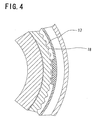
- Fig. 4 is an A-A1 arrow direction fragmentary sectional view in a rotary-vessel lower stop point of the invention;
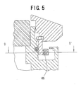
- Fig. 5 is a principal-structure fragmentary sectional view of a rotary-vessel upper stop point of the invention;
- Fig. 6 is a B-B1 arrow direction fragmentary sectional view in a rotary-vessel upper stop point of the invention;
- Fig. 7 is a plan view of a ring elastic member part of the invention; and
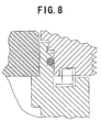
- Fig. 8 is a principal-structure fragmentary sectional view of a conventional rotary vessel.
-
- An embodiment of the present invention will be explained below with reference to the drawings.
- The present invention is structured, as shown in Fig. 1, by a degree-
contact step 11, apositioning groove 12 holding a positioningelastic member 5, a rotary vessel 1 having a gear-formed concave-convex portion 13 arbitrary divided relative to a planar form, a vessel degree-contact surface 26, acase barrel 2 having apositioning protrusion 25, a rotation-stop dowel 43 engaged in a rotation-stop hole 23, and a rotation regulatingring 4 having arotation regulating portion 41 corresponding to the gear-formed concave-convex portion 13 and fixed on thecase barrel 2. - Fig. 1 shows a state that a rotary-
vessel bottom surface 14 is in contact with a rotary-vessel receiving surface 21 of thecase barrel 2, the state of which is defined as a lower stop point. The rotary vessel 1 can stop at the lower stop point by the positioningelastic member 5 held by thepositioning groove 12 of the rotary vessel 1 and thepositioning protrusion 25 of thecase barrel 2. - The rotation regulating
ring 4 does not rotate due to the engagement of therotation stop dowel 43 possessed by therotation regulating ring 4 withrotation stop hole 23 in singular or plurality opened in thecase barrel 2. At this time, engagement is made between the gear-formed concave-convex portion 13 of the rotary vessel 1 and therotation regulating portion 41 of therotation regulating ring 4 fixed on thecase barrel 2, whereby the rotation vessel 1 is secured with stop stability and not rotated. - The
rotation regulating portion 41 of therotation regulating ring 4 fixed on thecase barrel 2 is provided singular or in plurality. - By the contact of the chatter preventing
elastic member 6 fitted in thefixing groove 24 of thecase barrel 2 with theelastic contact surface 15 of the rotary vessel 1, the rotary vessel 1 is further secured with stop stability. - Fig. 2 shows a state that, by putting the finger on the finger-putting
slant surface 16 to vertically move the rotary vessel, 1 the positioningelastic member 5 held by thepositioning groove 12 of the rotary vessel 1 is deflected and gotten over thepositioning protrusion 25 of thecase barrel 2. At this time, the positioningelastic member 5 held by thepositioning groove 12 of the rotary vessel 1 interferes with a protrusionupper surface 27 of thecase barrel 2, whereby the rotary vessel 1 is allowed to stop at the upper stop point. Thus, the rotary vessel 1 is allowed to rotate stably in the upper stop point. - In this state, the engagement between the gear-formed concave-
convex portion 13 of the rotary vessel 1 and therotation regulating portion 41 of therotation regulating ring 4 fixed on thecase barrel 2 is completely released to allow the rotary vessel 1 to rotate freely. - In order to prevent the
rotation regulating ring 4 fixed on thecase barrel 2 from moving together with the rotary vessel 1 to the upper stop point when the rotary vessel 1 is moved to the upper stop point, therotation regulating ring 4 has aremoval preventing protrusion 42. Due to the interference between theremoval preventing protrusion 42 of therotation regulating ring 4 and a circumferential grooveupper wall 22 of thecase barrel 2, therotation regulating ring 4 does not move to the upper stop point. - In the upper stop point, meshing is made between the gear
concave portion 17 of the gear-formed concave-convex portion 13 of the rotary vessel 1 and a detentelastic protrusion 45 provided in a detentelastic portion 44 of therotation regulating ring 4 fixed on thecase barrel 2. - When the rotary vessel 1 is rotated, the detent
elastic protrusion 45 provided in the detentelastic portion 44 of therotation regulating ring 4 radially moves due to a rotation force and intermittently interferes with the gear-formed concave-convex portion (13), providing a click feel to the rotary vessel 1. - The
rotation regulating portion 41 of therotation regulating ring 4 and the detentelastic protrusion 45 are alternately arranged with respect to a plane. - Also, the
rotation regulating portion 41 of therotation regulating ring 4 and the detentelastic protrusion 45 are arranged in upper and lower surfaces with respect to a direction of the plane. - The detent
elastic portion 44 of therotation regulating ring 4 and the detentelastic protrusion 45 are provided in a single or a plurality of positions. - In order to prevent the rotary vessel 1 from disengaging from the
case barrel 2 upon moving the rotary vessel 1 in the upper direction, the rotary vessel 1 has a degree-contact step 11 and thecase barrel 2 has a vessel degree-contact portion 26. - In this invention, as described above, a rotary vessel structure for a wristwatch case having a rotation function of the rotary vessel 1 different depending on a stop position was realized, wherein, when the rotary vessel 1 is positioned in the lower stop point, the gear-formed concave-
convex portion 13 engages therotation regulating portion 41 of therotation regulating ring 4 to prohibit the rotary vessel 1 from rotating, while, when the rotary vessel 1 is positioned in the upper stop point, the meshing is released between the gear-formed concave-convex portion 13 and therotation regulating portion 41 of therotation regulating ring 4 to allow the rotary vessel 1 to rotate freely. - As a result of this, stop stability and rotation operationality are both provided in the conventional rotary vessel structure having no vertical change of position. As a result, contrary to the current situation that the rotary vessel requires heavy rotation torque and concave-convex form is unavoidably required on a surface or peripheral portion of the rotary vessel to obtain sufficient rotation torque upon rotating the rotary vessel by the finger, a wristwatch case having a rotary vessel was realized assuring stop stability and rotation ability without the necessity of providing a concave-convex form on a surface or peripheral portion of the rotary vessel. Also, because the rotation torque can be minimized, no pain is felt in the finger during actuating rotation. Also, the design restriction of the rotary vessel requiring a concave-convex form is eliminated thus providing a great effect of increasing design freedom.
- As shown in Fig. 5, it is possible to provide a click feel to free rotation of the rotary vessel 1 by causing slight interference due to the gear-formed concave-
convex portion 13 and the detentelastic protrusion 45 provided in the detentelastic portion 44 in a state that the rotary vessel 1 is positioned in the upper stop point.
Claims (6)
- A wristwatch case having a rotary vessel comprising:a rotary vessel having a structure movable generally vertical with respect to a plane of a wristwatch case; anda rotation regulating ring having a rotation mechanism on a circumference different in rotation function of the rotation vessel at a plurality of stop points in a vertical movable range;wherein the rotation regulating ring is arranged between a rotary vessel and a case barrel.
- A wristwatch case having a rotary vessel comprising:a rotary vessel having a structure movable generally vertical with respect to a plane of a wristwatch case; anda positioning elastic member to stop the rotary vessel in each of a plurality of positions.
- A wristwatch case having a rotary vessel according to claim 1, wherein the rotation regulating ring is arbitrary divided in the circumference of the rotation regulating ring and planarly alternately arranged with a plurality of rotation mechanisms different in vessel rotation function.
- A wristwatch case having a rotary vessel according to claim 3, wherein the rotation regulating ring is planarly alternately arranged with. the plurality of rotation mechanisms different in vessel rotation function.
- A wristwatch case having a rotary vessel according to claim 1, further comprising:a gear-formed concave-convex portion formed in the rotation vessel; anda detent elastic protrusion to interfere with the gear-formed concave-convex portion, to radially move due to a rotation force on the gear-formed concave-convex portion to cause a click feel and to arrange the rotation regulating ring;wherein the click elastic protrusion causes a click feel by intermittently interfering with the gear-formed concave-convex portion.
- A wristwatch case having a rotary vessel according to claim 5, wherein the gear-formed concave-convex portion of the rotary vessel is formed to a planar form of the rotary vessel.
Applications Claiming Priority (2)
| Application Number | Priority Date | Filing Date | Title |
|---|---|---|---|
| JP2000093518 | 2000-03-30 | ||
| JP2000093518A JP3712911B2 (en) | 2000-03-30 | 2000-03-30 | Watch case with rotating bezel |
Publications (1)
| Publication Number | Publication Date |
|---|---|
| EP1139185A1 true EP1139185A1 (en) | 2001-10-04 |
Family
ID=18608695
Family Applications (1)
| Application Number | Title | Priority Date | Filing Date |
|---|---|---|---|
| EP01302498A Withdrawn EP1139185A1 (en) | 2000-03-30 | 2001-03-19 | Wristwatch case having a rotary vessel |
Country Status (3)
| Country | Link |
|---|---|
| US (1) | US6599009B2 (en) |
| EP (1) | EP1139185A1 (en) |
| JP (1) | JP3712911B2 (en) |
Cited By (5)
| Publication number | Priority date | Publication date | Assignee | Title |
|---|---|---|---|---|
| EP1431845A1 (en) * | 2002-12-20 | 2004-06-23 | Rolex S.A. | Watchcase |
| EP1669816A1 (en) * | 2004-12-08 | 2006-06-14 | Eterna SA | Diver's watch |
| EP1835363A1 (en) * | 2006-03-16 | 2007-09-19 | Officine Panerai Branch of Richemont International SA | Timepiece incorporating a rotary bezel |
| EP2672332A1 (en) * | 2012-06-06 | 2013-12-11 | Omega SA | Improved rotating bezel system |
| CN104460287A (en) * | 2013-09-20 | 2015-03-25 | 精工电子有限公司 | Timepiece |
Families Citing this family (18)
| Publication number | Priority date | Publication date | Assignee | Title |
|---|---|---|---|---|
| JP2003194968A (en) * | 2001-12-28 | 2003-07-09 | Seiko Instruments Inc | Rotary bezel device and portable watch using the same |
| JP4153378B2 (en) * | 2003-07-14 | 2008-09-24 | セイコーインスツル株式会社 | clock |
| JP4430389B2 (en) * | 2003-12-25 | 2010-03-10 | セイコーインスツル株式会社 | Cell phone clock |
| US7134784B1 (en) | 2003-12-31 | 2006-11-14 | James Marin | Rotating bezel watch |
| US7080938B1 (en) * | 2004-09-07 | 2006-07-25 | Quentin Moore | Watch apparatus |
| DE202005003029U1 (en) * | 2005-02-23 | 2005-10-27 | Damasko, Petra | Watch case and watch with such a case |
| JP4850008B2 (en) * | 2006-09-19 | 2012-01-11 | セイコーインスツル株式会社 | clock |
| US7490978B2 (en) * | 2006-09-21 | 2009-02-17 | Jacqueline Crisci | Analog wristwatch having a multi-bezel timing mechanism |
| US7682070B2 (en) * | 2007-08-31 | 2010-03-23 | Nike, Inc. | Timepiece with stabilizing bezel |
| JP5155904B2 (en) * | 2009-02-17 | 2013-03-06 | セイコーインスツル株式会社 | clock |
| USD715163S1 (en) * | 2012-02-27 | 2014-10-14 | Christian Dior Couture, S.A. | Watch |
| EP2672333A1 (en) * | 2012-06-06 | 2013-12-11 | Omega SA | Rotating bezel system |
| JP6741397B2 (en) * | 2014-02-10 | 2020-08-19 | ロレックス・ソシエテ・アノニムRolex Sa | Mobile watch side and watch |
| CH712740B1 (en) * | 2016-07-26 | 2020-08-31 | Omega Sa | Sub-assembly of a covering for a timepiece, in particular a watch, or for a piece of jewelry. |
| CH712742A2 (en) * | 2016-07-26 | 2018-01-31 | Omega Sa | Subset of clothing for a timepiece, in particular a watch, or for jewelery. |
| EP3582028A1 (en) * | 2018-06-13 | 2019-12-18 | Rolex Sa | Clock notching device |
| EP3796106B1 (en) | 2019-09-20 | 2022-06-01 | The Swatch Group Research and Development Ltd | Casing subassembly for a timepiece, watch or jewel |
| EP3796104B1 (en) * | 2019-09-20 | 2022-04-20 | The Swatch Group Research and Development Ltd | Casing subassembly for a timepiece, watch or jewel |
Citations (3)
| Publication number | Priority date | Publication date | Assignee | Title |
|---|---|---|---|---|
| CH503306A (en) * | 1968-08-22 | 1970-09-30 | Centrale S A Fab | Watch box |
| US4420264A (en) * | 1981-09-18 | 1983-12-13 | Citizen Watch Co., Ltd. | Structure for preventing the rotating of a register ring of a diver's watch |
| EP0436468A1 (en) * | 1990-01-03 | 1991-07-10 | Montres Rolex Sa | Watch case with a rotating bezel |
Family Cites Families (15)
| Publication number | Priority date | Publication date | Assignee | Title |
|---|---|---|---|---|
| JPS5061883U (en) * | 1973-10-03 | 1975-06-06 | ||
| JPS6029910B2 (en) * | 1978-05-30 | 1985-07-13 | セイコーインスツルメンツ株式会社 | Structure of watch case |
| JPS57166190U (en) * | 1981-04-14 | 1982-10-20 | ||
| JPH0672935B2 (en) * | 1985-12-24 | 1994-09-14 | シチズン時計株式会社 | Rotating bezel structure of watch |
| JPH0648460Y2 (en) * | 1988-08-17 | 1994-12-12 | シチズン時計株式会社 | Reverse rotation prevention register ring structure |
| CH676649B5 (en) * | 1988-11-25 | 1991-08-30 | Remy Montavon Sa | |
| JPH02133692U (en) * | 1989-04-11 | 1990-11-06 | ||
| EP0403717B1 (en) * | 1989-06-19 | 1993-08-04 | Roventa-Henex SA | Watch with a rotating bezel |
| JP3027840B2 (en) * | 1991-06-07 | 2000-04-04 | カシオ計算機株式会社 | Equipment case with rotating bezel |
| JP3124810B2 (en) * | 1992-01-10 | 2001-01-15 | シチズン時計株式会社 | Register ring holding structure |
| JPH06186355A (en) * | 1992-12-18 | 1994-07-08 | Casio Comput Co Ltd | Structure of rotary bezel |
| CH686470B5 (en) * | 1994-06-09 | 1996-10-15 | Rolex Montres | Box rotating bezel watch. |
| US5654941A (en) * | 1995-05-26 | 1997-08-05 | Walca Sa | Device for fastening a rotationally symmetrical part, in particular a rotatable ring, a back cover or a watch-glass to a watchcase |
| IT1285148B1 (en) * | 1996-06-03 | 1998-06-03 | Panerai Off Srl | DEVICE FOR LOCKING THE ROTATING BEZEL OF WATCHES, IN PARTICULAR DIVING WATCHES, AND FOR WATER-SEALING THE CROWN |
| US6379037B1 (en) * | 2000-03-15 | 2002-04-30 | Timex Group B.V. | Setting mechanism for a timepiece |
-
2000
- 2000-03-30 JP JP2000093518A patent/JP3712911B2/en not_active Expired - Lifetime
-
2001
- 2001-03-19 EP EP01302498A patent/EP1139185A1/en not_active Withdrawn
- 2001-03-28 US US09/819,478 patent/US6599009B2/en not_active Expired - Lifetime
Patent Citations (3)
| Publication number | Priority date | Publication date | Assignee | Title |
|---|---|---|---|---|
| CH503306A (en) * | 1968-08-22 | 1970-09-30 | Centrale S A Fab | Watch box |
| US4420264A (en) * | 1981-09-18 | 1983-12-13 | Citizen Watch Co., Ltd. | Structure for preventing the rotating of a register ring of a diver's watch |
| EP0436468A1 (en) * | 1990-01-03 | 1991-07-10 | Montres Rolex Sa | Watch case with a rotating bezel |
Cited By (13)
| Publication number | Priority date | Publication date | Assignee | Title |
|---|---|---|---|---|
| EP1431845A1 (en) * | 2002-12-20 | 2004-06-23 | Rolex S.A. | Watchcase |
| US6871997B2 (en) | 2002-12-20 | 2005-03-29 | Rolex S.A. | Watch case |
| US7635219B2 (en) | 2004-12-08 | 2009-12-22 | Eterna Sa Fabrique D'horlogerie | Diver's watch |
| WO2006061422A1 (en) * | 2004-12-08 | 2006-06-15 | Eterna Sa | Diver's watch |
| EP1669816A1 (en) * | 2004-12-08 | 2006-06-14 | Eterna SA | Diver's watch |
| RU2383047C2 (en) * | 2004-12-08 | 2010-02-27 | ЭТЕРНА СА Фабрик д хорлогери | Diver's watch |
| EP1835363A1 (en) * | 2006-03-16 | 2007-09-19 | Officine Panerai Branch of Richemont International SA | Timepiece incorporating a rotary bezel |
| WO2007105043A3 (en) * | 2006-03-16 | 2008-03-06 | Richemont Int Sa | Timepiece with rotating bezel |
| EP2672332A1 (en) * | 2012-06-06 | 2013-12-11 | Omega SA | Improved rotating bezel system |
| CN103472709A (en) * | 2012-06-06 | 2013-12-25 | 奥米加股份有限公司 | Improved rotating bezel system |
| US8777480B2 (en) | 2012-06-06 | 2014-07-15 | Omega S.A. | Rotating bezel system |
| KR101459230B1 (en) | 2012-06-06 | 2014-11-07 | 오메가쏘시에떼아노님 | Improved rotating bezel system |
| CN104460287A (en) * | 2013-09-20 | 2015-03-25 | 精工电子有限公司 | Timepiece |
Also Published As
| Publication number | Publication date |
|---|---|
| JP3712911B2 (en) | 2005-11-02 |
| JP2001281357A (en) | 2001-10-10 |
| US20010040840A1 (en) | 2001-11-15 |
| US6599009B2 (en) | 2003-07-29 |
Similar Documents
| Publication | Publication Date | Title |
|---|---|---|
| US20010040840A1 (en) | Wristwatch case having a rotary vessel | |
| EP1182521B1 (en) | Wristwatch case with rotary bezel | |
| US4225758A (en) | Switch operated axially or rotatably | |
| JP2004205515A (en) | Watch case | |
| JP2013160764A (en) | Watchcase with rotatable indexed bezel | |
| CA1106886A (en) | Rotatable electrical contact component with detent | |
| KR920021082A (en) | Shield plate attachment structure in helmet | |
| JP4353964B2 (en) | Combined operation type input device | |
| EP1139186B1 (en) | Wristwatch case | |
| JP3034210B2 (en) | Rotary switch | |
| US4843196A (en) | Mode switching device for an electrical switch | |
| JP2004185774A5 (en) | ||
| JP3249045B2 (en) | Camera release button mechanism | |
| JPH10340651A (en) | Moderation mechanism and rotary switch operating device having the mechanism | |
| JP2000298178A (en) | Portable watch case | |
| JP7788013B2 (en) | Rotational Braking Device | |
| JPH0814627B2 (en) | Register ring structure | |
| JP2007151682A (en) | Vehicle seat reclining device | |
| JPH0650203U (en) | Rotating electronic components | |
| US20050230229A1 (en) | Indexing mechanism | |
| JPH0117061Y2 (en) | ||
| JPH10326536A (en) | Knob for rotary electric controller and its mounting structure | |
| JPS6218502Y2 (en) | ||
| JPS6224849Y2 (en) | ||
| JPH0348555Y2 (en) |
Legal Events
| Date | Code | Title | Description |
|---|---|---|---|
| PUAI | Public reference made under article 153(3) epc to a published international application that has entered the european phase |
Free format text: ORIGINAL CODE: 0009012 |
|
| AK | Designated contracting states |
Kind code of ref document: A1 Designated state(s): AT BE CH CY DE DK ES FI FR GB GR IE IT LI LU MC NL PT SE TR |
|
| AX | Request for extension of the european patent |
Free format text: AL;LT;LV;MK;RO;SI |
|
| 17P | Request for examination filed |
Effective date: 20020307 |
|
| AKX | Designation fees paid |
Free format text: CH FR GB LI |
|
| REG | Reference to a national code |
Ref country code: DE Ref legal event code: 8566 |
|
| 17Q | First examination report despatched |
Effective date: 20050315 |
|
| STAA | Information on the status of an ep patent application or granted ep patent |
Free format text: STATUS: THE APPLICATION IS DEEMED TO BE WITHDRAWN |
|
| 18D | Application deemed to be withdrawn |
Effective date: 20050726 |