FIELD OF THE INVENTION
This invention relates to photographic materials. It particularly
relates to photographic base materials and the formation of a mechanically
assembled picture utilizing a brace.
BACKGROUND OF THE INVENTION
In the formation of color paper it is known that the base paper has
applied thereto a layer of polymer, typically polyethylene. This layer serves to
provide waterproofing to the paper, as well as providing a smooth surface on
which the photosensitive layers are formed. The formation of a suitably smooth
surface is difficult requiring great care and expense to ensure proper laydown and
cooling of the polyethylene layers. Such a smooth surface requires a great deal of
care and expense associated with chill rolls. There is a need for a photographic
color print material that has a polyethylene surface but does not require chill rolls
for the formation of a glossy surface.
In photographic papers the polyethylene layer also serves as a
carrier layer for titanium dioxide and other whitener materials as well as tint
materials. It would be desirable if the colorant materials rather than being
dispersed throughout the polyethylene layer could be concentrated nearer the
surface of the layer where they would be more effective photographically.
In the formation of photographic and other imaging elements it is
known in the art to coat or apply layers of polymer to or to laminate biaxially
oriented sheets of polymer to a base substrate such as paper or polyester. It is
further known in the art as disclosed in US Patent 4,355,099 to provide a silver
halide layer on a clear film, expose, develop, process and then to post laminate
using an adhesive to a light reflective base. While such a composite structure has
a number of advantages, it is very difficult and cumbersome to apply an adhesive,
cure it and then stick two webs together. There remains a need to provide an
imaging element with a thin protective polymer sheet with an image receiving
layer that can be attached to a reflective base without the use of expensive, messy
adhesive.
In US Patent 5,663,023 a two part system for xerography and ink is
disclosed. The first part provides a clear substrate with a reverse reading image
that is imaged and then joined with a reflective base that has been pre coated with
an adhesive. While this technique overcomes some of the difficulties of applying
an adhesive at the time of image formation by using a pre-coated substrate, there
are additional problems and difficulties with joining the two substrates without
creases. Furthermore even pre-coated adhesives a still messy and may
contaminate the work area and render the image useless because of the
contamination problems. There remains a need to provide an imaging element
with thin clear polymer over the image that can be attached to a reflective or even
transparent base without the use of expensive, messy adhesives.
In US Patent 5,866,282 it is proposed to attach sheets of biaxially
oriented polymer to a base substrate for photographic use, and in US Patent
5,888,714 it is proposed to use an adhesive such as metallocene catalyzed ethylene
plastomers for bonding biaxially oriented polyolefin sheets. Both these inventions
provide excellent print materials and are able to adhere the biaxially oriented
sheets to the base substrate. The base substrate provides sufficient stiffness to the
support for conveyance through the various coating and processing machines.
One drawback of this system is the expense of having to adhere polymer sheets to
a base substrate and then carry the added weight and thickness throughout the
manufacturing and photofinishing process. The added thickness put limitations on
the length of rolls requires frequent roll changes, which results in added waste and
expense. There remains a need to provide a substantially thin imaging support
that does not require it to be adhered to a thick base substrate.
Photographic materials have been known for use as prints for
preserving memories for special events such as birthdays and vacations. They
also have been utilized for large display materials utilized in advertising. These
materials have been known as high quality products that are costly and somewhat
delicate, as they would be easily defaced by abrasion, water, or bending.
Photographs are traditionally placed in frames and photo albums in view of their
fragile and delicate nature, as well as their value. They are considered luxury
items for the consumers to preserve a record of important events in their lives.
Photo albums and picture frames do not allow prints to be handled and viewed in a
convenient or friendly manner. There remains a need to provide a convenient and
friendly format for images to be shared with a number of people without fear of
irreversible damage.
Prior art photographic reflective materials typically contain
cellulose fiber paper to provide support for the imaging layers. While paper is an
acceptable support for the imaging layers, providing a perceptually preferred feel
and look to the photograph, paper does present a number of manufacturing
problems which reduce the efficiency at which photographic paper can be
manufactured. Problems include those such as processing chemistry penetration
into the edges of the paper, paper dust as photographic paper is slit, punched and
chopped, and as loss of emulsion hardening efficiency because of the moisture
gradient that exists between the photographic emulsion and the paper. It would be
desirable if a reflective image could be formed without the use of cellulose paper.
In reflective photographic papers there is a need to protect the
imaging layers from scratches, fingerprints, and stains. Current photographic
reflective papers use a gelatin overcoat to protect the imaging layers. While the
gelatin does provide some level of protection, it can easily be scratched reducing
the quality of the image. Further, fingerprints or stains caused by common
household liquids such as coffee, water, or fruit juice can easily stain and distort
images. Wiping the images while wet causes undesirable distortion to the gelatin
overcoat. Post photographic processing equipment exists that provides a
protective coating to the imaging layers. Typically consumer images are
individually coated or laminated with a polymer to provide protection to the image
layers. A common example is photographic identification badges that are
typically laminated with a clear polymer sheet to provide protection to the image
on the identification badge. Post processing application of a protective layer is
expensive, as it requires an additional step in the preparation of the reflective print
and additional materials to provide the overcoat. It would be desirable if a
reflective photographic image could be formed with a protective coating over the
developed image layers that could be efficiently applied.
Typically, photographic reflective imaging layers are coated on a
polyethylene coated cellulose paper. While polyethylene coated cellulose paper
does provide an acceptable support for the imaging layers, there is a need for
alternate support materials such as polyester or fabric. The problem with
alternate, nonpaper supports is the lack of robustness in photographic processing
equipment to mechanical property changes in supports. The photographic
processing equipment will not run photographic materials that have significantly
different mechanical properties than prior art photographic materials. It would be
desirable if a reflective photographic image could be efficiently formed on
alternate supports.
In the consumer industry materials are placed in packages as a
means of protection or preserving the quality of the delicate products.
Photographs and images are a very delicate product but are not traditional
protected from handling damage, spills, fingerprints and other abuses. In some
application the image may be overlaminated with a clear polymer sheet, but once
again, the overlaminate sheet must be adhesive coated prior to application to the
image. These overlaminates create problems with curl and torsional strain on the
image structure that render them undesirable. There remains a need to provide a
print with protection without curl and other problems.
PROBLEM TO BE SOLVED BY THE INVENTION
Photographic images are typically produced on a thick polymer
coated paper base. The paper base used for photographic prints is very expensive
and must be very pure and free of materials that are photoactive and resistant to
photo processing chemicals. There remains a need for a photographic print
material that is not limited by these and other design limitations.
SUMMARY OF THE INVENTION
It is an object of the invention to provide improved imaging
elements.
It is another object to provide an imaging element that does not
need to be adhered to a thick base.
It is a further object to provide images that are not easily damaged.
It is an additional object of this invention to provide an image that
is sealed from the environment.
These and other objects of the invention are accomplished by a
mechanically assembled picture comprising at least one image element comprising
an image on a thin polymer sheet, a brace, and a transparent polymer sheet
overlaying said image and brace, wherein said transparent sheet mechanically
holds said image to said brace.
ADVANTAGEOUS EFFECT OF THE INVENTION
The invention provides improved image protection. The invention
includes a means to join a base substrate to an image without environmental
protection without the use of expensive and messy adhesives. This invention
provides an imaging element with a brace that makes a pleasing image for the
consumer.
BRIEF DESCRIPTION OF THE DRAWINGS
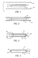
Fig. 1 is a schematic of the unassembled imaging member of the
invention.
Fig. 2, Fig. 3, and Fig. 4 illustrate the assembly and sealing of the
imaging element of the invention.
DETAILED DESCRIPTION OF THE INVENTION
The invention has numerous advantages over prior practices in the
art. Current imaging elements have a light sensitive silver halide layer, or a dye
receiving layer for ink jet or thermal imaging applications or perhaps have toner
deposited on a surface to form an image or text. All these elements typically
consist of a surface layer with a more substantial base that provides support to the
image. Typically the bases are white, reflective and thick, or in some cases
transparent. Whatever the configuration they have a substantially thick support
that is a critical part of the imaging element for handling and feel. Furthermore the
base is the platform that supports the image. The imaging element of this
invention may have either a thin reflective imaging carrying layer or a thin
transparent image carrying layer. Since the carrying layer may be a thin polymer
sheet, larger rolls of material may be used throughout the manufacturing
operations as well as in photofinishing or printing. Larger rolls are important in
minimizing cost associated with roll to roll transfers that create waste on each roll
change. Smaller rolls also result in more frequent changes, which consume
operator time.
The utilization of the thin, flexible, and tough silver halide
materials results in an imaging element having many superior properties. These
elements are bright, sharp, and high in color as well as having resistance to
abrasions, spills, scratches, fingerprints and other handling related damage. The
imaging elements of this invention have a depth of image unsurpassed by existing
materials. The imaging elements of the invention while having the advantage of
superior image are available on thin base materials that are low in cost while
providing superior opacity and strength.
The terms as used herein, "top", "upper", "emulsion side", and
"face" mean the side or toward the side of a photographic packaging label bearing
the imaging layers. The term environmental protection layer means the layer
applied to the post processed imaging layers. The terms "face stock" and
"substrate" mean the material to which the silver halide layers are applied. The
terms "bottom", "lower side", "liner" and "back" mean the side or toward the side
of the photographic label or photographic packaging material opposite from the
side bearing the photosensitive imaging layers or developed image. The term
"brace" refers to stiffening material that is brought into contact with the imaged
thin polymer sheet. The brace provides an important function. It provides
substantial thickness and stiffness to a thin imaged polymer sheet and provides the
viewer with a comfortable tactile feel when handling the imaged print. In general
it is used to support the image and the carrying polymer layer. Typical brace
materials may be paper, cardboard, foam backing board, wood, metal, metallized
substrates, textile, cloth, other plastics. They may be substantially opaque or
transparent and may either be smooth or rough. The brace material may also be
any shape because the imaged transparent polymer sheet may be made to conform
to most any shape or physical configuration and is held mechanically to the brace
by a transparent sheet. The term picture refers to an image or text and image. The
image may be made with photosensitive silver halide, photographic dyes, ink jet,
thermal dye sublimation or electrophotographic.
The imaging element of this invention has the ability to be joined
with any substrate without regard to having an adhesive to hold the image in
contact with the supporting member. Figs. 1-4 show the basic steps to incorporate
a picture in a sealed package without the use of adhesives. Fig. 1 illustrates the
individual components needed for a mechanically assembled picture. The
transparent polymer sheet 10 of said invention which overlays the said imaging
element 12 on the topside and by transparent sheet 16 which overlays the brace 14
from the bottom side. It is below the brace. The imaging element 12 comprises
the image layer 11 and a base thin polymer sheet 13. Fig. 2 is a representation of
the individual components having been placed together and not held together other
than by their own weight. The transparent polymer sheet 10 is physical touching
the imaging element 12 which is physical touching the brace 14 which is
physically touching the bottom transparent polymer sheet 16. It should be noted
in Fig. 2 that the transparent polymer sheets 10 and 16 extend beyond the edges of
the imaging element 12 and the brace 14.
In Fig. 3 one edge of the top and bottom transparent polymer sheets
10 and 16 is brought together and sealed 28 over the edge of the imaging element
12 and the brace 14 while a vacuum 36 is applied. The vacuum helps to pull the
air out of the package and between the layers so that there is intimate contact
between the layers. Fig. 4 is the completed mechanically assembled picture
wherein transparent polymer sheets 10 and 16 have been sealed on each edge 28
and 38. Having been vacuum evacuated and sealed, the transparent polymer sheet
10 and 16 holds the imaging element 12 to the brace 14.
The supporting brace is brought into contact with the thin imaged
polymer sheet, cut and then mechanically assembled and held in place using a
transparent sheet. The actual cutting of the thin polymer sheet and brace may be
done simultaneously, in which the brace provides substantial support during the
cutting/chopping action. The cutting and chopping of the brace and thin imaged
polymer sheet may also be done in separate steps and then the two cut parts are
then brought into the proper configuration and a thin transparent sheet is applied
to mechanically hold the parts together. In this manner the assembled picture is
mechanically held together without the need for expensive, messy adhesives.
Adhesive are not preferred because them then to yellow with time and are not also
stable to ultraviolet light over time. Some adhesives are not fully cured or cross-linked
resulting in dimensional changes and chemical out gassing. Some of these
gases may interact with the imaging dyes or silver in the case of black and white
photographs and result in their degradation.
A preferred embodiment of this invention is a mechanically
assembled picture that has an image on a thin polymer sheet, a brace and a
transparent polymer sheet overlaying the brace and the imaged thin polymer sheet.
The overlaying transparent polymer sheet mechanically holds the image to the
brace. In an additional embodiment the overlaying transparent polymer sheet
covers both the top and bottom surfaces and edges of said assembled picture. The
transparent polymer sheet is shrunk to mechanically hold the image and brace.
An additional embodiment of this invention provides a polymer
sheet bag that is sealed to mechanically hold the image and brace. In a further
embodiment a vacuum is applied to the bag prior to sealing. The vacuum helps to
assure that there is good optical contact between the imaged polymer sheet and
brace. Since there may be some remaining gases inside the sealed bag, the bag
containing the imaged polymer sheet and brace may be purged with an inert gas
prior to having the vacuum applied. In the case of some brace material such as
paper, textiles or cardboard any air pockets in the brace are filled with the inert
gas. This is important when the image dyes, pigments and other chemistry in the
imaging layer is sensitive to oxygen. The inert gases may either pure gases or
mixtures of gases such as nitrogen, argon, helium, carbon dioxide or other suitable
gas. The mechanically assembled picture may use a transparent bag that is sealed
and shrunk after drawing a vacuum.
The transparent polymer sheet of this invention preferably has an
oxygen transmission rate of less than 8.0 cc/m2 hr. atm. oxygen transmission rate.
This may be achieved by the polymer selection or by a layer on the top or bottom
side of said transparent polymer sheet or may be an integral part of the transparent
polymer. Said oxygen barrier may be selected from the group consisting of an
oxygen barrier layer having less than 8.0 cc/m2 hr. atm. oxygen transmission rate.
The oxygen barrier may be incorporated as a layer into the said transparent
polymer sheet that overlays the image and brace through co-extrusion prior to
biaxial orientation. Said oxygen impermeable layer comprises at least one
member selected from the group consisting of homo- and co-polymers of
acrylonitrile, alkyl acrylates such as methyl acrylate, ethyl acrylate, butyl acrylate,
alkyl methacrylates such as ethyl methacrylate and methyl methacrylate,
methacrylonitrile, alkyl vinyl esters such as vinyl acetate, vinyl propionate, vinyl
ethyl butyrate and vinyl phenyl acetate, alkyl vinyl ethers such as methyl vinyl
ether, butyl vinyl ether, chloroethyl vinyl ether, vinyl alcohol, vinyl chloride,
vinylidene chloride, vinyl fluoride, styrene and vinyl acetate (in the case of
copolymers, ethylene and/or propylene can be used as comonomers), cellulose
acetates such as diacetyl cellulose and triacetyl cellulose, polyesters such as
polyethylene terephthalate, a fluorine resin, polyamide (nylon), polycarbonate,
polysaccharide, aliphatic polyketone, blue dextran, and cellophane. The said
oxygen barrier layer would preferably be located in the sheet structure at the
interface between the said transparent polymer sheet and the image layers on the
top side and the brace on the bottom side. This location would have minimal
effect on the overall image quality while positively impacting image stability.
Two preferred barrier layer materials for this structure are 1) an aliphatic
polyketone polymer and 2) a copolymer of vinyl alcohol and ethylene whereby the
second is most preferred because they are low in cost and effective oxygen
barriers. These materials possess very low oxygen transmission rates and can be
extruded through multilayer coextrusion equipment with minimal modifications to
the process. The thickness of the oxygen barrier layer of this invention is not
critical, provided that the oxygen permeability is not more than 8.0 cc/m2 hr. atm.
oxygen transmission rate, and more preferably not more than 2.0 m2. hr. atm.
oxygen transmission rate, as this level appears to provide a good balance between
material cost and benefits of use. The preferred barrier layer material is a
copolymer of vinyl alcohol and ethylene and is incorporated into the transparent
polymer sheet prior to orientation through coextrusion. A second method of
incorporating an oxygen barrier layer having less than 8.0 cc/m2. hr. atm. oxygen
transmission rate is to apply the layer as a post extrusion coated layer onto the said
transparent sheet. This post extrusion layer comprises at least one member
selected from the group consisting of polyvinyl alcohols, polyvinylidene
chlorides, aliphatic polyketones, chemically hardened gelatin, and mixtures
thereof. Liquid coating methods which can be used according to the invention
include a method in which a polymer is dissolved in water or an organic solvent,
uniformly coated on the transparent polymer sheet, and dried by hot air, and a
method in which a polymer emulsion is coated and then dried. These application
techniques are generally known in the industry. In the preferred form, the post
extrusion layer comprises a layer of polyvinyl alcohol, which is applied to the
sheet as an aqueous coating. Aqueous coated polyvinyl alcohol has a very low
oxygen transmission rate and can be produced to have no detrimental effect on
silver halide imaging technology.
The control of water vapor transmission can be provided by the
transparent polymer sheet or the imaged thin polymer sheet. In the preferred
embodiment the transparent sheet of the mechanically assembled picture has a
water vapor transmission rate of less than 0.85 x 10⁻⁵ g/mm2/day. With the
incorporation of other layer(s) that are integrally formed with, applied to or
bonded with the transparent polymer sheet or the imaged thin polymer sheet, the
water vapor transmission rate can be adjusted to achieve the desired photographic
or imaging results. One or more of the layers comprising the thin imaged polymer
sheet may contain TiO2 or other inorganic pigment. In addition one or more of the
layers comprising the thin imaged polymer sheet may be voided. Other materials
that can be used to enhance the water vapor transmission characteristics comprise
at least one material from the group consisting of polyethylene terephthalate,
polybutylterephthalate, acetates, cellophane polycarbonates, polyethylene vinyl
acetate, ethylene vinyl acetate, methacrylate, polyethylene methylacrylate,
acrylates, acrylonitrile, polyester ketone, polyethylene acrylic acid,
polychlorotrifluoroethylene, polychlorotrifluoroethylene, polytetrafluoroethylene,
amorphous nylon, polyhydroxyamide ether, and metal salt of ethylene methacrylic
acid copolymers.
Another method of reducing the water vapor transmission rate of
either the thin imaged polymer sheet or the transparent polymer sheet overlaying
the image and brace is to coat a layer of low vapor transmission material that has
been dispersed or mixed in either an organic or aqueous solvent by any method
known in the art such as roller, gravure, curtain, or bead coating. In the
production of a suitable layer having low moisture transmission rates, preferably
hydrophobic water-insoluble synthetic polymers are used. These polymers are
applied as a coating from a solution in an organic solvent or mixture of solvents.
Preferred examples of such polymers include addition-type polymers and
interpolymers prepared from ethylenically unsaturated monomers which include
acrylates and methacrylates such as methyl acrylate, ethyl acrylate, butyl acrylate,
hexyl acrylate, n-octyl acrylate, 2-ethylhexyl acrylate, nonyl acrylate, benzyl
acrylate, lauryl acrylate, methyl methacrylate, ethyl methacrylate, butyl
methcrylate, hexyl methacrylate, n-octyl methacrylate, 2-ethylhexyl methacrylate,
nonyl methacrylate, benzyl methacrylate, lauryl methacrylate, dialkyl itaconates,
dialkyl maleates, acrylonitrile and methacrylonitrile, styrenes including substituted
styrenes, vinyl acetates, vinyl ethers, vinyl and vinylidene halides, and olefins
such as butadiene and isoprene. Other polymers that may be effectively employed
for the purpose of the present invention include organic solvent soluble
condensation polymers such as cellulose derivatives, including cellulose nitrate,
cellulose acetate, cellulose acetate proprionate, cellulose acetate butyrate, and the
like, polycarbonates, polyurethanes, polyesters, epoxies, and polyamides.
A second means to achieve the desired water vapor transmission
rate is the use of hydrophobic polymers coated on the transparent polymer sheet or
the thin imaged polymer sheet from an aqueous dispersion or latex by any method
known in the art. When applied to the thin polymer sheet overlaying the image
and brace said layer should be transparent but if applied to the thin imaged
polymer sheet it may be either transparent or opaque. Preferred examples of
particularly suitable aqueous dispersions include water dispersible polyurethanes
and polyesters. Examples of suitable latex polymers include addition-type
polymers and interpolymers prepared from the above mentioned ethylenically
unsaturated monomers. The latex polymers may be prepared by conventional
emulsion polymerization methods. The latex polymers may be core-shell
polymers as described in U.S. Patent 4,497,917.
The hydrophobic polymers which are applied from organic solvent
or aqueous media may contain reactive functional groups capable of forming
covalent bonds by intermolecular cross-linking or by reaction with a cross-linking
agent (i.e., a hardener). Suitable reactive functional groups include hydroxyl,
carboxyl, carbodiimide, amino, amide, allyl, epoxide, aziridine, vinyl sulfone,
sulfinic acid, and active methylene.
Said material can be selected and coated or otherwise applied to the
sheet in an amount to provide the desired water vapor barrier. The preferred
material for the thin imaged polymer sheet is a biaxially oriented polyolefin sheet
that is coated with high barrier polyvinylidene chloride in a range of coverage 1.5
to 6.2 g/m2. Polyvinyl alcohol can also be used but is less effective under high
relative humidity conditions. Through the use of at least one of these materials in
combination with a biaxially oriented sheet and a polymer tie layer, it has been
shown that improved rates of emulsion hardening can be achieved. The preferred
material for the transparent polymer sheet is a non-oriented polymer sheet that is
coated with high barrier polyvinylidene chloride in a range of coverage 1.5 to 6.2
g/m2.
A barrier layer to control the rate of water vapor transmission can
also be achieved by the use of a metal foil layer laminated to a brace or metallized
layer(s) coated or otherwise applied to the brace. The sheets of metal foil can be
attached to the brace with the use of a melt polymer or adhesive coating. In the
case in which the metal layer(s) are applied under the photo sensitive or imaging
layer(s), a layer of polyethylene was applied to provide for better adhesion of the
photo imaging layer to the base. In the case in which the metallized layer is
incorporated with the biaxially oriented sheet of polypropylene that serves as the
or part of the brace or as the thin imaged polymer sheet, the metallized layer is
vacuum deposited on the thin imaged polymer sheet. The metal or metallized
layer can comprise at least one material from the following list of aluminum,
nickel, steel, gold, zinc, copper, titanium, metallic alloys as well as inorganic
compounds such as silicon oxides, silicon nitrides, aluminum oxides or titanium
oxides. The preferred material comprises a vacuum deposited layer of aluminum
and one or more layers of polyolefin. This material has a water vapor
transmission rate of less than 0.85 x 10⁻⁵ g/m2/day. The prior art for use of a
metallized layer with films of polypropylene and coating of other substances to
control water vapor transmission is noted in US Patent No. 5,192,620. The
indicated use is for packaging applications.
In a preferred embodiment of this invention, the mechanically
assembled picture has a polyolefin transparent sheet that is shrunk and overlays
the image and brace. Said transparent polyolefin may have varying degrees of
orientation or annealing. Control of these properties is critical to control the
amount of dimensional change during the shrinking process. High levels of
shrinkage may apply excessive stress on the mechanically assembled picture. The
level of stress or force after shrinking may require that thicker and stiffer brace
materials be used. Polyolefins and copolymers of polyolefin are preferred because
they are low in cost and provide good protection. When additional durability is
needed for scratch resistance, minimizing fingerprints and improving overall
tearability properties; polyester sheets are preferred. In general polyester and
copolyesters are more durable. A further advantage is that polyesters are higher in
modulus may provide greater stiffness than other polymers. In a further
embodiment of this invention the transparent polymer sheet that is shrunk to the
thin imaged polymer sheet and brace is a polyamide sheet. Polyamides are
preferred in some cases because they have a unique feel and durability.
Furthermore the desire to control the oxygen and water vapor transmission rates in
the final mechanical assembled picture may influence the decision to use
polyamides. When the ultimate in durability for scratch resistant is desired a
polycarbonate sheet may be used.
Whether a polyolefin, polyester, polyamide, polycarbonate, vinyls
or other transparent polymer sheet is used, additional properties may be desirable.
Typically one customer dissatisifer is fingerprints. Polymer sheets by themselves
provide some added degree of wipeability over conventional imaged materials
particular for fingerprints and spills. The incorporation of matte particles into the
polymer sheet or in a layer on the polymer sheet is highly desirable to minimize
fingerprinting. The irregular surface reduces the contact area for fingerprints and
makes them less visible and certain matting materials will help to absorb the
fingerprint oils, therefore making them less objectionable. In addition to matte
particles, the surface of the transparent film may be roughened by mechanical
embossing when the polymer sheet is cast or may be roughen prior to or after it is
assembled with the brace and thin imaged polymer sheet. A further means of
achieving a rough or matte appearing in the transparent polymer sheet is to utilize
a mixture or blend of dissimilar polymers. In a further embodiment of this
invention the transparent polymer sheet overlaying said image and brace may
further comprise ultraviolet absorbers. Ultraviolet energy can break polymer
bonds, react with residual monomer or catalyst or other materials to form
hydroperoixdes or carbonyl groups. Any ultraviolet absorber may be used.
Typical ones include hydroxybenzophenones, hydroxyphenyl benzotriazoles,
hindered amine light stabilizers, metallic salts, pigments such as TiO2, ZnO. Since
the polymer sheet of this invention is transparent, pigments are not desirable. In
addition to ultraviolet absorbers, the polymer sheets may also contain a variety of
additives. These include antioxidants, tinting compounds such as blue and red
colorants, optical brighteners, antiblocks, and slip agents. When the polymer
sheet comprises a white pigment and wherein at least one layer may contain
polyolefin and, in particular, polypropylene further comprising a white pigment
such as TiO2, the layer may contain any of the hindered phenol primary
antioxidants commonly used for thermal stabilization of polypropylene, alone or
in combination with a secondary antioxidants. Examples of hindered phenol
primary antioxidants include benzenepropanoic acid, 3,5-bis(1,1-dimethylethyl)-4-hydroxy-,
2,2-bis[[3-[3,5-bis(1,1-dimethylethyl)-4-hydroxyphenyl]-1-oxopropoxy]methyl]-1,3-propanediyl
ester (such as Irganox 1010),
benzenepropanoic acid, 3,5-bis(1,1-dimethylethyl)-4-hydroxy-, octadecyl ester
(such as Irganox 1076), (such as Irganox 1035), phenol, 4,4',4"-[(2,4,6-trimethyl-1,3,5-benzenetriyl)tris(methylene)]tris[2,6-bis(1,1-dimethylethyl)
(such as Irganox
1330), but are not limited to these examples. Secondary antioxidants include
organic alkyl and aryl phosphites including examples such as Phosphorous acid,
bis[2,4-bis(1,1-dimethylethyl)-6-methylphenyl] ethyl ester (such as Irgafos 38),
ethanamine, 2-[[2,4,8,10-tetrakis(1,1-dimethylethyl)dibenzo[d,f][1,3,2]-dioxaphosphepin-6-yl]oxy]-N,N-bis[2-[[2,4,8,10-tetrakis(1,1-dimethylethyl)dibenzo[d,f][1,3,2]dioxaphosphepin-6-yl]oxy]ethyl]
(such as
Irgafos 12), phenol, 2,4-bis(1,1-dimethylethyl), phosphite (such as Irgafos 168).
A preferred embodiment uses Irgafos 168.
In the formation of an assembled picture, a preferred embodiment
is that the transparent sheet overlaying the image and brace has a modulus of 350
MPa. A transparent sheet of this modulus is important to assure that the
completed picture has acceptable stiffness and that the transparent sheet is
sufficiently tough to be assembled with the image and the brace. Higher modulus
sheets will help hold the individual elements together better and are better able to
withstand handling abuses. An additional embodiment in this invention
incorporates a bag as the transparent polymer sheet. In this preferred embodiment
a preformed bag allows for quick filling of said bag with the imaged print and then
pulling a vacuum in the bag and sealing it. A further embodiment then heat
shrinks the bag to assure a tight fit. An additional embodiment utilizes a
transparent polymer sheet or a transparent polymer bag with a roughness of at
least 0.3 micrometers at a spatial frequency of at least 5 micrometers or greater on
at least one side. Such a roughness provides a different and unique feel. The
roughness may be matched to that of traditional photographic paper to provide a
textured or matte appearing assembled picture. This not only provides a print that
reduces gloss, but also aids in the process of filling the bags by reducing the
coefficient of friction. It is preferred to have the roughness on the outer side of the
bag or polymer sheet. This outer and front location is preferred because it
provides a print with reduced fingerprint propensity, as well as reducing excessive
glossy. In high speed packaging applications of prints, it may also be desirable to
have some degree of roughness associated with the back side. This is desirable to
minimize scratches and to optimize the backside coefficient of friction to prevent
jams in the packaging equipment and assure good stacking. In some cases the
roughness can be in the sheet or bag prior to filling, sealing, evacuating, and or
shrinking. Additional variation of this is to have the roughness in either or both
the image element and brace. When the transparent polymer sheet or bag is heat
shrunk the texture pattern with show through. In most of these cases the polymer
sheet still has high gloss sheen associated to it. A further embodiment comprises a
substantially transparent sheet or bag with a gloss-reducing layer. Such a layer
may include light scattering materials such as silica, silca gels, sol gels, glass
beads, polymeric beads, pigments, and voids. A mixture of immesible polymers
may also be used to create a roughened surface with minimal sheen. Typically
polymer that may be used as the binder include vinyl, vinyl alcohol, vinyl acetates
copolymer, vinyl chloride copolymers, vinylidene chloride, cellulose triacetate,
cellulose propionate, polystyrene, polystyrene copolymers,
styrenebutylmethacrylate copolymers, styrene-allyl alcohol copolymers, gelatin,
polyester and copolyesters, vinyl pyridine and other derivatives, acrylates and
copolymers of acrylates such as but nor exclusive to poly(methylmethacrylate),
poly(ethyl methacrylate), polyamides resin, polysulfones, aromatic ester carbonate
copolymers, polycarbonates, methylstyrene-dimethylsiloxane block copolymers,
dimethyl siloxane-bisphenol copolymers and mixtures thereof.
Another preferred embodiment of this invention comprises a
transparent polymer bag that further comprises a tab. The tab may have holes that
are precut or punched to be accepted rings or other fastening devices such that the
mechanically assembled picture can then placed into a photoalbum or notebook.
In an additional embodiment of this invention the brace should be
substantially opaque to prevent show through and may further have a white
surface in contact with the image element. The white brace provides a good
reflective background when viewing the image. In the embodiment where the thin
imaged polymer sheet is also white and opaque, the brace material may be
transparent. This provides additional options for the selection of the brace
material. It would be possible to use a brown or unbleached kraft brace and still
have a pleasing white reflective picture. This is important because lower cost
materials may be used. Optional filler materials is selected from the group
consisting of titanium dioxide, colloidal silica, barium sulfate, zinc sulfide,
hydrated alumina, calcium silicate, calcium carbonate, zirconium oxide, blends of
filler as well as microspheres.
In this invention the brace material may have a stiffness of at least
150 Newtons. Such stiffness provides a strong brace that will resist the force of
the transparent polymer sheet once it has been shrunk. In an additional
embodiment of this invention, the mechanically assembled picture has a stiffness
of greater than 150 millinewtons. Most photographic and other imaging materials
have a unique feel to them. Most customers perceive superior print quality, with
substantial stiffness and feel. It is therefore an important aspect of this invention
to provide a mechanical assembled picture with adequate stiffness.
Another embodiment of a mechanically assembled picture
comprises a brace and/or transparent polymer sheet that further comprises a
fragrance. The fragrance material is selected from the group consisting of:
isoamylacetate, ethyl2-methyl butyrate, n-hexanal, damascenone, muscone,
ethylene brssylate, ethylenedodecanedioate, eremophilone, anethole, isobutyl-2-butenedioate,
2.5-dimethyl-4-hydroxy-3 (2H)-furanone, carvone, benzaldehyde,
tilylaldehyde, bezzylacetate, 5-methyl-2-phenyl-2-hexenal, iso amyl butyrate,
vanilin, isoamyl phenylacetate, furfurylmercaptan, furfuryl thioprop-ionate,
α-nonalactone, 2-methoxy-5-methyl pyrazine, cinnamic aldehyde,
ethyloenanthate, 2-methyl-2-pentenoic acid, methylanthranilate, ethyl 3-hydroxybutyrate,
nootktone, methyl (methylthio) pyrazine, bezylatacetate, indole,
citral, α-terpineol, β-sinensal, ethyl anthranilate, thymol, octylaldehyde, decyl
aldehyde, 2-methyl-3-92-tolypropionaldehyde, hydroxy citronella dimethyl 2-phenylpropionaldehyde,
2-methyl-3-(4-isoproylphenyl) propionaldehyde, 3-methyl-1,2-cyclopentanedione,
menthol, 3-methylthio-1,2-hexanol, a-undeca
lactone, 6-amyl-60-pyrone, 2,5-dimethylpyrazine, ethyidecane-cis-4-trans-2-thiopropionate,
allyl cyclohexane propionate, 6-methyl-60-ionone, trans-60-ionone,
4-(4-hydroxyphenyl)-2-butanone, ethylmaltol, methylcinnamate, 4-hydroxy-2,5-dimethyl-3(2H)-furanone,
ethymethyphenylglycidate, ethylvanilin,
propenyl quathol and mixtures thereof. Said fragrance may be applied to the
transparent polymer layer, the brace or to the imaged thin polymer sheet.
A further embodiment of this invention in which a mechanical
assembled picture has at least one imaging element with an image on a thin
polymer sheet and a brace with a transparent sheet mechanically holding the
image and brace may further contain a desiccant. The desiccant material may be
any material that absorbs or holds water in its structure. Typical desiccants are
hydroscopic substances such as activated alumia, calcium chloride, silica gel, zinc
chloride, microporous materials composed either aluminia silicates, chemically
similar to clays and feldspars, zeolites or crystalline aluminophosphates derived
from mixtures containing an organic amine or quaternary ammonium salts. The
microporous material should have a pore size from 5 to 10 angstroms to help
optimize the absorption of water.
One preferred embodiment of this invention has a brace that
contains cellulose fiber. The brace may be photographic paper, plain paper,
coated paper, polymer coated paper, kraft paper, non-woven cellulose, cardboard,
wood, wood derivatives or other materials. In further embodiment of this
invention the brace may comprise a voided polymer sheet. Such a sheet may
include but is not exclusive to biaxially oriented polymer sheets of polyolefins,
polyesters, polyamindes, polycarbonates, polystryene. Such sheets may further
contain layers of similar or dissimilar polymers that further comprise pigments
and other additives. In the case where the voided sheet is a polyolefin, any
suitable biaxially oriented polymer sheet may be used. Microvoided composite
biaxially oriented sheets are preferred and are conveniently manufactured by
coextrusion of the core and surface layers, followed by biaxial orientation,
whereby voids are formed around void-initiating material contained in the core
layer. Such composite sheets are disclosed in, for example, U.S. Patent Nos.
4,377,616; 4,758,462 and 4,632,869.
The core of the preferred composite sheet should be from 15 to
95% of the total thickness of the sheet, preferably from 30 to 85% of the total
thickness. The nonvoided skin(s) should thus be from 5 to 85% of the sheet,
preferably from 15 to 70% of the thickness.
The density (specific gravity) of the composite sheet, expressed in
terms of "percent of solid density" is calculated as follows:
Composite Sheet DensityPolymer Density x 100= % of Solid Density
Percent solid density should be between 45% and 100%, preferably between 67%
and 100%. As the percent solid density becomes less than 67%, the composite
sheet becomes less manufacturable due to a drop in tensile strength and it
becomes more susceptible to physical damage.
"Void" is used herein to mean devoid of added solid and liquid
matter, although it is likely the "voids" contain gas. The void-initiating particles
which remain in the finished packaging sheet core should be from 0.1 to 10 µm in
diameter, preferably round in shape, to produce voids of the desired shape and
size. The size of the void is also dependent on the degree of orientation in the
machine and transverse directions. Ideally, the void would assume a shape that is
defined by two opposed and edge contacting concave disks. In other words, the
voids tend to have a lens-like or biconvex shape. The voids are oriented so that
the two major dimensions are aligned with the machine and transverse directions
of the sheet. The Z-direction axis is a minor dimension and is roughly the size of
the cross diameter of the voiding particle. The voids generally tend to be closed
cells, and thus there is virtually no path open from one side of the voided-core to
the other side through which gas or liquid can traverse.
The void-initiating material may be selected from a variety of
materials, and should be present in an amount of about 5 to 50% by weight based
on the weight of the core matrix polymer. Preferably, the void-initiating material
comprises a polymeric material. When a polymeric material is used, it may be a
polymer that can be melt-mixed with the polymer from which the core matrix is
made and be able to form dispersed spherical particles as the suspension is cooled
down. Examples of this would include nylon dispersed in polypropylene,
polybutylene terephthalate in polypropylene, or polypropylene dispersed in
polyethylene terephthalate. If the polymer is preshaped and blended into the
matrix polymer, the important characteristic is the size and shape of the particles.
Spheres are preferred and they can be hollow or solid. These spheres may be
made from cross-linked polymers which are members selected from the group
consisting of an alkenyl aromatic compound having the general formula ArC(R)=CH2,
wherein Ar represents an aromatic hydrocarbon radical, or an
aromatic halohydrocarbon radical of the benzene series and R is hydrogen or the
methyl radical; acrylate-type monomers include monomers of the formula
CH2=C(R')-C(O)(OR) wherein R is selected from the group consisting of
hydrogen and an alkyl radical containing from about 1 to 12 carbon atoms and R'
is selected from the group consisting of hydrogen and methyl; copolymers of vinyl
chloride and vinylidene chloride, acrylonitrile and vinyl chloride, vinyl bromide,
vinyl esters having formula CH2=CH(O)COR, wherein R is an alkyl radical
containing from 2 to 18 carbon atoms; acrylic acid, methacrylic acid, itaconic
acid, citraconic acid, maleic acid, fumaric acid, oleic acid, vinylbenzoic acid; the
synthetic polyester resins which are prepared by reacting terephthalic acid and
dialkyl terephthalics or ester-forming derivatives thereof, with a glycol of the
series HO(CH2)nOH wherein n is a whole number within the range of 2-10 and
having reactive olefinic linkages within the polymer molecule, the above
described polyesters which include copolymerized therein up to 20 percent by
weight of a second acid or ester thereof having reactive olefinic unsaturation and
mixtures thereof, and a cross-linking agent selected from the group consisting of
divinylbenzene, diethylene glycol dimethacrylate, diallyl fumarate, diallyl
phthalate and mixtures thereof.
Examples of typical monomers for making the cross-linked
polymer include styrene, butyl acrylate, acrylamide, acrylonitrile, methyl
methacrylate, ethylene glycol dimethacrylate, vinyl pyridine, vinyl acetate, methyl
acrylate, vinylbenzyl chloride, vinylidene chloride, acrylic acid, divinylbenzene,
acrylamidomethyl-propane sulfonic acid, vinyl toluene, etc. Preferably, the cross-linked
polymer is polystyrene or poly(methyl methacrylate). Most preferably, it is
polystyrene and the cross-linking agent is divinylbenzene.
Processes well known in the art yield non-uniformly sized
particles, characterized by broad particle size distributions. The resulting beads
can be classified by screening the beads spanning the range of the original
distribution of sizes. Other processes such as suspension polymerization, limited
coalescence, directly yield very uniformly sized particles.
The void-initiating materials may be coated with agents to facilitate
voiding. Suitable agents or lubricants include colloidal silica, colloidal alumina,
and metal oxides such as tin oxide and aluminum oxide. The preferred agents are
colloidal silica and alumina, most preferably, silica. The cross-linked polymer
having a coating of an agent may be prepared by procedures well known in the art.
For example, conventional suspension polymerization processes wherein the agent
is added to the suspension is preferred. As the agent, colloidal silica is preferred.
The void-initiating particles can also be inorganic spheres,
including solid or hollow glass spheres, metal or ceramic beads or inorganic
particles such as clay, talc, barium sulfate, calcium carbonate. The important
thing is that the material does not chemically react with the core matrix polymer to
cause one or more of the following problems: (a) alteration of the crystallization
kinetics of the matrix polymer, making it difficult to orient, (b) destruction of the
core matrix polymer, (c) destruction of the void-initiating particles, (d) adhesion
of the void-initiating particles to the matrix polymer, or (e) generation of
undesirable reaction products, such as toxic or high color moieties. The void-initiating
material should not be photographically active or degrade the
performance of the photographic element in which the biaxially oriented
polyolefin sheet is utilized.
In another case either the brace or the polymer sheet of the imaging
element may use a voided polyester sheet. The voided polyester sheet may be
voided throughout the layer or as a part of the layer with additional solid layer that
add functionality. The polyester base sheet utilized as the support material of the
invention should have a glass transition temperature between about 50 ° C and about
150°C, preferably about 60-100°C, should be orientable, and have an intrinsic
viscosity of at least 0.50, preferably 0.6 to 0.9. Suitable polyesters include those
produced from aromatic, aliphatic or cyclo-aliphatic dicarboxylic acids of 4-20
carbon atoms and aliphatic or alicyclic glycols having from 2-24 carbon atoms.
Examples of suitable dicarboxylic acids include terephthalic, isophthalic, phthalic,
naphthalene dicarboxylic acid, succinic, glutaric, adipic, azelaic, sebacic, fumaric,
maleic, itaconic, 1,4-cyclohexane-dicarboxylic, sodiosulfoiso-phthalic and mixtures
thereof. Examples of suitable glycols include ethylene glycol, propylene glycol,
butanediol, pentanediol, hexanediol, 1,4-cyclohexane-dimethanol, diethylene glycol,
other polyethylene glycols and mixtures thereof. Such polyesters are well known in
the art and may be produced by well-known techniques, e.g., those described in U.S.
Patents 2,465,319 and 2,901,466. Preferred continuous matrix polymers are those
having repeat units from terephthalic acid or naphthalene dicarboxylic acid and at
least one glycol selected from ethylene glycol, 1,4-butanediol and 1,4-cyclohexanedimethanol.
Poly (ethylene terephthalate), which may be modified by
small amounts of other monomers, is especially preferred. Polypropylene is also
useful. Other suitable polyesters include liquid crystal copolyesters formed by the
inclusion of a suitable amount of a co-acid component such as stilbene dicarboxylic
acid. Examples of such liquid crystal copolyesters are those disclosed in U.S. Patent
Nos. 4,420,607; 4,459,402; and 4,468,510.
Suitable cross-linked polymers for the microbeads used in void
formation during sheet formation are polymerizable organic materials which are
members selected from the group consisting of an alkenyl aromatic compound
having the general formula
wherein Ar represents an aromatic hydrocarbon radical, or an aromatic
halohydrocarbon radical of the benzene series and R is hydrogen or the methyl
radical; acrylate-type monomers including monomers of the formula
wherein R is selected from the group consisting of hydrogen and an alkyl radical
containing from about 1 to 12 carbon atoms and R' is selected from the group
consisting of hydrogen and methyl; copolymers of vinyl chloride and vinylidene
chloride, acrylonitrile and vinyl chloride, vinyl bromide, vinyl esters having the
formula
wherein R is an alkyl radical containing from 2 to 18 carbon atoms; acrylic acid,
methacrylic acid, itaconic acid, citraconic acid, maleic acid, fumaric acid, oleic acid,
vinylbenzoic acid; the synthetic polyester resins which are prepared by reacting
terephthalic acid and dialkyl terephthalics or ester-forming derivatives thereof, with a
glycol of the series HO(CH
2)
nOH, wherein n is a whole number within the range of
2-10 and having reactive olefinic linkages within the polymer molecule, the
hereinabove described polyesters which include copolymerized therein up to 20
percent by weight of a second acid or ester thereof having reactive olefinic
unsaturation and mixtures thereof, and a cross-linking agent selected from the group
consisting of divinyl-benzene, diethylene glycol dimethacrylate, oiallyl fumarate,
diallyl phthalate and mixtures thereof.
Examples of typical monomers for making the cross-linked polymer
include styrene, butyl acrylate, acrylamide, acrylonitrile, methyl methacrylate,
ethylene glycol dimethacrylate, vinyl pyridine, vinyl acetate, methyl acrylate,
vinylbenzyl chloride, vinylidene chloride, acrylic acid, divinylbenzene,
arrylamidomethyl-propane sulfonic acid, vinyl toluene, etc. Preferably, the cross-linked
polymer is polystyrene or poly(methyl methacrylate). Most preferably, it is
polystyrene and the cross-linking agent is divinylbenzene.
Processes well known in the art yield non-uniformly sized particles,
characterized by broad particle size distributions. The resulting beads can be
classified by screening to produce beads spanning the range of the original
distribution of sizes. Other processes such as suspension polymerization, limited
coalescence, directly yield very uniformly sized particles. Suitable slip agents or
lubricants include colloidal silica, colloidal alumina, and metal oxides such as tin
oxide and aluminum oxide. The preferred slip agents are colloidal silica and alumina,
most preferably, silica. The cross-linked polymer having a coating of slip agent may
be prepared by procedures well known in the art. For example, conventional
suspension polymerization processes wherein the slip agent is added to the suspension
is preferred. As the slip agent, colloidal silica is preferred.
It is preferred to use the "limited coalescance" technique for producing
the coated, cross-linked polymer microbeads. This process is described in detail in
U.S. Patent No. 3,615,972. Preparation of the coated microbeads for use in the
present invention does not utilize a blowing agent as described in this patent,
however.
The following general procedure may be utilized in a limited
coalescence technique:
The diameter of the droplets of polymerizable liquid, and hence the
diameter of the beads of polymer, can be varied predictably, by deliberate
variation of the composition of the aqueous liquid dispersion, within the range of
from about one-half of a micrometer or less to about 0.5 centimeter. For any
specific operation, the range of diameters of the droplets of liquid, and hence of
polymer beads, has a factor in the order of three or less as contrasted to factors of
10 or more for diameters of droplets and beads prepared by usual suspension
polymerization methods employing critical agitation procedures. Since the bead
size, e.g., diameter, in the present method is determined principally by the
composition of the aqueous dispersion, the mechanical conditions, such as the
degree of agitation, the size and design of the apparatus used, and the scale of
operation, are not highly critical. Furthermore, by employing the same
composition, the operations can be repeated, or the scale of operations can be
changed, and substantially the same results can be obtained.
The present method is carried out by dispersing one part by volume
of a polymerizable liquid into at least 0.5, preferably from 0.5 to about 10 or more,
parts by volume of a nonsolvent aqueous medium comprising water and at least
the first of the following ingredients:
The water-dispersible, water-insoluble solid colloids can be
inorganic materials such as metal salts or hydroxides or clays, or can be organic
materials such as raw starches, sulfonated cross-linked organic high polymers,
resinous polymers and the like.
The solid colloidal material must be insoluble but dispersible in
water and both insoluble and non-dispersible in, but wettable by, the
polymerizable liquid. The solid colloids must be much more hydrophilic than
oleophilic so as to remain dispersed wholly within the aqueous liquid. The solid
colloids employed for limited coalescence are ones having particles that, in the
aqueous liquid, retain a relatively rigid and discrete shape and size within the
limits stated. The particles may be greatly swollen and extensively hydrated,
provided that the swollen particle retains a definite shape, in which case the
effective size is approximately that of the swollen particle. The particles can be
essentially single molecules, as in the case of extremely high molecular weight
cross-linked resins, or can be aggregates of many molecules. Materials that
disperse in water to form true or colloidal solutions in which the particles have a
size below the range stated or in which the particles are so diffuse as to lack a
discernible shape and dimension are not suitable as stabilizers for limited
coalescence. The amount of solid colloid that is employed is usually such as
corresponds to from about 0.01 to about 10 or more grams per 100 cubic
centimeters of the polymerizable liquid.
In order to function as a stabilizer for the limited coalescence of the
polymerizable liquid droplets, it is essential that the solid colloid must tend to
collect with the aqueous liquid at the liquid-liquid interface, i.e., on the surface of
the oil droplets. (The term "oil" is occasionally used herein as generic to liquids
that are insoluble in water.) In many instances, it is desirable to add a "promoter"
material to the aqueous composition to drive the particles of the solid colloid to
the liquid-liquid interface. This phenomenon is well known in the emulsion art,
and is here applied to solid colloidal particles, as a expanded of adjusting the
"hydrophilic-hydrophobic balance."
Usually, the promoters are organic materials that have an affinity
for the solid colloid and also for the oil droplets and that are capable of making the
solid colloid more oleophilic. The affinity for the oil surface is usually due to
some organic portion of the promoter molecule while affinity for the solid colloid
is usually due to opposite electrical charges. For example, positively charged
complex metal salts or hydroxides, such as aluminum hydroxide, can be promoted
by the presence of negatively charged organic promoters such as water-soluble
sulfonated polystyrenes, alignates and carboxymethylcellulose. Negatively
charged colloids, such as Bentonite, are promoted by positively charged promoters
such as tetramethyl ammonium hydroxide or chloride or water-soluble complex
resinous amine condensation products such as the water-soluble condensation
products of diethanolamine and adipic acid, the water-soluble condensation
products of ethylene oxide, urea and formaldehyde, and polyethylenimine.
Amphoteric materials such as proteinaceous materials like gelatin, glue, casein,
albumin, glutin and the like, are effective promoters for a wide variety of colloidal
solids. Nonionic materials like methoxy-cellulose are also effective in some
instances. Usually, the promoter need be used only to the extent of a few parts per
million of aqueous medium although larger proportions can often be tolerated. In
some instances, ionic materials normally classed as emulsifiers, such as soaps,
long chain sulfates and sulfonates and the long chain quaternary ammonium
compounds, can also be used as promoters for the solid colloids, but care must be
taken to avoid causing the formation of stable colloidal emulsions of the
polymerizable liquid and the aqueous liquid medium.
An effect similar to that of organic promoters is often obtained with
small amounts of electrolytes, e.g., water-soluble, ionizable alkalies, acids and
salts, particularly those having polyvalent ions. These are especially useful when
the excessive hydrophilic or insufficient oleophilic characteristic of the colloid is
attributable to excessive hydration of the colloid structure. For example, a
suitably cross-linked sulfonated polymer of styrene is tremendously swollen and
hydrated in water. Although the molecular structure contains benzene rings which
should confer on the colloid some affinity for the oil phase in the dispersion, the
great degree of hydration causes the colloidal particles to be enveloped in a cloud
of associated water. The addition of a soluble, ionizable polyvalent cationic
compound, such as an aluminum or calcium salt, to the aqueous composition
causes extensive shrinking of the swollen colloid with exudation of a part of the
associated water and exposure of the organic portion of the colloid particle,
thereby making the colloid more oleophilic.
The solid colloidal particles whose hydrophilic-hydrophobic
balance is such that the particles tend to gather in the aqueous phase at the oil-water
interface, gather on the surface of the oil droplets and function as protective
agents during limited coalescence.
Other agents that can be employed in an already known manner to
effect modification of the colloidal properties of the aqueous composition are
those materials known in the art as peptizing agents, flocculating and
deflocculating agents, sensitizers, surface active agents and the like.
It is sometimes desirable to add to the aqueous liquid a few parts
per million of a water-soluble, oil-insoluble inhibitor of polymerization effective
to prevent the polymerization of monomer molecules that might diffuse into the
aqueous liquid or that might be absorbed by colloid micelles and that, if allowed
to polymerize in the aqueous phase, would tend to make emulsion-type polymer
dispersions instead of, or in addition to, the desired bead or pearl polymers.
The aqueous medium containing the water-dispersible solid colloid
is then admixed with the liquid polymerizable material in such a way as to
disperse the liquid polymerizable material as small droplets within the aqueous
medium. This dispersion can be accomplished by any usual means, e.g., by
mechanical stirrers or shakers, by pumping through jets, by impingement, or by
other procedures causing subdivision of the polymerizable material into droplets
in a continuous aqueous medium.
The degree of dispersion, e.g., by agitation is not critical except
that the size of the dispersed liquid droplets must be no larger, and is preferably
much smaller, than the stable droplet size expected and desired in the stable
dispersion. When such condition has been attained, the resulting dispersion is
allowed to rest with only mild, gentle movement, if any, and preferably without
agitation. Under such quiescent conditions, the dispersed liquid phase undergoes
a limited degree of coalescence.
"Limited coalescence" is a phenomenon wherein droplets of liquid
dispersed in certain aqueous suspending media coalesce, with formation of a lesser
number of larger droplets, until the growing droplets reach a certain critical and
limiting size, whereupon coalescence substantially ceases. The resulting droplets
of dispersed liquid, which can be as large as 0.3 and sometimes 0.5 centimeter in
diameter, are quite stable as regards further coalescence and are remarkably
uniform in size. If such a large droplet dispersion be vigorously agitated, the
droplets are fragmented into smaller droplets. The fragmented droplets, upon
quiescent standing, again coalesce to the same limited degree and form the same
uniform-sized, large droplet, stable dispersion. Thus, a dispersion resulting from
the limited coalescence comprises droplets of substantially uniform diameter that
are stable in respect to further coalescence.
The principles underlying this phenomenon have now been adapted
to cause the occurrence of limited coalescence in a deliberate and predictable
manner in the preparation of dispersions of polymerizable liquids in the form of
droplets of uniform and desired size.
In the phenomenon of limited coalescence, the small particles of
solid colloid tend to collect with the aqueous liquid at the liquid-liquid interface,
i.e., on the surface of the oil droplets. It is thought that droplets which are
substantially covered by such solid colloid are stable to coalescence while droplets
which are not so covered are not stable. In a given dispersion of a polymerizable
liquid the total surface area of the droplets is a function of the total volume of the
liquid and the diameter of the droplets. Similarly, the total surface area barely
coverable by the solid colloid, e.g., in a layer one particle thick, is a function of
the amount of the colloid and the dimensions of the particles thereof. In the
dispersion as initially prepared, e.g., by agitation, the total surface area of the
polymerizable liquid droplets is greater than can be covered by the solid colloid.
Under quiescent conditions, the unstable droplets begin to coalesce. The
coalescence results in a decrease in the number of oil droplets and a decrease in
the total surface area thereof up to a point at which the amount of colloidal solid is
barely sufficient substantially to cover the total surface of the oil droplets,
whereupon coalescence substantially ceases.
If the solid colloidal particles do not have nearly identical
dimensions, the average effective dimension can be estimated by statistical
methods. For example, the average effective diameter of spherical particles can be
computed as the square root of the average of the squares of the actual diameters
of the particles in a representative sample.
It is usually beneficial to treat the uniform droplet suspension
prepared as described above to render the suspension stable against congregation
of the oil droplets.
This further stabilization is accomplished by gently admixing with
the uniform droplet dispersion an agent capable of greatly increasing the viscosity
of the aqueous liquid. For this purpose, there may be used any water-soluble or
water-dispersible thickening agent that is insoluble in the oil droplets and that
does not remove the layer of solid colloidal particles covering the surface of the
oil droplets at the oil-water interface. Examples of suitable thickening agents are
sulfonated polystyrene (water-dispersible, thickening grade), hydrophilic clays
such as Bentonite, digested starch, natural gums, carboxy-substituted cellulose
ethers and the like. Often the thickening agent is selected and employed in such
quantities as to form a thixotropic gel in which are suspended the uniform-sized
droplets of the oil. In other words, the thickened liquid generally should be non-Newtonian
in its fluid behavior, i.e., of such a nature as to prevent rapid
movement of the dispersed droplets within the aqueous liquid by the action of
gravitational force due to the difference in density of the phases. The stress
exerted on the surrounding medium by a suspended droplet is not sufficient to
cause rapid movement of the droplet within such non-Newtonian media. Usually,
the thickener agents are employed in such proportions relative to the aqueous
liquid that the apparent viscosity of the thickened aqueous liquid is in the order of
at least 500 centipoises (usually determined by means of a Brookfield
viscosimeter using the No. 2 spindle at 30 rpm). The thickening agent is
preferably prepared as a separate concentrated aqueous composition that is then
carefully blended with the oil droplet dispersion.
The resulting thickened dispersion is capable of being handled,
e.g., passed through pipes, and can be subjected to polymerization conditions
substantially without mechanical change in the size or shape of the dispersed oil
droplets.
The resulting dispersions are particularly well suited for use in
continuous polymerization procedures that can be carried out in coils, tubes and
elongated vessels adapted for continuously introducing the thickened dispersions
into one end and for continuously withdrawing the mass of polymer beads from
the other end. The polymerization step is also practiced in batch manner.
The order of the addition of the constituents to the polymerization
usually is not critical, but beneficially it is more convenient to add to a vessel the
water, dispersing agent, and incorporated the oil-soluble catalyst to the monomer
mixture, and subsequently add with agitation the monomer phase to the water
phase.
The following is an example illustrating a procedure for preparing
the cross-linked polymeric microbeads coated with slip agent. In this example, the
polymer is polystyrene cross-linked with divinylbenzene. The microbeads have a
coating of silica. The microbeads are prepared by a procedure in which monomer
droplets containing an initiator are sized and heated to give solid polymer spheres
of the same size as the monomer droplets. A water phase is prepared by
combining 7 liters of distilled water, 1.5 g potassium dichromate (polymerization
inhibitor for the aqueous phase), 250 g polymethylaminoethanol adipate
(promoter), and 350 g LUDOX (a colloidal suspension containing 50% silica sold
by DuPont). A monomer phase is prepared by combining 3317 g styrene, 1421 g
divinylbenzene (55% active cross-linking agent; other 45% is ethyl vinyl benzene
which forms part of the styrene polymer chain) and 45 g VAZO 52 (a monomer-soluble
initiator sold by DuPont). The mixture is passed through a homogenizer
to obtain 5 micrometer droplets. The suspension is heated overnight at 52°C to
give 4.3 kg of generally spherical microbeads having an average diameter of about
5 micrometers with narrow size distribution (about 2-10 micrometers size
distribution). The mol proportion of styrene and ethyl vinyl benzene to
divinylbenzene is about 6.1%. The concentration of divinylbenzene can be
adjusted up or down to result in about 2.5-50% (preferably 10-40%) cross-linking
by the active cross-linker. Of course, monomers other than styrene and
divinylbenzene can be used in similar suspension polymerization processes known
in the art. Also, other initiators and promoters may be used as known in the art.
Also, slip agents other than silica may also be used. For example, a number of
LUDOX colloidal silicas are available from DuPont. LEPANDIN colloidal
alumina is available from Degussa. NALCOAG colloidal silicas are available
from Nalco and tin oxide and titanium oxide are also available from Nalco.
Normally, for the polymer to have suitable physical properties such
as resiliency, the polymer is cross-linked. In the case of styrene cross-linked with
divinylbenzene, the polymer is 2.5-50% cross-linked, preferably 20-40% cross-linked.
By percent cross-linked, it is meant the mol % of cross-linking agent
based on the amount of primary monomer. Such limited cross-linking produces
microbeads which are sufficiently coherent to remain intact during orientation of
the continuous polymer. Beads of such cross-linking are also resilient, so that
when they are deformed (flattened) during orientation by pressure from the matrix
polymer on opposite sides of the microbeads, they subsequently resume their
normal spherical shape to produce the largest possible voids around the
microbeads to thereby produce articles with less density.
The microbeads are referred to herein as having a coating of a "slip
agent". By this term it is meant that the friction at the surface of the microbeads is
greatly reduced. Actually, it is believed this is caused by the silica acting as
miniature ball bearings at the surface. Slip agent may be formed on the surface of
the microbeads during their formation by including it in the suspension
polymerization mix.
Microbead size is regulated by the ratio of silica to monomer. For
example, the following ratios produce the indicated size microbead:
| Microbead Size, Micrometers | Monomer, Parts by Wt. | Slip Agent (Silica) Parts by Wt. |
| 2 | 10.4 | 1 |
| 5 | 27.0 | 1 |
| 20 | 42.4 | 1 |
The microbeads of cross-linked polymer range in size from .1-50
micrometers, and are present in an amount of 5-50% by weight based on the weight
of the polyester. Microbeads of polystyrene should have a Tg of at least 20°C
higher than the Tg of the continuous matrix polymer and are hard compared to the
continuous matrix polymer.
Elasticity and resiliency of the microbeads generally result in
increased voiding, and it is preferred to have the Tg of the microbeads as high
above that of the matrix polymer as possible to avoid deformation during
orientation. It is not believed that there is a practical advantage to cross-linking
above the point of resiliency and elasticity of the microbeads.
The microbeads of cross-linked polymer are at least partially
bordered by voids. The void space in the supports should occupy 2-60%,
preferably 30-50%, by volume of the base. Depending on the manner in which
the supports are made, the voids may completely encircle the microbeads, e.g., a
void may be in the shape of a doughnut (or flattened doughnut) encircling a
micro-bead, or the voids may only partially border the microbeads, e.g., a pair of
voids may border a microbead on opposite sides.
During stretching the voids of the polyester base sheet assume
characteristic shapes from the balanced biaxial orientation of paperlike sheets to
the uniaxial orientation of microvoided/satin-like fibers. Balanced microvoids are
largely circular in the plane of orientation while fiber microvoids are elongated in
the direction of the fiber axis. The size of the microvoids and the ultimate
physical properties depend upon the degree and balance of the orientation,
temperature and rate of stretching, crystallization kinetics, the size distribution of
the microbeads, and the like.
The polyester sheets of the invention are prepared by:
The mixture may be formed by forming a melt of the matrix
polymer and mixing therein the cross-linked polymer. The cross-linked polymer
may be in the form of solid or semi-solid microbeads. Due to the incompatibility
between the matrix polymer and cross-linked polymer, there is no attraction or
adhesion between them, and they become uniformly dispersed in the matrix
polymer upon mixing.
When the microbeads have become uniformly dispersed in the
matrix polymer, a base is formed by processes such as extrusion or casting.
Examples of extrusion or casting would be extruding or casting a sheet. Such
forming methods are well known in the art. If sheets are cast or extruded, it is
important that such article be oriented by stretching, at least in one direction.
Methods of unilaterally or bilaterally orienting sheet are well known in the art.
Basically, such methods comprise stretching the sheet at least in the machine or
longitudinal direction after it is cast or extruded an amount of about 1.5-10 times
its original dimension. Such sheet may also be stretched in the transverse or
cross-machine direction by apparatus and methods well known in the art, in
amounts of generally 1.5-10 (usually 3-4 for polyesters and 6-10 for
polypropylene) times the original dimension. Such apparatus and methods are
well known in the art and are described in such U.S. Patent No. 3,903,234.
The voids, or void spaces, referred to herein surrounding the
microbeads are formed as the continuous matrix polymer is stretched at a
temperature above the Tg of the matrix polymer. The microbeads of cross-linked
polymer are relatively hard compared to the continuous matrix polymer. Also,
due to the incompatibility and immiscibility between the microbead and the
matrix polymer, the continuous matrix polymer slides over the microbeads as it is
stretched, causing voids to be formed at the sides in the direction or directions of
stretch, which voids elongate as the matrix polymer continues to be stretched.
Thus, the final size and shape of the voids depends on the direction(s) and amount
of stretching. If stretching is only in one direction, microvoids will form at the
sides of the microbeads in the direction of stretching. If stretching is in two
directions (bidirectional stretching), in effect such stretching has vector
components extending radially from any given position to result in a doughnut-shaped
void surrounding each microbead.
The preferred preform stretching operation simultaneously opens
the microvoids and orients the matrix material. The final product properties
depend on and can be controlled by stretching time-temperature relationships and
on the type and degree of stretch. For maximum opacity and texture, the
stretching is done just above the glass transition temperature of the matrix
polymer. When stretching is done in the neighborhood of the higher glass
transition temperature, both phases may stretch together and opacity decreases. In
the former case, the materials are pulled apart, a mechanical anticompatibilization
process. Two examples are high-speed melt spinning of fibers and melt blowing
of fibers and films to form non-woven/spun-bonded products. In summary, the
scope of this invention includes the complete range of forming operations just
described.
In general, void formation occurs independent of, and does not
require, crystalline orientation of the matrix polymer. Opaque, microvoided
sheets have been made in accordance with the methods of this invention using
completely amorphous, non-crystallizing copolyesters as the matrix phase.
Crystallizable/ orientable (strain hardening) matrix materials are preferred for
some properties like tensile strength and gas transmission barrier. On the other
hand, amorphous matrix materials have special utility in other areas like tear
resistance and heat sealability. The specific matrix composition can be tailored to
meet many product needs. The complete range from crystalline to amorphous
matrix polymer is part of the invention.
In the embodiment wherein a voided polystyrene or foam-board is
used as a brace the voids may have a different geometry than that of a biaxially
oriented sheet. When voids are formed by a chemical reaction, they may be more
circular than lens or elongated. Materials of this type are preferred for their
superior stiffness and feel.
The mechanically assembled picture of this invention may further
use a thin imaged polymer sheet with a nonplanar brace wherein a transparent
sheet mechanically holds the image to the brace. Traditional photographs and
other images are relegated a flat planar surface such as paper or polyester sheets.
By utilization a mechanical means of holding the image in place as well as
utilizing transparent sheet that can be shrunk, the overlaying transparent sheet
applies force to the thin imaged polymer sheet such that it forms and conforms to
a nonplanar brace or a curved brace. The use of thin polymer sheets that have
been imaged is critical since some nonplanar surfaces are rough and irregular in
shape and size. By using a thin polymer sheet in can be more easily conformed to
irregular shapes. By using a shrinkable transparent sheet to hold the imaged sheet
to the brace, there is no need to be concerned about adhesives. By applying heat
to localized areas the image can be made to conform more in one area versus
another. Curved brace may also be used. In general the thin imaged polymer
sheet may be more easily formed to a curved surface. This embodiment is
preferred because it allows photographic quality or near photographic quality
images to be assembled with a variety of shapes and contours.
In an additional embodiment of a mechanically assembled image,
an image may be put in contact with each side of a brace. When the brace is a flat
planar brace the image is put into contact with two sides. When the brace is an
object such as a cube or pyramid, then multiple images may be brought into
contact.
A preferred method of forming a mechanically assembled picture
provides an image element and a brace and then placing the image element in
contact with the brace placing a transparent polymer sheet over the image element
and brace treating the transparent polymer sheet to cause it to permanently hold
the image element in contact with the brace. In one embodiment the transparent
polymer sheet is a heat shrinkable material. One means of getting the transparent
polymer sheet to hold the image to the brace is to shrink the transparent polymer
sheet after it has been wrapped around the brace and image element. The
preferred means of shrinking the transparent sheet is to apply heat to said polymer
sheet. In an additional embodiment of this invention said transparent polymer
sheet comprises a pouch into which the brace and image element are placed and
vacuum sealed.
In the method of forming a mechanically assembled picture with an
image element and a brace wherein in the image element and brace are brought
into contact with each other and then a transparent polymer sheet overlays the
image element and brace, heat is applied to the heat shrinkage material to get
excellent optical contact of the image element, brace and heat shrinkage material.
In this embodiment more heat is applied to one area versus another to get
conformity to nonplanar and curves surfaces. In a another embodiment of the
method of this invention a vacuum is applied below the transparent polymer sheet.
In this embodiment the transparent polymer sheet is not necessarily heat
shrinkable. The vacuum helps to assure good optical contact as well as removes a
substantial portion of oxygen in the mechanically assembled picture. This helps to
minimize dye fade that is oxygen induced.
Another preferred method to assemble an image with a brace is to
incorporate antistatic and friction layers. The antistat and friction layers provide a
conductive path to prevent static and static cling, as well as to provide adequate
sliding friction in the equipment used to mechanically assemble the picture
elements. In the case of photosenstive images, the antistat is typically on the side
of the thin polymer sheet that is opposite of the photosensitive layer. It is
important to protect the photosenstive layer from static discharge to prevent
premature exposure. In high speed picture assembling processes, it is also
important to provide friction and static charge control on the transparent polymer
sheet that overlays the image and brace. Said overlaying transparent polymer
sheet may slide over various metal or plastic surfaces during the assembling
process. To prevent jamming and stacking problems of the mechanically
assembled picture elements, the outer surface of the polymer sheet overlaying the
image and brace should also comprise electostatic charge and sliding friction
control. Typical means to provide this is by the roughness of said polymer sheet,
the use of conductive salts and particles in either the polymer itself or in a layer on
the polymer sheet. The use of various lubricants, slip agents, waxes, and particles
are known in the art to modify the frictional properties of thin polymer sheets.
In a further embodiment of the method of this invention, the brace
may be selected from the group consisting of cellulose, paper, cardboard, biaxially
oriented sheets, polyester sheets, polyamide sheets, polycarbonate sheets,
polyolefin sheets, cloth, polystyrene, foam board, metallized polymer sheet,
laminated composites, wood, metal, plastics as well as mixtures and combinations
of the above. When mechanically assembling a picture, handling of the image
element as well as the transparent polymer sheet may result in unsightly
fingerprints, scratches and other imperfections. In an additional embodiment of
the method of this invention the transparent polymer sheet may also comprise
ultraviolet, fingerprint and abrasion protection. Ultraviolet absorbers may be
needed to prevent fading of the imaging dyes or pigments. Viewing and handling
of prints may result in unsightly fingerprints and scratches. The incorporation of a
slightly roughened surface or particles in a tough binder such as polyurethane,
acrylic latex and others on the outer surface of the overlaying polymer sheet is
important in minimizing potential damage to the final assembled print.
The image may be formed by light sensitive silver halide materials,
dye forming couplers, ink jet, thermal dye sublimations or electrophotographic
methods.
The thermal dye image-receiving layer of the receiving elements of
the invention may comprise, for example, a polycarbonate, a polyurethane, a
polyester, polyvinyl chloride, poly(styrene-co-acrylonitrile), poly(caprolactone) or
mixtures thereof. The dye image-receiving layer may be present in any amount
that is effective for the intended purpose. In general, good results have been
obtained at a concentration of from about 1 to about 10g/m2. An overcoat layer
may be further coated over the dye-receiving layer, such as described in U.S. Patent
No. 4,775,657 of Harrison et al.
Dye-donor elements that are used with the dye-receiving element
of the invention conventionally comprise a support having thereon a dye
containing layer. Any dye can be used in the dye-donor employed in the invention
provided it is transferable to the dye-receiving layer by the action of heat.
Especially good results have been obtained with sublimable dyes. Dye donors
applicable for use in the present invention are described, e.g., in U.S. Patent. Nos.
4,916,112; 4,927,803; and 5,023,228.
As noted above, dye-donor elements are used to form a dye transfer
image. Such a process comprises image-wise-heating a dye-donor element and
transferring a dye image to a dye-receiving element as described above to form the
dye transfer image.
In a preferred embodiment of the thermal dye transfer method of
printing, a dye donor element is employed which compromises a poly-(ethylene
terephthalate) support coated with sequential repeating areas of cyan, magenta,
and yellow dye, and the dye transfer steps are sequentially performed for each
color to obtain a three-color dye transfer image. Of course, when the process is
only performed for a single color, then a monochrome dye transfer image is
obtained.
Thermal printing heads which can be used to transfer dye from
dye-donor elements to receiving elements of the invention are available
commercially. There can be employed, for example, a Fujitsu Thermal Head
(FTP-040 MCS001), a TDK Thermal Head F415 HH7-1089 or a Rohm Thermal
Head KE 2008-F3. Alternatively, other known sources of energy for thermal dye
transfer may be used, such as lasers as described in, for example, GB Patent
2,083,726A.
A thermal dye transfer assemblage of the invention comprises (a) a
dye-donor element, and (b) a dye-receiving element as described above, the dye-receiving
element being in a superposed relationship with the dye-donor element
so that the dye layer of the donor element is in contact with the dye image-receiving
layer of the receiving element.
When a three-color image is to be obtained, the above assemblage
is formed on three occasions during the time when heat is applied by the thermal
printing head. After the first dye is transferred, the elements are peeled apart. A
second dye-donor element (or another area of the donor element with a different
dye area) is then brought in register with the dye-receiving element and the
process repeated. The third color is obtained in the same manner.
The electrographic and electrophotographic processes and their
individual steps have been well described in detail in many books and
publications. The processes incorporate the basic steps of creating an electrostatic
image, developing that image with charged, colored particles (toner), optionally
transferring the resulting developed image to a secondary substrate, and fixing the
image to the substrate. There are numerous variations in these processes and basic
steps; the use of liquid toners in place of dry toners is simply one of those
variations.
The first basic step, creation of an electrostatic image, can be
accomplished by a variety of methods. The electrophotographic process of
copiers uses imagewise photodischarge, through analog or digital exposure, of a
uniformly charged photoconductor. The photoconductor may be a single-use
system, or it may be rechargeable and reimageable, like those based on selenium
or organic photorecptors.
In one form of the electrophotographic process of copiers uses
imagewise photodischarge, through analog or digital exposure, of a uniformly
charged photoconductor. The photoconductor may be a single-use system, or it
may be rechargeable and reimageable, like those based on selenium or organic
photoreceptors.
In one form of the electrophotographic process, a photosensitive
element is permanently imaged to form areas of differential conductivity.
Uniform electrostatic charging, followed by differential discharge of the imaged
element, creates an electrostatic image. These elements are called electrographic
or xeroprinting masters because they can be repeatedly charged and developed
after a single imaging exposure.
In an alternate electrographic process, electrostatic images are
created ionographically. The latent image is created on dielectric (charge-holding)
medium, either paper or film. Voltage is applied to selected metal styli or writing
nibs from an array of styli spaced across the width of the medium, causing a
dielectric breakdown of the air between the selected styli and the medium. Ions
are created, which form the latent image on the medium.
Electrostatic images, however generated, are developed with
oppositely charged toner particles. For development with liquid toners, the liquid
developer is brought into direct contact with the electrostatic image. Usually a
flowing liquid is employed, to ensure that sufficient toner particles are available
for development. The field created by the electrostatic image causes the charged
particles, suspended in a nonconductive liquid, to move by electrophoresis. The
charge of the latent electrostatic image is thus neutralized by the oppositely
charged particles. The theory and physics of electrophoretic development with
liquid toners are well described in many books and publications.
If a reimageable photoreceptor or an electrographic master is used,
the toned image is transferred to paper (or other substrate). The paper is charged
electrostatically, with the polarity chosen to cause the toner particles to transfer to
the paper. Finally, the toned image is fixed to the paper. For self-fixing toners,
residual liquid is removed from the paper by air-drying or heating. Upon
evaporation of the solvent these toners form a film bonded to the paper. For heat-fusible
toners, thermoplastic polymers are used as part of the particle. Heating
both removes residual liquid and fixes the toner to paper.
The terms IRL refers to image or ink receiving layer. The term TL
refers to tie layer. The ink receiving layer or IRL for ink jet imaging may be
applied by any known methods, such as solvent coating, or melt extrusion coating
techniques. The IRL is coated over the TL at a thickness ranging from 0.1 - 10
µm, preferably 0.5 - 5 µm. There are many known formulations that may be
useful as dye receiving layers. The primary requirement is that the IRL is
compatible with the inks which it will be imaged so as to yield the desirable color
gamut and density. As the ink drops pass through the IRL, the dyes are retained or
mordanted in the IRL, while the ink solvents pass freely through the IRL and are
rapidly absorbed by the TL. Additionally, the IRL formulation is preferably
coated from water, exhibits adequate adhesion to the TL, and allows for easy
control of the surface gloss.
For example, Misuda et al. in US Patents 4,879,166; 5,264,275;
5,104,730; 4,879,166; and Japanese Patents 1,095,091; 2,276,671; 2,276,670;
4,267,180; 5,024,335; and 5,016,517 discloses aqueous based IRL formulations
comprising mixtures of psuedo-bohemite and certain water soluble resins. Light
in US Patents 4,903,040; 4,930,041; 5,084,338; 5,126,194; 5,126,195; 5,139,867;
and 5,147,717 discloses aqueous-based IRL formulations comprising mixtures of
vinyl pyrrolidone polymers and certain water-dispersible and/or water-soluble
polyesters, along with other polymers and addenda. Butters et al in US Patents
4,857,386 and 5,102,717 disclose ink-absorbent resin layers comprising mixtures
of vinyl pyrrolidone polymers and acrylic or methacrylic polymers. Sato et al in
US Patent 5,194,317 and Higuma et al in US Patent 5,059,983 disclose aqueous-coatable
DRL formulations based on poly (vinyl alcohol). Iqbal in US Patent
5,208,092 discloses water-based IRL formulations comprising vinyl copolymers
that are subsequently cross-linked. In addition to these examples, there may be
other known or contemplated IRL formulations, which are consistent with the
aforementioned primary and secondary requirements of the DRL, all of which fall
under the spirit and scope of the current invention.
The preferred IRL is a 0.1 - 10 µm IRL which is coated as an
aqueous dispersion of 5 parts alumoxane and 5 parts poly (vinyl pyrrolidone). The
IRL may also contain varying levels and sizes of matting agents for the purpose of
controlling gloss, friction, and/or fingerprint resistance, surfactants to enhance
surface uniformity and to adjust the surface tension of the dried coating,
mordanting agents, antioxidants, UV absorbing compounds, light stabilizers, and
the like.
Although the ink-receiving elements as described above can be
successfully used to achieve the objectives of the present invention, it may be
desirable to overcoat the IRL for the purpose of enhancing the durability of the
imaged element. Such overcoats may be applied to the IRL either before or after
the element is imaged. For example, the IRL can be overcoated with an ink-permeable
layer through which inks freely pass. Layers of this type are described
in US Patents 4,686,118; 5,027,131; and 5,102,717. Alternatively, an overcoat
may be added after the element is imaged. Any of the known laminating films and
equipment may be used for this purpose. The inks used in the aforementioned
imaging process are well known, and the ink formulations are often closely tied to
the specific processes, i.e., continuous, piezoelectric, or thermal. Therefore,
depending on the specific ink process, the inks may contain widely differing
amounts and combinations of solvents, colorants, preservatives, surfactants,
humectants, and the like. Inks preferred for use in combination with the image
recording elements of the present invention are water-based, such as those
currently sold for use in the Hewlett-Packard Desk Writer 560C printer. However,
it is intended that alternative embodiments of the image-recording elements as
described above, which may be formulated for use with inks which are specific to
a given ink-recording process or to a given commercial vendor, fall within the
scope of the present invention.
The photographic elements can be single color elements or
multicolor elements. Multicolor elements contain image dye-forming units
sensitive to each of the three primary regions of the spectrum. Each unit can
comprise a single emulsion layer or multiple emulsion layers sensitive to a given
region of the spectrum. The layers of the element, including the layers of the
image-forming units, can be arranged in various orders as known in the art. In an
alternative format, the emulsions sensitive to each of the three primary regions of
the spectrum can be disposed as a single segmented layer.
The photographic emulsions useful for this invention are generally
prepared by precipitating silver halide crystals in a colloidal matrix by methods
conventional in the art. The colloid is typically a hydrophilic film forming agent
such as gelatin, alginic acid, or derivatives thereof.
The crystals formed in the precipitation step are washed and then
chemically and spectrally sensitized by adding spectral sensitizing dyes and
chemical sensitizers, and by providing a heating step during which the emulsion
temperature is raised, typically from 40°C to 70°C, and maintained for a period of
time. The precipitation and spectral and chemical sensitization methods utilized
in preparing the emulsions employed in the invention can be those methods
known in the art.
Chemical sensitization of the emulsion typically employs
sensitizers such as: sulfur-containing compounds, e.g., allyl isothiocyanate,
sodium thiosulfate and allyl thiourea; reducing agents, e.g., polyamines and
stannous salts; noble metal compounds, e.g., gold, platinum; and polymeric
agents, e.g., polyalkylene oxides. As described, heat treatment is employed to
complete chemical sensitization. Spectral sensitization is effected with a
combination of dyes, which are designed for the wavelength range of interest
within the visible or infrared spectrum. It is known to add such dyes both before
and after heat treatment.
After spectral sensitization, the emulsion is coated on a support.
Various coating techniques include dip coating, air knife coating, curtain coating
and extrusion coating.
The silver halide emulsions utilized in this invention may be
comprised of any halide distribution. Thus, they may be comprised of silver
chloride, silver chloroiodide, silver bromide, silver bromochloride, silver
chlorobromide, silver iodochloride, silver iodobromide, silver bromoiodochloride,
silver chloroiodobromide, silver iodobromochloride, and silver iodochlorobromide
emulsions. It is preferred, however, that the emulsions be predominantly silver
chloride emulsions. By predominantly silver chloride, it is meant that the grains
of the emulsion are greater than about 50 mole percent silver chloride. Preferably,
they are greater than about 90 mole percent silver chloride; and optimally greater
than about 95 mole percent silver chloride.
The silver halide emulsions can contain grains of any size and
morphology. Thus, the grains may take the form of cubes, octahedrons, cubooctahedrons,
or any of the other naturally occurring morphologies of cubic lattice
type silver halide grains. Further, the grains may be irregular such as spherical
grains or tabular grains. Grains having a tabular or cubic morphology are
preferred.
The photographic elements of the invention may utilize emulsions
as described in The Theory of the Photographic Process, Fourth Edition, T.H.
James, Macmillan Publishing Company, Inc., 1977, pages 151-152. Reduction
sensitization has been known to improve the photographic sensitivity of silver
halide emulsions. While reduction sensitized silver halide emulsions generally
exhibit good photographic speed, they often suffer from undesirable fog and poor
storage stability.
Reduction sensitization can be performed intentionally by adding
reduction sensitizers, chemicals that reduce silver ions to form metallic silver
atoms, or by providing a reducing environment such as high pH (excess hydroxide
ion) and/or low pAg (excess silver ion). During precipitation of a silver halide
emulsion, unintentional reduction sensitization can occur when, for example,
silver nitrate or alkali solutions are added rapidly or with poor mixing to form
emulsion grains. Also, precipitation of silver halide emulsions in the presence of
ripeners (grain growth modifiers) such as thioethers, selenoethers, thioureas, or
ammonia tends to facilitate reduction sensitization.
Examples of reduction sensitizers and environments which may be
used during precipitation or spectral/chemical sensitization to reduction sensitize
an emulsion include ascorbic acid derivatives; tin compounds; polyamine
compounds; and thiourea dioxide-based compounds described in U.S. Patents
2,487,850; 2,512,925; and British Patent 789,823. Specific examples of reduction
sensitizers or conditions, such as dimethylamineborane, stannous chloride,
hydrazine, high pH (pH 8-11) and low pAg (pAg 1-7) ripening are discussed by
S.Collier in Photographic Science and Engineering, 23,113 (1979). Examples of
processes for preparing intentionally reduction sensitized silver halide emulsions
are described in EP 0 348 934 A1 (Yamashita), EP 0 369 491 (Yamashita), EP
0 371 388 (Ohashi), EP 0 396 424 Al (Takada), EP 0 404 142 Al (Yamada), and
EP 0 435 355 A1 (Makino).
The photographic elements of this invention may use emulsions
doped with Group VIII metals such as iridium, rhodium, osmium, and iron as
described in Research Disclosure, September 1996, Item 38957, Section I,
published by Kenneth Mason Publications, Ltd., Dudley Annex, 12a North Street,
Emsworth, Hampshire PO10 7DQ, ENGLAND. Additionally, a general summary
of the use of iridium in the sensitization of silver halide emulsions is contained in
Carroll, "Iridium Sensitization: A Literature Review," Photographic Science and
Engineering, Vol. 24, No. 6, 1980. A method of manufacturing a silver halide
emulsion by chemically sensitizing the emulsion in the presence of an iridium salt
and a photographic spectral sensitizing dye is described in U.S. Patent 4,693,965.
In some cases, when such dopants are incorporated, emulsions show an increased
fresh fog and a lower contrast sensitometric curve when processed in the color
reversal E-6 process as described in The British Journal of Photography Annual,
1982, pages 201-203.
A typical multicolor photographic element of the invention
comprises the invention laminated support bearing a cyan dye image-forming unit
comprising at least one red-sensitive silver halide emulsion layer having
associated therewith at least one cyan dye-forming coupler; a magenta image-forming
unit comprising at least one green-sensitive silver halide emulsion layer
having associated therewith at least one magenta dye-forming coupler; and a
yellow dye image-forming unit comprising at least one blue-sensitive silver halide
emulsion layer having associated therewith at least one yellow dye-forming
coupler. The element may contain additional layers, such as filter layers,
interlayers, overcoat layers, subbing layers, and the like. The support of the
invention may also be utilized for black and white photographic print elements.
The photographic elements may also contain a transparent
magnetic recording layer such as a layer containing magnetic particles on the
underside of a transparent support, as in U.S. Patents 4,279,945 and 4,302,523.
Typically, the element will have a total thickness (excluding the support) of from
about 5 to about 30 µm.
In the following Table, reference will be made to (1)
Research
Disclosure, December 1978, Item 17643, (2)
Research Disclosure, December
1989, Item 308119, and (3)
Research Disclosure, September 1996, Item 38957, all
published by Kenneth Mason Publications, Ltd., Dudley Annex, 12a North Street,
Emsworth, Hampshire PO10 7DQ, ENGLAND. The Table and the references
cited in the Table are to be read as describing particular components suitable for
use in the elements of the invention. The Table and its cited references also
describe suitable ways of preparing, exposing, processing and manipulating the
elements, and the images contained therein.
| Reference | Section | Subject Matter |
| 1 | I, II | Grain composition, |
| 2 | I, II, IX, X, XI, XII, XIV, XV I, II, III, IX | morphology and preparation. Emulsion preparation including hardeners, coating aids, addenda, etc. |
| 3 | A&B |
| 1 | III, IV | Chemical sensitization and |
| 2 | III, IV | spectral sensitization/ |
| 3 | IV, V | desensitization |
| 1 | V | UV dyes, optical brighteners, |
| 2 | V | luminescent dyes |
| 3 | VI |
| 1 | VI |
| 2 | VI | Antifoggants and stabilizers |
| 3 | VII |
| 1 | VIII |
| 2 | VIII, XIII, XVI | Absorbing and scattering materials; Antistatic layers; |
| 3 | VIII, IX C &D | matting agents |
| 1 | VII | Image-couplers and image- |
| 2 | VII | modifying couplers; Dye |
| 3 | X | stabilizers and hue modifiers |
| 1 | XVII |
| 2 | XVII | Supports |
| 3 | XV |
| 3 | XI | Specific layer arrangements |
| 3 | XII, XIII | Negative working emulsions; Direct positive emulsions |
| 2 | XVIII | Exposure |
| 3 | XVI |
| 1 | XIX, XX |
| 2 | XIX, XX, XXII | Chemical processing; |
| 3 | XVIII, XIX, XX | Developing agents |
| 3 | XIV | Scanning and digital processing procedures |
The photographic elements can be exposed with various forms of
energy which encompass the ultraviolet, visible, and infrared regions of the
electromagnetic spectrum as well as with electron beam, beta radiation, gamma
radiation, x-ray, alpha particle, neutron radiation, and other forms of corpuscular
and wave-like radiant energy in either noncoherent (random phase) forms or
coherent (in phase) forms, as produced by lasers. When the photographic
elements are intended to be exposed by x-rays, they can include features found in
conventional radiographic elements.
The photographic elements are preferably exposed to actinic
radiation, typically in the visible region of the spectrum, to form a latent image,
and then processed to form a visible image, preferably by other than heat
treatment. Processing is preferably carried out in the known RA-4™ (Eastman
Kodak Company) Process or other processing systems suitable for developing
high chloride emulsions.
The mechanically assembled pictures of the invention may have
copy restriction features incorporated such as disclosed in U.S. Patents 5,752,152
and 5,919,730 which disclose rendering a document copy restrictive by
embedding into the document a pattern of invisible microdots. These microdots
are, however, detectable by the electro-optical scanning device of a digital
document copier. The pattern of microdots may be incorporated throughout the
document. Such documents may also have colored edges or an invisible microdot
pattern on the back side to enable users or machines to read and identify the
media. The media may take the form of sheets that are capable of bearing an
image. Typical of such materials are photographic paper and film materials
composed of polyethylene resin coated paper, polyester, (poly)ethylene
naphthalate, and cellulose triacetate based materials.
The microdots can take any regular or irregular shape with a size
smaller than the maximum size at which individual microdots are perceived
sufficiently to decrease the usefulness of the image, and the minimum level is
defined by the detection level of the scanning device. The microdots may be
distributed in a regular or irregular array with center-to-center spacing controlled
to avoid increases in document density. The microdots can be of any hue,
brightness, and saturation that does not lead to sufficient detection by casual
observation, but preferably of a hue least resolvable by the human eye, yet suitable
to conform to the sensitivities of the document scanning device for optimal
detection.
In one embodiment the information-bearing document is comprised
of a support, an image-forming layer coated on the support and pattern of
microdots positioned between the support and the image-forming layer to provide
a copy restrictive medium. Incorporation of the microdot pattern into the
document medium can be achieved by various printing technologies either before
or after production of the original document. The microdots can be composed of
any colored substance, although depending on the nature of the document, the
colorants may be translucent, transparent, or opaque. It is preferred to locate the
microdot pattern on the support layer prior to application of the protective layer,
unless the protective layer contains light scattering pigments. Then the microdots
should be located above such layers and preferably coated with a protective layer.
The microdots can be composed of colorants chosen from image dyes and filter
dyes known in the photographic art and dispersed in a binder or carrier used for
printing inks or light-sensitive media.
In a preferred embodiment the creation of the microdot pattern as a
latent image is possible through appropriate temporal, spatial, and spectral
exposure of the photosensitive materials to visible or non-visible wavelengths of
electromagnetic radiation. The latent image microdot pattern can be rendered
detectable by employing standard photographic chemical processing. The
microdots are particularly useful for both color and black-and-white image-forming
photographic media. Such photographic media will contain at least one
silver halide radiation sensitive layer, although typically such photographic media
contain at least three silver halide radiation sensitive layers. It is also possible that
such media contain more than one layer sensitive to the same region of radiation.
The arrangement of the layers may take any of the forms known to one skilled in
the art, as discussed in Research Disclosure 37038 of February 1995. These and
other advantages will be apparent from the detailed description below.
The following examples illustrate the practice of this invention.
They are not intended to be exhaustive of all possible variations of the invention.
Parts and percentages are by weight unless otherwise indicated.
EXAMPLES
Example 1
| Mechanically Assembled Picture |
| Transparent Heat Shrinkable Polymer Sheet |
| Ink jet Formed Image |
| Polyethylene Skin Layer with Blue/Red colorants |
| 24% Rutile Dupont R-101 TiO2 in Oriented Polypropylene |
| Voided Polypropylene |
| 24% Rutile Dupont R 101 TiO2 in Oriented Polypropylene |
| Clear Polypropylene |
| 500 Micrometer Cardboard Brace |
| Transparent Heat Shrinkable Polymer Sheet |
Thin Polymer Sheet of the Imaging Element
The thin polymer sheet used in this example was coextruded and biaxially
oriented. Table 1 below lists the characteristics of the layers of the biaxially
oriented sheet used in this example. The sheet consists of 5 layers identified as
L1, L2, L3, L4, and L5. L1 is the thin colored layer on the top of the biaxially
oriented sheet to which the ink jet dye receiving layer was coated. L2 is the layer
to which optical brightener and TiO
2 was added. The optical brightener used was
Hostalux KS manufactured by Ciba-Geigy. Rutile TiO
2 was added to the L2 at
24% by weight of base polymer. The TiO
2 type was DuPont R104 (a 0.22 µm
particle size TiO
2). The L3 layer for the biaxially oriented sheet is microvoided
and further described in Table 2 where the refractive index and geometrical
thickness is shown for measurements made along a single slice through the L3
layer; they do not imply continuous layers; a slice along another location would
yield different but approximately the same thickness. The areas with a refractive
index of 1.0 are voids that are filled with air, and the remaining layers are
polypropylene. L3 is a voided polypropylene layer using PBT as the voiding
agent. PBT is present in this layer at approximately 8% by weight of the L3 layer.
| Layer | Material | Thickness, µm |
| L1 | LD Polyethylene+color concentrate | 0.75 |
| L2 | Polypropylene+TiO2+OB | 4.32 |
| L3 | Voided Polypropylene | 24.9 |
| L4 | Polypropylene + TiO2 | 4.32 |
| L5 | Polypropylene | 0.762 |
| L6 | LD Polyethylene | 11.4 |
| Sublayer of L3 | Refractive Index | Thickness, µm |
| 1 | 1.49 | 2.54 |
| 2 | 1 | 1.527 |
| 3 | 1.49 | 2.79 |
| 4 | 1 | 1.016 |
| 5 | 1.49 | 1.778 |
| 6 | 1 | 1.016 |
| 7 | 1.49 | 2.286 |
| 8 | 1 | 1.016 |
| 9 | 1.49 | 2.032 |
| 10 | 1 | 0.762 |
| 11 | 1.49 | 2.032 |
| 12 | 1 | 1.016 |
| 13 | 1.49 | 1.778 |
| 14 | 1 | 1.016 |
| 15 | 1.49 | 2.286 |
An ink jet image receiving layer was utilized to prepare the
translucent display material of this example and was coated on the L1
polyethylene layer on the top biaxially oriented sheet. The ink jet image receiving
layer was coated by means of an extrusion hopper, a dispersion containing 326.2 g
of gelatin, 147 g of BVSME hardener, i.e., bis(vinylsulfonylmethyl) ether 2%
solution in water, 7.38 g of a dispersion containing 2.88g of 11.5 µm polystyrene
beads, .18 g of Dispex™ (40% solution in water obtained from Allied Colloids,
Inc.), and 4.32 g of water, and 3.0 g of a 20% solution in water of Surfactant 10G
(nonylphenoxypolyglycidol) obtained from Olin Matheson Company. The
thickness was about 5 µm (dried thickness).
Onto this layer was coated by means of an extrusion hopper an
aqueous solution containing 143.5 g of a 3% solution in water of 4.42 g of
hydroxypropyl cellulose (Methocel KLV100, Dow Chemical Company), 0.075 g
of vanadyl sulfate, 2-hydrate obtained from Eastman Kodak Company, 0.075 g of
a 20% solution in water of Surfactant 10G (nonylphenoxypolyglycidol) obtained
from Olin Matheson Company, and 145.4 g of water; and 0.45 g of a 20% solution
in water of Surfactant 10G (nonylphenoxypolyglycidol) obtained from Olin
Matheson Company and 79.5 g of water to form an ink-receiving layer about 2
micrometers in thickness (dry thickness).
An image was printed onto the ink jet receiving layer using a
commercially available ink jet printer. The imaged imaging layer was then placed
on top of a brace material. In this example the brace was a 500 µm thick smooth
cardboard stock. Both the imaged polymer sheet and the smooth cardboard brace
were then wrapped with a heat shrinkable 15 µm polyolefin film. The edges of the
heat shrinkable film were heat sealed and trimmed. Heat was then uniformly
applied to the film causing it to shrink and form a tight fit around the imaged
polymer sheet and brace. The polyolefin film was a commercially available
shrink film. The film used was Cryvoc D-955 Film. No adhesives were used to
hold the imaged polymer film to the brace. The heat shrink film was then heated
to approximately 200 ° F causing the heat shrink film to contract and tightly wrap
the imaged polymer sheet and brace. The edges were trimmed to form a
mechanically assembled picture that was completed encapsulated on the top,
bottom and edges.
Example 2
This example is identical to Example 1 except the 500 µm smooth
cardboard brace was replaced with a rigid voided styrene foam board that was
approximately 800 µm thick.
Example 3
Photographic grade polyester base
The polyester base of this example is a polyethylene terephthalate
transparent base, 50 micrometers thick that is primed and gelatin coated on the top
side of the base to improve silver halide emulsion adhesion. The bottom side was
coated with an electrically conductive antistat to minimize static problems through
the coating and finishing process. The antistatic layers contain conjugated
polymers, semiconductive metal halide salts, and semiconductive metal oxide
particles. For this example tin oxide was used primary conductive particle using a
gelatin based binder and silica particle to improve the frictional properties of the
layer.
Color Dye Formed Layer
The polyester base was coated with a light sensitive silver halide color dye
forming emulsion as disclosed by Format 1. Yellow emulsion YE1 was prepared
by adding approximately equimolar silver nitrate and sodium chloride solutions
into a well-stirred reactor containing gelatin peptizer and thioether ripener.
Cesium pentachloronitrosylosmate was added from 1% to 70% of the making
process, and potassium iodide was added at 93% of the making process to form a
band of silver iodide in the grain. The resultant emulsion contained cubic shaped
grains of 0.60 mm in edge length size. This emulsion was optimally sensitized by
the addition of glutarydiaminophenylsulfide followed by the addition of a
colloidal suspension of aurous sulfide and heat ramped to 60°C during which time
blue sensitizing dye, Dye 1, potassium hexachloroiridate, Lippmann bromide, and
1-(3-acetamidophenyl)-5-mercaptotetrazole were added.
Magenta emulsion ME1 was precipitated by adding approximately
equimolar silver nitrate and sodium chloride solutions into a well-stirred reactor
containing gelatin peptizer and thioether ripener. The resultant emulsion
contained cubic shaped grains of 0.30 mm in edge length size. This emulsion was
optimally sensitized by the addition of a colloidal suspension of aurous sulfide and
heated to 55°C. The following were then added: potassium hexachloroiridate,
Lippmann bromide, and green sensitizing dye, Dye 2. The finished emulsion was
then allowed to cool, and 1-(3-acetamidophenyl)-5-mercaptotetrazole was added a
few seconds after the cool down began.
Cyan emulsion CE1 was precipitated by adding approximately equimolar
silver nitrate and sodium chloride solutions into a well-stirred reactor containing
gelatin peptizer and thioether ripener. In addition, mercury was added during the
make. The resultant emulsion contained cubic shaped grains of 0.40 mm in edge
length size. This emulsion was optimally sensitized by the addition of Bis(1,4,5-trimethyl-1,2,4-triazolium-3-thiolate)gold(I)fluoroborate
and sodium thiosulfate
followed by heat digestion at 65°C. The following were then added: 1-(3-acetamidophenyl)-5-mercaptotetrazole,
potassium hexachloroiridate, and
potassium bromide. The emulsion was cooled to 40°C, and the red sensitizing
dye, Dye 3, was added.
Emulsions YE1, ME1, and CE1 were combined with coupler-bearing
dispersions by techniques known in the art and applied to laminated base of
Example 1 according to the structure shown in Format 1 to prepare a photographic
element of low curl and excellent strength characteristics.
| Format 1 |
| | Item Description | Laydown mg/ft2 |
| Layer 1 | Blue Sensitive Layer |
| | Gelatin | 122 |
| | Yellow emulsion YE1 (as Ag) | 20 |
| | Y-1 | 45 |
| | ST-1 | 45 |
| | S-1 | 20. |
| Layer 2 | Interlayer |
| | Gelatin | 70 |
| | SC-1 | 6. |
| | S-1 | 17 |
| Layer 3 | Green Sensitive Layer |
| | Gelatin | 117 |
| | Magenta emulsion (as Ag) | 7 |
| | M-1 | 29 |
| | S-1 | 8 |
| | S-2 | 3 |
| | ST-2 | 2 |
| | ST-3 | 17.7 |
| | ST-4 | 57 |
| | PMT | 10 |
| Layer 4 | UV Interlayer |
| | Gelatin | 68.44 |
| | UV-1 | 3 |
| | UV-2 | 17 |
| | SC-1 | 5.13 |
| | S-1 | 3 |
| | S-2 | 3 |
| Layer 5 | Red Sensitive Layer |
| | Gelatin | 126 |
| | Cyan emulsion CEl | 17 |
| | C-1 | 39 |
| | S-1 | 39 |
| | UV-2 | 25 |
| | S-2 | 3 |
| | SC-1 | 0.3 |
| Layer 6 | UV Overcoat |
| | Gelatin | 48 |
| | UV-1 | 2 |
| | UV-2 | 12 |
| | SC-1 | 4 |
| | S-1 | 2 |
| | S-3 | 2 |
| Layer 7 | SOC |
| | Gelatin | 60 |
| | SC-1 | 2 |
An image was formed by visible light exposed with a color
negative. The exposed image was then processed using a conventional RA-4
.processing chemistry. The formed image on the 50 µm polyester sheet was then
placed on top of the paper base. The paper base used in this example was a
commercially available copier grade cellulose paper based made by Hammermill
Papers. The paper had a basis weight of approximately 75 g/m2 and is their Tidal
DP brand. Both the imaged polyester sheet and the paper brace were placed in a
transparent polymer pouch that was previously sealed on three sides. The
dimensions of the imaged polyester sheet and the paper were slightly less than that
of the polymer pouch such that the open edge could be heat sealed and trimmed to
form an enclosed mechanically assembled picture. The polymer pouch used was a
vinyl pouch that was previously heat and mechanically crimped sealed on three
sides. The assembled picture image and paper brace were placed through the open
edge of the pouch and the air remove using a vacuum assist and the top and bottom
side of the vinyl pouch were then brought together and under pressure and heat the
edges were fused together and trimmed to form a mechanically assembled picture.
Example 4
This example was the same as Example 3 except that the paper brace was
replaced with a blue tinted biaxially oriented sheet of polypropylene. The brace
portion of this example is shown below:
| L1 | 0.75 µm Clear Medium Density Polyethylene w tint colorants |
| L2 | 7 µm Polypropylene with 24% Rutile TiO2 |
| L3 | 20.3 µm voided polypropylene w PBT voiding agent |
| L4 | 7 µm Polypropylene with 18% Rutile TiO2 |
| L5 | 1.2 µm Clear Polypropylene Layer |
| L6 | 12.5 µm 10 Melt Index polyethylene |
| L7 | 17.4 µm Mobil Bicor 70MLT ( matte layer ) |
The brace in this example was prepared by extrusion laminating a 5 layer biaxially
oriented sheet with a biaxially oriented sheet with a matte copolymer layer using a
10 melt index polyethylene that was melted to 610°F and extruded between the
two sheets to adhere them together.
Example 5
The mechanically assembled picture of this invention was prepared the
same as Example 3 except that the paper brace was replaced with a voided
polyester sheet. The sheet used as a brace was:
| L1 | 8 µm Layer of 40% Rutile Dupont R-104 TiO2 in Polyester |
| L2 | 75 µm Layer of Voided Polyester |
The brace in this example was coextruded and biaxially oriented. The voided
polyester sheet was prepared using a limited coalescence as described in the
detailed section of this disclosure. The L1 layer was this brace was prepared by
compounding rutile TiO2 into the polyester polymer and coextruding it with the
voided layer.