EP1138970A2 - Brake disk composed from different metals and method for manufacturing the same - Google Patents
Brake disk composed from different metals and method for manufacturing the same Download PDFInfo
- Publication number
- EP1138970A2 EP1138970A2 EP01104154A EP01104154A EP1138970A2 EP 1138970 A2 EP1138970 A2 EP 1138970A2 EP 01104154 A EP01104154 A EP 01104154A EP 01104154 A EP01104154 A EP 01104154A EP 1138970 A2 EP1138970 A2 EP 1138970A2
- Authority
- EP
- European Patent Office
- Prior art keywords
- friction member
- brake disk
- disk
- friction
- disk body
- Prior art date
- Legal status (The legal status is an assumption and is not a legal conclusion. Google has not performed a legal analysis and makes no representation as to the accuracy of the status listed.)
- Granted
Links
Images


Classifications
-
- F—MECHANICAL ENGINEERING; LIGHTING; HEATING; WEAPONS; BLASTING
- F16—ENGINEERING ELEMENTS AND UNITS; GENERAL MEASURES FOR PRODUCING AND MAINTAINING EFFECTIVE FUNCTIONING OF MACHINES OR INSTALLATIONS; THERMAL INSULATION IN GENERAL
- F16D—COUPLINGS FOR TRANSMITTING ROTATION; CLUTCHES; BRAKES
- F16D69/00—Friction linings; Attachment thereof; Selection of coacting friction substances or surfaces
- F16D69/04—Attachment of linings
-
- F—MECHANICAL ENGINEERING; LIGHTING; HEATING; WEAPONS; BLASTING
- F16—ENGINEERING ELEMENTS AND UNITS; GENERAL MEASURES FOR PRODUCING AND MAINTAINING EFFECTIVE FUNCTIONING OF MACHINES OR INSTALLATIONS; THERMAL INSULATION IN GENERAL
- F16D—COUPLINGS FOR TRANSMITTING ROTATION; CLUTCHES; BRAKES
- F16D65/00—Parts or details
- F16D65/02—Braking members; Mounting thereof
- F16D65/12—Discs; Drums for disc brakes
-
- F—MECHANICAL ENGINEERING; LIGHTING; HEATING; WEAPONS; BLASTING
- F16—ENGINEERING ELEMENTS AND UNITS; GENERAL MEASURES FOR PRODUCING AND MAINTAINING EFFECTIVE FUNCTIONING OF MACHINES OR INSTALLATIONS; THERMAL INSULATION IN GENERAL
- F16D—COUPLINGS FOR TRANSMITTING ROTATION; CLUTCHES; BRAKES
- F16D65/00—Parts or details
- F16D65/02—Braking members; Mounting thereof
- F16D2065/13—Parts or details of discs or drums
- F16D2065/1304—Structure
- F16D2065/132—Structure layered
-
- F—MECHANICAL ENGINEERING; LIGHTING; HEATING; WEAPONS; BLASTING
- F16—ENGINEERING ELEMENTS AND UNITS; GENERAL MEASURES FOR PRODUCING AND MAINTAINING EFFECTIVE FUNCTIONING OF MACHINES OR INSTALLATIONS; THERMAL INSULATION IN GENERAL
- F16D—COUPLINGS FOR TRANSMITTING ROTATION; CLUTCHES; BRAKES
- F16D65/00—Parts or details
- F16D65/02—Braking members; Mounting thereof
- F16D2065/13—Parts or details of discs or drums
- F16D2065/134—Connection
- F16D2065/1384—Connection to wheel hub
-
- F—MECHANICAL ENGINEERING; LIGHTING; HEATING; WEAPONS; BLASTING
- F16—ENGINEERING ELEMENTS AND UNITS; GENERAL MEASURES FOR PRODUCING AND MAINTAINING EFFECTIVE FUNCTIONING OF MACHINES OR INSTALLATIONS; THERMAL INSULATION IN GENERAL
- F16D—COUPLINGS FOR TRANSMITTING ROTATION; CLUTCHES; BRAKES
- F16D2200/00—Materials; Production methods therefor
- F16D2200/0004—Materials; Production methods therefor metallic
- F16D2200/0008—Ferro
- F16D2200/0017—Ferro corrosion-resistant
-
- F—MECHANICAL ENGINEERING; LIGHTING; HEATING; WEAPONS; BLASTING
- F16—ENGINEERING ELEMENTS AND UNITS; GENERAL MEASURES FOR PRODUCING AND MAINTAINING EFFECTIVE FUNCTIONING OF MACHINES OR INSTALLATIONS; THERMAL INSULATION IN GENERAL
- F16D—COUPLINGS FOR TRANSMITTING ROTATION; CLUTCHES; BRAKES
- F16D2200/00—Materials; Production methods therefor
- F16D2200/0004—Materials; Production methods therefor metallic
- F16D2200/0026—Non-ferro
- F16D2200/003—Light metals, e.g. aluminium
-
- F—MECHANICAL ENGINEERING; LIGHTING; HEATING; WEAPONS; BLASTING
- F16—ENGINEERING ELEMENTS AND UNITS; GENERAL MEASURES FOR PRODUCING AND MAINTAINING EFFECTIVE FUNCTIONING OF MACHINES OR INSTALLATIONS; THERMAL INSULATION IN GENERAL
- F16D—COUPLINGS FOR TRANSMITTING ROTATION; CLUTCHES; BRAKES
- F16D2250/00—Manufacturing; Assembly
- F16D2250/0061—Joining
- F16D2250/0076—Welding, brazing
Definitions
- the present invention relates to a brake disk against which brake pads are pressed for braking.
- a disk brake for a motorcycle has a brake disk and brake pads which are pressed against the opposite surfaces (friction members) of the brake disk for braking.
- Some lightweight brake disk has a disk body formed of a lightweight material, and friction members of a highly frictional material are attached to the opposite surfaces of the disk body.
- a disk brake disclosed in, for example, JP-A No. H8-226478 has a lightweight brake disk.
- This technique forms friction parts by fixing frictional material to the opposite surfaces of the disk body of the brake disk.
- the formation of the friction parts of the frictional material enables the formation of the lightweight brake disk of a light aluminum alloy.
- the present invention forms friction parts by attaching a frictional material to a brake disk by spraying or application.
- the thickness of the friction parts is in the range of about 10 to about 20 ⁇ m. Some type of brake disks need friction parts of a greater thickness.
- a brake disk provided with thick frictional members is disclosed in, for example, JP-A No. H9-42339.
- This technique bonds friction members of an alloy steel to the opposite surfaces of an aluminum disk by explosive cladding.
- An explosive cladding method has troublesome steps of putting an alloy steel member on an aluminum member, mounting a buffer on the alloy steel member, putting a proper amount of explosive on the buffer, and detonating the explosive by a detonator attached to one end of the explosive.
- the explosive cladding method is costly.
- a disk rotor disclosed in Japanese Utility Model No. 2557898 is a brake disk provided with a thick frictional member.
- This technique places a plate-shaped member of a carbon-fiber-reinforced composite material between a pair of metal plates forming a disk rotor, and joins together the pair of metal plates and the plate-shaped member by riveting.
- a process for uniting together the pair of metal plates and the plate-shaped member needs a step of forming a plurality of through holes in the pair of metal plates and the plate-shaped member and a step of pressing down the ends of a plurality of rivets.
- this technique needs many parts, which increases the cost.
- a brake disk stated in a first aspect of the invention comprises a disk body formed of a titanium alloy or an aluminum alloy, and friction members formed of an iron-base material and bonded to the opposite surfaces of the disk body by brazing.
- the disk body is formed of a light titanium alloy or aluminum alloy having a high strength, and friction members formed of an iron-base material are bonded together by brazing.
- the use of a light titanium alloy or aluminum alloys having a high strength reduces the weight of the brake disk.
- the friction members are bonded to the disk body by brazing.
- the friction members can be bonded to the disk body simply by forming a brazing filler metal layer between each of the friction members and the disk body and melting the brazing filler metal layer.
- a brake disk stated in a second aspect of the invention for a motorcycle, to be mounted on a hub included in a wheel comprises a disk body formed of a titanium alloy or an aluminum alloy, and friction members formed of an iron-base material and bonded to the opposite surfaces of the disk body by brazing; wherein the pair of friction members have different thicknesses, respectively.
- the disk body is formed of a titanium alloy or an aluminum alloy, and the friction members formed of an iron-base material are bonded to the opposite surfaces of the disk body by brazing.
- the titanium alloy or the aluminum alloy is light and has a high strength and enables the reduction of the weight of the brake disk without deteriorating the braking ability of the brake disk.
- the friction members are bonded to the disk body by a brazing method.
- the friction members can be bonded to the disk body simply by forming a brazing filler metal layer between each of the friction members and the disk body and melting the brazing filler metal layer.
- the pair of friction members are formed in different thicknesses, respectively, and, for example, the brake disk is incorporated into a motorcycle so that the thicker friction member is on the inner surface and faces the wheel and the thinner friction member is on the outer surface and is exposed more efficiently to running wind.
- the thicker friction member is capable of absorbing a large amount of heat generated when a braking force is applied to the brake disk.
- the inner friction member facing the wheel and the outer friction member not facing the wheel are maintained at the same temperature.
- both the friction coefficient associated with the inner friction member and the friction coefficient associated with the outer friction member can be held on a substantially fixed level.
- Fig. 1 is a side elevation of a motorcycle employing a brake disk in a first embodiment according to the present invention.
- Fig. 2 is a sectional view taken on line 2-2 in Fig. 1.
- Fig. 3 is a sectional view of the brake disk in the first embodiment.
- Fig. 4 is a plan view of the brake disk in the first embodiment.
- Fig. 5 is a view of assistance in explaining a brazing method to be carried out when fabricating the brake disk in the first embodiment.
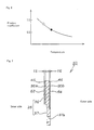
- Fig. 6 is a graph showing the variation of the friction coefficient associated with the friction member of a brake disk in a second embodiment according to the present invention with the temperature of the same.
- Fig. 7 is a sectional view of a brake disk in a third embodiment according to the present invention.
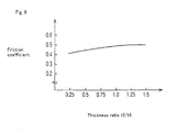
- Fig. 8 is a graph showing the relation between friction coefficient associated with the brake disk in the third embodiment and the thickness of friction members.
- Amotorcycle 10 has a body frame 11, a front fork 12 supported in a head pipe 11a included in the body frame 11, a handlebar 13 attached to the upper end of the front fork 12, a front wheel 14 attached to the lower end of the front fork 12, a fuel tank 15 mounted on a front part of the body frame 11, a seat 16 mounted on a part of the body frame behind the fuel tank 15, a power unit 17 (formed by combining an engine 17a and a transmission 17b) disposed under and attached to a front part of the body frame 11, swing arms 18 pivotally joined for swinging to a rear part of the body frame 11, and a rear wheel 19 supported on a rear end part of the swing arm 18 and provided with a brake disk 30 in a preferred embodiment according to the present invention.
- the brake disk 30 of the present invention will be described hereinafter.
- Fig. 2 is a sectional view taken on line 2-2 in Fig. 1.
- a wheel 20 comprises a hub 21, a spoke 22 and a rim 23.
- the wheel 20 is disposed between the swing arms 18 and is supported for rotation by a rear axle 24 attached to the swing arms 18.
- a tire 25 is fitted on the rim 23.
- a sprocket 26 is fastened to the right side surface of the hub 21 with bolts 27 and a drive chain, not shown, is wound round the sprocket 26.
- the brake disk 30 is fastened to the left side surface of the hub 21 with bolts 31 and a caliper 32 is combined with a lower part of the brake disk 30.
- the caliper 32 is attached to the body of the motorcycle 10 (Fig. 1). Brake pads 33 are held on the caliper 32 so as to face an inner friction member 40 and an outer friction member 42 of the brake disk 30, respectively. The calipers 33 held on the caliper 32 are pressed against the inner friction member 40 and the outer friction member 42, respectively, to exert a braking force to the brake disk 30.
- Fig. 3 is a sectional view of a brake disk in a first embodiment according to the present invention.
- the brake disk 30 has a disk body 35 formed of a titanium alloy, an inner friction member 40 formed of a stainless steel and bonded by brazing to the inner surface 36a, i.e., a surface facing the wheel 20, of the brake disk 35, and an outer friction member 42 formed of a stainless steel and bonded by brazing to the outer surface 36b, i.e., a surface not facing the wheel 20.
- the disk body 35 has an annular part 36 of a thickness tl and mounting lugs 37 of a thickness t2 provided with a through hole 37a and formed integrally with the annular part 36 so as to project radially inward from the inner circumference of the annular part 36.
- the disk body 35 is formed of a titanium alloy and is provided with a recess in the inner surface 36a facing the wheel 20. Although it is preferable that the titanium alloy contains 6% aluminum and 4% vanadium, the titanium alloy may be of any other composition.
- the inner friction member 40 is bonded to the inner surface 36a facing the wheel 20 of the annular part 36 with a brazing filler metal layer 45, and the outer friction member 42 is bonded to the outer surface 36b of the same with a brazing filler metal layer 46.
- the surface of the outer friction member 42 is flush with the outer surface of the disk body 35.
- the inner friction member 40 is formed of a stainless steel, such as SUS410M, JIS, in a shape substantially the same as that of the inner surface 36a of the annular part 36.
- the thickness t3 of the inner friction member 40 is in the range of 0.3 to 0.5 mm, but the thickness is not limited thereto.
- the outer friction member 42 is formed of a stainless steel, such as SUS410M, JIS, in a shape substantially the same as that of the outer surface 36b of the disk body 35.
- the thickness t4 of the outer friction member 42 similarly to that of the inner friction member 40, in the range of 0.3 to 0.5 mm, but the thickness is not limited thereto.
- the inner brazing filler metal sheet 45 and the outer brazing filler metal sheet 46 are formed of an activated silver solder containing 70% silver, 28%copper and 2% titanium.
- the inner brazing filler metal sheet 45 and the outer brazing filler metal sheet 46 may be formed of any suitable material other than the activated silver solder.
- Fig. 4 is a plan view of the brake disk 30 in the first embodiment as viewed from the side of the wheel 19 (Fig. 2).
- the annular inner friction member 40 is bonded to the inner surface 36a (Fig. 3) of the disk body 35 by brazing, and the annular outer friction member 42 is bonded to the outer surface 36b (Fig. 3) by brazing to form the brake disk 30.
- Bolts 31 are passed through the through holes 37a of the brake disk 30 and are screwed in threaded holes formed in the hub 21 to fasten the brake disk 30 to the hub 21.
- a brake disk in Comparative example 1 is formed of a stainless steel
- a brake disk in Comparative example 2 is formed of a titanium alloy
- a brake disk in Comparative example 3 is formed of an aluminum alloy
- the brake disk in the first embodiment is a brake disk in Example.
- the weight of each brake disk is represented by a multiple of the weight W of the brake disk in Comparative example 1.
- Friction coefficient associated with Comparative example 1 is 0.5 and Comparative example 1 has a weight of W. The friction coefficient is sufficiently large but the weight is large. Friction coefficient associated with Comparative example 2 varies in the range of 0.2 to 0.7 and Comparative example 2 has a weight of 0.6W. The weight is small enough, but the friction coefficient varies and it is difficult to produce stable braking force. Friction coefficient associated with Comparative example 3 is 0.3 and Comparative example 3 has a weight of 0.3W. The weight, similarly to that of the Comparative example 2, is small enough, but the friction coefficient is small and it is difficult to produce sufficient braking force. Friction coefficient associated with Example is 0.5 and Example has a weight of 0.7W. The friction coefficient is large enough and the weight is satisfactorily small.
- the brake disk in the first embodiment has the disk body 35 formed of the light titanium alloy having a high strength, and the friction members 40 and 42 respectively formed of the different iron-base materials are bonded to the opposite surfaces of the disk body 35 by brazing.
- the bonding of members of different materials by brazing enables the use of the light titanium alloy having a high strength for forming the disk body 35, which enables the brake disk 30 to be formed in a lightweight structure.
- FIGs. 5(a) to 5(c) illustrate a brazing method employed in fabricating the brake disk 30 in the first embodiment.
- a brazing jig 50 having a support plate 51 and a pressure plate 53 is prepared, the outer friction member 42 is located between a plurality of pins 54 attached to the support plate 51, and an outer brazing filler metal sheet 46, the disk body 35, an inner brazing filler metal sheet 45 and the inner friction member 40 are superposed in that order on the outer friction member 42.
- the pressure plate 53 is placed on the inner friction member 40.
- the thickness of workpieces for forming the inner friction member 40 and the outer friction member 42 is slightly greater than a desired thickness of the inner friction member 40 and the outer friction member 42 in the range of 0.3 to 0.5 mm to provide the workpieces with a grinding allowance.
- the inner brazing filler metal sheet 45 has a shape similar to that of the inner friction member 40 and a thickness of 100 ⁇ m, but the shape and the thickness of the inner brazing filler metal sheet 45 are not limited thereto.
- the outer brazing filler metal sheet 46 has a shape similar to that of the outer friction member 42 and a thickness of 100 ⁇ m, but the shape and the thickness of the inner brazing filler metal sheet 46 are not limited thereto.
- the inner brazing filler metal sheet 45 and the outer brazing filler metal sheet 46 may be substituted by powder.
- a load P of about 2 kg is applied in the direction of the blank arrow to the pressure plate 53 to apply a pressure of 0.01 kgf/cm 2 to surfaces to be bonded together by brazing.
- the vacuum vessel 55 is evacuated to a vacuum of 1.5 torr, and then the interior atmosphere of the vacuum vessel 55 is heated at 850 °C for 40 min to melt the inner brazing filler metal sheet 45 and the outer brazing filler metal sheet 46. Consequently, the inner friction member 40 is bonded to the inner surface 36a of the disk body 35 by the molten inner brazing filler metal sheet 45 and the outer friction member 42 is bonded to the outer surface 36b (Fig. 3) of the disk body 35 by the molten outer brazing filler metal sheet 46.
- the brazing method loads the pressure plate 53 with the load P of about 2 kg to prevent the deformation of the inner friction member 40 and the outer friction member 42.
- the outer friction member 42, the outer brazing filler metal sheet 46, the disk body 35, the inner brazing filler metal sheet 45 and the inner friction member 40 are located by the pins 54 to prevent the dislocation of those members during brazing.
- the brazing method is able to bond together members of different materials, such as a member of a titanium alloy and a member of an iron-base material.
- the disk body 35 can be formed by a light titanium alloy having a high strength, which is effective in reducing the weight of the brake disk 30.
- the surfaces of the inner friction member 40 and the outer friction member 42 bonded to the disk body 35 are machined with a cutting tool 57 to finish the surfaces of the inner friction member 40 and the outer friction member 42 in a flatness required of the brake disk 30 .
- the thickness of the thus finished friction members 40 and 42 is in the range of 0.3 to 0.5 mm. If the surfaces of the inner friction member 40 and the outer friction member 42 as bonded to the disk body 35 have a flatness required of the brake disk 30, the same surfaces do not need to be finished by machining.
- the friction members 40 and 42 are bonded to the disk body 35 by the brazing method.
- the friction members 40 and 42 can be easily bonded to the disk body 35 simply by spreading a brazing filler metal between the friction members 40 and 42, and the disk body 35 and melting the brazing filler metal.
- a brake disk in a second embodiment according to the present invention will be described hereinafter.
- the brake disk in the second embodiment has a disk body formed of an aluminum alloy, and friction members formed of a stainless steel and bonded to the disk body by brazing.
- the brake disk in the second embodiment is the same as the brake disk 30 in the first embodiment except that the former has the disk body formed of the aluminum alloy.
- Fig. 6 is a graph showing the variation of the friction coefficient associated with the friction member of the brake disk in the second embodiment with the temperature of the same, in which friction coefficient associated with the friction member is measured on the vertical axis, the temperature of the friction member is measured on the horizontal axis, a solid circle is for a brake disk in Comparative example and a blank circle is for the brake disk in Example.
- the brake disk in Comparative example has a disk body integrally provided with friction parts and formed of a stainless steel.
- the brake disk in Example is the brake disk in the second embodiment.
- the stainless steel has a heat transfer coefficient of about 0.18 cal/cm ⁇ s ⁇ °Cand the aluminum alloy has a heat transfer coefficient of bout 0.53 cal/cm ⁇ s ⁇ °C.
- the heat transfer coefficient of the aluminum alloy is as great as about three times that of the stainless steel.
- the temperature of the friction member and the friction coefficient associated with the friction member were measured by rotating the brake disk at a predetermined rotating speed, and pressing brake pads against the rotating brake disk for braking.
- the disk body of the brake disk in the second embodiment is formed of the aluminum alloy, heat generated in the friction member during braking can be satisfactorily absorbed by the disk body. Therefore, even if large braking energy is produced, the rise of the temperature of the friction member can be suppressed as indicated by a blank circle. Consequently, the friction coefficient remains substantially constant and a sufficient braking force can be produced.
- the brake disk in the second embodiment similarly to that in the first embodiment, can be formed in a lightweight structure, which is effective in improving the performance of the motorcycle.
- a brake disk in a third embodiment according to the present invention will be described with reference to Fig. 7 showing the brake disk in a sectional view of, in which parts like or corresponding to those of the brake disk in the first embodiment are denoted by the same reference characters and the description thereof will be omitted.
- a brake disk 60 has a disk body 35 formed of a titanium alloy, an inner friction member 62 and an outer friction member 64. The inner friction member 62 and the outer friction member 64 are bonded to the inner surface 36a of the disk body 35 on the side of a wheel and an outer surface 36b of the disk body 35 opposite the inner surface 36a, respectively, by brazing.
- the inner friction member 62 is bonded to the inner surface 36a of an annular part 36 by an inner brazing filler meal layer 45 and the outer friction member 64 is bonded to the outer surface 36b of the annular part 36 by an outer brazing filler meal layer 46.
- the surface of the outer friction member 64 is flush with the surface of the outer surface of the disk body 35.
- the inner friction member 62 is formed of a stainless steel, such as SUS410M, JIS, in a shape substantially the same as that of the inner surface 36a of the annular part 36.
- the thickness t5 of the inner friction member 62 is in the range of 0.3 to 0.5 mm, but the thickness is not limited thereto.
- the outer friction member 64 is formed of a stainless steel, such as SUS410M, JIS, in a shape substantially the same as that of the outer surface 36b of the disk body 35.
- the thickness t6 of the outer friction member 64 is, similarly to that of the inner friction member 62, in the range of 0.3 to 0.5 mm, but the same thickness is not limited thereto.
- the thickness t5 of the inner friction member 62 of the brake disk 60 is greater than the thickness t6 of the outer friction member 64 of the brake disk 60, i.e., the inner friction member 62 and the outer friction member 64 have different thicknesses, respectively.
- the brake disk 60 is attached to the hub 21 of the wheel 19 of the motorcycle 10 shown in Fig. 1 with the thicker friction member 62 facing the wheel 19 and the thinner friction member 64 faced outward so as to be exposed to running wind more efficiently than the former.
- the inner friction member 62 and the outer friction member 64 are the same in construction as the inner friction member 40 and the outer friction member 42 of the first embodiment, respectively, except that the inner friction member 62 and the outer friction member 64 have the different thicknesses t5 and t6, respectively.
- the outer surface of the brake disk 60 i.e., the outer friction member 64
- the inner friction member 62 is heated at a temperature higher than that at which the outer friction member 64 is heated. Friction coefficients associated with the inner friction member 62 and the outer friction member 64 decrease as the temperatures of the inner friction member 62 and the outer friction member 64 rise. Therefore, it is important to maintain the friction members at a fixed temperature.
- the inner friction member 62 is formed in the thickness t5 greater than the thickness t6 of the outer friction member 64.
- the thicker inner friction member 62 is capable of absorbing a large amount of heat generated when a braking force is applied to the brake disk 60.
- the inner friction member 62 and the outer friction member 64 can be maintained at substantially the same temperature even though the inner friction member 62 is exposed to running wind less efficiently than the outer friction member 64. Consequently, both the friction coefficient associated with the inner friction member 62 and the friction coefficient associated with the outer friction member 64 can be held on a substantially fixed level and substantially the same braking force can be produced on the opposite sides of the brake disk 60.
- Fig. 8 is a graph showing the relation between friction coefficient associated with the brake disk in the third embodiment and the thickness of the friction members, in which the mean of the friction coefficients respectively associated with the friction members 62 and 64 is measured on the vertical axis and the thickness ratio t5/t6, i.e., the ratio of the thickness t5 of the inner friction member 62 to the thickness t6 of the outer friction member 64, is measured on the horizontal axis.
- Friction coefficients were measured under measuring conditions that are more severe than those for the measurement of the friction coefficients shown in Table 1 associated with the brake disks in the first embodiment and those in the comparative examples to elucidate the effect of the difference in thickness between the inner and the outer friction member on the difference in friction coefficient. Therefore, the values of the friction coefficients are different from those shown in Table 1.
- Friction coefficients respectively associated with the opposite surfaces of the brake disk are 0.41 when the thickness ratio t5/t6 is 0.25, i.e., when the thickness t5 of the inner friction member 62 is 1/4 of the thickness t6 of the outer friction member 64. Friction coefficients respectively associated with the opposite surfaces of the brake disk are 0.43 when the thickness ratio t5/t6 is 0.5, i.e., when the thickness t5 of the inner friction member 62 is 1/2 of the thickness t6 of the outer friction member 64.
- Friction coefficients respectively associated with the opposite surfaces of the brake disk are 0.46 when the thickness ratio t5/t6 is 0.75, i.e., when the thickness t5 of the inner friction member 62 is 3/4 of the thickness t6 of the outer friction member 64.
- Friction coefficients respectively associated with the opposite surfaces of the brake disk are 0.48 when the thickness ratio t5/t6 is 1.0, i.e., when the thickness t5 of the inner friction member 62 is equal to the thickness t6 of the outer friction member 64. Friction coefficients respectively associated with the opposite surfaces of the brake disk are 0.49 when the thickness ratio t5/t6 is 1.25, i.e., when the thickness t5 of the inner friction member 62 is 1.25 times the thickness t6 of the outer friction member 64.
- Friction coefficients respectively associated with the opposite surfaces of the brake disk are 0.5 when the thickness ratio t5/t6 is 1.5, i.e., when the thickness t5 of the inner friction member 62 is 1.5 times the thickness t6 of the outer friction member 64.
- friction coefficients respectively associated with the opposite surfaces of the brake disk are 0.46, which are fairly satisfactory, when the thickness t5 of the inner friction member 62 is equal to the thickness t6 of the outer friction member 64.
- Friction coefficients respectively associated with the opposite surfaces of the brake disk can be increased beyond 0.46 when the thickness t5 of the inner friction member 62 is greater than the thickness t6 of the outer friction member 64. Particularly, when the thickness t5 of the inner friction member 62 is 1.t times the thickness 5t of the outer friction member 64, friction coefficients associated with the opposite surfaces of the brake disk is as large as 0.5.
- the respective disk bodies of the brake disks in the first and the third embodiment are formed of the titanium alloy; those disk bodies may be formed of a light material having a high rigidity other than the titanium alloy, such as titanium, aluminum, an aluminum alloy or the like.
- the disk body of the brake disk in the second embodiment is formed of an aluminum alloy; this disk body may be formed of a material having a large heat transfer coefficient, such as aluminum.
- the friction members of the foregoing embodiments are formed of the stainless steel, the same may be formed of an iron-base material other than the stainless steel, such as a carbon steel or cast iron, provided that the iron-base material is capable of forming friction members having a frictional property represented by a satisfactory friction coefficient.
- the inner friction member 62 facing the wheel is thick and the outer friction member 64 not facing the wheel is thin.
- the inner friction member 62 may be thin and the outer friction member 64 may be thick.
- the disk body is formed of the titanium alloy or the aluminum alloy, and the friction members formed of the iron-base material are bonded to the opposite surfaces of the disk body by brazing.
- the disk body formed of the light titanium alloy or aluminum alloy reduces the weight of the brake disk.
- the friction members are bonded to the disk body by the brazing method.
- the disk body is formed of the titanium alloy or the aluminum alloy, the friction members are formed of the iron-base material, and the brazing filler metal is sandwiched between the disk body and the friction members, which are formed of different materials, respectively, and the friction members can be bonded to the disk body simply by melting the brazing filler metal, which reduces the cost of the brake disk.
- the disk body is formed of the titanium alloy or the aluminum alloy, and the friction members formed of the iron-base material are bonded to the opposite surfaces of the disk body by brazing.
- the titanium alloy or the aluminum alloy is a light material having a high strength and reduces the weight of the brake disk.
- the pair of friction members are formed in different thicknesses, respectively, the thicker friction member is bonded to the inner surface of the disk body facing the wheel and the thinner friction member is bonded to the outer surface of the disk body.
- the thicker friction member bonded to the inner surface of the disk body on the side of the wheel is capable of absorbing a large amount of heat generated when a braking force is applied to the brake disk.
- the inner friction member facing the wheel and the outer friction member not facing the wheel can be maintained at substantially the same temperature. Consequently, is capable of absorbing a large amount of heat generated when a braking force is applied to the brake disk.
- the inner friction member facing the wheel and the outer friction member not facing the wheel are maintained at the same temperature. Consequently, both the friction coefficient associated with the inner friction member and the friction coefficient associated with the outer friction member can be held on a substantially fixed level.
- a brake disk 30 has a disk body 35 formed of a titanium alloy, and inner and outer friction members 40, 42 formed of a stainless steel and bonded to the opposite surfaces 36a, 36b of the disk body 35 by a brazing method.
- the friction members 40, 42 can be simply bonded to the opposite surfaces 36a, 36b of the disk body 35 .
Landscapes
- Engineering & Computer Science (AREA)
- General Engineering & Computer Science (AREA)
- Mechanical Engineering (AREA)
- Braking Arrangements (AREA)
- Pressure Welding/Diffusion-Bonding (AREA)
Abstract
Description
The present invention forms friction parts by attaching a frictional material to a brake disk by spraying or application. The thickness of the friction parts is in the range of about 10 to about 20 µm.
Some type of brake disks need friction parts of a greater thickness.
An explosive cladding method has troublesome steps of putting an alloy steel member on an aluminum member, mounting a buffer on the alloy steel member, putting a proper amount of explosive on the buffer, and detonating the explosive by a detonator attached to one end of the explosive. Thus, the explosive cladding method is costly.
A process for uniting together the pair of metal plates and the plate-shaped member needs a step of forming a plurality of through holes in the pair of metal plates and the plate-shaped member and a step of pressing down the ends of a plurality of rivets. Thus, this technique needs many parts, which increases the cost.
An explosive cladding method proposed in JP-A No. H9-42339 and a rivet bonding method disclosed in Japanese Utility Model No. 2557898 increase the manufacturing cost of the brake disk. Manufacturing techniques that replace the know techniques have been desired.
The friction members are bonded to the disk body by brazing. The friction members can be bonded to the disk body simply by forming a brazing filler metal layer between each of the friction members and the disk body and melting the brazing filler metal layer.
The titanium alloy or the aluminum alloy is light and has a high strength and enables the reduction of the weight of the brake disk without deteriorating the braking ability of the brake disk.
The friction members are bonded to the disk body by a brazing method. The friction members can be bonded to the disk body simply by forming a brazing filler metal layer between each of the friction members and the disk body and melting the brazing filler metal layer.
Amotorcycle 10 has a
The
The
The
The
Preferably, the inner brazing
The annular
| Material | Friction coefficient (µ) | Weight | |
| Comparative example 1 | Stainless steel | 0.5 | w |
| Comparative example 2 | Titanium alloy | 0.2-0.7 | 0.6w |
| Comparative example 3 | Aluminum alloy | 0.3 | 0.3w |
| Example | Titanium alloy and stainless steel | 0.5 | 0.7w |
The weight of each brake disk is represented by a multiple of the weight W of the brake disk in Comparative example 1.
Friction coefficient associated with Comparative example 2 varies in the range of 0.2 to 0.7 and Comparative example 2 has a weight of 0.6W. The weight is small enough, but the friction coefficient varies and it is difficult to produce stable braking force.
Friction coefficient associated with Comparative example 3 is 0.3 and Comparative example 3 has a weight of 0.3W. The weight, similarly to that of the Comparative example 2, is small enough, but the friction coefficient is small and it is difficult to produce sufficient braking force.
Friction coefficient associated with Example is 0.5 and Example has a weight of 0.7W. The friction coefficient is large enough and the weight is satisfactorily small.
Figs. 5(a) to 5(c) illustrate a brazing method employed in fabricating the
In a step shown in Fig. 5(a), a
Preferably, the inner brazing
Preferably, the outer brazing
The inner brazing
The
If the surfaces of the
The brake disk in the second embodiment has a disk body formed of an aluminum alloy, and friction members formed of a stainless steel and bonded to the disk body by brazing. Thus, the brake disk in the second embodiment is the same as the
The stainless steel has a heat transfer coefficient of about 0.18 cal/cm · s · °Cand the aluminum alloy has a heat transfer coefficient of bout 0.53 cal/cm · s · °C. Thus, the heat transfer coefficient of the aluminum alloy is as great as about three times that of the stainless steel.
The temperature of the friction member and the friction coefficient associated with the friction member were measured by rotating the brake disk at a predetermined rotating speed, and pressing brake pads against the rotating brake disk for braking.
Moreover, the brake disk in the second embodiment, similarly to that in the first embodiment, can be formed in a lightweight structure, which is effective in improving the performance of the motorcycle.
A
The
The
Therefore, when a braking force is exerted on the
Fig. 8 is a graph showing the relation between friction coefficient associated with the brake disk in the third embodiment and the thickness of the friction members, in which the mean of the friction coefficients respectively associated with the
Particularly, when the thickness t5 of the
The disk body of the brake disk in the second embodiment is formed of an aluminum alloy; this disk body may be formed of a material having a large heat transfer coefficient, such as aluminum.
Although the friction members of the foregoing embodiments are formed of the stainless steel, the same may be formed of an iron-base material other than the stainless steel, such as a carbon steel or cast iron, provided that the iron-base material is capable of forming friction members having a frictional property represented by a satisfactory friction coefficient.
In the brake disk stated in the first aspect, the disk body is formed of the titanium alloy or the aluminum alloy, and the friction members formed of the iron-base material are bonded to the opposite surfaces of the disk body by brazing. The disk body formed of the light titanium alloy or aluminum alloy reduces the weight of the brake disk.
The friction members are bonded to the disk body by the brazing method. The disk body is formed of the titanium alloy or the aluminum alloy, the friction members are formed of the iron-base material, and the brazing filler metal is sandwiched between the disk body and the friction members, which are formed of different materials, respectively, and the friction members can be bonded to the disk body simply by melting the brazing filler metal, which reduces the cost of the brake disk.
To achieve this, a
Claims (2)
- A brake disk comprising: a disk body (35) formed of a titanium alloy or an aluminum alloy; and friction members (40,42;62,64) formed of an iron-base material and bonded to opposite surfaces (36a,36b) of the disk body (35) by brazing.
- A brake disk for a motorcycle (10), to be mounted on a hub (21) included in a wheel (20), said brake disk (30;60) comprising: a disk body (35) formed of a titanium alloy or an aluminum alloy; and friction members (40,42;62,64) formed of an iron-base material and bonded to the opposite surfaces (36a, 36b) of the disk body (35) by brazing; wherein the pair of friction members (40,42;62,64) have different thicknesses, respectively.
Applications Claiming Priority (2)
| Application Number | Priority Date | Filing Date | Title |
|---|---|---|---|
| JP2000096460A JP4627346B2 (en) | 2000-03-31 | 2000-03-31 | brake disc |
| JP2000096460 | 2000-03-31 |
Publications (3)
| Publication Number | Publication Date |
|---|---|
| EP1138970A2 true EP1138970A2 (en) | 2001-10-04 |
| EP1138970A3 EP1138970A3 (en) | 2002-03-20 |
| EP1138970B1 EP1138970B1 (en) | 2006-06-07 |
Family
ID=18611227
Family Applications (1)
| Application Number | Title | Priority Date | Filing Date |
|---|---|---|---|
| EP01104154A Expired - Lifetime EP1138970B1 (en) | 2000-03-31 | 2001-02-21 | Brake disk composed from different metals and method for manufacturing the same |
Country Status (5)
| Country | Link |
|---|---|
| US (1) | US6491142B2 (en) |
| EP (1) | EP1138970B1 (en) |
| JP (1) | JP4627346B2 (en) |
| DE (2) | DE60120262T8 (en) |
| ES (1) | ES2266033T3 (en) |
Cited By (2)
| Publication number | Priority date | Publication date | Assignee | Title |
|---|---|---|---|---|
| EP1496282A1 (en) * | 2003-07-11 | 2005-01-12 | Shimano Inc. | Bicycle disk brake apparatus with laminated components |
| EP1627809A3 (en) * | 2004-08-19 | 2007-10-24 | Shimano Inc. | Bicycle disk brake rotor with laminated components having differing thicknesses |
Families Citing this family (19)
| Publication number | Priority date | Publication date | Assignee | Title |
|---|---|---|---|---|
| US20030188931A1 (en) * | 2001-03-02 | 2003-10-09 | Labrash Richard | Brake mechanism for resilient wheel |
| US7066235B2 (en) * | 2002-05-07 | 2006-06-27 | Nanometal, Llc | Method for manufacturing clad components |
| US20040094360A1 (en) * | 2002-11-06 | 2004-05-20 | Calsonic Kansei Corporation | Acoustic dumper for exhaust system |
| US20040178029A1 (en) * | 2003-03-13 | 2004-09-16 | J. L. French Automotive Castings, Inc. | Lightweight brake rotor with cooling passageways |
| DE10338632B4 (en) * | 2003-08-22 | 2005-11-03 | Wilhelm Kächele GmbH | Eccentric screw pump with erosion-resistant rotor |
| FR2860740B1 (en) * | 2003-10-10 | 2007-03-02 | Snecma Moteurs | METHOD FOR BRAZING A TURBOMACHINE COMPRESSOR RECTIFIER |
| US20050087406A1 (en) * | 2003-10-22 | 2005-04-28 | Meckel Nathan K. | Brake disks and methods for coating |
| JP2006029552A (en) * | 2004-07-21 | 2006-02-02 | Shimano Inc | Bicycle disc rotor |
| DE102005031291A1 (en) * | 2005-07-05 | 2007-01-11 | Daimlerchrysler Ag | Inexpensive, corrosion-resistant composite brake disk, for use in automobile disk brakes, comprises cast iron carrier disk bonded to friction ring of corrosion-resistant material, e.g. highly alloyed steel |
| TW200809113A (en) * | 2006-08-11 | 2008-02-16 | Metal Ind Res & Dev Ct | Structure of braking disc having a composition |
| US20080131621A1 (en) * | 2006-12-05 | 2008-06-05 | Warran Boyd Lineton | Method for fusing hard ceramic-metallic layer on a brake rotor |
| US8960382B2 (en) * | 2008-04-18 | 2015-02-24 | GM Global Technology Operations LLC | Chamber with filler material to dampen vibrating components |
| US8522931B2 (en) | 2010-03-30 | 2013-09-03 | Shimano Inc. | Disk brake rotor |
| RU2454577C1 (en) * | 2010-12-30 | 2012-06-27 | Александр Юрьевич Романов | Motorcycle brake disc rotor |
| JP5967514B2 (en) * | 2011-09-01 | 2016-08-10 | 佐藤 良明 | Disc brake rotor |
| DE202011052265U1 (en) * | 2011-12-12 | 2013-03-13 | Faiveley Transport Witten Gmbh | Built shaft brake disk |
| US9776241B2 (en) | 2012-04-18 | 2017-10-03 | Xiaodi Huang | High thermal conductivity disk brakes |
| DE102021128374B4 (en) | 2021-10-29 | 2023-10-26 | IMPACT-Innovations-GmbH | Method for producing a brake disc and brake disc |
| JP2024112048A (en) * | 2023-02-07 | 2024-08-20 | ヤマハ発動機株式会社 | Disc brake device and saddle-type vehicle |
Family Cites Families (23)
| Publication number | Priority date | Publication date | Assignee | Title |
|---|---|---|---|---|
| CH528684A (en) * | 1970-02-12 | 1972-09-30 | Messier Sa | Disc brake |
| DE2108950A1 (en) * | 1971-02-25 | 1972-08-31 | Dr.Ing.H.C. F. Porsche Kg, 7000 Stuttgart | Multi-part brake disc for disc brakes in vehicles |
| JPS5410866A (en) * | 1977-06-24 | 1979-01-26 | Aisin Seiki Co Ltd | Disc brake |
| JPS54118990U (en) * | 1978-02-09 | 1979-08-20 | ||
| JPS556069A (en) * | 1978-06-30 | 1980-01-17 | Yamaha Motor Co Ltd | Brake disk and its manufacturing method |
| JPS5790427A (en) * | 1980-11-28 | 1982-06-05 | Yamaha Motor Co Ltd | Brake disk of motorcycle |
| JPS57137730A (en) * | 1981-02-17 | 1982-08-25 | Takaoka Kogyo Kk | Manufacture of disc brake rotor |
| JPS5891936A (en) * | 1981-11-26 | 1983-06-01 | Yamaha Motor Co Ltd | Manufacture of brake disc |
| JPS58152945A (en) * | 1982-03-08 | 1983-09-10 | Sumitomo Electric Ind Ltd | Disc for disc brake |
| JPS5962738A (en) * | 1982-09-30 | 1984-04-10 | Yamaha Motor Co Ltd | Brake disc |
| JPS59194139A (en) * | 1983-04-15 | 1984-11-02 | Nissan Motor Co Ltd | Ventilated brake disk |
| GB8428953D0 (en) * | 1984-11-16 | 1984-12-27 | Dunlop Ltd | Bonding of carbon-based components |
| JPS63140130A (en) * | 1986-11-29 | 1988-06-11 | Daido Kogyo Co Ltd | Brake disk |
| JPH01153826A (en) * | 1987-12-11 | 1989-06-16 | Toyota Motor Corp | Disk brake rotor |
| JP2679162B2 (en) * | 1988-10-22 | 1997-11-19 | スズキ株式会社 | Disc brake rotor structure |
| JPH04224884A (en) * | 1990-12-27 | 1992-08-14 | Mitsubishi Materials Corp | Composite rotor disc |
| US5620042A (en) * | 1993-06-30 | 1997-04-15 | Kelsey-Hayes Company | Method of casting a composite disc brake rotor |
| JPH08226478A (en) | 1995-02-17 | 1996-09-03 | Honda Motor Co Ltd | Disc brake |
| JPH0942339A (en) | 1995-08-04 | 1997-02-10 | Asahi Chem Ind Co Ltd | Brake disc consisting of composite metal layers |
| US5626211A (en) * | 1995-10-03 | 1997-05-06 | Gewelber; Ytzhak | Multi-layer disk brake rotor |
| US6086688A (en) * | 1997-07-28 | 2000-07-11 | Alcan International Ltd. | Cast metal-matrix composite material and its use |
| US6088906A (en) * | 1997-09-16 | 2000-07-18 | Ut-Battelle, Llc | Method of manufacturing squirrel cage rotors |
| US6032769A (en) * | 1998-09-11 | 2000-03-07 | Hayes Lemmerz International, Inc. | Modular rotor |
-
2000
- 2000-03-31 JP JP2000096460A patent/JP4627346B2/en not_active Expired - Fee Related
-
2001
- 2001-02-21 ES ES01104154T patent/ES2266033T3/en not_active Expired - Lifetime
- 2001-02-21 DE DE60120262T patent/DE60120262T8/en active Active
- 2001-02-21 EP EP01104154A patent/EP1138970B1/en not_active Expired - Lifetime
- 2001-02-21 DE DE60120262A patent/DE60120262D1/en not_active Expired - Lifetime
- 2001-03-30 US US09/820,917 patent/US6491142B2/en not_active Expired - Fee Related
Cited By (3)
| Publication number | Priority date | Publication date | Assignee | Title |
|---|---|---|---|---|
| EP1496282A1 (en) * | 2003-07-11 | 2005-01-12 | Shimano Inc. | Bicycle disk brake apparatus with laminated components |
| US8365881B2 (en) | 2003-07-11 | 2013-02-05 | Shimano, Inc. | Bicycle disk brake apparatus with laminated components |
| EP1627809A3 (en) * | 2004-08-19 | 2007-10-24 | Shimano Inc. | Bicycle disk brake rotor with laminated components having differing thicknesses |
Also Published As
| Publication number | Publication date |
|---|---|
| DE60120262T2 (en) | 2006-09-21 |
| EP1138970A3 (en) | 2002-03-20 |
| DE60120262T8 (en) | 2007-07-19 |
| EP1138970B1 (en) | 2006-06-07 |
| JP4627346B2 (en) | 2011-02-09 |
| DE60120262D1 (en) | 2006-07-20 |
| US20010045332A1 (en) | 2001-11-29 |
| JP2001280381A (en) | 2001-10-10 |
| ES2266033T3 (en) | 2007-03-01 |
| US6491142B2 (en) | 2002-12-10 |
Similar Documents
| Publication | Publication Date | Title |
|---|---|---|
| EP1138970A2 (en) | Brake disk composed from different metals and method for manufacturing the same | |
| US7416060B2 (en) | Bicycle disc brake rotor | |
| US5862892A (en) | Composite rotor for caliper disc brakes | |
| US8550220B2 (en) | Bicycle brake pad | |
| US4049090A (en) | Brake discs | |
| US8052224B2 (en) | Lightweight aluminum wheel with magnesium rim | |
| US5878843A (en) | Laminated brake rotor | |
| US8881873B2 (en) | Bicycle disc brake rotor | |
| US11242902B2 (en) | Brake disc and method for producing a brake disc | |
| US20060037819A1 (en) | Bicycle disk brake rotor with laminated components having differing thicknesses | |
| US20050269167A1 (en) | Bicycle disk brake pad with welded and adhesively bonded layers | |
| US3790219A (en) | Wheel | |
| US4488761A (en) | Wheel disc brake | |
| JPS5813237A (en) | Manufacture of ventilated disc plate | |
| JPS6358296B2 (en) | ||
| JP2009504995A (en) | Disc brake with brake disc ring formed from a brittle material and vehicle fitted with one or more disc brakes of this kind | |
| KR20140067347A (en) | Reduced-weight brake parts | |
| US20240309922A1 (en) | Brake disc for a disc brake | |
| JP4996761B2 (en) | Disc rotor for disc brake | |
| JPH0526268A (en) | Brake disc and manufacture thereof | |
| US7677366B2 (en) | Disc brake caliper and manufacturing method of disc brake caliper | |
| EP1864029B1 (en) | Disc brake caliper and manufacturing method of disc brake caliper | |
| JP2000170804A (en) | Disc brake device | |
| TWI398373B (en) | Wear discs | |
| JPH0942339A (en) | Brake disc consisting of composite metal layers |
Legal Events
| Date | Code | Title | Description |
|---|---|---|---|
| PUAI | Public reference made under article 153(3) epc to a published international application that has entered the european phase |
Free format text: ORIGINAL CODE: 0009012 |
|
| AK | Designated contracting states |
Kind code of ref document: A2 Designated state(s): DE ES IT Kind code of ref document: A2 Designated state(s): AT BE CH CY DE DK ES FI FR GB GR IE IT LI LU MC NL PT SE TR |
|
| AX | Request for extension of the european patent |
Free format text: AL;LT;LV;MK;RO;SI |
|
| PUAL | Search report despatched |
Free format text: ORIGINAL CODE: 0009013 |
|
| AK | Designated contracting states |
Kind code of ref document: A3 Designated state(s): AT BE CH CY DE DK ES FI FR GB GR IE IT LI LU MC NL PT SE TR |
|
| AX | Request for extension of the european patent |
Free format text: AL;LT;LV;MK;RO;SI |
|
| 17P | Request for examination filed |
Effective date: 20020620 |
|
| AKX | Designation fees paid |
Free format text: DE ES IT |
|
| GRAP | Despatch of communication of intention to grant a patent |
Free format text: ORIGINAL CODE: EPIDOSNIGR1 |
|
| RAP1 | Party data changed (applicant data changed or rights of an application transferred) |
Owner name: HONDA GIKEN KOGYO KABUSHIKI KAISHA |
|
| GRAS | Grant fee paid |
Free format text: ORIGINAL CODE: EPIDOSNIGR3 |
|
| GRAA | (expected) grant |
Free format text: ORIGINAL CODE: 0009210 |
|
| AK | Designated contracting states |
Kind code of ref document: B1 Designated state(s): DE ES IT |
|
| PG25 | Lapsed in a contracting state [announced via postgrant information from national office to epo] |
Ref country code: IT Free format text: LAPSE BECAUSE OF FAILURE TO SUBMIT A TRANSLATION OF THE DESCRIPTION OR TO PAY THE FEE WITHIN THE PRESCRIBED TIME-LIMIT;WARNING: LAPSES OF ITALIAN PATENTS WITH EFFECTIVE DATE BEFORE 2007 MAY HAVE OCCURRED AT ANY TIME BEFORE 2007. THE CORRECT EFFECTIVE DATE MAY BE DIFFERENT FROM THE ONE RECORDED. Effective date: 20060607 |
|
| REF | Corresponds to: |
Ref document number: 60120262 Country of ref document: DE Date of ref document: 20060720 Kind code of ref document: P |
|
| REG | Reference to a national code |
Ref country code: ES Ref legal event code: FG2A Ref document number: 2266033 Country of ref document: ES Kind code of ref document: T3 |
|
| PLBE | No opposition filed within time limit |
Free format text: ORIGINAL CODE: 0009261 |
|
| STAA | Information on the status of an ep patent application or granted ep patent |
Free format text: STATUS: NO OPPOSITION FILED WITHIN TIME LIMIT |
|
| 26N | No opposition filed |
Effective date: 20070308 |
|
| PGFP | Annual fee paid to national office [announced via postgrant information from national office to epo] |
Ref country code: IT Payment date: 20110216 Year of fee payment: 11 Ref country code: DE Payment date: 20110216 Year of fee payment: 11 |
|
| PGFP | Annual fee paid to national office [announced via postgrant information from national office to epo] |
Ref country code: ES Payment date: 20110315 Year of fee payment: 11 |
|
| PG25 | Lapsed in a contracting state [announced via postgrant information from national office to epo] |
Ref country code: IT Free format text: LAPSE BECAUSE OF NON-PAYMENT OF DUE FEES Effective date: 20120221 |
|
| REG | Reference to a national code |
Ref country code: DE Ref legal event code: R119 Ref document number: 60120262 Country of ref document: DE Effective date: 20120901 |
|
| PG25 | Lapsed in a contracting state [announced via postgrant information from national office to epo] |
Ref country code: DE Free format text: LAPSE BECAUSE OF NON-PAYMENT OF DUE FEES Effective date: 20120901 |
|
| REG | Reference to a national code |
Ref country code: ES Ref legal event code: FD2A Effective date: 20130826 |
|
| PG25 | Lapsed in a contracting state [announced via postgrant information from national office to epo] |
Ref country code: ES Free format text: LAPSE BECAUSE OF NON-PAYMENT OF DUE FEES Effective date: 20120222 |