EP1138873A1 - System and method for communicating hydraulic control to a wireline retrievable downhole device - Google Patents
System and method for communicating hydraulic control to a wireline retrievable downhole device Download PDFInfo
- Publication number
- EP1138873A1 EP1138873A1 EP01303045A EP01303045A EP1138873A1 EP 1138873 A1 EP1138873 A1 EP 1138873A1 EP 01303045 A EP01303045 A EP 01303045A EP 01303045 A EP01303045 A EP 01303045A EP 1138873 A1 EP1138873 A1 EP 1138873A1
- Authority
- EP
- European Patent Office
- Prior art keywords
- safety valve
- tubing
- downhole device
- tubing retrievable
- retrievable
- Prior art date
- Legal status (The legal status is an assumption and is not a legal conclusion. Google has not performed a legal analysis and makes no representation as to the accuracy of the status listed.)
- Granted
Links
Images


Classifications
-
- E—FIXED CONSTRUCTIONS
- E21—EARTH DRILLING; MINING
- E21B—EARTH DRILLING, e.g. DEEP DRILLING; OBTAINING OIL, GAS, WATER, SOLUBLE OR MELTABLE MATERIALS OR A SLURRY OF MINERALS FROM WELLS
- E21B34/00—Valve arrangements for boreholes or wells
- E21B34/06—Valve arrangements for boreholes or wells in wells
- E21B34/10—Valve arrangements for boreholes or wells in wells operated by control fluid supplied from outside the borehole
- E21B34/105—Valve arrangements for boreholes or wells in wells operated by control fluid supplied from outside the borehole retrievable, e.g. wire line retrievable, i.e. with an element which can be landed into a landing-nipple provided with a passage for control fluid
- E21B34/106—Valve arrangements for boreholes or wells in wells operated by control fluid supplied from outside the borehole retrievable, e.g. wire line retrievable, i.e. with an element which can be landed into a landing-nipple provided with a passage for control fluid the retrievable element being a secondary control fluid actuated valve landed into the bore of a first inoperative control fluid actuated valve
-
- E—FIXED CONSTRUCTIONS
- E21—EARTH DRILLING; MINING
- E21B—EARTH DRILLING, e.g. DEEP DRILLING; OBTAINING OIL, GAS, WATER, SOLUBLE OR MELTABLE MATERIALS OR A SLURRY OF MINERALS FROM WELLS
- E21B29/00—Cutting or destroying pipes, packers, plugs, or wire lines, located in boreholes or wells, e.g. cutting of damaged pipes, of windows; Deforming of pipes in boreholes or wells; Reconditioning of well casings while in the ground
- E21B29/08—Cutting or deforming pipes to control fluid flow
Definitions
- This invention relates in general, to the operation of hydraulically controllable downhole devices and in particular to a system and method for communicating hydraulic control from a tubing retrievable downhole device to a wireline retrievable downhole device.
- One or more subsurface safety valves are commonly installed as part of the tubing string within oil and gas wells to protect against the communication of high pressure and high temperature formation fluids to the surface. These subsurface safety valves are designed to shut in production from the formation in response to a variety of abnormal and potentially dangerous conditions.
- TRSVs tubing retrievable safety valves
- TRSVs are normally operated by hydraulic fluid pressure.
- the hydraulic fluid pressure is typically controlled at the surface and transmitted to the TRSV via a hydraulic fluid line. Hydraulic fluid pressure must be applied to the TRSV to place the TRSV in the open position. When hydraulic fluid pressure is lost, the TRSV will operate to the closed position to prevent formation fluids from traveling therethrough. As such, TRSVs are fail safe valves.
- TRSVs are often subjected to years of service in severe operating conditions, failure of TRSVs may occur.
- a TRSV in the closed position may leak.
- a TRSV in the closed position may not properly open. Because of the potential for disaster in the absence of a properly functioning TRSV, it is vital that the malfunctioning TRSV be promptly replaced or repaired.
- WRSV wireline retrievable safety valve
- the WRSV must be communicated to the hydraulic control system.
- the communication path for the hydraulic fluid pressure to the replacement WRSV is established through a pre-machined radial bore extending from the hydraulic chamber to the interior of the TRSV. Once a failure in the TRSV has been detected, this communication path is established by shifting the TRSV to its locked out position and sheering a sheer plug that is installed within the radial bore.
- TRSVs are intended to operate under abnormal well conditions and serve a vital and potentially life-saving function. Hence, if such an abnormal condition occurred when one TRSV has been locked out, even if other safety valves have closed the tubing string, high pressure formation fluids may travel to the surface through the hydraulic line.
- manufacturing a TRSV with this radial bore requires several high-precision drilling and thread tapping operations in a difficult-to-machine material.
- a need has arisen for a system and method for establishing a communication path for hydraulic fluid pressure to a WRSV from a failed TRSV.
- a need has also arisen for such a system and method that does not create the potential for formation fluids to travel up through the hydraulic control line.
- a need has arisen for such a system and method that does not require the complexity, expense, leak potential and reliability concerns associated with manufacturing a TRSV with a radial bore having a sheer plug therein.
- the present invention disclosed herein comprises a system and method for establishing a communication path for hydraulic fluid pressure to a wireline retrievable downhole device from a tubing retrievable downhole device.
- the system and method of the present invention avoids the potential for formation fluids to travel up through the hydraulic control line.
- the system and method of the present invention also avoids the complexity, expense, leak potential and reliability concerns associated with a pre-drilled radial bore in the tubing retrievable downhole device that requires a sheer plug to be disposed therein to provide a seal.
- the system of the present invention for communicating hydraulic control from a tubing retrievable downhole device to a wireline retrievable downhole utilizes a tubing retrievable downhole device having a hydraulic chamber.
- a radial cutting tool may be selectively located within the tubing retrievable downhole device. The radial cutting tool is used to create a fluid passageway between the hydraulic chamber of the tubing retrievable downhole device and the interior of the tubing retrievable downhole device. As such, hydraulic fluid may now be communicated down the existing hydraulic lines to the interior of the tubing.
- the wireline retrievable downhole device may be positioned within the tubing retrievable downhole device such that the hydraulic fluid pressure from the hydraulic system may be communicated to the wireline retrievable downhole device.
- the radial cutting tool that is selectively located within the tubing retrievable downhole device may be a chemical cutting tool, a mechanical cutting tool, explosive cutting mechanism or the like that are well known in the art.
- the tubing retrievable downhole device may be a tubing retrievable safety valve that is operated to the lock out position prior to creating the fluid passageway between the hydraulic chamber of the tubing retrievable safety valve and the interior of the tubing retrievable safety valve.
- the wireline retrievable downhole device is typically a wireline retrievable safety valve that is used to replace the functionality of a malfunctioning tubing retrievable safety valve.
- the method of the present invention for communicating hydraulic control from a tubing retrievable downhole device to a wireline retrievable downhole device involves locating a radial cutting tool within the tubing retrievable downhole device, creating a fluid passageway from the hydraulic chamber of the tubing retrievable downhole device to the interior of the tubing retrievable downhole device with the radial cutting tool and positioning the wireline retrievable downhole device within the tubing retrievable downhole device adjacent to the fluid passageway, thereby communicating hydraulic control to the wireline retrievable downhole device.
- the step of creating the fluid passageway may be achieved by chemically cutting the fluid passageway, mechanically cutting the fluid passageway, explosively cutting the fluid passageway or the like.
- the method of the present invention may, for example, be used to communicate hydraulic fluid pressure to actuate a wireline retrievable safety valve that has been positioned within a tubing retrievable safety valve that has been operated to its lock out position.
- a method for communicating hydraulic control from a tubing retrievable downhole device having a hydraulic chamber to a wireline retrievable downhole device comprising the steps of: locating a radial cutting tool within the tubing retrievable downhole device; creating a fluid passageway from the hydraulic chamber to the interior of the tubing retrievable downhole device with the radial cutting tool; removing the radial cutting tool from the tubing retrievable downhole device; and positioning the wireline retrievable downhole device within the tubing retrievable downhole device adjacent to the fluid passageway, thereby communicating hydraulic control to the wireline retrievable downhole device.
- the step of creating a fluid passageway from the hydraulic chamber to the interior of the tubing retrievable downhole device with the radial cutting tool further comprises chemically cutting the fluid passageway.
- the step of creating a fluid passageway from the hydraulic chamber to the interior of the tubing retrievable downhole device with the radial cutting tool further comprises mechanically cutting the fluid passageway.
- the step of creating a fluid passageway from the hydraulic chamber to the interior of the tubing retrievable downhole device with the radial cutting tool further comprises explosively cutting the fluid passageway.
- the tubing retrievable downhole device further comprises a tubing retrievable safety valve.
- the method further comprises the step of operating the tubing retrievable safety valve to a lock out position.
- the wireline retrievable downhole tool further comprises a wireline retrievable safety valve.
- the method further comprises the step of applying a hydraulic pressure to the wireline retrievable downhole device through the tubing retrievable downhole device to actuate the wireline retrievable downhole device.
- a method for communicating hydraulic control to a wireline retrievable safety valve through a tubing retrievable safety valve comprising the steps of: locating a radial cutting tool within the tubing retrievable safety valve; cutting a hole in the tubing retrievable safety valve with the radial cutting tool to create a fluid passageway from a hydraulic chamber of the tubing retrievable safety valve to the interior of the tubing retrievable safety valve; and positioning the wireline retrievable safety valve within the tubing retrievable safety valve; and applying a hydraulic pressure to the wireline retrievable safety valve through the tubing retrievable safety valve to actuate the wireline retrievable safety valve.
- the step of cutting a hole in the tubing retrievable safety valve further comprises chemically cutting the hole.
- the step of cutting a hole in the tubing retrievable safety valve further comprises mechanically cutting the hole.
- the step of cutting a hole in the tubing retrievable safety valve further comprises explosively cutting the hole.
- the method further comprises the step of operating the tubing retrievable safety valve to a lock out position.
- a system for communicating hydraulic control to a wireline retrievable downhole device comprising: a tubing retrievable downhole device having a hydraulic chamber; and a radial cutting tool selectively locatable within the tubing retrievable downhole device, the radial cutting tool creating a fluid passageway from the hydraulic chamber to the interior of the tubing retrievable downhole device such that when the wireline retrievable downhole device is positioned within the tubing retrievable downhole device hydraulic control is communicatable thereto through the fluid passageway.
- a system for communicating hydraulic control to a wireline retrievable safety valve comprising: a tubing retrievable safety valve having a hydraulic chamber; and a radial cutting tool selectively locatable within the tubing retrievable safety valve, the radial cutting tool cutting a hole in the tubing retrievable safety valve to create a fluid passageway from the hydraulic chamber to the interior of the tubing retrievable safety valve such that when the wireline retrievable safety valve is positioned within the tubing retrievable safety valve, application of a hydraulic pressure to the wireline retrievable safety valve through the tubing retrievable safety valve actuates the wireline retrievable safety valve.
- the radial cutting tool further comprises a chemical cutting tool.
- the radial cutting tool further comprises a mechanical cutting tool.
- the radial cutting tool further comprises explosive cutting mechanism.
- the tubing retrievable downhole device further comprises a tubing retrievable safety valve.
- the tubing retrievable safety valve is operated to the lock out position prior to creating a fluid passageway therein.
- the wireline retrievable downhole tool further comprises a wireline retrievable safety valve.
- the radial cutting tool further comprises explosive cutting mechanism.
- an offshore oil and gas production platform having wireline retrievable safety valve lowered into a tubing retrievable safety valve is schematically illustrated and generally designated 10.
- a semi-submersible platform 12 is centered over a submerged oil and gas formation 14 located below sea floor 16.
- Wellhead 18 is located on deck 20 of platform 12.
- Well 22 extends through the sea 24 and penetrates the various earth strata including formation 14 to form wellbore 26.
- casing 28 Disposed within wellbore 26 is casing 28.
- casing 28 Disposed within casing 28 and extending from wellhead 18 is production tubing 30.
- a pair of seal assemblies 32, 34 provide a seal between tubing 30 and casing 28 to prevent the flow of production fluids therebetween.
- formation fluids enter wellbore 26 through perforations 36 of casing 28 and travel into tubing 30 to wellhead 18.
- tubing retrievable safety valve 38 Coupled within tubing 30 is a tubing retrievable safety valve 38.
- multiple tubing retrievable safety valves are commonly installed as part of tubing 30 to shut in production from formation 14 in response to a variety of abnormal and potentially dangerous conditions. For convenience of illustration, however, only tubing retrievable safety valve 38 is shown.
- Tubing retrievable safety valve 38 is operated by hydraulic fluid pressure communicated thereto from surface installation 40 and hydraulic fluid control conduit 42. Hydraulic fluid pressure must be applied to tubing retrievable safety valve 38 to place tubing retrievable safety valve 38 in the open position. When hydraulic fluid pressure is lost, tubing retrievable safety valve 38 will operate to the closed position to prevent formation fluids from traveling therethrough.
- tubing retrievable safety valve 38 If, for example, tubing retrievable safety valve 38 is unable to properly seal in the closed position or does not properly open after being in the closed position, tubing retrievable safety valve 38 must typically be repaired or replaced. In the present invention, however, the functionality of tubing retrievable safety valve 38 may be replaced by wireline retrievable safety valve 44, which may be installed within tubing retrievable safety valve 38 via wireline assembly 46 including wireline 48. Once in place within tubing retrievable safety valve 38, wireline retrievable safety valve 44 will be operated by hydraulic fluid pressure communicated thereto from surface installation 40 and hydraulic fluid line 42 through tubing retrievable safety valve 38. As with the original configuration of tubing retrievable safety valve 38, the hydraulic fluid pressure must be applied to wireline retrievable safety valve 44 to place wireline retrievable safety valve 44 in the open position. If hydraulic fluid pressure is lost, wireline retrievable safety valve 44 will operate to the closed position to prevent formation fluids from traveling therethrough.
- Figure 1 depicts a cased vertical well, it should be noted by one skilled in the art that the present invention is equally well-suited for uncased wells, deviated wells or horizontal wells.
- Safety valve 50 is connected directly in series with production tubing 30. Hydraulic control pressure is conducted in communicated to subsurface safety valve 50 via control conduit 42 to a longitudinal bore 52 formed in the sidewall of the top connector sub 54. Pressurized hydraulic fluid is delivered through the longitudinal bore 52 into an annular chamber 56 defined by a counterbore 58 which is in communication with an annular undercut 60 formed in the sidewall of the top connector sub 54.
- An inner housing mandrel 62 is slidably coupled and sealed to the top connector sub 54 by a slip union 64 and seal 66, with the undercut 60 defining an annulus between inner mandrel 62 and the sidewall of top connector sub 54.
- a piston 68 is received in slidable, sealed engagement against the internal bore of inner mandrel 62.
- the undercut annulus 60 opens into a piston chamber 70 in the annulus between the internal bore of a connector sub 72 and the external surface of piston 68.
- the external radius of an upper sidewall piston section 74 is machined and reduced to define a radial clearance between piston 68 and connector sub 72.
- An annular sloping surface 76 of piston 68 is acted against by the pressurized hydraulic fluid delivered through control conduit 42.
- piston 68 is in its locked out position wherein piston 68 is fully extended with the piston shoulder 78 engaging the top annular face 80 of an operator tube 82. In this locked out position, a return spring 84 is fully compressed.
- a flapper plate 86 is pivotally mounted onto a hinge sub 88 which is threadably connected to the lower end of spring housing 90.
- a valve seat 92 is confined within a counterbore formed on hinge sub 88.
- the lower end of safety valve 50 is connected to production tubing 30 by a bottom sub connector 94.
- the bottom sub connector 94 has a counterbore 96 which defines a flapper valve chamber 98.
- the bottom sub connector 94 forms a part of the flapper valve housing enclosure.
- flapper plate 86 pivots about pivot pin 100 and is biased to the valve closed position by coil spring 102.
- subsurface safety valve 50 may incorporate various types of valve closure elements. Additionally, even though subsurface safety valve 50 has been depicted, for the purposes of illustration, as having hydraulic fluid acting directly upon piston 68, it should be understood by one skilled in the art that subsurface safety valve 50 may alternatively incorporate a rod-piston mechanism which is acted upon by the hydraulic fluid and which in turn operates piston 68.
- a radial cutting tool 104 may use any one of several cutting techniques that are well known in the art including, but not limited to, chemical cutting, thermal cutting, mechanical cutting, explosive cutting or the like.
- radial cutting tool 104 may be a chemical cutter that is lowered through tubing 30 from the surface into the center of the locked out safety valve 50.
- An example of a suitable chemical cutter is disclosed in U.S. Patent No. 5,575,331.
- the position of radial cutting tool 104 within safety valve 50 is determined by the engagement of the locator section 106 of radial cutting tool 104 with a landing nipple 108 within tubing 30.
- radial cutting tool 104 is operated to cut through upper sidewall piston section 74.
- a dispersed jet of cutting fluid is released through cutting ports, making a 360 degree cut into the surrounding material.
- the chemical cutter is fired by an electrical signal carried by a cable, which is normally controlled at the surface.
- the depth of cut made by the chemical cutter is predetermined, and is controlled by the composition of chemicals loaded into the chemical cutter and the geometry of the cutting ports.
- the chemical cutter is set to make a cut deep enough to penetrate through upper sidewall piston section 74 of the piston 68 while still shallow enough to maintain the integrity of connector sub 72, as best seen in figures 4A-4B.
- a fluid passageway 110 is created from piston chamber 70 to the interior of safety valve 50 through upper sidewall piston section 74. Hydraulic pressure communicated to piston chamber 70 may thereby be communicated to the interior of safety valve 50.
- Hydraulic pressure communicated to piston chamber 70 may thereby be communicated to the interior of safety valve 50.
- radial cutting tool 104 is retrieved to the surface.
- a wireline retrievable safety valve 112 is then lowered into the central bore of tubing retrievable safety valve 50.
- Wireline retrievable valve locator ring 115 engages landing nipple 108 within tubing 30 and locks into place.
- safety valve 112 seals the previously open fluid passageway 110 created by radial cutting tool 104 between seal 114 and seal 116. Hydraulic control pressure is now conducted to safety valve 112 through fluid passageway 110. Pressurized hydraulic fluid may now be delivered through an annular chamber 118 defined between piston 68 of safety valve 50 and housing 120 of safety valve 112. Annular chamber 118 is in communication with a radial port 122 and an annular chamber 124 formed between housing 120 and piston 126 of safety valve 112. Piston 126 is slidably coupled and sealed to housing 120 by seals 128 and 129. Piston 126 is fully extended with the piston shoulder 130 engaging the top annular face 132 of an operator tube 134. In this valve open position, a return spring 136 is fully compressed.
- a flapper plate 138 is pivotally mounted onto a hinge sub 140.
- a valve seat 142 is confined within hinge sub 140.
- Flapper plate 138 pivots about pivot pin 144 and is biased to the valve closed position by coil spring 146. In the valve open position as shown in figures 5A-5B, the spring bias force is overcome and flapper plate 138 is retained in the valve open position by operator tube 134 to permit formation fluid flow up through tubing 30.
- hydraulic control may be communicated to a wireline retrievable downhole device through an existing tubing retrievable downhole device without removal of tubing 30.
- hydraulic control may be communicated to a wireline retrievable downhole device through an existing tubing retrievable downhole device without creating unnecessary leak paths or designing complex and expensive tubing retrievable downhole devices.
Landscapes
- Life Sciences & Earth Sciences (AREA)
- Engineering & Computer Science (AREA)
- Geology (AREA)
- Mining & Mineral Resources (AREA)
- Physics & Mathematics (AREA)
- Environmental & Geological Engineering (AREA)
- Fluid Mechanics (AREA)
- General Life Sciences & Earth Sciences (AREA)
- Geochemistry & Mineralogy (AREA)
- Earth Drilling (AREA)
Abstract
Description
- This invention relates in general, to the operation of hydraulically controllable downhole devices and in particular to a system and method for communicating hydraulic control from a tubing retrievable downhole device to a wireline retrievable downhole device.
- One or more subsurface safety valves are commonly installed as part of the tubing string within oil and gas wells to protect against the communication of high pressure and high temperature formation fluids to the surface. These subsurface safety valves are designed to shut in production from the formation in response to a variety of abnormal and potentially dangerous conditions.
- As one or more subsurface safety valves are built into the tubing string, these valves are typically referred to as tubing retrievable safety valves ("TRSV"). TRSVs are normally operated by hydraulic fluid pressure. The hydraulic fluid pressure is typically controlled at the surface and transmitted to the TRSV via a hydraulic fluid line. Hydraulic fluid pressure must be applied to the TRSV to place the TRSV in the open position. When hydraulic fluid pressure is lost, the TRSV will operate to the closed position to prevent formation fluids from traveling therethrough. As such, TRSVs are fail safe valves.
- As TRSVs are often subjected to years of service in severe operating conditions, failure of TRSVs may occur. For example, a TRSV in the closed position may leak. Alternatively, a TRSV in the closed position may not properly open. Because of the potential for disaster in the absence of a properly functioning TRSV, it is vital that the malfunctioning TRSV be promptly replaced or repaired.
- As TRSVs are typically incorporated into the tubing string, removal of the tubing string to replace or repair the malfunctioning TRSV is required. Depending on the circumstances, the cost of pulling the tubing string out of the wellbore can run into the millions of dollars.
- It has been found, however, that a wireline retrievable safety valve ("WRSV") may be inserted inside the original TRSV and operated to provide the same safety function as the original TRSV. These valves are designed to be lowered into place from the surface via wireline and locked in place inside the original TRSV. This method is a much more efficient and cost-effective alternative to pulling the tubing string.
- If the WRSV is to take over the full functionality of the original TRSV, the WRSV must be communicated to the hydraulic control system. In traditional TRSVs, the communication path for the hydraulic fluid pressure to the replacement WRSV is established through a pre-machined radial bore extending from the hydraulic chamber to the interior of the TRSV. Once a failure in the TRSV has been detected, this communication path is established by shifting the TRSV to its locked out position and sheering a sheer plug that is installed within the radial bore.
- It has been found, however, that operating conventional TRSVs to the locked out position and establishing this communication path has several inherent drawbacks. To begin with, the communication path creates a leak path for formation fluids up through the hydraulic control system. As noted above, TRSVs are intended to operate under abnormal well conditions and serve a vital and potentially life-saving function. Hence, if such an abnormal condition occurred when one TRSV has been locked out, even if other safety valves have closed the tubing string, high pressure formation fluids may travel to the surface through the hydraulic line. In addition, manufacturing a TRSV with this radial bore requires several high-precision drilling and thread tapping operations in a difficult-to-machine material. Any mistake in the cutting of these features necessitates that the entire upper subassembly of the TRSV be scrapped. The manufacturing of the radial bore also adds considerable expense to the TRSV, while at the same time reducing reliability of the finished product. For example, if the seal between the sheer plug and the radial bore fails, a communication path for formation fluids may be created between the annulus and the interior of the TRSV. Additionally, this added expense and complexity must be built into every installed TRSV, while it will only be put to use in some small fraction thereof.
- Therefore, a need has arisen for a system and method for establishing a communication path for hydraulic fluid pressure to a WRSV from a failed TRSV. A need has also arisen for such a system and method that does not create the potential for formation fluids to travel up through the hydraulic control line. Further, a need has arisen for such a system and method that does not require the complexity, expense, leak potential and reliability concerns associated with manufacturing a TRSV with a radial bore having a sheer plug therein.
- The present invention disclosed herein comprises a system and method for establishing a communication path for hydraulic fluid pressure to a wireline retrievable downhole device from a tubing retrievable downhole device. The system and method of the present invention avoids the potential for formation fluids to travel up through the hydraulic control line. The system and method of the present invention also avoids the complexity, expense, leak potential and reliability concerns associated with a pre-drilled radial bore in the tubing retrievable downhole device that requires a sheer plug to be disposed therein to provide a seal.
- The system of the present invention for communicating hydraulic control from a tubing retrievable downhole device to a wireline retrievable downhole utilizes a tubing retrievable downhole device having a hydraulic chamber. After a malfunction of the tubing retrievable downhole device is detected and a need exists to otherwise achieve the functionality of the tubing retrievable downhole device, a radial cutting tool may be selectively located within the tubing retrievable downhole device. The radial cutting tool is used to create a fluid passageway between the hydraulic chamber of the tubing retrievable downhole device and the interior of the tubing retrievable downhole device. As such, hydraulic fluid may now be communicated down the existing hydraulic lines to the interior of the tubing. Once this communication path exists, the wireline retrievable downhole device may be positioned within the tubing retrievable downhole device such that the hydraulic fluid pressure from the hydraulic system may be communicated to the wireline retrievable downhole device.
- The radial cutting tool that is selectively located within the tubing retrievable downhole device may be a chemical cutting tool, a mechanical cutting tool, explosive cutting mechanism or the like that are well known in the art.
- In one embodiment of the present invention, the tubing retrievable downhole device may be a tubing retrievable safety valve that is operated to the lock out position prior to creating the fluid passageway between the hydraulic chamber of the tubing retrievable safety valve and the interior of the tubing retrievable safety valve. In this embodiment of the present invention, the wireline retrievable downhole device is typically a wireline retrievable safety valve that is used to replace the functionality of a malfunctioning tubing retrievable safety valve.
- The method of the present invention for communicating hydraulic control from a tubing retrievable downhole device to a wireline retrievable downhole device involves locating a radial cutting tool within the tubing retrievable downhole device, creating a fluid passageway from the hydraulic chamber of the tubing retrievable downhole device to the interior of the tubing retrievable downhole device with the radial cutting tool and positioning the wireline retrievable downhole device within the tubing retrievable downhole device adjacent to the fluid passageway, thereby communicating hydraulic control to the wireline retrievable downhole device.
- In the method of the present invention, the step of creating the fluid passageway may be achieved by chemically cutting the fluid passageway, mechanically cutting the fluid passageway, explosively cutting the fluid passageway or the like.
- The method of the present invention may, for example, be used to communicate hydraulic fluid pressure to actuate a wireline retrievable safety valve that has been positioned within a tubing retrievable safety valve that has been operated to its lock out position.
- According to another aspect of the invention there is provided a method for communicating hydraulic control from a tubing retrievable downhole device having a hydraulic chamber to a wireline retrievable downhole device, the method comprising the steps of: locating a radial cutting tool within the tubing retrievable downhole device; creating a fluid passageway from the hydraulic chamber to the interior of the tubing retrievable downhole device with the radial cutting tool; removing the radial cutting tool from the tubing retrievable downhole device; and positioning the wireline retrievable downhole device within the tubing retrievable downhole device adjacent to the fluid passageway, thereby communicating hydraulic control to the wireline retrievable downhole device.
- In an embodiment, the step of creating a fluid passageway from the hydraulic chamber to the interior of the tubing retrievable downhole device with the radial cutting tool further comprises chemically cutting the fluid passageway.
- In an embodiment, the step of creating a fluid passageway from the hydraulic chamber to the interior of the tubing retrievable downhole device with the radial cutting tool further comprises mechanically cutting the fluid passageway.
- In an embodiment, the step of creating a fluid passageway from the hydraulic chamber to the interior of the tubing retrievable downhole device with the radial cutting tool further comprises explosively cutting the fluid passageway.
- In an embodiment, the tubing retrievable downhole device further comprises a tubing retrievable safety valve.
- In an embodiment, the method further comprises the step of operating the tubing retrievable safety valve to a lock out position.
- In an embodiment, the wireline retrievable downhole tool further comprises a wireline retrievable safety valve.
- In an embodiment, the method further comprises the step of applying a hydraulic pressure to the wireline retrievable downhole device through the tubing retrievable downhole device to actuate the wireline retrievable downhole device.
- According to another aspect of the invention there is provided a method for communicating hydraulic control to a wireline retrievable safety valve through a tubing retrievable safety valve, the method comprising the steps of: locating a radial cutting tool within the tubing retrievable safety valve; cutting a hole in the tubing retrievable safety valve with the radial cutting tool to create a fluid passageway from a hydraulic chamber of the tubing retrievable safety valve to the interior of the tubing retrievable safety valve; and positioning the wireline retrievable safety valve within the tubing retrievable safety valve; and applying a hydraulic pressure to the wireline retrievable safety valve through the tubing retrievable safety valve to actuate the wireline retrievable safety valve.
- In an embodiment, the step of cutting a hole in the tubing retrievable safety valve further comprises chemically cutting the hole.
- In an embodiment, the step of cutting a hole in the tubing retrievable safety valve further comprises mechanically cutting the hole.
- In an embodiment, the step of cutting a hole in the tubing retrievable safety valve further comprises explosively cutting the hole.
- In an embodiment, the method further comprises the step of operating the tubing retrievable safety valve to a lock out position.
- According to another aspect of the invention there is provided a system for communicating hydraulic control to a wireline retrievable downhole device comprising: a tubing retrievable downhole device having a hydraulic chamber; and a radial cutting tool selectively locatable within the tubing retrievable downhole device, the radial cutting tool creating a fluid passageway from the hydraulic chamber to the interior of the tubing retrievable downhole device such that when the wireline retrievable downhole device is positioned within the tubing retrievable downhole device hydraulic control is communicatable thereto through the fluid passageway.
- According to another aspect of the invention there is provided a system for communicating hydraulic control to a wireline retrievable safety valve comprising: a tubing retrievable safety valve having a hydraulic chamber; and a radial cutting tool selectively locatable within the tubing retrievable safety valve, the radial cutting tool cutting a hole in the tubing retrievable safety valve to create a fluid passageway from the hydraulic chamber to the interior of the tubing retrievable safety valve such that when the wireline retrievable safety valve is positioned within the tubing retrievable safety valve, application of a hydraulic pressure to the wireline retrievable safety valve through the tubing retrievable safety valve actuates the wireline retrievable safety valve.
- In an embodiment, the radial cutting tool further comprises a chemical cutting tool.
- In an embodiment, the radial cutting tool further comprises a mechanical cutting tool.
- In an embodiment, the radial cutting tool further comprises explosive cutting mechanism.
- In an embodiment, the tubing retrievable downhole device further comprises a tubing retrievable safety valve.
- In an embodiment, the tubing retrievable safety valve is operated to the lock out position prior to creating a fluid passageway therein.
- In an embodiment, the wireline retrievable downhole tool further comprises a wireline retrievable safety valve.
- In an embodiment, the radial cutting tool further comprises explosive cutting mechanism.
- Reference is now made to the accompanying drawings in which:
- Figure 1 is a schematic illustration of an offshore production platform wherein a wireline retrievable safety valve is being lowered into a tubing retrievable safety valve to take over the functionality thereof;
- Figure 2 is a half-section view of a tubing retrievable safety valve in its lock out position;
- Figure 3 is a half-section view of a tubing retrievable safety valve having a radial cutting tool positioned therein adjacent to the hydraulic chamber of the tubing retrievable safety valve;
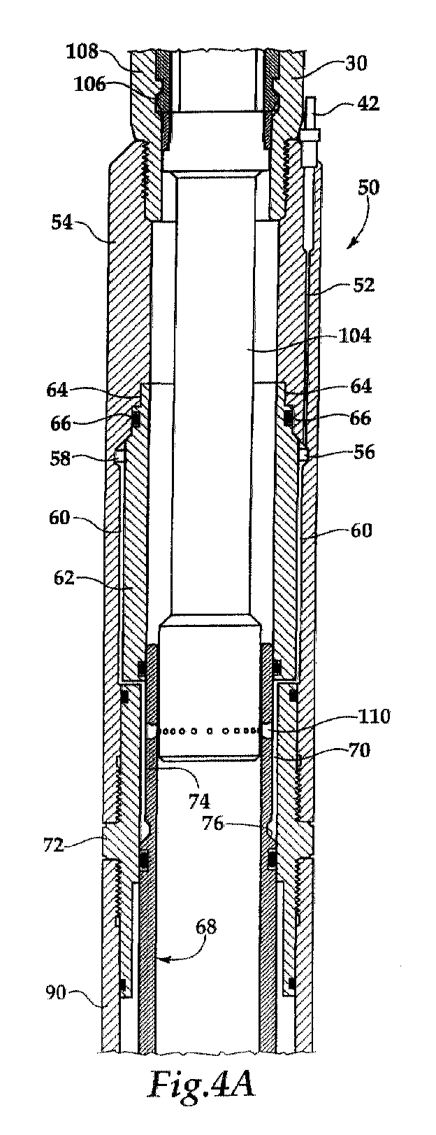
- Figure 4 is a half-section view of a tubing retrievable safety valve having a radial cutting tool positioned therein after creating a fluid passageway between the hydraulic chamber of the tubing retrievable safety valve and the interior of the tubing; and
- Figure 5 is a half-section view of a tubing retrievable safety valve having a wireline retrievable safety valve disposed therein such that hydraulic control over the wireline retrievable safety valve may be established with the hydraulic system originally utilized to control the tubing retrievable safety valve.
-
- Referring to Figure 1, an offshore oil and gas production platform having wireline retrievable safety valve lowered into a tubing retrievable safety valve is schematically illustrated and generally designated 10. A
semi-submersible platform 12 is centered over a submerged oil andgas formation 14 located belowsea floor 16.Wellhead 18 is located ondeck 20 ofplatform 12. Well 22 extends through the sea 24 and penetrates the various earthstrata including formation 14 to formwellbore 26. Disposed Within wellbore 26 is casing 28. Disposed withincasing 28 and extending fromwellhead 18 isproduction tubing 30. A pair ofseal assemblies tubing 30 andcasing 28 to prevent the flow of production fluids therebetween. During production, formation fluids enterwellbore 26 throughperforations 36 ofcasing 28 and travel intotubing 30 towellhead 18. - Coupled within
tubing 30 is a tubingretrievable safety valve 38. As is well known in the art, multiple tubing retrievable safety valves are commonly installed as part oftubing 30 to shut in production fromformation 14 in response to a variety of abnormal and potentially dangerous conditions. For convenience of illustration, however, only tubingretrievable safety valve 38 is shown. - Tubing
retrievable safety valve 38 is operated by hydraulic fluid pressure communicated thereto fromsurface installation 40 and hydraulicfluid control conduit 42. Hydraulic fluid pressure must be applied to tubingretrievable safety valve 38 to place tubingretrievable safety valve 38 in the open position. When hydraulic fluid pressure is lost, tubingretrievable safety valve 38 will operate to the closed position to prevent formation fluids from traveling therethrough. - If, for example, tubing
retrievable safety valve 38 is unable to properly seal in the closed position or does not properly open after being in the closed position, tubingretrievable safety valve 38 must typically be repaired or replaced. In the present invention, however, the functionality of tubingretrievable safety valve 38 may be replaced by wirelineretrievable safety valve 44, which may be installed within tubingretrievable safety valve 38 viawireline assembly 46 includingwireline 48. Once in place within tubingretrievable safety valve 38, wirelineretrievable safety valve 44 will be operated by hydraulic fluid pressure communicated thereto fromsurface installation 40 andhydraulic fluid line 42 through tubingretrievable safety valve 38. As with the original configuration of tubingretrievable safety valve 38, the hydraulic fluid pressure must be applied to wirelineretrievable safety valve 44 to place wirelineretrievable safety valve 44 in the open position. If hydraulic fluid pressure is lost, wirelineretrievable safety valve 44 will operate to the closed position to prevent formation fluids from traveling therethrough. - Even though Figure 1 depicts a cased vertical well, it should be noted by one skilled in the art that the present invention is equally well-suited for uncased wells, deviated wells or horizontal wells.
- Referring now to figures 2A and 2B, half sectional views of tubing
retrievable safety valve 50 are illustrated.Safety valve 50 is connected directly in series withproduction tubing 30. Hydraulic control pressure is conducted in communicated tosubsurface safety valve 50 viacontrol conduit 42 to alongitudinal bore 52 formed in the sidewall of thetop connector sub 54. Pressurized hydraulic fluid is delivered through thelongitudinal bore 52 into anannular chamber 56 defined by acounterbore 58 which is in communication with an annular undercut 60 formed in the sidewall of thetop connector sub 54. Aninner housing mandrel 62 is slidably coupled and sealed to thetop connector sub 54 by aslip union 64 andseal 66, with the undercut 60 defining an annulus betweeninner mandrel 62 and the sidewall oftop connector sub 54. - A
piston 68 is received in slidable, sealed engagement against the internal bore ofinner mandrel 62. The undercutannulus 60 opens into apiston chamber 70 in the annulus between the internal bore of aconnector sub 72 and the external surface ofpiston 68. The external radius of an uppersidewall piston section 74 is machined and reduced to define a radial clearance betweenpiston 68 andconnector sub 72. An annular slopingsurface 76 ofpiston 68 is acted against by the pressurized hydraulic fluid delivered throughcontrol conduit 42. In figures 2A-2B,piston 68 is in its locked out position whereinpiston 68 is fully extended with thepiston shoulder 78 engaging the topannular face 80 of anoperator tube 82. In this locked out position, areturn spring 84 is fully compressed. - A
flapper plate 86 is pivotally mounted onto ahinge sub 88 which is threadably connected to the lower end ofspring housing 90. Avalve seat 92 is confined within a counterbore formed onhinge sub 88. The lower end ofsafety valve 50 is connected toproduction tubing 30 by abottom sub connector 94. Thebottom sub connector 94 has acounterbore 96 which defines aflapper valve chamber 98. Thus, thebottom sub connector 94 forms a part of the flapper valve housing enclosure. In normal operation,flapper plate 86 pivots aboutpivot pin 100 and is biased to the valve closed position bycoil spring 102. Whensubsurface safety valve 50 must be operated from the valve open position to the valve closed position, hydraulic pressure is released fromconduit 42 such thatreturn spring 84 acts on the lower end ofpiston 68 which retractsoperator tube 82 longitudinally throughflapper valve chamber 98.Flapper closure plate 86 will then rotate throughchamber 98. In the locked out position as shown in figures 2A-2B, however, the spring bias force is overcome andflapper plate 86 is locked out byoperator tube 82. - Even though
subsurface safety valve 50 has been depicted, for the purposes of illustration, as having a flapper-type closure plate, it should be understood by one skilled in the art thatsubsurface safety valve 50 may incorporate various types of valve closure elements. Additionally, even thoughsubsurface safety valve 50 has been depicted, for the purposes of illustration, as having hydraulic fluid acting directly uponpiston 68, it should be understood by one skilled in the art thatsubsurface safety valve 50 may alternatively incorporate a rod-piston mechanism which is acted upon by the hydraulic fluid and which in turn operatespiston 68. - If
safety valve 50 becomes unable to properly seal in the closed position or does not properly open after being in the closed position, it is desirable to reestablish the functionality ofsafety valve 50 without removal oftubing 30. In the present invention, as depicted in figures 3A-3B, this is achieved by inserting aradial cutting tool 104 into the central bore ofsafety valve 50.Radial cutting tool 104 may use any one of several cutting techniques that are well known in the art including, but not limited to, chemical cutting, thermal cutting, mechanical cutting, explosive cutting or the like. - For example,
radial cutting tool 104 may be a chemical cutter that is lowered throughtubing 30 from the surface into the center of the locked outsafety valve 50. An example of a suitable chemical cutter is disclosed in U.S. Patent No. 5,575,331. The position ofradial cutting tool 104 withinsafety valve 50 is determined by the engagement of thelocator section 106 ofradial cutting tool 104 with alanding nipple 108 withintubing 30. Once in place,radial cutting tool 104 is operated to cut through uppersidewall piston section 74. In the case of using the chemical cutter, a dispersed jet of cutting fluid is released through cutting ports, making a 360 degree cut into the surrounding material. The chemical cutter is fired by an electrical signal carried by a cable, which is normally controlled at the surface. The depth of cut made by the chemical cutter is predetermined, and is controlled by the composition of chemicals loaded into the chemical cutter and the geometry of the cutting ports. The chemical cutter is set to make a cut deep enough to penetrate through uppersidewall piston section 74 of thepiston 68 while still shallow enough to maintain the integrity ofconnector sub 72, as best seen in figures 4A-4B. - With the use of any suitable
radial cutting tool 104, afluid passageway 110 is created frompiston chamber 70 to the interior ofsafety valve 50 through uppersidewall piston section 74. Hydraulic pressure communicated topiston chamber 70 may thereby be communicated to the interior ofsafety valve 50. Oncefluid passageway 110 is created through uppersidewall piston section 74,radial cutting tool 104 is retrieved to the surface. As depicted in figures 5A-5B, a wirelineretrievable safety valve 112 is then lowered into the central bore of tubingretrievable safety valve 50. Wireline retrievablevalve locator ring 115 engages landingnipple 108 withintubing 30 and locks into place. Installed in this manner,safety valve 112 seals the previouslyopen fluid passageway 110 created byradial cutting tool 104 betweenseal 114 andseal 116. Hydraulic control pressure is now conducted tosafety valve 112 throughfluid passageway 110. Pressurized hydraulic fluid may now be delivered through anannular chamber 118 defined betweenpiston 68 ofsafety valve 50 andhousing 120 ofsafety valve 112.Annular chamber 118 is in communication with aradial port 122 and anannular chamber 124 formed betweenhousing 120 andpiston 126 ofsafety valve 112.Piston 126 is slidably coupled and sealed tohousing 120 byseals Piston 126 is fully extended with thepiston shoulder 130 engaging the topannular face 132 of anoperator tube 134. In this valve open position, areturn spring 136 is fully compressed. - A
flapper plate 138 is pivotally mounted onto ahinge sub 140. Avalve seat 142 is confined withinhinge sub 140.Flapper plate 138 pivots aboutpivot pin 144 and is biased to the valve closed position bycoil spring 146. In the valve open position as shown in figures 5A-5B, the spring bias force is overcome andflapper plate 138 is retained in the valve open position byoperator tube 134 to permit formation fluid flow up throughtubing 30. - When an out of range condition occurs and
safety valve 112 must be operated from the valve open position to the valve closed position, hydraulic pressure is released fromconduit 44 such thatreturn spring 136 acts on the lower end ofpiston 126 which retractsoperator tube 134 longitudinally throughflapper valve chamber 148.Flapper closure plate 138 will then rotate throughchamber 148 and seal againstseat 142 to prevent the flow of formation fluids therethrough. As such,safety valve 112 replaces the functionality ofsafety valve 50 utilizing the hydraulic system originally used to operatesafety valve 50. Thus, with the use of the present invention, hydraulic control may be communicated to a wireline retrievable downhole device through an existing tubing retrievable downhole device without removal oftubing 30. In addition, with the use of the present invention, hydraulic control may be communicated to a wireline retrievable downhole device through an existing tubing retrievable downhole device without creating unnecessary leak paths or designing complex and expensive tubing retrievable downhole devices. - While this invention has been described with a reference to illustrative embodiments, this description is not intended to be construed in a limiting sense. Various modifications and combinations of the illustrative embodiments as well as other embodiments of the invention, will be apparent to persons skilled in the art upon reference to the description. It is, therefore, intended that the appended claims encompass any such modifications or embodiments.
Claims (10)
- A method for communicating hydraulic control from a tubing retrievable downhole device having a hydraulic chamber to a wireline retrievable downhole device, the method comprising the steps of: locating a radial cutting tool within the tubing retrievable downhole device; creating a fluid passageway from the hydraulic chamber to the interior of the tubing retrievable downhole device with the radial cutting tool; removing the radial cutting tool from the tubing retrievable downhole device; and positioning the wireline retrievable downhole device within the tubing retrievable downhole device adjacent to the fluid passageway, thereby communicating hydraulic control to the wireline retrievable downhole device.
- A method according to claim 1, wherein the step of creating a fluid passageway from the hydraulic chamber to the interior of the tubing retrievable downhole device with the radial cutting tool further comprises chemically cutting the fluid passageway.
- A method according to claim 1, wherein the step of creating a fluid passageway from the hydraulic chamber to the interior of the tubing retrievable downhole device with the radial cutting tool further comprises mechanically cutting the fluid passageway.
- A method for communicating hydraulic control to a wireline retrievable safety valve through a tubing retrievable safety valve, the method comprising the steps of: locating a radial cutting tool within the tubing retrievable safety valve; cutting a hole in the tubing retrievable safety valve with the radial cutting tool to create a fluid passageway from a hydraulic chamber of the tubing retrievable safety valve to the interior of the tubing retrievable safety valve; and positioning the wireline retrievable safety valve within the tubing retrievable safety valve; and applying a hydraulic pressure to the wireline retrievable safety valve through the tubing retrievable safety valve to actuate the wireline retrievable safety valve.
- A method according to claim 3, wherein the step of cutting a hole in the tubing retrievable safety valve further comprises chemically cutting the hole.
- A method according to claim 3, wherein the step of cutting a hole in the tubing retrievable safety valve further comprises mechanically cutting the hole.
- A system for communicating hydraulic control to a wireline retrievable downhole device comprising: a tubing retrievable downhole device having a hydraulic chamber; and a radial cutting tool selectively locatable within the tubing retrievable downhole device, the radial cutting tool creating a fluid passageway from the hydraulic chamber to the interior of the tubing retrievable downhole device such that when the wireline retrievable downhole device is positioned within the tubing retrievable downhole device hydraulic control is communicatable thereto through the fluid passageway.
- A system for communicating hydraulic control to a wireline retrievable safety valve comprising: a tubing retrievable safety valve having a hydraulic chamber; and a radial cutting tool selectively locatable within the tubing retrievable safety valve, the radial cutting tool cutting a hole in the tubing retrievable safety valve to create a fluid passageway from the hydraulic chamber to the interior of the tubing retrievable safety valve such that when the wireline retrievable safety valve is positioned within the tubing retrievable safety valve, application of a hydraulic pressure to the wireline retrievable safety valve through the tubing retrievable safety valve actuates the wireline retrievable safety valve.
- A system according to claim 7 or 8, wherein the radial cutting tool further comprises a chemical cutting tool.
- A system according to claim 7 or 8, wherein the radial cutting tool further comprises a mechanical cutting tool.
Applications Claiming Priority (2)
| Application Number | Priority Date | Filing Date | Title |
|---|---|---|---|
| US09/540,002 US6352118B1 (en) | 2000-03-30 | 2000-03-30 | System and method for communication hydraulic control to a wireline retrievable downhole device |
| US540002 | 2000-03-30 |
Publications (2)
| Publication Number | Publication Date |
|---|---|
| EP1138873A1 true EP1138873A1 (en) | 2001-10-04 |
| EP1138873B1 EP1138873B1 (en) | 2005-08-03 |
Family
ID=24153557
Family Applications (1)
| Application Number | Title | Priority Date | Filing Date |
|---|---|---|---|
| EP01303045A Expired - Lifetime EP1138873B1 (en) | 2000-03-30 | 2001-03-30 | System and method for communicating hydraulic control to a wireline retrievable downhole safety valve |
Country Status (3)
| Country | Link |
|---|---|
| US (1) | US6352118B1 (en) |
| EP (1) | EP1138873B1 (en) |
| DE (1) | DE60112350D1 (en) |
Cited By (4)
| Publication number | Priority date | Publication date | Assignee | Title |
|---|---|---|---|---|
| GB2390106B (en) * | 2002-06-24 | 2005-11-30 | Schlumberger Holdings | Apparatus and methods for establishing secondary hydraulics in a downhole tool |
| CN102080512A (en) * | 2011-01-05 | 2011-06-01 | 深圳市远东石油钻采工程有限公司 | Multiposition one-way bypass connection structure for deep-water abandoned well cutting device |
| WO2021032689A1 (en) * | 2019-08-21 | 2021-02-25 | Fmc Kongsberg Subsea As | Method of operating a subsea production system, a subsea tree and an electric downhole safety valve |
| CN112855061A (en) * | 2021-01-12 | 2021-05-28 | 中国矿业大学 | Hydraulic cutting recovery system and method for ground gas extraction shear failure drilling |
Families Citing this family (22)
| Publication number | Priority date | Publication date | Assignee | Title |
|---|---|---|---|---|
| US6722440B2 (en) * | 1998-08-21 | 2004-04-20 | Bj Services Company | Multi-zone completion strings and methods for multi-zone completions |
| US6619388B2 (en) * | 2001-02-15 | 2003-09-16 | Halliburton Energy Services, Inc. | Fail safe surface controlled subsurface safety valve for use in a well |
| US6644411B2 (en) * | 2001-04-18 | 2003-11-11 | Kvaerner Oilfield Products, Inc. | Tubing hanger with flapper valve |
| US6523614B2 (en) * | 2001-04-19 | 2003-02-25 | Halliburton Energy Services, Inc. | Subsurface safety valve lock out and communication tool and method for use of the same |
| US6988556B2 (en) * | 2002-02-19 | 2006-01-24 | Halliburton Energy Services, Inc. | Deep set safety valve |
| US6991040B2 (en) * | 2002-07-12 | 2006-01-31 | Weatherford/Lamb, Inc. | Method and apparatus for locking out a subsurface safety valve |
| US7188674B2 (en) * | 2002-09-05 | 2007-03-13 | Weatherford/Lamb, Inc. | Downhole milling machine and method of use |
| CA2636887C (en) * | 2003-10-27 | 2012-03-13 | Baker Hughes Incorporated | Tubing retrievable safety valve and method |
| US7640989B2 (en) * | 2006-08-31 | 2010-01-05 | Halliburton Energy Services, Inc. | Electrically operated well tools |
| US8038120B2 (en) | 2006-12-29 | 2011-10-18 | Halliburton Energy Services, Inc. | Magnetically coupled safety valve with satellite outer magnets |
| US8919730B2 (en) | 2006-12-29 | 2014-12-30 | Halliburton Energy Services, Inc. | Magnetically coupled safety valve with satellite inner magnets |
| US7918280B2 (en) | 2007-02-13 | 2011-04-05 | Baker Hughes Incorporated | Radial indexing communication tool and method for subsurface safety valve with communication component |
| MY148059A (en) * | 2007-02-13 | 2013-02-28 | Bj Services Co | Tool and method for establishing hydraulic communication with a subsurface safety valve |
| NO333099B1 (en) * | 2008-11-03 | 2013-03-04 | Statoil Asa | Process for modifying an existing subsea oil well and a modified oil well |
| US8573304B2 (en) | 2010-11-22 | 2013-11-05 | Halliburton Energy Services, Inc. | Eccentric safety valve |
| US8511374B2 (en) | 2011-08-02 | 2013-08-20 | Halliburton Energy Services, Inc. | Electrically actuated insert safety valve |
| US8490687B2 (en) | 2011-08-02 | 2013-07-23 | Halliburton Energy Services, Inc. | Safety valve with provisions for powering an insert safety valve |
| US9470064B2 (en) * | 2013-12-17 | 2016-10-18 | Baker Hughes Incorporated | Safety valve, downhole system having safety valve, and method |
| US10472929B2 (en) * | 2017-01-25 | 2019-11-12 | Baker Hughes, A Ge Company, Llc | Tubular isolation valve resettable lock open mechanism |
| US10920529B2 (en) | 2018-12-13 | 2021-02-16 | Tejas Research & Engineering, Llc | Surface controlled wireline retrievable safety valve |
| SG11202101329PA (en) * | 2018-12-28 | 2021-03-30 | Halliburton Energy Services Inc | Insert safety valve |
| US11661826B2 (en) * | 2021-04-28 | 2023-05-30 | Halliburton Energy Services, Inc. | Well flow control using delayed secondary safety valve |
Citations (7)
| Publication number | Priority date | Publication date | Assignee | Title |
|---|---|---|---|---|
| US3696868A (en) * | 1970-12-18 | 1972-10-10 | Otis Eng Corp | Well flow control valves and well systems utilizing the same |
| US3763932A (en) * | 1971-12-27 | 1973-10-09 | Brown Oil Tools | Surface operated, subsurface safety valve assembly |
| US4944351A (en) * | 1989-10-26 | 1990-07-31 | Baker Hughes Incorporated | Downhole safety valve for subterranean well and method |
| US4981177A (en) * | 1989-10-17 | 1991-01-01 | Baker Hughes Incorporated | Method and apparatus for establishing communication with a downhole portion of a control fluid pipe |
| US5249630A (en) * | 1992-01-21 | 1993-10-05 | Otis Engineering Corporation | Perforating type lockout tool |
| US5496044A (en) * | 1993-03-24 | 1996-03-05 | Baker Hughes Incorporated | Annular chamber seal |
| US5575331A (en) * | 1995-06-07 | 1996-11-19 | Halliburton Company | Chemical cutter |
Family Cites Families (4)
| Publication number | Priority date | Publication date | Assignee | Title |
|---|---|---|---|---|
| US4606410A (en) * | 1983-04-06 | 1986-08-19 | Bst Lift Systems, Inc. | Subsurface safety system |
| US4603740A (en) * | 1984-08-29 | 1986-08-05 | Hydril Company | Subsurface safety valve |
| US4605070A (en) * | 1985-04-01 | 1986-08-12 | Camco, Incorporated | Redundant safety valve system and method |
| US5314026A (en) * | 1992-03-04 | 1994-05-24 | Otis Engineering Corporation | Landing nipple |
-
2000
- 2000-03-30 US US09/540,002 patent/US6352118B1/en not_active Expired - Lifetime
-
2001
- 2001-03-30 DE DE60112350T patent/DE60112350D1/en not_active Expired - Lifetime
- 2001-03-30 EP EP01303045A patent/EP1138873B1/en not_active Expired - Lifetime
Patent Citations (7)
| Publication number | Priority date | Publication date | Assignee | Title |
|---|---|---|---|---|
| US3696868A (en) * | 1970-12-18 | 1972-10-10 | Otis Eng Corp | Well flow control valves and well systems utilizing the same |
| US3763932A (en) * | 1971-12-27 | 1973-10-09 | Brown Oil Tools | Surface operated, subsurface safety valve assembly |
| US4981177A (en) * | 1989-10-17 | 1991-01-01 | Baker Hughes Incorporated | Method and apparatus for establishing communication with a downhole portion of a control fluid pipe |
| US4944351A (en) * | 1989-10-26 | 1990-07-31 | Baker Hughes Incorporated | Downhole safety valve for subterranean well and method |
| US5249630A (en) * | 1992-01-21 | 1993-10-05 | Otis Engineering Corporation | Perforating type lockout tool |
| US5496044A (en) * | 1993-03-24 | 1996-03-05 | Baker Hughes Incorporated | Annular chamber seal |
| US5575331A (en) * | 1995-06-07 | 1996-11-19 | Halliburton Company | Chemical cutter |
Cited By (7)
| Publication number | Priority date | Publication date | Assignee | Title |
|---|---|---|---|---|
| GB2390106B (en) * | 2002-06-24 | 2005-11-30 | Schlumberger Holdings | Apparatus and methods for establishing secondary hydraulics in a downhole tool |
| CN102080512A (en) * | 2011-01-05 | 2011-06-01 | 深圳市远东石油钻采工程有限公司 | Multiposition one-way bypass connection structure for deep-water abandoned well cutting device |
| CN102080512B (en) * | 2011-01-05 | 2013-03-20 | 深圳市远东石油钻采工程有限公司 | Multiposition one-way bypass connection structure for deep-water abandoned well cutting device |
| WO2021032689A1 (en) * | 2019-08-21 | 2021-02-25 | Fmc Kongsberg Subsea As | Method of operating a subsea production system, a subsea tree and an electric downhole safety valve |
| US11920427B2 (en) | 2019-08-21 | 2024-03-05 | Fmc Kongsberg Subsea As | Method of operating a subsea production system, a subsea tree and an electric downhole safety valve |
| CN112855061A (en) * | 2021-01-12 | 2021-05-28 | 中国矿业大学 | Hydraulic cutting recovery system and method for ground gas extraction shear failure drilling |
| CN112855061B (en) * | 2021-01-12 | 2021-11-19 | 中国矿业大学 | Hydraulic cutting recovery system and method for ground gas extraction shear failure drilling |
Also Published As
| Publication number | Publication date |
|---|---|
| DE60112350D1 (en) | 2005-09-08 |
| EP1138873B1 (en) | 2005-08-03 |
| US6352118B1 (en) | 2002-03-05 |
Similar Documents
| Publication | Publication Date | Title |
|---|---|---|
| EP1138873B1 (en) | System and method for communicating hydraulic control to a wireline retrievable downhole safety valve | |
| US7249635B2 (en) | Communication tool for accessing a non annular hydraulic chamber of a subsurface safety valve | |
| CA2633226C (en) | Method and apparatus to hydraulically bypass a well tool | |
| US7631699B2 (en) | System and method for pressure isolation for hydraulically actuated tools | |
| EP1828537B1 (en) | Method and apparatus to hydraulically bypass a well tool | |
| EP0682169A2 (en) | Pressur operated apparatus for use in high pressure well | |
| EP0470160B1 (en) | Well control apparatus | |
| US20200056714A1 (en) | Deep set production tubing pressure insensitive wireline retrievable safety valve | |
| EP2719856B1 (en) | Seal assembly for subsurface safety valve | |
| WO2003048516A1 (en) | Pilot valve |
Legal Events
| Date | Code | Title | Description |
|---|---|---|---|
| PUAI | Public reference made under article 153(3) epc to a published international application that has entered the european phase |
Free format text: ORIGINAL CODE: 0009012 |
|
| AK | Designated contracting states |
Kind code of ref document: A1 Designated state(s): AT BE CH CY DE DK ES FI FR GB GR IE IT LI LU MC NL PT SE TR |
|
| AX | Request for extension of the european patent |
Free format text: AL;LT;LV;MK;RO;SI |
|
| 17P | Request for examination filed |
Effective date: 20020201 |
|
| AKX | Designation fees paid |
Free format text: DE FR GB NL |
|
| 17Q | First examination report despatched |
Effective date: 20021010 |
|
| RTI1 | Title (correction) |
Free format text: SYSTEM AND METHOD FOR COMMUNICATING HYDRAULIC CONTROL TO A WIRELINE RETRIEVABLE DOWNHOLE SAFETY VALVE |
|
| GRAP | Despatch of communication of intention to grant a patent |
Free format text: ORIGINAL CODE: EPIDOSNIGR1 |
|
| GRAS | Grant fee paid |
Free format text: ORIGINAL CODE: EPIDOSNIGR3 |
|
| GRAA | (expected) grant |
Free format text: ORIGINAL CODE: 0009210 |
|
| AK | Designated contracting states |
Kind code of ref document: B1 Designated state(s): DE FR GB NL |
|
| PG25 | Lapsed in a contracting state [announced via postgrant information from national office to epo] |
Ref country code: NL Free format text: LAPSE BECAUSE OF FAILURE TO SUBMIT A TRANSLATION OF THE DESCRIPTION OR TO PAY THE FEE WITHIN THE PRESCRIBED TIME-LIMIT Effective date: 20050803 |
|
| REG | Reference to a national code |
Ref country code: GB Ref legal event code: FG4D |
|
| REF | Corresponds to: |
Ref document number: 60112350 Country of ref document: DE Date of ref document: 20050908 Kind code of ref document: P |
|
| PG25 | Lapsed in a contracting state [announced via postgrant information from national office to epo] |
Ref country code: DE Free format text: LAPSE BECAUSE OF FAILURE TO SUBMIT A TRANSLATION OF THE DESCRIPTION OR TO PAY THE FEE WITHIN THE PRESCRIBED TIME-LIMIT Effective date: 20051104 |
|
| NLV1 | Nl: lapsed or annulled due to failure to fulfill the requirements of art. 29p and 29m of the patents act | ||
| ET | Fr: translation filed | ||
| PLBE | No opposition filed within time limit |
Free format text: ORIGINAL CODE: 0009261 |
|
| STAA | Information on the status of an ep patent application or granted ep patent |
Free format text: STATUS: NO OPPOSITION FILED WITHIN TIME LIMIT |
|
| 26N | No opposition filed |
Effective date: 20060504 |
|
| REG | Reference to a national code |
Ref country code: FR Ref legal event code: PLFP Year of fee payment: 15 |
|
| PGFP | Annual fee paid to national office [announced via postgrant information from national office to epo] |
Ref country code: GB Payment date: 20150224 Year of fee payment: 15 Ref country code: FR Payment date: 20150224 Year of fee payment: 15 |
|
| GBPC | Gb: european patent ceased through non-payment of renewal fee |
Effective date: 20160330 |
|
| REG | Reference to a national code |
Ref country code: FR Ref legal event code: ST Effective date: 20161130 |
|
| PG25 | Lapsed in a contracting state [announced via postgrant information from national office to epo] |
Ref country code: GB Free format text: LAPSE BECAUSE OF NON-PAYMENT OF DUE FEES Effective date: 20160330 Ref country code: FR Free format text: LAPSE BECAUSE OF NON-PAYMENT OF DUE FEES Effective date: 20160331 |