EP1138854A1 - Door lock apparatus for vehicles - Google Patents
Door lock apparatus for vehicles Download PDFInfo
- Publication number
- EP1138854A1 EP1138854A1 EP20010104262 EP01104262A EP1138854A1 EP 1138854 A1 EP1138854 A1 EP 1138854A1 EP 20010104262 EP20010104262 EP 20010104262 EP 01104262 A EP01104262 A EP 01104262A EP 1138854 A1 EP1138854 A1 EP 1138854A1
- Authority
- EP
- European Patent Office
- Prior art keywords
- latch
- unit
- sublever
- link
- lever
- Prior art date
- Legal status (The legal status is an assumption and is not a legal conclusion. Google has not performed a legal analysis and makes no representation as to the accuracy of the status listed.)
- Granted
Links
- 230000005540 biological transmission Effects 0.000 description 2
- 230000015572 biosynthetic process Effects 0.000 description 1
- 230000003449 preventive effect Effects 0.000 description 1
Images



Classifications
-
- E—FIXED CONSTRUCTIONS
- E05—LOCKS; KEYS; WINDOW OR DOOR FITTINGS; SAFES
- E05B—LOCKS; ACCESSORIES THEREFOR; HANDCUFFS
- E05B77/00—Vehicle locks characterised by special functions or purposes
- E05B77/22—Functions related to actuation of locks from the passenger compartment of the vehicle
- E05B77/24—Functions related to actuation of locks from the passenger compartment of the vehicle preventing use of an inner door handle, sill button, lock knob or the like
- E05B77/28—Functions related to actuation of locks from the passenger compartment of the vehicle preventing use of an inner door handle, sill button, lock knob or the like for anti-theft purposes, e.g. double-locking or super-locking
-
- E—FIXED CONSTRUCTIONS
- E05—LOCKS; KEYS; WINDOW OR DOOR FITTINGS; SAFES
- E05B—LOCKS; ACCESSORIES THEREFOR; HANDCUFFS
- E05B81/00—Power-actuated vehicle locks
- E05B81/02—Power-actuated vehicle locks characterised by the type of actuators used
- E05B81/04—Electrical
-
- E—FIXED CONSTRUCTIONS
- E05—LOCKS; KEYS; WINDOW OR DOOR FITTINGS; SAFES
- E05B—LOCKS; ACCESSORIES THEREFOR; HANDCUFFS
- E05B81/00—Power-actuated vehicle locks
- E05B81/12—Power-actuated vehicle locks characterised by the function or purpose of the powered actuators
- E05B81/16—Power-actuated vehicle locks characterised by the function or purpose of the powered actuators operating on locking elements for locking or unlocking action
-
- E—FIXED CONSTRUCTIONS
- E05—LOCKS; KEYS; WINDOW OR DOOR FITTINGS; SAFES
- E05B—LOCKS; ACCESSORIES THEREFOR; HANDCUFFS
- E05B77/00—Vehicle locks characterised by special functions or purposes
- E05B77/22—Functions related to actuation of locks from the passenger compartment of the vehicle
- E05B77/24—Functions related to actuation of locks from the passenger compartment of the vehicle preventing use of an inner door handle, sill button, lock knob or the like
- E05B77/26—Functions related to actuation of locks from the passenger compartment of the vehicle preventing use of an inner door handle, sill button, lock knob or the like specially adapted for child safety
Definitions
- the present invention relates to a door lock apparatus for vehicles, particularly to a door lock apparatus for locking and unlocking a slide door to a body of an automobile.
- the conventional door locking and unlocking apparatus includes a pair of front and rear latch units 103 having latches engaged with strikers of a vehicle body for maintaining a vehicular door in a closed state relative to the vehicle body, handle units 106 and 107 on an inner side and an outer side of the vehicular door for operating the latch units 103 to bring the door into an opened state or a closed state relative to the vehicle body, and a remote control unit 104 for making operation of the handle units 106 and 107 transmittable or nontransmittable to the latch units 103.
- the latch units 103 each is constituted by a structure having a rotatable latch engaging to and disengaging from the striker of the vehicle body, a rotatable pawl engaged with the latch for restricting rotation of the latch and a main lever for operating the pawl.
- unlatch operation of the latch units 103 is carried out by operating main levers of the latch units 103 via the open lever and the lift lever of the remote control unit 104 by operating the handle unit 106 and 107.
- lock operation of the latch units 103 is carried out by releasing engagement of the open lever and the lift lever of the remote control unit 104 by operating the locking lever of the remote control unit 104 by operating a sill knob provided on the compartment inner side of the vehicular door or a key cylinder provided on the compartment outer side.
- the latch units are operated to unlock by operating the remote control unit, as a result, the unlatch operation of the latch units can be carried out by operating the handle units and there is the danger of opening the door.
- a door lock apparatus for vehicles having a latch unit having a latch engaged with a striker of a vehicle body for maintaining a vehicular door in a closed state relative to the vehicle body, a handle unit for operating the latch unit to bring the vehicular door into an opened state relative to the vehicle body and a remote control unit for making operation of the handle unit transmittable or nontransmittable to the latch unit,
- the vehicular door locking and unlocking apparatus comprising a main lever provided at the latch unit for operating a pawl for restricting rotation of the latch, and a sublever provided to the latch unit, transmitting the operation of the handle unit via the remote control unit and engageable to and disengageable from the main lever.
- the lock operation of the latch unit per se is carried out. Therefore, even when cables or rods for connecting and engaging the remote control unit and the latch unit are unlawfully operated or even when the latch unit is unlawfully operated to unlock by unlawful operation of the remote control unit, by lock operation of the latch unit per se, the latch unit can be prevented from being operated to unlatch and robbery preventive performance can be promoted.
- the door lock apparatus further comprising an actuator provided to the latch unit, a first link provided to the latch unit and pivoted by operation of the actuator, and a second link which is provided to the latch unit, one end of which is axially supported by the first link and other end of which is capable of being brought into contact with a portion of the sublever, wherein the actuator releases contact between the sublever and the second link and releases engagement between the main lever and the sublever.
- the door lock apparatus further comprising a bracket for coaxially and pivotably supporting the sublever and the main lever and holding the actuator, wherein the main lever, the sublever, the first and the second links and a portion of the actuator are surrounded by the bracket.
- a slide door 101 of a vehicle is arranged with the pair of front and rear latch units 103 for maintaining a slide door 101 in a closed state relative to a vehicle body 102 and a remote control unit 104 for operating the latch units 103.
- the remote control unit 104 and the pair of front and rear latch units 103 are connected and engaged with each other by cables and rods arranged to the slide door 101, further, the remote control unit 104 is connected and engaged with a outside handle unit 107 arranged on a panel of the compartment outer side of the slide door 101 and the inside handle unit 106 arranged on a panel of the compartment inner side of the slide door 101.
- the remote control unit 104 is mainly constituted by a lift lever 41, an inside open lever 42 and an outside open lever 43.
- the inside open lever 42 is pivotably supported by the coaxial shaft 93 provided at a base bracket 91 and is connected to an inside handle of the inside handle unit 106 via a rod 61a at one end thereof.
- a slide bush 48 is slidably supported.
- the outside open lever 43 is pivotably supported by the coaxial shaft 93 at one end thereof and is connected to an outside handle of the outside handle unit 107 via a cable 43e at other end thereof.
- the outside open lever 43 is engageably and disengageably arranged with engaging and disengaging pin portions 47a and 48a of the slide bushes 47 and 48.
- the slide bush 47 is made to slide by a locking lever 44.
- the locking lever 44 is pivotably supported by the base bracket 91 by snap engagement and is inserted with a connecting pin portion 47b of the slide bush 47.
- the locking lever 44 is connected to an output lever 51 of a locking actuator 50 attached to the base bracket 91. Further, the output lever 51 is connected to a sill knob of the inside handle unit 106 via a rod 62a.
- the slide bush 48 is made to slide by a connecting lever 49.
- the connecting lever 49 is pivotably supported by the base bracket 91 by snap engagement and is inserted with the engaging and disengaging pin portion 48a of the slide bush 48.
- the connecting lever 49 is connected to a child lever of the inside handle unit 106.
- the main lever 3 is provided at its center portion with a hole 6 for inserting a pin 2 and at its one end with a long hole 7 extending longitudinally.
- An end portion 8 of the main lever 3 on a side opposed to the end portion having the long hole 7 is capable of being brought into contact with an operating lever 9 connected to a pawl 18 of the latch unit 103.
- the sublever 4 supported by the pin 2 is formed substantially in a T-like shape and is provided with a hole 10 for passing the pin 2, a piece 12 for fixing one end of the cable 11 and a contact piece 13 capable of being brought into contact with a second link 15, mentioned later.
- first link 14 which is made pivotable by an output shaft of an actuator 5, is axially supported by one end of the second link 15.
- the other end of the second link 15 is provided with a contact portion 16 capable of being brought into contact with the contact piece 13 of the sublever 4 and a projected portion 17 (or pin) inserted into the long hole 7.
- bracket 1 is constituted by a box shape surrounding the main lever 3, the sublever 4, the first and the second links 14 and 15 and a portion of the actuator 5 to thereby prohibit unlawful approach to these parts from outside.
- the actuator 5 In a lock state of the latch unit 103 by operating the locking lever 44 of the remote control unit 104, by an electric signal from an ignition key having an operating button for operating door lock apparatus of respective doors of the vehicle in wireless, an electric signal in cooperation with double lock operation of a door lock apparatus of a door on the driver's seat side or the like, the actuator 5 is operated and pivots the first link 14 in the counterclockwise direction of Fig. 2.
- the first link 14 By pivoting the first link 14 in the counterclockwise direction of Fig. 2, as shown by Fig. 3, the projected portion 17 of the second link 15 is moved along the long hole 7 of the main lever 3 and the contact portion 16 is moved to a position separated from the contact piece 13 of the sublever 4 (double lock operation of latch unit 103) .
- the actuator 5 is operated and the first link 14 is pivoted in the counterclockwise direction of Fig. 3.
- the second link 15 is moved along the long hole 7 and the normal state shown by Fig. 2 can be provided.
- a spring may be arranged pertinently to maintain the state of Fig. 2.
- a contact portion (16) of a second link (15) opposed to a contact piece (13) of a sublever (4) is moved to other position by operating an actuator (5) to thereby release the opposed relationship.
Landscapes
- Lock And Its Accessories (AREA)
Abstract
Description
- The present invention relates to a door lock apparatus for vehicles, particularly to a door lock apparatus for locking and unlocking a slide door to a body of an automobile.
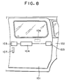
- Conventionally, there is known a door lock apparatus for vehicles of this kind as disclosed in Japanese Patent Laid-Open Publication No.24737/1998. As shown in Fig. 8, the conventional door locking and unlocking apparatus includes a pair of front and
rear latch units 103 having latches engaged with strikers of a vehicle body for maintaining a vehicular door in a closed state relative to the vehicle body,handle units latch units 103 to bring the door into an opened state or a closed state relative to the vehicle body, and aremote control unit 104 for making operation of thehandle units latch units 103. - The
latch units 103 each is constituted by a structure having a rotatable latch engaging to and disengaging from the striker of the vehicle body, a rotatable pawl engaged with the latch for restricting rotation of the latch and a main lever for operating the pawl. - The
remote control unit 104 is constituted by a structure having an open lever connected and engaged with thehandle units latch units 103 and capable of engaging to and disengaging from the open lever and a locking lever engaging to and disengaging from the open lever and the lift lever. - Further, unlatch operation of the
latch units 103 is carried out by operating main levers of thelatch units 103 via the open lever and the lift lever of theremote control unit 104 by operating thehandle unit latch units 103 is carried out by releasing engagement of the open lever and the lift lever of theremote control unit 104 by operating the locking lever of theremote control unit 104 by operating a sill knob provided on the compartment inner side of the vehicular door or a key cylinder provided on the compartment outer side. - The lift lever of the
remote control unit 104 and the main levers of thelatch units 103 are coupled by cables and rods arranged in the vehicular door, and thereby theremote control unit 104 and thelatch units 103 are connected and engaged with each other. - According to the above-described constitution, operations of lock and unlock of the door as well as latch and unlatch of the
latch units 103 are carried out by theremote control unit 104. However, since theremote control unit 104 and thelatch units 103 are coupled by cables and rods, when the cables and the rods are unlawfully operated from outside of the vehicle, there is a danger of opening the door by operating the latch units to unlatch regardless of operating the latch units to lock by operating the remote control unit. - Further, when the sill knob is unlawfully operated from outside of the vehicle, the latch units are operated to unlock by operating the remote control unit, as a result, the unlatch operation of the latch units can be carried out by operating the handle units and there is the danger of opening the door.
- Hence, it is an object of the invention to resolve the drawback of the conventional technology, mentioned above.
- According to the invention, in order to resolve the above-described problem, basically, a technical conception for arranging a sublever engageable to and disengageable from a main lever at a latch unit is employed.
- Specifically, according to an aspect of invention, there is provided a door lock apparatus for vehicles having a latch unit having a latch engaged with a striker of a vehicle body for maintaining a vehicular door in a closed state relative to the vehicle body, a handle unit for operating the latch unit to bring the vehicular door into an opened state relative to the vehicle body and a remote control unit for making operation of the handle unit transmittable or nontransmittable to the latch unit, the vehicular door locking and unlocking apparatus comprising a main lever provided at the latch unit for operating a pawl for restricting rotation of the latch, and a sublever provided to the latch unit, transmitting the operation of the handle unit via the remote control unit and engageable to and disengageable from the main lever.
- According to the present apparatus, by releasing engagement between the main lever and the sublever, in addition to lock operation of the latch unit by operating the remote control unit, the lock operation of the latch unit per se is carried out. Therefore, even when cables or rods for connecting and engaging the remote control unit and the latch unit are unlawfully operated or even when the latch unit is unlawfully operated to unlock by unlawful operation of the remote control unit, by lock operation of the latch unit per se, the latch unit can be prevented from being operated to unlatch and robbery preventive performance can be promoted.
- More preferably, according to another aspect of invention, there is provided the door lock apparatus, further comprising an actuator provided to the latch unit, a first link provided to the latch unit and pivoted by operation of the actuator, and a second link which is provided to the latch unit, one end of which is axially supported by the first link and other end of which is capable of being brought into contact with a portion of the sublever, wherein the actuator releases contact between the sublever and the second link and releases engagement between the main lever and the sublever.
- More preferably, according to further another aspect of the invention, there is provided the door lock apparatus, further comprising a long hole formed in the main lever and a projected pin formed at the second link and inserted into the long hole of the main lever and capable of being brought into contact with a portion of the sublever, wherein by operating the actuator, the projected pin of the second link is moved along the long hole by the first link and the contact relationship between the second link and the sublever is released.
- More preferably, according to another aspect of the invention, there is provided the door lock apparatus, further comprising a bracket for coaxially and pivotably supporting the sublever and the main lever and holding the actuator, wherein the main lever, the sublever, the first and the second links and a portion of the actuator are surrounded by the bracket.
-
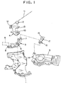
- Fig. 1 is a disassembled perspective view of a latch unit of a door lock apparatus according to the invention;
- Fig. 2 is a front view of the latch unit of the door lock apparatus according to the invention;
- Fig. 3 is a front view showing a double lock operation of the latch unit of the door lock apparatus according to the invention;
- Fig. 4 is a front view of a vehicular door mounted with the door lock apparatus according to the invention;
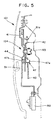
- Fig. 5 is a sectional view showing a remote control unit of the door lock apparatus according to the invention;
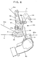
- Fig. 6 is a sectional view showing the remote control unit of the door lock apparatus according to the invention;
- Fig. 7 is a perspective view of each parts for the remote control unit according to the invention; and
- Fig. 8 is a front view of a vehicular door mounted with a conventional door locking and unlocking apparatus.
-
- As shown by Fig. 4, a
slide door 101 of a vehicle is arranged with the pair of front andrear latch units 103 for maintaining aslide door 101 in a closed state relative to avehicle body 102 and aremote control unit 104 for operating thelatch units 103. - The
remote control unit 104 and the pair of front andrear latch units 103 are connected and engaged with each other by cables and rods arranged to theslide door 101, further, theremote control unit 104 is connected and engaged with aoutside handle unit 107 arranged on a panel of the compartment outer side of theslide door 101 and theinside handle unit 106 arranged on a panel of the compartment inner side of theslide door 101. - As shown by Fig. 5 - 7 the
remote control unit 104 is mainly constituted by alift lever 41, an insideopen lever 42 and an outsideopen lever 43. - The
lift lever 41 is pivotably supported by acoaxial shaft 93 at a central portion in the longitudinal direction thereof and coupled tosublevers 4 of thelatch units 103, mentioned later, bycables 11 at both ends thereof. Aslide bush 47 is slidably supported by thelift lever 41. - The inside
open lever 42 is pivotably supported by thecoaxial shaft 93 provided at abase bracket 91 and is connected to an inside handle of theinside handle unit 106 via arod 61a at one end thereof. At other end of the insideopen lever 42, aslide bush 48 is slidably supported. - The outside
open lever 43 is pivotably supported by thecoaxial shaft 93 at one end thereof and is connected to an outside handle of theoutside handle unit 107 via acable 43e at other end thereof. The outsideopen lever 43 is engageably and disengageably arranged with engaging and disengagingpin portions slide bushes - The
slide bush 47 is made to slide by alocking lever 44. Thelocking lever 44 is pivotably supported by thebase bracket 91 by snap engagement and is inserted with a connectingpin portion 47b of theslide bush 47. Thelocking lever 44 is connected to anoutput lever 51 of alocking actuator 50 attached to thebase bracket 91. Further, theoutput lever 51 is connected to a sill knob of theinside handle unit 106 via arod 62a. - The
slide bush 48 is made to slide by a connectinglever 49. The connectinglever 49 is pivotably supported by thebase bracket 91 by snap engagement and is inserted with the engaging and disengagingpin portion 48a of theslide bush 48. The connectinglever 49 is connected to a child lever of theinside handle unit 106. - In a state shown by Fig. 6, when the
inside handle unit 106 or theoutside handle unit 107 is operated, thelift lever 41 is pivoted via the insideopen lever 42, the outsideopen lever 43 and theslide bushes handle unit lift lever 41 of theremote control unit 104 to thesublevers 4 of thelatch units 103 via the cables 11 (unlatch operation of latch unit 103). - In the state shown by Fig. 6, when the
locking lever 44 is operated by the sill knob or thelocking actuator 50, theslide bush 47 is made to slide and engagement between the outsideopen lever 43 and thelift lever 41 via theslide bush 47 is released. Under the state, ever when theinside handle unit 106 or theoutside handle unit 107 is operated, thelift lever 41 is not pivoted, thereby, operation of thehandle unit lift lever 41 of theremote control unit 104 to thesublevers 4 of thelatch units 103 via the cables 11 (lock operation of latch unit 103). - As shown by Fig. 1 and Fig. 2, the
latch unit 103 is mainly constituted by amain lever 3 and thesublever 4. - The
main lever 3 is provided at its center portion with ahole 6 for inserting apin 2 and at its one end with along hole 7 extending longitudinally. Anend portion 8 of themain lever 3 on a side opposed to the end portion having thelong hole 7 is capable of being brought into contact with anoperating lever 9 connected to apawl 18 of thelatch unit 103. - The
sublever 4 supported by thepin 2 is formed substantially in a T-like shape and is provided with ahole 10 for passing thepin 2, apiece 12 for fixing one end of thecable 11 and acontact piece 13 capable of being brought into contact with asecond link 15, mentioned later. - One end of a
first link 14 which is made pivotable by an output shaft of anactuator 5, is axially supported by one end of thesecond link 15. The other end of thesecond link 15 is provided with acontact portion 16 capable of being brought into contact with thecontact piece 13 of thesublever 4 and a projected portion 17 (or pin) inserted into thelong hole 7. - Although in the illustrated example, a lower half portion of a bracket 1 is shown, the bracket 1 is constituted by a box shape surrounding the
main lever 3, thesublever 4, the first and thesecond links actuator 5 to thereby prohibit unlawful approach to these parts from outside. - Fig. 2 shows a state for normal latch and unlatch operations. The
contact piece 13 of thesublever 4 is opposed to thecontact portion 16 of thesecond link 15, the projectedportion 17 is disposed at one end of thelong hole 7 and theend portion 8 of themain lever 3 is opposed to theoperating lever 9. - The
operating lever 9 is coupled to thepawl 18 of thelatch unit 103. Thepawl 18 is engaged with and disengaged from aratchet 19 for receiving a striker on the vehicle body side and specifies positions of the ratchet 19 (latch and unlatch positions). - In the state shown by Fig. 2, when the
cable 11 is pulled in an arrow mark A direction by pivoting thelift lever 41 of theremote control unit 104 by operating theoutside handle unit 107 or theinside handle unit 106, thesublever 4 is pivoted in the clockwise direction centering on thepin 2, thecontact piece 13 of thesecond link 15 pushes thecontact portion 16, the projectedportion 17 pivots themain lever 3 in the clockwise direction and theend portion 8 pushes theoperating lever 9. As a result, thepawl 18 is separated from theratchet 19 and theslide door 101 is released. - In a lock state of the
latch unit 103 by operating thelocking lever 44 of theremote control unit 104, by an electric signal from an ignition key having an operating button for operating door lock apparatus of respective doors of the vehicle in wireless, an electric signal in cooperation with double lock operation of a door lock apparatus of a door on the driver's seat side or the like, theactuator 5 is operated and pivots thefirst link 14 in the counterclockwise direction of Fig. 2. By pivoting thefirst link 14 in the counterclockwise direction of Fig. 2, as shown by Fig. 3, the projectedportion 17 of thesecond link 15 is moved along thelong hole 7 of themain lever 3 and thecontact portion 16 is moved to a position separated from thecontact piece 13 of the sublever 4 (double lock operation of latch unit 103) . - According to the double lock state shown in Fig. 3, even when the
cable 11 is unlawfully moved and thesublever 4 is pivoted in the clockwise direction, thecontact piece 13 is pivoted idly relative to thecontact portion 16 of thesecond link 15 and there is no movement transmission to themain lever 3. As a result, theslide door 101 is not opened. Further, even when the lockinglever 44 of theremote control unit 104 is unlawfully operated and thelatch unit 103 is operated to unlock, since there is no movement transmission from thesublever 4 of thelatch unit 103 to themain lever 3, theslide door 101 is not opened by operating thehandle unit - In order to release a double lock state of Fig. 3, the
actuator 5 is operated and thefirst link 14 is pivoted in the counterclockwise direction of Fig. 3. By moving thefirst link 14, thesecond link 15 is moved along thelong hole 7 and the normal state shown by Fig. 2 can be provided. - A spring may be arranged pertinently to maintain the state of Fig. 2.
- In this way, by arranging the
sublever 4, theactuator 5 and the first and thesecond links latch unit 103 to thereby enable to carry out double lock operation of the latch unit and accordingly, by only interchanging thelatch unit 103, a specification which does not need a double lock operation can easily be changed to a specification which needs the double lock operation, common formation of parts is achieved and the apparatus is made inexpensive in view of the cost. - The
sublever 4, theactuator 5, the first and thesecond links rear latch units 103. - As many apparently widely different embodiments of the present invention can be made without departing from the spirit and scope thereof, it is to be understood that the invention is not limited to the specific embodiments thereof except as defined in the appended claims.
- To construct a constitution in which a door is not unlocked even when a cable connected to a latch unit is unlawfully operated, a contact portion (16) of a second link (15) opposed to a contact piece (13) of a sublever (4) is moved to other position by operating an actuator (5) to thereby release the opposed relationship.
Claims (10)
- A door lock apparatus for a vehicle, which is adapted to be used to a structure having a latch unit having a latch engaged with a striker of a vehicle body for maintaining a vehicular door in a closed state relative to the vehicle body, a handle unit for operating the latch unit to bring the vehicular door into an opened state relative to the vehicle body and a remote control unit for making operation of the handle unit transmittable or nontransmittable to the latch unit, said door lock comprising:a main lever adapted to be provided at the latch unit for operating a pawl for restricting rotation angle of the latch; anda sublever adapted to be provided to the latch unit, in communication with the operation of the handle unit via the remote control unit and engageable to and disengageable from the main lever.
- The door lock apparatus according to Claim 1, further comprising:an actuator adapted to be provided to the latch unit;a first link adapted to be provided to the latch unit and pivoted by operation of the actuator; anda second link adapted to be provided to the latch unit, one end of which is axially supported by the first link and the other end of which is capable of being brought into contact with a portion of the sublever;wherein the actuator releases contact between the sublever and the second link and releases engagement between the main lever and the sublever.
- The door lock apparatus according to Claim 3, further comprising:a projected pin formed at the second link, inserted into a long hole formed on the main lever and capable of being brought into contact with a portion of the sublever;wherein by operating the actuator, the projected pin of the second link is moved along the long hole by the first link and the contact between the second link and the sublever is released.
- The door lock apparatus according to Claim 2, further comprising:a bracket for coaxially and pivotably supporting the sublever and the main lever and holding the actuator;wherein the main lever, the sublever, the first and the second links of and a portion of the actuator are surrounded by the bracket.
- The door lock apparatus according to Claim 1, further comprising a pair of latch units wherein one is located at a front portion of the vehicular door and the other is located at a rear portion thereof, at least one of the latch units having the main lever and the sublever.
- A door locking and unlocking apparatus for a vehicle comprising:a latch unit having a latch engaged with a striker of a vehicle body for maintaining a vehicular door in a closed state relative to the vehicle body;a handle unit for operating the latch unit to bring the vehicular door into an opened state relative to the vehicle body;a remote control unit for making operation of the handle unit transmittable or nontransmittable to the latch unit;a main lever provided at the latch unit for operating a pawl for restricting rotation of the latch; anda sublever provided to the latch unit, in communication with the operation of the handle unit via the remote control unit and engageable to and disengageable from the main lever.
- The door locking and unlocking apparatus according to Claim 6, further comprising:an actuator provided to the latch unit;a first link provided to the latch unit and pivoted by operation of the actuator; anda second link which is provided to the latch unit, one end of which is axially supported by the first link and the other end of which is capable of being brought into contact with a portion of the sublever;wherein the actuator releases contact between the sublever and the second link and released engagement between the main lever and the sublever.
- The door locking and unlocking apparatus according to Claim 7, further comprising:a projected pin formed at the second link, inserted into the long hole formed on the main lever and capable of being brought into contact with a portion of the sublever;wherein by operating the actuator, the projected pin of the second link is moved along the long hole by the first link and the contact between the second link and the sublever is released.
- The door locking and unlocking apparatus according to Claim 6, wherein the remoto control unit includes a rotatable lift lever connected to the sublever of the latch unit via a cable, an open lever unit connected to the handle unit, a locking lever for establishing engagement and disengagement of the lift lever and the open lever unit, and a power source for operating the locking lever.
- The door locking and unlocking apparatus according to Claim 6, further comprising a pair of latch units wherein one is located at a front portion of the vehicular door and the other is located at a rear portion thereof, at least one of the latch units having the main lever and the sublever.
Applications Claiming Priority (2)
| Application Number | Priority Date | Filing Date | Title |
|---|---|---|---|
| JP2000052981A JP3404348B2 (en) | 2000-02-29 | 2000-02-29 | Vehicle door locking and unlocking device |
| JP2000052981 | 2000-02-29 |
Publications (2)
| Publication Number | Publication Date |
|---|---|
| EP1138854A1 true EP1138854A1 (en) | 2001-10-04 |
| EP1138854B1 EP1138854B1 (en) | 2003-09-10 |
Family
ID=18574426
Family Applications (1)
| Application Number | Title | Priority Date | Filing Date |
|---|---|---|---|
| EP20010104262 Expired - Lifetime EP1138854B1 (en) | 2000-02-29 | 2001-02-22 | Door lock apparatus for vehicles |
Country Status (3)
| Country | Link |
|---|---|
| EP (1) | EP1138854B1 (en) |
| JP (1) | JP3404348B2 (en) |
| DE (1) | DE60100720T2 (en) |
Cited By (2)
| Publication number | Priority date | Publication date | Assignee | Title |
|---|---|---|---|---|
| WO2003106791A1 (en) * | 2002-06-14 | 2003-12-24 | Intier Automotive Closures S.P.A. | A lock for a door of a motor vehicle |
| WO2017076395A1 (en) * | 2015-11-04 | 2017-05-11 | Kiekert Ag | Motor vehicle lock |
Families Citing this family (2)
| Publication number | Priority date | Publication date | Assignee | Title |
|---|---|---|---|---|
| JP4405312B2 (en) | 2004-04-27 | 2010-01-27 | 株式会社ホンダロック | Sliding door locking device |
| KR101673685B1 (en) | 2014-10-28 | 2016-11-07 | 현대자동차주식회사 | Device for preventing opening of door |
Citations (3)
| Publication number | Priority date | Publication date | Assignee | Title |
|---|---|---|---|---|
| DE19702698A1 (en) * | 1996-04-02 | 1997-10-09 | Kiekert Ag | Motor vehicle with at least one lateral sliding door |
| US5893593A (en) * | 1996-07-10 | 1999-04-13 | Mitsui Kinzoku Kogyo Kabushiki Kaisha | Latch device used in vehicle door |
| US5979951A (en) * | 1997-03-28 | 1999-11-09 | Ohi Seisakusho Co., Ltd. | Automotive slide door lock |
-
2000
- 2000-02-29 JP JP2000052981A patent/JP3404348B2/en not_active Expired - Lifetime
-
2001
- 2001-02-22 DE DE2001600720 patent/DE60100720T2/en not_active Expired - Lifetime
- 2001-02-22 EP EP20010104262 patent/EP1138854B1/en not_active Expired - Lifetime
Patent Citations (3)
| Publication number | Priority date | Publication date | Assignee | Title |
|---|---|---|---|---|
| DE19702698A1 (en) * | 1996-04-02 | 1997-10-09 | Kiekert Ag | Motor vehicle with at least one lateral sliding door |
| US5893593A (en) * | 1996-07-10 | 1999-04-13 | Mitsui Kinzoku Kogyo Kabushiki Kaisha | Latch device used in vehicle door |
| US5979951A (en) * | 1997-03-28 | 1999-11-09 | Ohi Seisakusho Co., Ltd. | Automotive slide door lock |
Cited By (4)
| Publication number | Priority date | Publication date | Assignee | Title |
|---|---|---|---|---|
| WO2003106791A1 (en) * | 2002-06-14 | 2003-12-24 | Intier Automotive Closures S.P.A. | A lock for a door of a motor vehicle |
| US7275771B2 (en) | 2002-06-14 | 2007-10-02 | Intier Automotive Closures S.P.A. | Lock for a door of a motor vehicle |
| WO2017076395A1 (en) * | 2015-11-04 | 2017-05-11 | Kiekert Ag | Motor vehicle lock |
| US11072947B2 (en) | 2015-11-04 | 2021-07-27 | Kiekert Ag | Motor vehicle lock |
Also Published As
| Publication number | Publication date |
|---|---|
| DE60100720T2 (en) | 2004-07-15 |
| JP3404348B2 (en) | 2003-05-06 |
| DE60100720D1 (en) | 2003-10-16 |
| JP2001241245A (en) | 2001-09-04 |
| EP1138854B1 (en) | 2003-09-10 |
Similar Documents
| Publication | Publication Date | Title |
|---|---|---|
| US11332962B2 (en) | Vehicle door latch with inertial lock | |
| US5860684A (en) | Outer open handle assembly and latch assembly of motor vehicle | |
| US5117665A (en) | Vehicle door lock system | |
| US4917412A (en) | Vehicle door lock system providing a plurality of spaced rotary latches | |
| KR101217432B1 (en) | global Side Door Latch | |
| US5718465A (en) | Child-proof for vehicle sliding door latch device | |
| US6607222B2 (en) | Vehicle door latch device with one-motion door opening mechanism and antitheft mechanism | |
| EP0692595B1 (en) | A vehicle locking system | |
| US5234237A (en) | Modular van door latch | |
| US20080136195A1 (en) | Door Opening and Closing Apparatus for Vehicle | |
| EP1111173A2 (en) | Vehiclular door opening and closing apparatus | |
| US5154457A (en) | Vehicular door lock device | |
| JPH08254046A (en) | Vehicle door opening and closing device and vehicle | |
| US4196925A (en) | Door lock mechanism for vehicles | |
| EP1580365A1 (en) | Latch mechanism | |
| EP1138854B1 (en) | Door lock apparatus for vehicles | |
| US5813709A (en) | Vehicle door latch device | |
| US4763934A (en) | Door latch and lock assembly | |
| KR100303367B1 (en) | Door ratch assembly for automobile | |
| CN203879155U (en) | Vehicle door lock | |
| US3312489A (en) | Door latch mechanism | |
| GB2365487A (en) | Vehicle door lock apparatus | |
| JP4374674B2 (en) | Vehicle door lock device | |
| JP4503266B2 (en) | Locking device | |
| US20090241613A1 (en) | Direct connecting type door latch device for automobile |
Legal Events
| Date | Code | Title | Description |
|---|---|---|---|
| PUAI | Public reference made under article 153(3) epc to a published international application that has entered the european phase |
Free format text: ORIGINAL CODE: 0009012 |
|
| AK | Designated contracting states |
Kind code of ref document: A1 Designated state(s): AT BE CH CY DE DK ES FI FR GB GR IE IT LI LU MC NL PT SE TR Kind code of ref document: A1 Designated state(s): DE FR GB |
|
| AX | Request for extension of the european patent |
Free format text: AL;LT;LV;MK;RO;SI |
|
| 17P | Request for examination filed |
Effective date: 20011114 |
|
| 17Q | First examination report despatched |
Effective date: 20020205 |
|
| AKX | Designation fees paid |
Free format text: DE FR GB |
|
| GRAH | Despatch of communication of intention to grant a patent |
Free format text: ORIGINAL CODE: EPIDOS IGRA |
|
| GRAS | Grant fee paid |
Free format text: ORIGINAL CODE: EPIDOSNIGR3 |
|
| GRAA | (expected) grant |
Free format text: ORIGINAL CODE: 0009210 |
|
| AK | Designated contracting states |
Kind code of ref document: B1 Designated state(s): DE FR GB |
|
| REG | Reference to a national code |
Ref country code: GB Ref legal event code: FG4D |
|
| REF | Corresponds to: |
Ref document number: 60100720 Country of ref document: DE Date of ref document: 20031016 Kind code of ref document: P |
|
| ET | Fr: translation filed | ||
| PLBE | No opposition filed within time limit |
Free format text: ORIGINAL CODE: 0009261 |
|
| STAA | Information on the status of an ep patent application or granted ep patent |
Free format text: STATUS: NO OPPOSITION FILED WITHIN TIME LIMIT |
|
| 26N | No opposition filed |
Effective date: 20040614 |
|
| REG | Reference to a national code |
Ref country code: GB Ref legal event code: 746 Effective date: 20101115 |
|
| PGFP | Annual fee paid to national office [announced via postgrant information from national office to epo] |
Ref country code: FR Payment date: 20120221 Year of fee payment: 12 |
|
| PGFP | Annual fee paid to national office [announced via postgrant information from national office to epo] |
Ref country code: DE Payment date: 20120215 Year of fee payment: 12 |
|
| PGFP | Annual fee paid to national office [announced via postgrant information from national office to epo] |
Ref country code: GB Payment date: 20120222 Year of fee payment: 12 |
|
| GBPC | Gb: european patent ceased through non-payment of renewal fee |
Effective date: 20130222 |
|
| REG | Reference to a national code |
Ref country code: FR Ref legal event code: ST Effective date: 20131031 |
|
| REG | Reference to a national code |
Ref country code: DE Ref legal event code: R119 Ref document number: 60100720 Country of ref document: DE Effective date: 20130903 |
|
| PG25 | Lapsed in a contracting state [announced via postgrant information from national office to epo] |
Ref country code: GB Free format text: LAPSE BECAUSE OF NON-PAYMENT OF DUE FEES Effective date: 20130222 Ref country code: DE Free format text: LAPSE BECAUSE OF NON-PAYMENT OF DUE FEES Effective date: 20130903 Ref country code: FR Free format text: LAPSE BECAUSE OF NON-PAYMENT OF DUE FEES Effective date: 20130228 |