EP1138459A2 - Clamp pressure control of injection molder - Google Patents
Clamp pressure control of injection molder Download PDFInfo
- Publication number
- EP1138459A2 EP1138459A2 EP01302846A EP01302846A EP1138459A2 EP 1138459 A2 EP1138459 A2 EP 1138459A2 EP 01302846 A EP01302846 A EP 01302846A EP 01302846 A EP01302846 A EP 01302846A EP 1138459 A2 EP1138459 A2 EP 1138459A2
- Authority
- EP
- European Patent Office
- Prior art keywords
- movable mold
- mold
- clamping force
- control
- speed
- Prior art date
- Legal status (The legal status is an assumption and is not a legal conclusion. Google has not performed a legal analysis and makes no representation as to the accuracy of the status listed.)
- Withdrawn
Links
Images



Classifications
-
- B—PERFORMING OPERATIONS; TRANSPORTING
- B29—WORKING OF PLASTICS; WORKING OF SUBSTANCES IN A PLASTIC STATE IN GENERAL
- B29C—SHAPING OR JOINING OF PLASTICS; SHAPING OF MATERIAL IN A PLASTIC STATE, NOT OTHERWISE PROVIDED FOR; AFTER-TREATMENT OF THE SHAPED PRODUCTS, e.g. REPAIRING
- B29C45/00—Injection moulding, i.e. forcing the required volume of moulding material through a nozzle into a closed mould; Apparatus therefor
- B29C45/17—Component parts, details or accessories; Auxiliary operations
- B29C45/76—Measuring, controlling or regulating
-
- B—PERFORMING OPERATIONS; TRANSPORTING
- B29—WORKING OF PLASTICS; WORKING OF SUBSTANCES IN A PLASTIC STATE IN GENERAL
- B29C—SHAPING OR JOINING OF PLASTICS; SHAPING OF MATERIAL IN A PLASTIC STATE, NOT OTHERWISE PROVIDED FOR; AFTER-TREATMENT OF THE SHAPED PRODUCTS, e.g. REPAIRING
- B29C45/00—Injection moulding, i.e. forcing the required volume of moulding material through a nozzle into a closed mould; Apparatus therefor
- B29C45/17—Component parts, details or accessories; Auxiliary operations
- B29C45/76—Measuring, controlling or regulating
- B29C45/7653—Measuring, controlling or regulating mould clamping forces
-
- B—PERFORMING OPERATIONS; TRANSPORTING
- B29—WORKING OF PLASTICS; WORKING OF SUBSTANCES IN A PLASTIC STATE IN GENERAL
- B29C—SHAPING OR JOINING OF PLASTICS; SHAPING OF MATERIAL IN A PLASTIC STATE, NOT OTHERWISE PROVIDED FOR; AFTER-TREATMENT OF THE SHAPED PRODUCTS, e.g. REPAIRING
- B29C45/00—Injection moulding, i.e. forcing the required volume of moulding material through a nozzle into a closed mould; Apparatus therefor
- B29C45/17—Component parts, details or accessories; Auxiliary operations
- B29C45/46—Means for plasticising or homogenising the moulding material or forcing it into the mould
- B29C45/56—Means for plasticising or homogenising the moulding material or forcing it into the mould using mould parts movable during or after injection, e.g. injection-compression moulding
- B29C45/561—Injection-compression moulding
-
- B—PERFORMING OPERATIONS; TRANSPORTING
- B29—WORKING OF PLASTICS; WORKING OF SUBSTANCES IN A PLASTIC STATE IN GENERAL
- B29C—SHAPING OR JOINING OF PLASTICS; SHAPING OF MATERIAL IN A PLASTIC STATE, NOT OTHERWISE PROVIDED FOR; AFTER-TREATMENT OF THE SHAPED PRODUCTS, e.g. REPAIRING
- B29C43/00—Compression moulding, i.e. applying external pressure to flow the moulding material; Apparatus therefor
- B29C43/32—Component parts, details or accessories; Auxiliary operations
- B29C43/58—Measuring, controlling or regulating
- B29C2043/5808—Measuring, controlling or regulating pressure or compressing force
-
- B—PERFORMING OPERATIONS; TRANSPORTING
- B29—WORKING OF PLASTICS; WORKING OF SUBSTANCES IN A PLASTIC STATE IN GENERAL
- B29C—SHAPING OR JOINING OF PLASTICS; SHAPING OF MATERIAL IN A PLASTIC STATE, NOT OTHERWISE PROVIDED FOR; AFTER-TREATMENT OF THE SHAPED PRODUCTS, e.g. REPAIRING
- B29C45/00—Injection moulding, i.e. forcing the required volume of moulding material through a nozzle into a closed mould; Apparatus therefor
- B29C45/17—Component parts, details or accessories; Auxiliary operations
- B29C45/46—Means for plasticising or homogenising the moulding material or forcing it into the mould
- B29C45/56—Means for plasticising or homogenising the moulding material or forcing it into the mould using mould parts movable during or after injection, e.g. injection-compression moulding
- B29C45/561—Injection-compression moulding
- B29C2045/5615—Compression stroke, e.g. length thereof
- B29C2045/562—Velocity profiles of the compression stroke
-
- B—PERFORMING OPERATIONS; TRANSPORTING
- B29—WORKING OF PLASTICS; WORKING OF SUBSTANCES IN A PLASTIC STATE IN GENERAL
- B29C—SHAPING OR JOINING OF PLASTICS; SHAPING OF MATERIAL IN A PLASTIC STATE, NOT OTHERWISE PROVIDED FOR; AFTER-TREATMENT OF THE SHAPED PRODUCTS, e.g. REPAIRING
- B29C2945/00—Indexing scheme relating to injection moulding, i.e. forcing the required volume of moulding material through a nozzle into a closed mould
- B29C2945/76—Measuring, controlling or regulating
- B29C2945/76003—Measured parameter
- B29C2945/76006—Pressure
-
- B—PERFORMING OPERATIONS; TRANSPORTING
- B29—WORKING OF PLASTICS; WORKING OF SUBSTANCES IN A PLASTIC STATE IN GENERAL
- B29C—SHAPING OR JOINING OF PLASTICS; SHAPING OF MATERIAL IN A PLASTIC STATE, NOT OTHERWISE PROVIDED FOR; AFTER-TREATMENT OF THE SHAPED PRODUCTS, e.g. REPAIRING
- B29C2945/00—Indexing scheme relating to injection moulding, i.e. forcing the required volume of moulding material through a nozzle into a closed mould
- B29C2945/76—Measuring, controlling or regulating
- B29C2945/76003—Measured parameter
- B29C2945/76083—Position
-
- B—PERFORMING OPERATIONS; TRANSPORTING
- B29—WORKING OF PLASTICS; WORKING OF SUBSTANCES IN A PLASTIC STATE IN GENERAL
- B29C—SHAPING OR JOINING OF PLASTICS; SHAPING OF MATERIAL IN A PLASTIC STATE, NOT OTHERWISE PROVIDED FOR; AFTER-TREATMENT OF THE SHAPED PRODUCTS, e.g. REPAIRING
- B29C2945/00—Indexing scheme relating to injection moulding, i.e. forcing the required volume of moulding material through a nozzle into a closed mould
- B29C2945/76—Measuring, controlling or regulating
- B29C2945/76177—Location of measurement
- B29C2945/76224—Closure or clamping unit
- B29C2945/7623—Closure or clamping unit clamping or closing drive means
-
- B—PERFORMING OPERATIONS; TRANSPORTING
- B29—WORKING OF PLASTICS; WORKING OF SUBSTANCES IN A PLASTIC STATE IN GENERAL
- B29C—SHAPING OR JOINING OF PLASTICS; SHAPING OF MATERIAL IN A PLASTIC STATE, NOT OTHERWISE PROVIDED FOR; AFTER-TREATMENT OF THE SHAPED PRODUCTS, e.g. REPAIRING
- B29C2945/00—Indexing scheme relating to injection moulding, i.e. forcing the required volume of moulding material through a nozzle into a closed mould
- B29C2945/76—Measuring, controlling or regulating
- B29C2945/76177—Location of measurement
- B29C2945/76254—Mould
- B29C2945/76257—Mould cavity
- B29C2945/7626—Mould cavity cavity walls
- B29C2945/76264—Mould cavity cavity walls movable
-
- B—PERFORMING OPERATIONS; TRANSPORTING
- B29—WORKING OF PLASTICS; WORKING OF SUBSTANCES IN A PLASTIC STATE IN GENERAL
- B29C—SHAPING OR JOINING OF PLASTICS; SHAPING OF MATERIAL IN A PLASTIC STATE, NOT OTHERWISE PROVIDED FOR; AFTER-TREATMENT OF THE SHAPED PRODUCTS, e.g. REPAIRING
- B29C2945/00—Indexing scheme relating to injection moulding, i.e. forcing the required volume of moulding material through a nozzle into a closed mould
- B29C2945/76—Measuring, controlling or regulating
- B29C2945/76344—Phase or stage of measurement
- B29C2945/76391—Mould clamping, compression of the cavity
-
- B—PERFORMING OPERATIONS; TRANSPORTING
- B29—WORKING OF PLASTICS; WORKING OF SUBSTANCES IN A PLASTIC STATE IN GENERAL
- B29C—SHAPING OR JOINING OF PLASTICS; SHAPING OF MATERIAL IN A PLASTIC STATE, NOT OTHERWISE PROVIDED FOR; AFTER-TREATMENT OF THE SHAPED PRODUCTS, e.g. REPAIRING
- B29C2945/00—Indexing scheme relating to injection moulding, i.e. forcing the required volume of moulding material through a nozzle into a closed mould
- B29C2945/76—Measuring, controlling or regulating
- B29C2945/76494—Controlled parameter
- B29C2945/76498—Pressure
-
- B—PERFORMING OPERATIONS; TRANSPORTING
- B29—WORKING OF PLASTICS; WORKING OF SUBSTANCES IN A PLASTIC STATE IN GENERAL
- B29C—SHAPING OR JOINING OF PLASTICS; SHAPING OF MATERIAL IN A PLASTIC STATE, NOT OTHERWISE PROVIDED FOR; AFTER-TREATMENT OF THE SHAPED PRODUCTS, e.g. REPAIRING
- B29C2945/00—Indexing scheme relating to injection moulding, i.e. forcing the required volume of moulding material through a nozzle into a closed mould
- B29C2945/76—Measuring, controlling or regulating
- B29C2945/76494—Controlled parameter
- B29C2945/76595—Velocity
-
- B—PERFORMING OPERATIONS; TRANSPORTING
- B29—WORKING OF PLASTICS; WORKING OF SUBSTANCES IN A PLASTIC STATE IN GENERAL
- B29C—SHAPING OR JOINING OF PLASTICS; SHAPING OF MATERIAL IN A PLASTIC STATE, NOT OTHERWISE PROVIDED FOR; AFTER-TREATMENT OF THE SHAPED PRODUCTS, e.g. REPAIRING
- B29C2945/00—Indexing scheme relating to injection moulding, i.e. forcing the required volume of moulding material through a nozzle into a closed mould
- B29C2945/76—Measuring, controlling or regulating
- B29C2945/76655—Location of control
- B29C2945/76702—Closure or clamping device
- B29C2945/76709—Closure or clamping device clamping or closing drive means
-
- B—PERFORMING OPERATIONS; TRANSPORTING
- B29—WORKING OF PLASTICS; WORKING OF SUBSTANCES IN A PLASTIC STATE IN GENERAL
- B29C—SHAPING OR JOINING OF PLASTICS; SHAPING OF MATERIAL IN A PLASTIC STATE, NOT OTHERWISE PROVIDED FOR; AFTER-TREATMENT OF THE SHAPED PRODUCTS, e.g. REPAIRING
- B29C2945/00—Indexing scheme relating to injection moulding, i.e. forcing the required volume of moulding material through a nozzle into a closed mould
- B29C2945/76—Measuring, controlling or regulating
- B29C2945/76655—Location of control
- B29C2945/76732—Mould
- B29C2945/76735—Mould cavity
- B29C2945/76739—Mould cavity cavity walls
- B29C2945/76742—Mould cavity cavity walls movable
-
- B—PERFORMING OPERATIONS; TRANSPORTING
- B29—WORKING OF PLASTICS; WORKING OF SUBSTANCES IN A PLASTIC STATE IN GENERAL
- B29C—SHAPING OR JOINING OF PLASTICS; SHAPING OF MATERIAL IN A PLASTIC STATE, NOT OTHERWISE PROVIDED FOR; AFTER-TREATMENT OF THE SHAPED PRODUCTS, e.g. REPAIRING
- B29C2945/00—Indexing scheme relating to injection moulding, i.e. forcing the required volume of moulding material through a nozzle into a closed mould
- B29C2945/76—Measuring, controlling or regulating
- B29C2945/76822—Phase or stage of control
- B29C2945/76869—Mould clamping, compression of the cavity
-
- B—PERFORMING OPERATIONS; TRANSPORTING
- B29—WORKING OF PLASTICS; WORKING OF SUBSTANCES IN A PLASTIC STATE IN GENERAL
- B29C—SHAPING OR JOINING OF PLASTICS; SHAPING OF MATERIAL IN A PLASTIC STATE, NOT OTHERWISE PROVIDED FOR; AFTER-TREATMENT OF THE SHAPED PRODUCTS, e.g. REPAIRING
- B29C2945/00—Indexing scheme relating to injection moulding, i.e. forcing the required volume of moulding material through a nozzle into a closed mould
- B29C2945/76—Measuring, controlling or regulating
- B29C2945/76929—Controlling method
- B29C2945/76939—Using stored or historical data sets
- B29C2945/76943—Using stored or historical data sets compare with thresholds
-
- B—PERFORMING OPERATIONS; TRANSPORTING
- B29—WORKING OF PLASTICS; WORKING OF SUBSTANCES IN A PLASTIC STATE IN GENERAL
- B29L—INDEXING SCHEME ASSOCIATED WITH SUBCLASS B29C, RELATING TO PARTICULAR ARTICLES
- B29L2017/00—Carriers for sound or information
- B29L2017/001—Carriers of records containing fine grooves or impressions, e.g. disc records for needle playback, cylinder records
- B29L2017/003—Records or discs
-
- Y—GENERAL TAGGING OF NEW TECHNOLOGICAL DEVELOPMENTS; GENERAL TAGGING OF CROSS-SECTIONAL TECHNOLOGIES SPANNING OVER SEVERAL SECTIONS OF THE IPC; TECHNICAL SUBJECTS COVERED BY FORMER USPC CROSS-REFERENCE ART COLLECTIONS [XRACs] AND DIGESTS
- Y10—TECHNICAL SUBJECTS COVERED BY FORMER USPC
- Y10S—TECHNICAL SUBJECTS COVERED BY FORMER USPC CROSS-REFERENCE ART COLLECTIONS [XRACs] AND DIGESTS
- Y10S425/00—Plastic article or earthenware shaping or treating: apparatus
- Y10S425/81—Sound record
Definitions
- the present invention relates to a method for injection molding thin resin substrates for optical disks such as CDs and DVDs, and a clamp pressure control method for same.
- the present invention provides a method for compression-molding an optical disk substrate, wherein molten resin is injected into a cavity between a stationary mold and a movable mold and molded into a desired shape by compressing the resin between the stationary mold and the movable mold.
- positioning control of the movable mold is effected so as to move the movable mold at high speed.
- the positioning control of the movable mold is switched to clamping force control, so that the clamping force generated between the stationary mold and the movable mold reaches a first target value, wherein the speed of the movable mold is regulated in accordance with a difference between a target clamp pressure value and the clamping force being applied.
- the clamping force control by speed feedback is switched back to the positioning control.
- clamping pressure control method of the invention during the initial period of the injection-compression molding, high-speed position control is performed, which makes high-speed clamping control possible. Subsequently, clamping force control is performed by speed feedback based on a detected clamping pressure at a low speed, which enables fine regulation of clamp pressure in accordance with various pressure fluctuations in resin and thereby improves the molding accuracy. As a result, a reduction in operation time and stability in the product quality of an accurately molded article are both achieved.
- Fig. 1 is a schematic diagram of an injection-compression molding apparatus according to one embodiment of the present invention.
- the apparatus is mainly composed of a mold 10, a mold driving mechanism 7 for opening and closing the mold, and a control unit 8.
- the mold driving mechanism 7 includes a crank mechanism 5 for converting the rotary motion transmitted from a servomotor 1 by way of a belt 4 into transverse reciprocating motion, and a toggle mechanism 6 for converting the transverse reciprocating motion into vertical motion.
- the control unit 8 controls the speed and torque of the servomotor 1 in accordance with analog signals fed from a distortion sensor 3 serving as a clamping force detector and disposed on a tie bar 2.
- the mold 10 includes a lower mold 10a mounted on a lower platen 9 free to slide along the tie bar 2, and an upper mold 10b secured to a stationary upper platen 11 and is provided with a nozzle, through which molten resin is injected.
- a clamping pressure control method includes position control of the movable mold, and clamping force control which is effected by feed-back controlling the speed thereof based on detected clamping force.
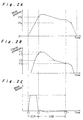
- Figs. 2A-2C are timing charts respectively showing the changes in position of the lower mold 10a, changes in the clamping pressure between the mold 10, and changes in the speed of the lower mold 10a during the injection-compression molding of resin.
- the lower mold is located at an injection start position P1 where no clamping force is generated between the mold 10.
- the control unit 8 effects position control of the movable lower mold 10a. That is, the lower mold 10a is moved at high speed to a clamping position P3, where it applies a clamping force lower than a predetermined target value F1 as shown in Figs. 2A and 2B.
- the clamping position P3 may be predetermined such that a force slightly lower than a target clamping force F1 is applied between the mold based on the correlation between the position of the lower mold and the pressure applied between the molds, and preset in the control program data.
- control unit 8 Upon detection of the lower mold 10a having reached the predetermined clamping position P3, the control unit 8 switches the control mode from position control to speed control which is based on the feedback of detected clamping force.
- Fig. 3 is a schematic control block diagram illustrating the speed control method in accordance with the invention.
- F denotes a target clamp pressure whereas F' denotes the detected pressure that is being applied.
- P represents a coefficient by which the difference between F and F' is multiplied.
- V represents a speed command value input to the servo motor. The speed command V is obtained by adding an integral of the difference between F and F' multiplied by a predetermined coefficient I to the proportionally multiplied value of the difference between F and F'.
- the speed of the servomotor for driving the lower mold 10a is controlled in accordance with the proportionally multiplied value of the difference between a target clamp pressure and the pressure that is actually being applied. While such control takes time, it enables slight pressure fluctuations to be responsively followed, whereby regulation of pressure to be applied is achieved with a high degree of precision.
- Compression of the resin is performed such that the pressure applied by the mold is gradually decreased as shown in Fig. 2B. That is, after a target clamp pressure F1 has been reached and maintained for a while, the lower mold is lowered so as to decrease the pressure.
- reduced pressure values F2 and F3 are reached stepwise during the period S3B precisely by the above-described speed feedback control.
- the control unit 8 Upon detecting the clamp pressure having reached a predetermined value F3, the control unit 8 switches the control mode from the clamping force control back to the position control.
- the lower mold 10a is swiftly moved to a predetermined position P4 and then back to an initial position.
- the switching of the control mode from the position control to the clamping force control may be effected automatically upon detection of the clamp pressure having reached the value F1' which is slightly lower than the target value F1.
- the clamping pressure control method of the invention As described above, according to the clamping pressure control method of the invention, after or during the injection of resin, the lower mold is swiftly moved to a predetermined position by the high speed position control, and thereafter, the control mode is switched to the clamping force control which enables fine regulation of pressure to be achieved in accordance with pressure fluctuations in the resin. After the compression of resin when such delicate control of clamping pressure is no more necessary, the control mode is switched back to the fast position control. In this way, the present invention achieves a considerable reduction in process time without compromising the quality of resultant molded articles by combining different control modes during the injection and compression of resin.
- the clamping pressure control method of this embodiment includes constant speed control of the movable lower mold 10a and speed feedback control thereof which is based on a detected clamping force.
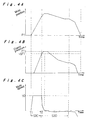
- Figs. 4A-4C are timing charts respectively showing the changes in position of the lower mold 10a, changes in the clamping pressure between the molds 10a and 10b, and changes in the speed of the lower mold 10a during the injection-compression molding of resin.
- the lower mold is located at the above-described injection start position P1.
- the control unit 8 effects constant speed control of the movable lower mold 10a. That is, the lower mold 10a is moved at a predetermined, constant, high speed V0, until the pressure applied between the molds is detected to have reached a level - ⁇ F1 which is lower than a target value F1 as shown in Figs. 4B and 4C.
- the speed V0 may be predetermined based on the correlation between the speed of the lower mold and the pressure applied between the molds, and preset in the control program data.
- control unit 8 Upon detection of the clamping pressure having reached the predetermined level - ⁇ F1, the control unit 8 switches the control mode from the constant speed control to speed feedback control which is based on the detected clamping force.
- the speed of the movable lower mold 10a is lowered so that the target clamping pressure F1 is precisely achieved.
- the target clamp pressure F1 must not be overshot to ensure uniform high quality of molded articles, and therefore the speed of the lower mold is instantly decreased upon the switching of the control modes at T2. Thereafter, during the period S3D, the above-described speed feedback control is effected.
- the constant speed control is effected such that, the speed of the lower mold is maintained constant by a speed command which is proportional to the difference between a target speed and the actual speed.
- a speed limit may be provided in the speed feedback control as shown in Fig. 5. That is, in producing speed command control V, a limit may be given so that the speed of the lower mold will never exceed the predetermined value V0.
- the lower mold 10a is first moved at high, constant speed, whereby a reduction in process time is achieved.
- the control mode is switched to speed feedback control and the speed of the lower mold instantly decreased as soon as the clamp pressure level has reached the level - ⁇ F1 which is lower than the target value F1.
- the target value F1 is precisely achieved without the risk of overshooting.
Landscapes
- Engineering & Computer Science (AREA)
- Manufacturing & Machinery (AREA)
- Mechanical Engineering (AREA)
- Injection Moulding Of Plastics Or The Like (AREA)
- Moulds For Moulding Plastics Or The Like (AREA)
Abstract
Description
Claims (5)
- A method for compression-molding a substrate, wherein molten resin is injected into a cavity between a stationary mold (10b) and a movable mold (10a) and molded into a desired shape by compressing the resin between the stationary mold and the movable mold by applying a clamping force therebetween, comprising:positioning the movable mold at a first position (P1) where no clamping force is generated between the stationary mold and the movable mold;injecting molten resin into the cavity between the stationary mold and the movable mold;moving the movable mold to a second position (P3) where a clamping force (F1') is generated between the stationary mold and the movable mold by positioning control of the movable mold;switching from positioning control of the movable mold to clamping force control upon detection of the movable mold having reached the second position (P3); andmoving the movable mold to a third position by the clamping force control, so that the clamping force generated between the stationary mold and the movable mold reaches and is maintained at a first target value (F1), wherein the speed of the movable mold is regulated in accordance with the difference between a target clamp pressure value and the clamping force being applied.
- A method for compression-molding a substrate as claimed in claim 1, further comprising the subsequent steps of:reducing the target clamp pressure; andswitching the clamping force control to positioning control upon detection of the clamping force having reached a second target value (F3) which is lower than the first target value (F1).
- A method for compression-molding a substrate as claimed in claim 2, including the further step of returning the movable mold to the initial position by positioning control.
- A method for compression-molding an optical disk substrate according to any one of the preceding claims, wherein, upon detection of the clamping force having reached a predetermined level (F1') lower than the first target value (F1) whereat the movable mold (10a) reaches the second position (P3), control of the movable mold is switched from positioning control to clamping force control.
- A method for compression-molding a substrate, wherein molten resin is injected into a cavity between a stationary mold (10b) and a movable mold (10a) and molded into a desired shape by compressing the resin between the stationary mold and the movable mold by applying a clamping force therebetween, comprising:positioning the movable mold at a first position (P1) where no clamping force is generated between the stationary mold and the movable mold;injecting molten resin into the cavity between the stationary mold and the movable mold;moving the movable mold towards the stationary mold at a substantially constant speed (V0) by constant speed control of the movable mold; switching the constant speed control of the movable mold to speed feedback control upon detection of a clamping force coming within a predetermined range (-▵F1) of a target value (F1); andmoving the movable mold toward the stationary mold by the speed feedback control, so that the clamping force generated between the stationary mold and the movable mold reaches the target value (F1), wherein the speed of the movable mold is regulated in accordance with the difference between a target clamp pressure value and the clamping force being applied.
Applications Claiming Priority (2)
| Application Number | Priority Date | Filing Date | Title |
|---|---|---|---|
| JP2000093306 | 2000-03-30 | ||
| JP2000093306 | 2000-03-30 |
Publications (2)
| Publication Number | Publication Date |
|---|---|
| EP1138459A2 true EP1138459A2 (en) | 2001-10-04 |
| EP1138459A3 EP1138459A3 (en) | 2002-04-03 |
Family
ID=18608503
Family Applications (1)
| Application Number | Title | Priority Date | Filing Date |
|---|---|---|---|
| EP01302846A Withdrawn EP1138459A3 (en) | 2000-03-30 | 2001-03-27 | Clamp pressure control of injection molder |
Country Status (5)
| Country | Link |
|---|---|
| US (1) | US6716374B2 (en) |
| EP (1) | EP1138459A3 (en) |
| KR (1) | KR100679802B1 (en) |
| CN (1) | CN1209233C (en) |
| TW (1) | TWI238770B (en) |
Families Citing this family (14)
| Publication number | Priority date | Publication date | Assignee | Title |
|---|---|---|---|---|
| NL1015140C2 (en) * | 2000-05-09 | 2001-11-13 | Otb Group Bv | Method and device for injection molding a plastic object. |
| KR100413266B1 (en) * | 2001-04-25 | 2003-12-31 | 주식회사 코스텍시스 | a injection molding system for optical fiber ferrule |
| JP2003191300A (en) * | 2001-12-26 | 2003-07-08 | Toshiba Mach Co Ltd | Method for injection compression molding of thin molded article and its apparatus |
| CN100493883C (en) * | 2002-12-30 | 2009-06-03 | 财团法人工业技术研究院 | Injection speed-pressure switching and pressure maintaining control device and method for electric injection molding machine |
| CN100491107C (en) * | 2003-10-06 | 2009-05-27 | 住友重机械工业株式会社 | Injection molding machine and injection molding method |
| JP4146382B2 (en) * | 2004-03-31 | 2008-09-10 | 日精樹脂工業株式会社 | Method for detecting mold closing position of mold clamping device |
| JP4015139B2 (en) * | 2004-06-28 | 2007-11-28 | ファナック株式会社 | Servo motor control device for forging machine |
| CN100584575C (en) * | 2004-11-02 | 2010-01-27 | 出光兴产株式会社 | Injection Compression Molding Method |
| JP6400314B2 (en) * | 2014-03-26 | 2018-10-03 | 住友重機械工業株式会社 | Injection molding machine |
| JP6284022B2 (en) * | 2014-04-22 | 2018-02-28 | 村田機械株式会社 | Clamping device |
| JP6137368B1 (en) * | 2016-03-24 | 2017-05-31 | 宇部興産機械株式会社 | Mold clamping control method of injection molding machine having toggle type mold clamping mechanism |
| CN109664455A (en) * | 2018-12-27 | 2019-04-23 | 佛山市顺德区震旭塑料机械有限公司 | A kind of injection molding machine with the secondary adjustment mold of inside groove |
| CN109795090A (en) * | 2019-02-18 | 2019-05-24 | 河源市昌红精机科技有限公司 | Mould control method is closed in a kind of printer bottom case and its injection molding |
| CN117042946A (en) * | 2021-04-28 | 2023-11-10 | 发那科株式会社 | Injection molding systems, injection molding machines and control devices |
Family Cites Families (8)
| Publication number | Priority date | Publication date | Assignee | Title |
|---|---|---|---|---|
| FR1539204A (en) * | 1967-08-03 | 1968-09-13 | Plastimonde | Improvements to the plastic molding process by adjusting the control of the movement of the mold and the injection piston |
| AT365119B (en) * | 1979-12-05 | 1981-12-10 | Engel Kg L | CONTROL FOR INJECTION MAKING, IN PARTICULAR LARGE-SCALE AND THIN-WALLED PLASTIC PARTS |
| GB2193681B (en) * | 1986-07-30 | 1989-12-13 | Toshiba Machine Co Ltd | A method of controlling mold clamping and compression in an injection molding machine |
| JPH01241420A (en) * | 1988-03-24 | 1989-09-26 | Komatsu Ltd | Molding method of injection compression molding machine and its molding device |
| JP2906349B2 (en) * | 1989-11-01 | 1999-06-21 | 住友重機械工業株式会社 | Manufacturing method of optical disk substrate |
| US5683630A (en) * | 1994-06-20 | 1997-11-04 | Matsushita Electric Industrial Co., Ltd. | Process for making optical disk substrates |
| US6048476A (en) * | 1998-03-16 | 2000-04-11 | Husky Injection Molding Systems Ltd. | Clamp pressure optimization system and method |
| US7097791B2 (en) * | 2000-02-09 | 2006-08-29 | Netstal Maschinen Ag | Method of controlling/regulating an embossing procedure and drive control device for injection molding machines |
-
2001
- 2001-03-27 EP EP01302846A patent/EP1138459A3/en not_active Withdrawn
- 2001-03-27 US US09/818,105 patent/US6716374B2/en not_active Expired - Fee Related
- 2001-03-30 CN CNB01112198XA patent/CN1209233C/en not_active Expired - Fee Related
- 2001-03-30 TW TW090107690A patent/TWI238770B/en not_active IP Right Cessation
- 2001-03-30 KR KR1020010016790A patent/KR100679802B1/en not_active Expired - Fee Related
Also Published As
| Publication number | Publication date |
|---|---|
| CN1209233C (en) | 2005-07-06 |
| EP1138459A3 (en) | 2002-04-03 |
| KR100679802B1 (en) | 2007-02-07 |
| US6716374B2 (en) | 2004-04-06 |
| TWI238770B (en) | 2005-09-01 |
| KR20010095142A (en) | 2001-11-03 |
| US20010038157A1 (en) | 2001-11-08 |
| CN1319490A (en) | 2001-10-31 |
Similar Documents
| Publication | Publication Date | Title |
|---|---|---|
| EP1138459A2 (en) | Clamp pressure control of injection molder | |
| JP3917459B2 (en) | Control device and control method for injection molding machine | |
| EP0397883B1 (en) | Injection compression molding machine and its molding method | |
| US7150619B2 (en) | Controller of injection molding machine | |
| JPWO2004089599A1 (en) | Control method of injection molding machine | |
| CN116018248B (en) | Injection molding machine and its control method | |
| US6042760A (en) | Injection molding method for an injection molding machine | |
| US6994537B2 (en) | Electrical injection velocity-pressure switching and pressure holding device | |
| JPS63178021A (en) | Method and apparatus for controlling injection molder | |
| JPH0622832B2 (en) | Injection compression molding method and apparatus | |
| JPH05237894A (en) | Method and apparatus for molding substrate for information recording medium | |
| JP2001277315A (en) | Method for injection compression molding and injection compression molding apparatus for executing the method | |
| JP2566492B2 (en) | Injection compression molding method | |
| JPH08281747A (en) | Mold clamping control method and mold clamping control device for injection molding machine | |
| JP2572802Y2 (en) | Mold clamping control device of injection molding machine | |
| JP3233608B2 (en) | Injection molding machine | |
| JP2917091B2 (en) | Control method of injection molding machine | |
| JP3858198B2 (en) | How to adjust warpage of disk substrate | |
| JP2926286B2 (en) | Control device for injection molding machine | |
| JPH0516197A (en) | Injection control method of injection molding machine | |
| JPS6313726A (en) | Method and equipment for injection compression molding | |
| JP2515506B2 (en) | Mold clamping control method for injection compression molding machine | |
| JP2828801B2 (en) | Injection molding machine | |
| JP2002361700A (en) | Mold clamping device for injection molding machine and method of controlling the device | |
| JPH10119099A (en) | Mold clamping force controller for toggle type motor operated injection molding machine |
Legal Events
| Date | Code | Title | Description |
|---|---|---|---|
| PUAI | Public reference made under article 153(3) epc to a published international application that has entered the european phase |
Free format text: ORIGINAL CODE: 0009012 |
|
| AK | Designated contracting states |
Kind code of ref document: A2 Designated state(s): AT BE CH CY DE DK ES FI FR GB GR IE IT LI LU MC NL PT SE TR |
|
| AX | Request for extension of the european patent |
Free format text: AL;LT;LV;MK;RO;SI |
|
| PUAL | Search report despatched |
Free format text: ORIGINAL CODE: 0009013 |
|
| AK | Designated contracting states |
Kind code of ref document: A3 Designated state(s): AT BE CH CY DE DK ES FI FR GB GR IE IT LI LU MC NL PT SE TR |
|
| AX | Request for extension of the european patent |
Free format text: AL;LT;LV;MK;RO;SI |
|
| AKX | Designation fees paid | ||
| REG | Reference to a national code |
Ref country code: DE Ref legal event code: 8566 |
|
| STAA | Information on the status of an ep patent application or granted ep patent |
Free format text: STATUS: THE APPLICATION IS DEEMED TO BE WITHDRAWN |
|
| 18D | Application deemed to be withdrawn |
Effective date: 20021005 |